EP0644547A2 - Module de mémoire intégrée multichip, structure et fabrication - Google Patents
Module de mémoire intégrée multichip, structure et fabrication Download PDFInfo
- Publication number
- EP0644547A2 EP0644547A2 EP94113741A EP94113741A EP0644547A2 EP 0644547 A2 EP0644547 A2 EP 0644547A2 EP 94113741 A EP94113741 A EP 94113741A EP 94113741 A EP94113741 A EP 94113741A EP 0644547 A2 EP0644547 A2 EP 0644547A2
- Authority
- EP
- European Patent Office
- Prior art keywords
- memory
- subunit
- chip
- chips
- stack
- Prior art date
- Legal status (The legal status is an assumption and is not a legal conclusion. Google has not performed a legal analysis and makes no representation as to the accuracy of the status listed.)
- Withdrawn
Links
- 238000004519 manufacturing process Methods 0.000 title claims abstract description 32
- 239000004065 semiconductor Substances 0.000 claims abstract description 82
- 238000001465 metallisation Methods 0.000 claims abstract description 60
- 238000000034 method Methods 0.000 claims abstract description 46
- 238000004891 communication Methods 0.000 claims abstract description 9
- 239000010410 layer Substances 0.000 claims description 89
- 238000005272 metallurgy Methods 0.000 claims description 59
- 239000000463 material Substances 0.000 claims description 37
- 238000012546 transfer Methods 0.000 claims description 30
- 230000011218 segmentation Effects 0.000 claims description 27
- 229920000052 poly(p-xylylene) Polymers 0.000 claims description 15
- 229910000679 solder Inorganic materials 0.000 claims description 15
- 239000010409 thin film Substances 0.000 claims description 13
- 238000012360 testing method Methods 0.000 claims description 7
- 239000012790 adhesive layer Substances 0.000 claims description 5
- 239000000853 adhesive Substances 0.000 claims description 3
- 230000001070 adhesive effect Effects 0.000 claims description 3
- 238000002161 passivation Methods 0.000 claims description 3
- 238000000151 deposition Methods 0.000 claims description 2
- 230000000977 initiatory effect Effects 0.000 claims description 2
- 239000002344 surface layer Substances 0.000 claims 5
- 230000004044 response Effects 0.000 claims 2
- 230000015572 biosynthetic process Effects 0.000 claims 1
- 230000008878 coupling Effects 0.000 claims 1
- 238000010168 coupling process Methods 0.000 claims 1
- 238000005859 coupling reaction Methods 0.000 claims 1
- 230000001105 regulatory effect Effects 0.000 claims 1
- 230000001131 transforming effect Effects 0.000 claims 1
- 238000013459 approach Methods 0.000 abstract description 8
- 238000000059 patterning Methods 0.000 abstract 1
- 239000000872 buffer Substances 0.000 description 20
- 238000005516 engineering process Methods 0.000 description 18
- 238000012545 processing Methods 0.000 description 14
- 229920001721 polyimide Polymers 0.000 description 13
- 239000004642 Polyimide Substances 0.000 description 12
- 239000004033 plastic Substances 0.000 description 12
- 229920003023 plastic Polymers 0.000 description 12
- 230000008569 process Effects 0.000 description 9
- 239000008393 encapsulating agent Substances 0.000 description 7
- 239000010408 film Substances 0.000 description 7
- 230000006870 function Effects 0.000 description 7
- 229920000642 polymer Polymers 0.000 description 7
- 229920001646 UPILEX Polymers 0.000 description 6
- 230000008901 benefit Effects 0.000 description 6
- 238000004806 packaging method and process Methods 0.000 description 6
- 235000012431 wafers Nutrition 0.000 description 6
- 238000005538 encapsulation Methods 0.000 description 5
- -1 poly(alpha methyl styrene) Polymers 0.000 description 4
- 239000000758 substrate Substances 0.000 description 4
- 230000006872 improvement Effects 0.000 description 3
- 238000001746 injection moulding Methods 0.000 description 3
- 238000009413 insulation Methods 0.000 description 3
- 239000012212 insulator Substances 0.000 description 3
- 230000008018 melting Effects 0.000 description 3
- 238000002844 melting Methods 0.000 description 3
- 230000009467 reduction Effects 0.000 description 3
- 238000003860 storage Methods 0.000 description 3
- 238000005979 thermal decomposition reaction Methods 0.000 description 3
- VRBFTYUMFJWSJY-UHFFFAOYSA-N 28804-46-8 Chemical compound ClC1CC(C=C2)=CC=C2C(Cl)CC2=CC=C1C=C2 VRBFTYUMFJWSJY-UHFFFAOYSA-N 0.000 description 2
- NXDMHKQJWIMEEE-UHFFFAOYSA-N 4-(4-aminophenoxy)aniline;furo[3,4-f][2]benzofuran-1,3,5,7-tetrone Chemical compound C1=CC(N)=CC=C1OC1=CC=C(N)C=C1.C1=C2C(=O)OC(=O)C2=CC2=C1C(=O)OC2=O NXDMHKQJWIMEEE-UHFFFAOYSA-N 0.000 description 2
- 229920002472 Starch Polymers 0.000 description 2
- 239000003990 capacitor Substances 0.000 description 2
- 230000007547 defect Effects 0.000 description 2
- 238000004100 electronic packaging Methods 0.000 description 2
- 230000009477 glass transition Effects 0.000 description 2
- 239000007788 liquid Substances 0.000 description 2
- 229910052751 metal Inorganic materials 0.000 description 2
- 239000002184 metal Substances 0.000 description 2
- 238000004377 microelectronic Methods 0.000 description 2
- 238000012986 modification Methods 0.000 description 2
- 230000004048 modification Effects 0.000 description 2
- 229920003223 poly(pyromellitimide-1,4-diphenyl ether) Polymers 0.000 description 2
- 239000008107 starch Substances 0.000 description 2
- 235000019698 starch Nutrition 0.000 description 2
- 229920001169 thermoplastic Polymers 0.000 description 2
- 239000004416 thermosoftening plastic Substances 0.000 description 2
- 230000007704 transition Effects 0.000 description 2
- 238000007158 vacuum pyrolysis Methods 0.000 description 2
- ZPZDIFSPRVHGIF-UHFFFAOYSA-N 3-aminopropylsilicon Chemical compound NCCC[Si] ZPZDIFSPRVHGIF-UHFFFAOYSA-N 0.000 description 1
- RYGMFSIKBFXOCR-UHFFFAOYSA-N Copper Chemical compound [Cu] RYGMFSIKBFXOCR-UHFFFAOYSA-N 0.000 description 1
- 239000004593 Epoxy Substances 0.000 description 1
- 101000859758 Homo sapiens Cartilage-associated protein Proteins 0.000 description 1
- 101000916686 Homo sapiens Cytohesin-interacting protein Proteins 0.000 description 1
- 101000726740 Homo sapiens Homeobox protein cut-like 1 Proteins 0.000 description 1
- 101000761460 Homo sapiens Protein CASP Proteins 0.000 description 1
- 101000761459 Mesocricetus auratus Calcium-dependent serine proteinase Proteins 0.000 description 1
- 102100024933 Protein CASP Human genes 0.000 description 1
- 229910018530 Si-Ag Inorganic materials 0.000 description 1
- 229910008383 Si—Ag Inorganic materials 0.000 description 1
- RTAQQCXQSZGOHL-UHFFFAOYSA-N Titanium Chemical compound [Ti] RTAQQCXQSZGOHL-UHFFFAOYSA-N 0.000 description 1
- 239000002318 adhesion promoter Substances 0.000 description 1
- 229910052782 aluminium Inorganic materials 0.000 description 1
- XAGFODPZIPBFFR-UHFFFAOYSA-N aluminium Chemical compound [Al] XAGFODPZIPBFFR-UHFFFAOYSA-N 0.000 description 1
- 230000003466 anti-cipated effect Effects 0.000 description 1
- 238000003491 array Methods 0.000 description 1
- 238000004380 ashing Methods 0.000 description 1
- 230000003139 buffering effect Effects 0.000 description 1
- 239000000969 carrier Substances 0.000 description 1
- 239000000919 ceramic Substances 0.000 description 1
- 239000011248 coating agent Substances 0.000 description 1
- 238000000576 coating method Methods 0.000 description 1
- 230000000295 complement effect Effects 0.000 description 1
- 230000006835 compression Effects 0.000 description 1
- 238000007906 compression Methods 0.000 description 1
- 239000000470 constituent Substances 0.000 description 1
- 229910052802 copper Inorganic materials 0.000 description 1
- 239000010949 copper Substances 0.000 description 1
- 238000012937 correction Methods 0.000 description 1
- 125000004122 cyclic group Chemical group 0.000 description 1
- 230000001934 delay Effects 0.000 description 1
- 230000001419 dependent effect Effects 0.000 description 1
- 230000008021 deposition Effects 0.000 description 1
- 238000013461 design Methods 0.000 description 1
- 238000010586 diagram Methods 0.000 description 1
- 239000003822 epoxy resin Substances 0.000 description 1
- 238000005530 etching Methods 0.000 description 1
- 238000002347 injection Methods 0.000 description 1
- 239000007924 injection Substances 0.000 description 1
- 238000010030 laminating Methods 0.000 description 1
- 238000003475 lamination Methods 0.000 description 1
- 230000003278 mimic effect Effects 0.000 description 1
- 239000012299 nitrogen atmosphere Substances 0.000 description 1
- 238000005457 optimization Methods 0.000 description 1
- 238000001020 plasma etching Methods 0.000 description 1
- 229920005575 poly(amic acid) Polymers 0.000 description 1
- 229920003229 poly(methyl methacrylate) Polymers 0.000 description 1
- 229920003251 poly(α-methylstyrene) Polymers 0.000 description 1
- 229920000647 polyepoxide Polymers 0.000 description 1
- 229920006254 polymer film Polymers 0.000 description 1
- 239000004926 polymethyl methacrylate Substances 0.000 description 1
- 239000002243 precursor Substances 0.000 description 1
- 238000002360 preparation method Methods 0.000 description 1
- 230000001681 protective effect Effects 0.000 description 1
- 230000008707 rearrangement Effects 0.000 description 1
- 239000011347 resin Substances 0.000 description 1
- 229920005989 resin Polymers 0.000 description 1
- 238000012216 screening Methods 0.000 description 1
- 238000000926 separation method Methods 0.000 description 1
- 238000010008 shearing Methods 0.000 description 1
- 229910052710 silicon Inorganic materials 0.000 description 1
- 239000010703 silicon Substances 0.000 description 1
- 238000007614 solvation Methods 0.000 description 1
- 239000002904 solvent Substances 0.000 description 1
- 238000006467 substitution reaction Methods 0.000 description 1
- 238000000427 thin-film deposition Methods 0.000 description 1
- 239000010936 titanium Substances 0.000 description 1
- 229910052719 titanium Inorganic materials 0.000 description 1
- 238000001039 wet etching Methods 0.000 description 1
- 239000008096 xylene Substances 0.000 description 1
Images


Classifications
-
- G—PHYSICS
- G11—INFORMATION STORAGE
- G11C—STATIC STORES
- G11C5/00—Details of stores covered by group G11C11/00
- G11C5/06—Arrangements for interconnecting storage elements electrically, e.g. by wiring
-
- G—PHYSICS
- G11—INFORMATION STORAGE
- G11C—STATIC STORES
- G11C11/00—Digital stores characterised by the use of particular electric or magnetic storage elements; Storage elements therefor
- G11C11/21—Digital stores characterised by the use of particular electric or magnetic storage elements; Storage elements therefor using electric elements
- G11C11/34—Digital stores characterised by the use of particular electric or magnetic storage elements; Storage elements therefor using electric elements using semiconductor devices
- G11C11/40—Digital stores characterised by the use of particular electric or magnetic storage elements; Storage elements therefor using electric elements using semiconductor devices using transistors
- G11C11/401—Digital stores characterised by the use of particular electric or magnetic storage elements; Storage elements therefor using electric elements using semiconductor devices using transistors forming cells needing refreshing or charge regeneration, i.e. dynamic cells
- G11C11/406—Management or control of the refreshing or charge-regeneration cycles
- G11C11/40611—External triggering or timing of internal or partially internal refresh operations, e.g. auto-refresh or CAS-before-RAS triggered refresh
-
- G—PHYSICS
- G11—INFORMATION STORAGE
- G11C—STATIC STORES
- G11C11/00—Digital stores characterised by the use of particular electric or magnetic storage elements; Storage elements therefor
- G11C11/21—Digital stores characterised by the use of particular electric or magnetic storage elements; Storage elements therefor using electric elements
- G11C11/34—Digital stores characterised by the use of particular electric or magnetic storage elements; Storage elements therefor using electric elements using semiconductor devices
- G11C11/40—Digital stores characterised by the use of particular electric or magnetic storage elements; Storage elements therefor using electric elements using semiconductor devices using transistors
- G11C11/401—Digital stores characterised by the use of particular electric or magnetic storage elements; Storage elements therefor using electric elements using semiconductor devices using transistors forming cells needing refreshing or charge regeneration, i.e. dynamic cells
- G11C11/406—Management or control of the refreshing or charge-regeneration cycles
- G11C11/40615—Internal triggering or timing of refresh, e.g. hidden refresh, self refresh, pseudo-SRAMs
-
- G—PHYSICS
- G11—INFORMATION STORAGE
- G11C—STATIC STORES
- G11C11/00—Digital stores characterised by the use of particular electric or magnetic storage elements; Storage elements therefor
- G11C11/21—Digital stores characterised by the use of particular electric or magnetic storage elements; Storage elements therefor using electric elements
- G11C11/34—Digital stores characterised by the use of particular electric or magnetic storage elements; Storage elements therefor using electric elements using semiconductor devices
- G11C11/40—Digital stores characterised by the use of particular electric or magnetic storage elements; Storage elements therefor using electric elements using semiconductor devices using transistors
- G11C11/401—Digital stores characterised by the use of particular electric or magnetic storage elements; Storage elements therefor using electric elements using semiconductor devices using transistors forming cells needing refreshing or charge regeneration, i.e. dynamic cells
- G11C11/406—Management or control of the refreshing or charge-regeneration cycles
- G11C11/40618—Refresh operations over multiple banks or interleaving
-
- G—PHYSICS
- G11—INFORMATION STORAGE
- G11C—STATIC STORES
- G11C5/00—Details of stores covered by group G11C11/00
- G11C5/02—Disposition of storage elements, e.g. in the form of a matrix array
- G11C5/04—Supports for storage elements, e.g. memory modules; Mounting or fixing of storage elements on such supports
-
- H—ELECTRICITY
- H01—ELECTRIC ELEMENTS
- H01L—SEMICONDUCTOR DEVICES NOT COVERED BY CLASS H10
- H01L24/00—Arrangements for connecting or disconnecting semiconductor or solid-state bodies; Methods or apparatus related thereto
- H01L24/01—Means for bonding being attached to, or being formed on, the surface to be connected, e.g. chip-to-package, die-attach, "first-level" interconnects; Manufacturing methods related thereto
- H01L24/42—Wire connectors; Manufacturing methods related thereto
- H01L24/47—Structure, shape, material or disposition of the wire connectors after the connecting process
- H01L24/49—Structure, shape, material or disposition of the wire connectors after the connecting process of a plurality of wire connectors
-
- H—ELECTRICITY
- H01—ELECTRIC ELEMENTS
- H01L—SEMICONDUCTOR DEVICES NOT COVERED BY CLASS H10
- H01L25/00—Assemblies consisting of a plurality of individual semiconductor or other solid state devices ; Multistep manufacturing processes thereof
- H01L25/03—Assemblies consisting of a plurality of individual semiconductor or other solid state devices ; Multistep manufacturing processes thereof all the devices being of a type provided for in the same subgroup of groups H01L27/00 - H01L33/00, or in a single subclass of H10K, H10N, e.g. assemblies of rectifier diodes
- H01L25/04—Assemblies consisting of a plurality of individual semiconductor or other solid state devices ; Multistep manufacturing processes thereof all the devices being of a type provided for in the same subgroup of groups H01L27/00 - H01L33/00, or in a single subclass of H10K, H10N, e.g. assemblies of rectifier diodes the devices not having separate containers
- H01L25/065—Assemblies consisting of a plurality of individual semiconductor or other solid state devices ; Multistep manufacturing processes thereof all the devices being of a type provided for in the same subgroup of groups H01L27/00 - H01L33/00, or in a single subclass of H10K, H10N, e.g. assemblies of rectifier diodes the devices not having separate containers the devices being of a type provided for in group H01L27/00
- H01L25/0657—Stacked arrangements of devices
-
- H—ELECTRICITY
- H01—ELECTRIC ELEMENTS
- H01L—SEMICONDUCTOR DEVICES NOT COVERED BY CLASS H10
- H01L2224/00—Indexing scheme for arrangements for connecting or disconnecting semiconductor or solid-state bodies and methods related thereto as covered by H01L24/00
- H01L2224/01—Means for bonding being attached to, or being formed on, the surface to be connected, e.g. chip-to-package, die-attach, "first-level" interconnects; Manufacturing methods related thereto
- H01L2224/02—Bonding areas; Manufacturing methods related thereto
- H01L2224/04—Structure, shape, material or disposition of the bonding areas prior to the connecting process
- H01L2224/05—Structure, shape, material or disposition of the bonding areas prior to the connecting process of an individual bonding area
- H01L2224/0554—External layer
- H01L2224/0555—Shape
- H01L2224/05552—Shape in top view
- H01L2224/05553—Shape in top view being rectangular
-
- H—ELECTRICITY
- H01—ELECTRIC ELEMENTS
- H01L—SEMICONDUCTOR DEVICES NOT COVERED BY CLASS H10
- H01L2224/00—Indexing scheme for arrangements for connecting or disconnecting semiconductor or solid-state bodies and methods related thereto as covered by H01L24/00
- H01L2224/01—Means for bonding being attached to, or being formed on, the surface to be connected, e.g. chip-to-package, die-attach, "first-level" interconnects; Manufacturing methods related thereto
- H01L2224/10—Bump connectors; Manufacturing methods related thereto
- H01L2224/15—Structure, shape, material or disposition of the bump connectors after the connecting process
- H01L2224/16—Structure, shape, material or disposition of the bump connectors after the connecting process of an individual bump connector
- H01L2224/161—Disposition
- H01L2224/16151—Disposition the bump connector connecting between a semiconductor or solid-state body and an item not being a semiconductor or solid-state body, e.g. chip-to-substrate, chip-to-passive
- H01L2224/16221—Disposition the bump connector connecting between a semiconductor or solid-state body and an item not being a semiconductor or solid-state body, e.g. chip-to-substrate, chip-to-passive the body and the item being stacked
- H01L2224/16225—Disposition the bump connector connecting between a semiconductor or solid-state body and an item not being a semiconductor or solid-state body, e.g. chip-to-substrate, chip-to-passive the body and the item being stacked the item being non-metallic, e.g. insulating substrate with or without metallisation
-
- H—ELECTRICITY
- H01—ELECTRIC ELEMENTS
- H01L—SEMICONDUCTOR DEVICES NOT COVERED BY CLASS H10
- H01L2224/00—Indexing scheme for arrangements for connecting or disconnecting semiconductor or solid-state bodies and methods related thereto as covered by H01L24/00
- H01L2224/01—Means for bonding being attached to, or being formed on, the surface to be connected, e.g. chip-to-package, die-attach, "first-level" interconnects; Manufacturing methods related thereto
- H01L2224/42—Wire connectors; Manufacturing methods related thereto
- H01L2224/47—Structure, shape, material or disposition of the wire connectors after the connecting process
- H01L2224/48—Structure, shape, material or disposition of the wire connectors after the connecting process of an individual wire connector
- H01L2224/4805—Shape
- H01L2224/4809—Loop shape
- H01L2224/48091—Arched
-
- H—ELECTRICITY
- H01—ELECTRIC ELEMENTS
- H01L—SEMICONDUCTOR DEVICES NOT COVERED BY CLASS H10
- H01L2224/00—Indexing scheme for arrangements for connecting or disconnecting semiconductor or solid-state bodies and methods related thereto as covered by H01L24/00
- H01L2224/01—Means for bonding being attached to, or being formed on, the surface to be connected, e.g. chip-to-package, die-attach, "first-level" interconnects; Manufacturing methods related thereto
- H01L2224/42—Wire connectors; Manufacturing methods related thereto
- H01L2224/47—Structure, shape, material or disposition of the wire connectors after the connecting process
- H01L2224/48—Structure, shape, material or disposition of the wire connectors after the connecting process of an individual wire connector
- H01L2224/481—Disposition
- H01L2224/48151—Connecting between a semiconductor or solid-state body and an item not being a semiconductor or solid-state body, e.g. chip-to-substrate, chip-to-passive
- H01L2224/48221—Connecting between a semiconductor or solid-state body and an item not being a semiconductor or solid-state body, e.g. chip-to-substrate, chip-to-passive the body and the item being stacked
- H01L2224/48225—Connecting between a semiconductor or solid-state body and an item not being a semiconductor or solid-state body, e.g. chip-to-substrate, chip-to-passive the body and the item being stacked the item being non-metallic, e.g. insulating substrate with or without metallisation
- H01L2224/48227—Connecting between a semiconductor or solid-state body and an item not being a semiconductor or solid-state body, e.g. chip-to-substrate, chip-to-passive the body and the item being stacked the item being non-metallic, e.g. insulating substrate with or without metallisation connecting the wire to a bond pad of the item
-
- H—ELECTRICITY
- H01—ELECTRIC ELEMENTS
- H01L—SEMICONDUCTOR DEVICES NOT COVERED BY CLASS H10
- H01L2224/00—Indexing scheme for arrangements for connecting or disconnecting semiconductor or solid-state bodies and methods related thereto as covered by H01L24/00
- H01L2224/01—Means for bonding being attached to, or being formed on, the surface to be connected, e.g. chip-to-package, die-attach, "first-level" interconnects; Manufacturing methods related thereto
- H01L2224/42—Wire connectors; Manufacturing methods related thereto
- H01L2224/47—Structure, shape, material or disposition of the wire connectors after the connecting process
- H01L2224/49—Structure, shape, material or disposition of the wire connectors after the connecting process of a plurality of wire connectors
- H01L2224/491—Disposition
- H01L2224/4911—Disposition the connectors being bonded to at least one common bonding area, e.g. daisy chain
-
- H—ELECTRICITY
- H01—ELECTRIC ELEMENTS
- H01L—SEMICONDUCTOR DEVICES NOT COVERED BY CLASS H10
- H01L2224/00—Indexing scheme for arrangements for connecting or disconnecting semiconductor or solid-state bodies and methods related thereto as covered by H01L24/00
- H01L2224/80—Methods for connecting semiconductor or other solid state bodies using means for bonding being attached to, or being formed on, the surface to be connected
- H01L2224/85—Methods for connecting semiconductor or other solid state bodies using means for bonding being attached to, or being formed on, the surface to be connected using a wire connector
- H01L2224/852—Applying energy for connecting
- H01L2224/85201—Compression bonding
- H01L2224/85205—Ultrasonic bonding
- H01L2224/85207—Thermosonic bonding
-
- H—ELECTRICITY
- H01—ELECTRIC ELEMENTS
- H01L—SEMICONDUCTOR DEVICES NOT COVERED BY CLASS H10
- H01L2225/00—Details relating to assemblies covered by the group H01L25/00 but not provided for in its subgroups
- H01L2225/03—All the devices being of a type provided for in the same subgroup of groups H01L27/00 - H01L33/648 and H10K99/00
- H01L2225/04—All the devices being of a type provided for in the same subgroup of groups H01L27/00 - H01L33/648 and H10K99/00 the devices not having separate containers
- H01L2225/065—All the devices being of a type provided for in the same subgroup of groups H01L27/00 - H01L33/648 and H10K99/00 the devices not having separate containers the devices being of a type provided for in group H01L27/00
- H01L2225/06503—Stacked arrangements of devices
- H01L2225/0651—Wire or wire-like electrical connections from device to substrate
-
- H—ELECTRICITY
- H01—ELECTRIC ELEMENTS
- H01L—SEMICONDUCTOR DEVICES NOT COVERED BY CLASS H10
- H01L2225/00—Details relating to assemblies covered by the group H01L25/00 but not provided for in its subgroups
- H01L2225/03—All the devices being of a type provided for in the same subgroup of groups H01L27/00 - H01L33/648 and H10K99/00
- H01L2225/04—All the devices being of a type provided for in the same subgroup of groups H01L27/00 - H01L33/648 and H10K99/00 the devices not having separate containers
- H01L2225/065—All the devices being of a type provided for in the same subgroup of groups H01L27/00 - H01L33/648 and H10K99/00 the devices not having separate containers the devices being of a type provided for in group H01L27/00
- H01L2225/06503—Stacked arrangements of devices
- H01L2225/06517—Bump or bump-like direct electrical connections from device to substrate
-
- H—ELECTRICITY
- H01—ELECTRIC ELEMENTS
- H01L—SEMICONDUCTOR DEVICES NOT COVERED BY CLASS H10
- H01L2225/00—Details relating to assemblies covered by the group H01L25/00 but not provided for in its subgroups
- H01L2225/03—All the devices being of a type provided for in the same subgroup of groups H01L27/00 - H01L33/648 and H10K99/00
- H01L2225/04—All the devices being of a type provided for in the same subgroup of groups H01L27/00 - H01L33/648 and H10K99/00 the devices not having separate containers
- H01L2225/065—All the devices being of a type provided for in the same subgroup of groups H01L27/00 - H01L33/648 and H10K99/00 the devices not having separate containers the devices being of a type provided for in group H01L27/00
- H01L2225/06503—Stacked arrangements of devices
- H01L2225/06551—Conductive connections on the side of the device
-
- H—ELECTRICITY
- H01—ELECTRIC ELEMENTS
- H01L—SEMICONDUCTOR DEVICES NOT COVERED BY CLASS H10
- H01L2225/00—Details relating to assemblies covered by the group H01L25/00 but not provided for in its subgroups
- H01L2225/03—All the devices being of a type provided for in the same subgroup of groups H01L27/00 - H01L33/648 and H10K99/00
- H01L2225/04—All the devices being of a type provided for in the same subgroup of groups H01L27/00 - H01L33/648 and H10K99/00 the devices not having separate containers
- H01L2225/065—All the devices being of a type provided for in the same subgroup of groups H01L27/00 - H01L33/648 and H10K99/00 the devices not having separate containers the devices being of a type provided for in group H01L27/00
- H01L2225/06503—Stacked arrangements of devices
- H01L2225/06572—Auxiliary carrier between devices, the carrier having an electrical connection structure
-
- H—ELECTRICITY
- H01—ELECTRIC ELEMENTS
- H01L—SEMICONDUCTOR DEVICES NOT COVERED BY CLASS H10
- H01L2225/00—Details relating to assemblies covered by the group H01L25/00 but not provided for in its subgroups
- H01L2225/03—All the devices being of a type provided for in the same subgroup of groups H01L27/00 - H01L33/648 and H10K99/00
- H01L2225/04—All the devices being of a type provided for in the same subgroup of groups H01L27/00 - H01L33/648 and H10K99/00 the devices not having separate containers
- H01L2225/065—All the devices being of a type provided for in the same subgroup of groups H01L27/00 - H01L33/648 and H10K99/00 the devices not having separate containers the devices being of a type provided for in group H01L27/00
- H01L2225/06503—Stacked arrangements of devices
- H01L2225/06582—Housing for the assembly, e.g. chip scale package [CSP]
-
- H—ELECTRICITY
- H01—ELECTRIC ELEMENTS
- H01L—SEMICONDUCTOR DEVICES NOT COVERED BY CLASS H10
- H01L24/00—Arrangements for connecting or disconnecting semiconductor or solid-state bodies; Methods or apparatus related thereto
- H01L24/01—Means for bonding being attached to, or being formed on, the surface to be connected, e.g. chip-to-package, die-attach, "first-level" interconnects; Manufacturing methods related thereto
- H01L24/42—Wire connectors; Manufacturing methods related thereto
- H01L24/47—Structure, shape, material or disposition of the wire connectors after the connecting process
- H01L24/48—Structure, shape, material or disposition of the wire connectors after the connecting process of an individual wire connector
-
- H—ELECTRICITY
- H01—ELECTRIC ELEMENTS
- H01L—SEMICONDUCTOR DEVICES NOT COVERED BY CLASS H10
- H01L2924/00—Indexing scheme for arrangements or methods for connecting or disconnecting semiconductor or solid-state bodies as covered by H01L24/00
- H01L2924/0001—Technical content checked by a classifier
- H01L2924/00014—Technical content checked by a classifier the subject-matter covered by the group, the symbol of which is combined with the symbol of this group, being disclosed without further technical details
-
- H—ELECTRICITY
- H01—ELECTRIC ELEMENTS
- H01L—SEMICONDUCTOR DEVICES NOT COVERED BY CLASS H10
- H01L2924/00—Indexing scheme for arrangements or methods for connecting or disconnecting semiconductor or solid-state bodies as covered by H01L24/00
- H01L2924/01—Chemical elements
- H01L2924/01005—Boron [B]
-
- H—ELECTRICITY
- H01—ELECTRIC ELEMENTS
- H01L—SEMICONDUCTOR DEVICES NOT COVERED BY CLASS H10
- H01L2924/00—Indexing scheme for arrangements or methods for connecting or disconnecting semiconductor or solid-state bodies as covered by H01L24/00
- H01L2924/01—Chemical elements
- H01L2924/01006—Carbon [C]
-
- H—ELECTRICITY
- H01—ELECTRIC ELEMENTS
- H01L—SEMICONDUCTOR DEVICES NOT COVERED BY CLASS H10
- H01L2924/00—Indexing scheme for arrangements or methods for connecting or disconnecting semiconductor or solid-state bodies as covered by H01L24/00
- H01L2924/01—Chemical elements
- H01L2924/01013—Aluminum [Al]
-
- H—ELECTRICITY
- H01—ELECTRIC ELEMENTS
- H01L—SEMICONDUCTOR DEVICES NOT COVERED BY CLASS H10
- H01L2924/00—Indexing scheme for arrangements or methods for connecting or disconnecting semiconductor or solid-state bodies as covered by H01L24/00
- H01L2924/01—Chemical elements
- H01L2924/01029—Copper [Cu]
-
- H—ELECTRICITY
- H01—ELECTRIC ELEMENTS
- H01L—SEMICONDUCTOR DEVICES NOT COVERED BY CLASS H10
- H01L2924/00—Indexing scheme for arrangements or methods for connecting or disconnecting semiconductor or solid-state bodies as covered by H01L24/00
- H01L2924/01—Chemical elements
- H01L2924/01047—Silver [Ag]
-
- H—ELECTRICITY
- H01—ELECTRIC ELEMENTS
- H01L—SEMICONDUCTOR DEVICES NOT COVERED BY CLASS H10
- H01L2924/00—Indexing scheme for arrangements or methods for connecting or disconnecting semiconductor or solid-state bodies as covered by H01L24/00
- H01L2924/01—Chemical elements
- H01L2924/01058—Cerium [Ce]
-
- H—ELECTRICITY
- H01—ELECTRIC ELEMENTS
- H01L—SEMICONDUCTOR DEVICES NOT COVERED BY CLASS H10
- H01L2924/00—Indexing scheme for arrangements or methods for connecting or disconnecting semiconductor or solid-state bodies as covered by H01L24/00
- H01L2924/01—Chemical elements
- H01L2924/01075—Rhenium [Re]
-
- H—ELECTRICITY
- H01—ELECTRIC ELEMENTS
- H01L—SEMICONDUCTOR DEVICES NOT COVERED BY CLASS H10
- H01L2924/00—Indexing scheme for arrangements or methods for connecting or disconnecting semiconductor or solid-state bodies as covered by H01L24/00
- H01L2924/013—Alloys
- H01L2924/014—Solder alloys
-
- H—ELECTRICITY
- H01—ELECTRIC ELEMENTS
- H01L—SEMICONDUCTOR DEVICES NOT COVERED BY CLASS H10
- H01L2924/00—Indexing scheme for arrangements or methods for connecting or disconnecting semiconductor or solid-state bodies as covered by H01L24/00
- H01L2924/10—Details of semiconductor or other solid state devices to be connected
- H01L2924/11—Device type
- H01L2924/12—Passive devices, e.g. 2 terminal devices
- H01L2924/1204—Optical Diode
- H01L2924/12042—LASER
-
- H—ELECTRICITY
- H01—ELECTRIC ELEMENTS
- H01L—SEMICONDUCTOR DEVICES NOT COVERED BY CLASS H10
- H01L2924/00—Indexing scheme for arrangements or methods for connecting or disconnecting semiconductor or solid-state bodies as covered by H01L24/00
- H01L2924/10—Details of semiconductor or other solid state devices to be connected
- H01L2924/11—Device type
- H01L2924/14—Integrated circuits
-
- H—ELECTRICITY
- H01—ELECTRIC ELEMENTS
- H01L—SEMICONDUCTOR DEVICES NOT COVERED BY CLASS H10
- H01L2924/00—Indexing scheme for arrangements or methods for connecting or disconnecting semiconductor or solid-state bodies as covered by H01L24/00
- H01L2924/15—Details of package parts other than the semiconductor or other solid state devices to be connected
- H01L2924/151—Die mounting substrate
- H01L2924/1515—Shape
- H01L2924/15153—Shape the die mounting substrate comprising a recess for hosting the device
-
- H—ELECTRICITY
- H01—ELECTRIC ELEMENTS
- H01L—SEMICONDUCTOR DEVICES NOT COVERED BY CLASS H10
- H01L2924/00—Indexing scheme for arrangements or methods for connecting or disconnecting semiconductor or solid-state bodies as covered by H01L24/00
- H01L2924/15—Details of package parts other than the semiconductor or other solid state devices to be connected
- H01L2924/151—Die mounting substrate
- H01L2924/1517—Multilayer substrate
-
- H—ELECTRICITY
- H01—ELECTRIC ELEMENTS
- H01L—SEMICONDUCTOR DEVICES NOT COVERED BY CLASS H10
- H01L2924/00—Indexing scheme for arrangements or methods for connecting or disconnecting semiconductor or solid-state bodies as covered by H01L24/00
- H01L2924/15—Details of package parts other than the semiconductor or other solid state devices to be connected
- H01L2924/181—Encapsulation
-
- H—ELECTRICITY
- H01—ELECTRIC ELEMENTS
- H01L—SEMICONDUCTOR DEVICES NOT COVERED BY CLASS H10
- H01L2924/00—Indexing scheme for arrangements or methods for connecting or disconnecting semiconductor or solid-state bodies as covered by H01L24/00
- H01L2924/19—Details of hybrid assemblies other than the semiconductor or other solid state devices to be connected
- H01L2924/1901—Structure
- H01L2924/1904—Component type
- H01L2924/19041—Component type being a capacitor
-
- H—ELECTRICITY
- H01—ELECTRIC ELEMENTS
- H01L—SEMICONDUCTOR DEVICES NOT COVERED BY CLASS H10
- H01L2924/00—Indexing scheme for arrangements or methods for connecting or disconnecting semiconductor or solid-state bodies as covered by H01L24/00
- H01L2924/19—Details of hybrid assemblies other than the semiconductor or other solid state devices to be connected
- H01L2924/191—Disposition
- H01L2924/19101—Disposition of discrete passive components
- H01L2924/19107—Disposition of discrete passive components off-chip wires
Definitions
- the present invention relates in one aspect to high density electronic packaging which permits optimization of device performance within a given volume.
- the invention relates to an integrated multichip memory module structure and method of fabrication wherein stacked semiconductor memory chips are integrated by controlling logic such that a more powerful memory architecture having the functions of a single, higher level memory chip is presented to external circuitry.
- integrated circuit devices such as memory devices
- wafers of semiconductor material which include a plurality of integrated circuits.
- the circuits are separated from each other by dicing the wafer into small chips. Thereafter, the chips are bonded to carriers of various types, electrically interconnected by wires to leads and packaged.
- This metallization pattern typically includes both individual contacts and bused contacts.
- the stack is positioned on an upper surface of a substrate such that electrical contact is made between the stack metallization pattern and a substrate surface metallization pattern.
- Next generation DRAM memory chips have traditionally increased by 4 ⁇ the number of bits compared with current generation technology.
- the current generation of memory chips comprises 16 megabit (Mb) chips
- the next generation will comprise 64Mb memory chips.
- This 4 ⁇ advancement from one generation of memory chips to the next generation is traditionally accomplished only with corresponding advancement in semiconductor tool and process technologies, for example, sufficient to attain a 2 ⁇ reduction in surface geometries. Due to this interrelationship, a significant interval of time can pass between generations of memory chips. Therefore, a genuine improvement in memory system design and fabrication would be attained if current generation memory chips could be packaged to have the same functions and physical dimensions of an anticipated, next generation memory chip.
- the integrated multichip memory module structure and fabrication techniques presented herein provide such an improvement.
- the present invention comprises in one aspect an integrated multichip memory module which appears to external, i.e., next level of packaging, circuitry to have a single memory chip architecture.
- the memory module includes a memory subunit having N memory chips wherein N ⁇ 2.
- Each memory chip of the memory subunit has M memory devices wherein M ⁇ 2, along with two substantially parallel planar main surfaces and an edge surface.
- At least one planar main surface of each memory chip is coupled to a planar main surface of an adjacent memory chip of the memory subunit such that the subunit has a stack structure.
- Logic means is associated with the memory subunit and electrically connected to each of the N memory chips for coordinating external communication with the N memory chips of the memory subunit such that an integrated memory structure exists that emulates a single memory chip architecture with N ⁇ M memory devices.
- an integrated multichip memory module wherein N memory chips, each having M memory devices, are integrated in an architecture which functionally emulates a single memory chip architecture with N ⁇ M memory devices.
- Each memory chip includes two substantially parallel planar main surfaces and an edge surface.
- the N memory chips are stacked together to form a subunit having at least one side surface and an end surface.
- the at least one side surface of the subunit is defined by the edge surfaces of the N memory chips.
- the end surface of the subunit is parallel to the planar main surfaces of the N memory chips forming the subunit.
- At least some of the N memory chips include transfer metallurgy extending from the chip's input/output (I/O) pads to the at least one side surface of the subunit.
- a first metallization pattern is disposed on the subunit's at least one side surface to electrically connect with the transfer metallurgy extending thereto.
- An electrical interface layer disposed adjacent to the end surface of the subunit, also has two substantially parallel planar main surfaces and an edge surface. One of the substantially parallel planar main surfaces of the electrical interface layer is coupled to the end surface of the subunit. The edge surface of the electrical interface layer aligns with the at least one side surface of the subunit.
- the electrical interface layer includes a second metallization pattern disposed therethrough which electrically connects with the first metallization pattern on the at least one side surface of the subunit.
- a logic chip is coupled to the electrical interface layer and electrically connected to the second metallization pattern such that the logic chip is electrically connected to the memory chips through the first and second metallization patterns.
- the logic chip includes logic means for coordinating external communication with the N memory chips of the subunit such that an integrated memory structure exists which functionally emulates a single memory chip architecture with N ⁇ M memory devices.
- a multichip integrated circuit package having a plurality of semiconductor chips of similar dimensions coupled together in a stack having an end surface and at least one edge surface.
- a lead frame is secured to the stack at its end surface.
- the lead frame includes an inner opening extending therethrough such that a portion of the stack's end surface remains exposed.
- a semiconductor chip of smaller dimensions than the similar dimensions of the plurality of semiconductor chips forming the stack is also provided. This semiconductor chip is sized so as to reside within the inner opening of the lead frame and be secured to the portion of the stack's end surface remaining exposed.
- metallurgy means are provided for electrically interconnecting the plurality of semiconductor chips forming the stack, the semiconductor chip of smaller dimensions and the lead frame such that a dense multichip integrated circuit package is defined from semiconductor chips having different dimensions.
- Fabrication processes corresponding to the various embodiments of the multichip integrated circuit module/package are also described.
- a particularly novel process is presented for facilitating side surface metallization of a plurality of semiconductor chip subassemblies using a sacrificial material disposed between the subassemblies.
- the resultant structure can emulate a next generation memory chip using readily available current generation memory chips.
- a packaged module can have physical dimensions smaller than industry standards for a next generation memory chip package.
- Wiring interfaces between existing and next generation buses can be contained in a preformed electrical interface layer which can be manufactured and tested separately.
- Logic chip transfer metallurgy to a side of the structure is eliminated, thereby also eliminating any special processing and testing for the logic chip. Testing and burn-in of the logic chip, memory chip subassembly and preformed electrical interface layer can be separately conducted, thus identifying a potential defect at a lower level assembly.
- the controlling logic chip can reside entirely within an inner opening in the lead frame.
- any number of semiconductor chips can be employed within a module's stack. The number employed depends upon the memory chip architecture selected and the memory module architecture desired.
- the logic control function can be allocated over one or more chips fitting within the lead frame opening on the preformed electrical interface layer. Decoupling capacitors and resistors can also be placed within the lead frame opening and attached to the electrical interface layer.
- An integrated multichip memory module in accordance with the invention can be implemented using any one of a variety of available memory chip architectures.
- the following discussion assumes that four 16Mb DRAMs are to be assembled in a memory stack.
- This multichip memory module emulates exactly a next generation memory chip, i.e., a 64Mb DRAM.
- This integrated, function is accomplished by associating a control logic chip with the stack of four memory chips.
- the resultant module of four 16Mb DRAMs plus logic chip can be sized to fit into an industry standard 64Mb package, or if desired, a smaller package. Compared with single memory chips, there are significant processing, manufacturability and cost advantages to this integrated multichip memory module structure in accordance with this invention.
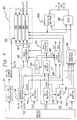
- Fig. 1 depicts one embodiment of the integrated multichip memory module, generally denoted 10, pursuant to the invention.
- M memory chips
- Each memory chip 14 has two substantially parallel planar main surfaces and an edge surface with at least one planar main surface of each memory chip being coupled to a planar main surface of an adjacent memory chip in the stack 12.
- Multiple layers 16 are disposed between adjacent memory chips 14.
- Each layer 16 contains appropriate transfer metallurgy 15 ( Fig. 2 ) and insulation layers 17A to provide electrical connection to the storage devices of the respective memory chip.
- An adhesive layer 17 ( Fig. 5 ) such as a Thermid® polymer (TM of National Starch and Chemical Co.) secures adjacent memory chips 14 together.
- a preformed electrical interface layer 18 Disposed along at least one end surface of stack 12 is a preformed electrical interface layer 18 which has a metallization pattern 28 therethrough.
- layer 18 comprises a Upilex (or alternative insulator) flex layer wherein plated throughholes or vias interconnect some thin-film wiring on a top surface of layer 18 and thin-film wiring on a bottom surface of the layer (see, e.g., Fig. 2 ).
- a Upilex (or alternative insulator) flex layer wherein plated throughholes or vias interconnect some thin-film wiring on a top surface of layer 18 and thin-film wiring on a bottom surface of the layer (see, e.g., Fig. 2 ).
- FIG. 2 shows a top surface thin-film wiring 25B which provides for the interconnection of the logic chip 22 and lead frame 32.
- metallization pattern 28 only one thin-film wire is shown in phantom in Fig. 1 .
- the metallization pattern within electrical interface layer 18 routes, for example, 16Mb wiring from a control logic chip 22 to another metallization pattern 20 disposed on an insulator 21 on at least one side surface of stack 12.
- metallization pattern 20 Only one type of metallization pattern 20 is depicted in Fig. 1 for clarity. T connects are employed at the interface between metallization pattern 28 and metallization pattern 20. If desired, multiple side surfaces of stack 12 could accommodate buses or other wiring connections to the semiconductor memory chips (M). Standard transfer metallurgy 15 is brought out and electrically connected to metallization pattern 20 on the at least one side surface of stack 12. Again, interconnection of transfer metallurgy 15 and metallization pattern 20 is achieved using T-connects.
- control logic chip 22 has dimensions smaller than the common dimensions of memory chips 14 forming stack 12. This size difference allows control logic chip 22 to be placed within a center opening 25 in a lead frame 32 (comprised of the lead 34 and the insulation/adhesive layer 30) disposed above preformed electrical interface layer 18.
- Lead frame 32 which surrounds logic chip 22, contains multiple leads, with only one lead 34 being shown.
- External circuitry connects to module 10 via, for example, a conventional lead 34.
- Standard wirebond technology is used to interconnect the logic chip 22 and memory chip stack 12 to the lead 34.
- a wire 31 is used to interconnect the lead and a contact pad 25B on the surface of interface layer 18.
- a second wire 31A interconnects contact pad 25B and I/O pad 24 on control logic chip 22. (An alternative interconnection technique would have wire 31 interconnect lead 34 and logic chip I/O 24.)
- wire 26 interconnects I/O pad 24 on control logic chip 22 and contact pad 25A on the surface of interface layer 18.
- contact pad 25A on interface layer 18 comprises part of metallization pattern 28.
- Metallization pattern 28 is connected to metallization pattern 20 on at least one side surface of stack 12.
- wires 26, 31, and 31A connect to arrays of leads 34 and contact pads 25A and 25B. Only three interconnecting wires are depicted in Fig. 1 and Fig. 2 . In actual implementation, there is a plurality of interconnections between logic chips 22, pads 25A and 25B on interface layer 18, and lead frame 32 including wires 26, 31, and 31A.
- the 64Mb and 16Mb wiring connections are also shown in Fig. 2 .
- wires 31 & 31A and lead 34 comprise 64Mb wiring
- wires 26, 28 and 20 comprise 16Mb wiring.
- thin-film 16Mb wiring 15 is shown above the top planar surface of each memory chip 14. This wiring 15 represents the transfer metallurgy from each memory chip 14 to chip I/O 14A to metallization pattern 20 on the side surface of stack 12. A plurality of thin-film wirings would typically connect each memory chip to the side surface metallization pattern.
- Fig. 2 also shows a completed package wherein an encapsulant 40 surrounds the multichip memory module. Encapsulant 40 can comprise any conventional encapsulating material.
- external wiring (64Mb) to integrated multichip memory module 10 is separate from intra-module wiring, i.e., 16Mb wiring.
- logic chip 22 which can reside within center opening 25 in lead frame 32. Very little area is required to implement the logic circuits described below. Therefore, extra area within logic chip 22 can be used for customer-specific applications. These applications include SRAM, psuedostatic RAM, error correction code, memory handshaking, and array built-in self-testing. Inclusion of such applications on logic chip 22 could dramatically improve performance of the chip for customer-specific uses.
- the basic method to "fit" an integrated multichip memory module, comprised of current generation chips, e.g., 16Mb, into a plastic package that is smaller in volume than the initial next generation, e.g., 64Mb, industry standard (JEDEC) package is to trade plastic encapsulation material for silicon, i.e., multiple semiconductor chips.
- initial next generation chip packaging grows in length and width proportional to next generation chip size.
- Plastic package height has remained constant through several memory chip technology generations.
- chip size shrinks as the technology matures With a commensurate reduction in plastic packaging size. In general, this shrinking proceeds to the point where the next generation chip approximately equals the size of the previous, fully mature, generation. Therefore a multichip memory module that emulates a next generation technology in accordance with the present invention can be readily fabricated to have smaller length and width than the initial single next generation memory chip.
- the height of the multichip memory module plastic package can exactly meet the next generation JEDEC height standards by reducing the thickness of the plastic encapsulant and/or reducing the thickness of the memory chips comprising the multichip module. Thereby resulting in a smaller plastic package compared with single chip next generation packaging.
- Fig. 3 depicts another embodiment of an integrated multichip memory module 50 in accordance with the invention.
- stack 12 with multiple semiconductor chips 14 is substantially the same as to that described above in connection with Figs. 1 & 2 .
- preformed electrical interface layer 18 is at least disposed above the upper surface of the top-most memory chip in the stack.
- a point of difference with module 10 of Fig. 1 comprises a control logic chip 52 having an array of contact pads on its bottom surface, along with the electrical connections made thereto.
- solder bumps 54 are employed to connect electrically and mechanically connect chip 52 to memory chips 14 via the metallurgy of layer 18 and the stack's at least one side surface metallurgy.
- Chip 52 connects to the lead 58 through, for example, a 64Mb thin-film bus 57 on the upper surface of layer 18, using wire 56.
- the lead frame 60 provides the means to interconnect to the next packaging level.
- lead frame 60 has an inner opening that accommodates the controlling logic chip, which is smaller than the semiconductor chips 14 forming stack 12.
- Standard wirebond technology is used to electrically connect the lead frame 60 and the metallurgy pad 57 on interface layer 18.
- Metallization pattern 20, disposed on an insulator 21, is used to interconnect electrically the memory chips in stack 12 and the logic chip 52.
- T-connects are used to interconnect transfer metallurgy 15 with metallization 20 and interface layer 18 metallization 28 with metallization 20.
- the resultant structure is injection molded with a protective encapsulant 40 such as that depicted in Fig. 2 .
- a protective encapsulant 40 such as that depicted in Fig. 2 .
- One feature to again note is the dense stacking achieved in part through the provision of a reduced size logic chip that can reside within a center opening in the lead frame.
- This particular stacking configuration could obviously be generalized for other integrated circuit chip stacks.
- one or more chips could be attached to the memory stack in a manner similar to that described herein. Further, the number of semiconductor chips in the stack could be modified as needed for a particular application.
- FIG. 4 An overview of one embodiment of a control logic circuit in accordance with the present invention is depicted in Fig. 4 .
- This logic circuit denoted 70, receives address and control inputs 72 from a memory controller (not shown) or other external processing unit.
- Logic circuit 70 is designed to industry standards for a next generation single memory chip input timings. For example, if the semiconductor memory chips in the stack comprise 64Mb memory chips, then logic 70 would have the same I/O characteristics as a 256Mb single memory chip.
- a voltage regulator 71 can be provided to allow powering of logic circuit 70 by either a five volt or three volt source. This suggests another feature of the invention. If desired, the logic chip could be powered at a different voltage level than the supply provided to the chip stack 84.
- each chip provides 1 ⁇ 4 of a 64Mb memory array.
- a desired product is a 13/11 addressable, 16Mb ⁇ 4 array.
- 13 bits enter address buffers 74.
- a 12 bit signal is passed from address buffer 74 to stack 84.
- RAS time one bit of the incoming 13 bits is split off and fed to a RAS decoder 86.
- CAS time one bit of the received 11 bit signal is split off and fed to a CAS decoder 88.
- RAS and CAS timing pulses are received by a RAS enable buffer 76 and a CAS enable buffer 78, respectively, from module input 72.
- Output from buffer 76 is a RASP signal comprising a RAS pulse, positive active high. This pulse is output from RE buffer 76 whenever the buffer detects its input going low. The signal is also fed to address buffer 74 to enable/disable the address buffers. Similarly, output CASP from CE buffer 78 is fed to a write enable buffer 80 to provide enable/disable control. Output from RAS enable buffer 76 and one address from address buffer 74 are fed to RAS decoder 86, which outputs two signals RE1 and RE2. Together, these signals select two of the four memory chips in stack 84. Only signal RE1 or signal RE2 has an applied voltage (i.e., is in active state) based upon the inputs received by RAS decoder 86.
- the approach to selecting a particular semiconductor chip is dependent upon the architecture employed. For example, if an 11/11 4MB ⁇ 4 semiconductor chip is used then two bits would be required for input to the RAS decoder. Upon receipt of an appropriate RASP pulse one of the four semiconductor chips would be directly selected by the RAS decoder. In such a case, the CAS decoder output would be connected to all four chips in stack 84. However, with 12/10 16Mb chips, CAS decoder 88 will need to output one of two signals CE1 and CE2. Signals CE1 and CE2 are fed back to the memory chips of stack 84 in an interleaved fashion relative to signals RE1 and RE2.
- a comparator is employed as a CBR detect circuit 90 to identify the JEDEC standard timing of when a CAS pulse occurs before a RAS pulse. Such an ordering occurs when the memory controller (or system controller) directs that a memory refresh should occur.
- a RAC counter 94 counts each CBR output pulse and sequentially directs which semiconductor chip in stack 84 is to be refreshed. Thus, sequential refreshing of semiconductor chips is ensured irrespective of which chip signal RAS 13 and signal CAS 11 identify.
- a self-time refresh (STR) circuit 92 also receives output from CAS before RAS detect 90.
- This circuit controls initiation of a "sleep mode" whereby if the CAS signal appears before the RAS signal and, for example, is held active for at least 100 microseconds, sleep mode for all four 16Mb ⁇ 4 semiconductor chips are invoked via RAS decoder 86 and CAS decoder 88.
- an output enable buffer 82 receives pulse signals from said external source. Outputs from buffers 76, 78, 80 and 82 are fed to a conventional tristate control 96 which feeds off chip driver (OCD) 98 and a data in buffer 100.
- OCD off chip driver
- Tristate control 96 deselects the data in buffer 100 when an output is being driven to bus DQ (0-3) or, alternatively, turns off OCD 98 when data is being received at buffer 100.
- logic circuit 70 is in addition to the standard logic and timing circuits inherent on the 16Mb semiconductor memory chips in stack 84.
- Logic circuit 70 comprises a control logic circuit designed to emulate a single semiconductor memory chip, in this case a 64Mb chip.
- logic circuit 70 is designed with two constraints. The first constraint comprises the known architecture of the selected memory chips in the stack, and the second constraint comprises the JEDEC standard operation of a 64Mb chip. Further, note that logic circuit 70 can be employed in different memory I/O configurations.
- control circuit 70 For example, if for a given application a by eight bit output is desired, then two chips, each simultaneously activated by control circuit 70 (each by four), can be coupled together to mimic the desired by eight architecture.
- logic circuit 70 could implement various additional logic functions as desired. Such functions might include ECC, boundary scan, toggle mode, additional memory for sparing, storage devices, timing delays, memory control, data handling, write per bit, toggle mode, I/O buffering, address re-configuring or active terminating.
- Fabrication of an integrated multichip memory module in accordance with this invention is analogous in many respects to the fabrication approach presented in co-pending U.S. Patent Application entitled “Polyimide-Insulated Cube Package of Stacked Semiconductor Device Chips,” Serial No. 08/080,453, filed on June 21, 1993, which is assigned to the same assignee as the present application, and which is hereby incorporated herein by reference.
- Fig. 5 depicts an enlarged cross-section of two adjacent memory chips in an integrated multichip memory module pursuant to the present invention.
- layers 16 include transfer metallurgy 15, appropriate insulating layers 17A and an adhesive layer 17 to secure adjacent memory chips together.
- transfer metallurgy 15 could comprise titanium/aluminum/copper, and would be surrounded by multiple insulating layers 17A, for example, polyimide.
- an adhesive layer 17 is disposed upon these layers to allow adjacent chips to be secured together.
- a preferred commercially available adhesive is the above-referenced Thermid®.
- other interchip layer configurations could be employed by one skilled in the art without departing from the novel concepts set forth herein.
- a preferred processing approach is to produce multiple memory subassemblies 110 comprising stacked memory chips 114 and a preformed electrical interface layer 118, for example, fabricated of Upilex flex. As shown in Fig. 7 , these memory subassemblies are produced by stacking and laminating the individual components (114 and 118) in the preferred configuration. Segmentation layer 112 (e.g., parylene), interposed between memory subassemblies 110, is incorporated into stack 120 to facilitate segmentation of the subassemblies. Side face processing is comprised of insulation layer 115 and metallization layer 116. Once side surface metallization is complete, the subassemblies are segmented and cleaned.
- Segmentation layer 112 e.g., parylene
- a logic chip is then mechanically and electrically connected to each subassembly.
- the resulting assembly of logic chip, memory chips and Upilex flex comprises the functional portion of the multichip memory module. As discussed, this assembly can then be packaged using standard plastic encapsulation technology currently used for single memory chips.
- multichip memory module fabrication is subdivided into five basic process sectors: (1) wafer-level processing where the transfer metal, polyimide passivation, and Thermid® polymer (trademark of National Starch and Chemical Co.) are deposited/applied onto the memory chips still in wafer form; (2) dice and lamination processing where the wafers are diced into individual chips, then stacked and laminated into a cube format ( Fig.
- the advantage behind the use of the electrical interface layer and wiring is to separate the 16Mb wiring and the 64Mb wiring, therefore eliminating potential wiring blockage or congestion problems.
- This is accomplished by having the 64Mb wiring (which connects to the lead frame using wirebond interconnections) on top of the flex for both wirebond and solder bump embodiments and the 16Mb wiring, connected to the memory chip wiring on at least one side surface of the stack using T-connect technology, on the bottom. Both the 64Mb wiring and the 16Mb wiring are connected to the logic chip which is attached to the top of the electrical interface layer.
- the 16Mb wires are brought to the top of the flex using metallised throughholes or vias.
- a "flex”, or more specifically, flex circuitry is comprised of a film, usually a polymer film, onto which patterned metallurgy is deposited.
- the metallurgy can be deposited on the top, the bottom, or both the top and bottom surfaces. Interconnection between the top and bottom surface metallurgy is achieved using metallized throughholes or vias. The resultant electrical interconnection metallurgies are referred to herein as a metallization pattern.
- Upilex is the trade name of a class of commercially available polyimide films manufactured by UBE Industries, Inc. Upilex-S is a preferred one of these films.
- the specific polyimide used in Upilex-S films is BPDA-PDA, poly(bisphenyldianhydride-para-phenyldiamine). See the incorporated application for a detailed discussion and references on the preparation and properties of BPDA-PDA polyimide.
- BPDA-PDA poly(bisphenyldianhydride-para-phenyldiamine).
- Upilex-R UBE Industries, Inc.
- parylene is the generic name for a family of polymers developed by Union Carbide. They are typically prepared by vacuum pyrolysis of cyclic di-para-xylenes and their derivatives According to a preferred fabrication process, parylene deposition occurs after flex metal deposition. Note that it is unnecessarily restrictive to limit the present process to only having parylene as the segmentation material.
- the technology requirements for this material are:
- Parylene is a material that meets these requirements, but there are other candidate materials that may also meet them, including: poly(alpha methyl styrene) and poly(methylmethacrylate).
- poly(alpha methyl styrene) and poly(methylmethacrylate) include poly(alpha methyl styrene) and poly(methylmethacrylate).
- thermoplastics from which one can choose specific materials that meet these requirements.
- the basic approach to segmentation is one where the temperature of the stack is elevated to a point for which a phase transition in the segmentation material occurs and a shear force is applied to the subunit.
- Another approach would be one for which the temperature of the cube is lowered to a point where the mechanical properties of the segmentation material are altered such that facile segmentation is possible.
- parylene requires vacuum pyrolysis.
- Other easier and less costly candidate methods might employ: liquid dispense, spin apply, paste dispense, and/or paste screening.
- one specific multichip memory module fabrication sequence is to:
- a joining material is used to attach the backside of the chip to the flex.
- a joining material there are many standard die attach materials available that will work, including: Si-Ag brazed and high temperature polymers, e.g., JM-7000.
- Electrical connection is done by ultrasonically (or thermosonically) bonding a wire between the chip I/O pad metal and top-side metallurgy pads on the electrical interface layer and/or lead frame. All 16Mb wiring between the logic chip and electrical interface layer is interconnected using wirebonding.
- wirebond could be employed directly between logic chip I/O and the lead frame (which is preferred) or wirebond could be employed between logic chip I/O and a 64Mb top-side wiring on the electrical interface layer. This top-side wiring is then electrically connected to the lead frame using a wire. Physical spacing or mechanical tool limitations may require the later option. Wirebond interconnection technology is widely practiced in the microelectronics industry and is familiar to those skilled in the art.
- a solder bump or equivalently a controlled collapsed chip connection (C4), is employed to mechanically and electrically bond the chip to the electrical interface layer.
- the chip is flipped, i.e., the back side is positioned to face away from the flex layer and small solder bumps are used to attach logic chip I/O metallurgy to the flex circuit metallurgy.
- the interconnection is achieved by melting the solder. Because the solder bumps are subjected to fatigue stresses through chip thermal cycles, a C4 encapsulant is often employed to enhance C4 fatigue life. This encapsulant is typically a polymeric material that is applied as a liquid by injecting it under the chip after C4 connection.
- Encapsulant materials are usually epoxy based resins. There are numerous commercially available materials which could be employed, including: HYSOL CNB 520-34 and HYSOL 4322 (from Dexter Corp.) and Sylgard from either MidSil Corp. (as MS 2621) or Dow Corning (as DC 630) At this point, assembly of the logic chip, electrical interface (flex) layer, and memory chips is completed. The resultant structure is a stand alone functional microelectronic entity that emulates a single integrated circuit memory chip. The last step in the fabrication process is to package this entity.
- the most common way to package memory chips is to interconnect the chip I/O to a lead frame and then encapsulate the lead frame/chip assembly using plastic, i.e., to form a TSOP or SOJ.
- plastic i.e., to form a TSOP or SOJ.
- Industry standard practices and materials for lead frame attachment, wirebond interconnection, and plastic encapsulation, using injection molding techniques, can be used to package this assembly.
- solder bump or C4 If the logic chip is connected to the memory subunit using solder bump or C4 technology, then because of injection molding pressures and temperatures, special care must be taken to ensure that the solder bumps are not compressed and plastically deformed. As noted above, this could be achieved in a number of ways including: (1) solder bump encapsulation, using an epoxy resin material; (2) providing standoffs on the bottom of the chip so that the chip and solder bumps would be supported during injection molding; or (3) employing a solder that is resistant to compression and plastic deformation, i.e., one having high strength.
- the resultant structure emulates a next generation memory chip using readily available existing generation memory chips.
- a module can have physical dimensions smaller than industry standards for an initial next generation memory chip.
- Wiring interfaces between existing and next generation buses can be contained in a preformed electrical interface layer which can be manufactured and tested separately.
- Logic chip transfer metallurgy to a side of the structure is eliminated, thereby correspondingly eliminating any special processing and testing for the logic chip.
- Testing and burn-in of the logic chip, memory chip assembly and preformed electrical interface layer can be conducted separately, thereby identifying a potential defect at a lower level of assembly.
- the controlling logic chip can reside entirely within an inner opening in the lead frame. Further, any number of semiconductor chips can be employed within a module's stack. The number employed depends upon the memory chip architecture selected and the memory module architecture desired.
- An alternative, more complex, multichip memory module that exploits the advantages of the present invention would be one having two or more logic chips attached to the preformed layer above the memory subassembly. Further, it is possible to have two or more logic chips in combination with decoupling capacitors, terminating resistors or other components disposed within the lead frame opening. As described above, wirebonding could directly connect the logic chips and the lead frame, or multiple wirebond loops to one or more interconnection pads could be employed.
Applications Claiming Priority (2)
| Application Number | Priority Date | Filing Date | Title |
|---|---|---|---|
| US120876 | 1993-09-13 | ||
| US08/120,876 US5502667A (en) | 1993-09-13 | 1993-09-13 | Integrated multichip memory module structure |
Publications (2)
| Publication Number | Publication Date |
|---|---|
| EP0644547A2 true EP0644547A2 (fr) | 1995-03-22 |
| EP0644547A3 EP0644547A3 (fr) | 1995-07-12 |
Family
ID=22393051
Family Applications (1)
| Application Number | Title | Priority Date | Filing Date |
|---|---|---|---|
| EP94113741A Withdrawn EP0644547A3 (fr) | 1993-09-13 | 1994-09-02 | Module de mémoire intégrée multichip, structure et fabrication. |
Country Status (3)
| Country | Link |
|---|---|
| US (2) | US5502667A (fr) |
| EP (1) | EP0644547A3 (fr) |
| JP (1) | JP2620523B2 (fr) |
Cited By (33)
| Publication number | Priority date | Publication date | Assignee | Title |
|---|---|---|---|---|
| EP0707316A3 (fr) * | 1994-10-11 | 1998-08-26 | Matsushita Electric Industrial Co., Ltd. | Dispositif à semi-conducteurs et méthode de fabrication, puce de mémoire et puce de circuit périphérique de mémoire |
| DE19957120A1 (de) * | 1999-11-26 | 2001-05-31 | Infineon Technologies Ag | Vertikal integrierte Schaltungsanordnung und Verfahren zum Betreiben einer vertikal integrierten Schaltungsanordnung |
| US6806559B2 (en) * | 2002-04-22 | 2004-10-19 | Irvine Sensors Corporation | Method and apparatus for connecting vertically stacked integrated circuit chips |
| EP2054803A2 (fr) * | 2006-07-31 | 2009-05-06 | Metaram, Inc. | Système et procédé de circuit de mémoire |
| US7777321B2 (en) | 2002-04-22 | 2010-08-17 | Gann Keith D | Stacked microelectronic layer and module with three-axis channel T-connects |
| EP2339627A1 (fr) * | 2009-12-24 | 2011-06-29 | Imec | Emballage de moule interposé de fenêtre |
| US7990746B2 (en) | 2005-06-24 | 2011-08-02 | Google Inc. | Method and circuit for configuring memory core integrated circuit dies with memory interface integrated circuit dies |
| US8111566B1 (en) | 2007-11-16 | 2012-02-07 | Google, Inc. | Optimal channel design for memory devices for providing a high-speed memory interface |
| US8112266B2 (en) | 2006-07-31 | 2012-02-07 | Google Inc. | Apparatus for simulating an aspect of a memory circuit |
| US8122207B2 (en) | 2006-07-31 | 2012-02-21 | Google Inc. | Apparatus and method for power management of memory circuits by a system or component thereof |
| US8130560B1 (en) | 2006-11-13 | 2012-03-06 | Google Inc. | Multi-rank partial width memory modules |
| US8154935B2 (en) | 2006-07-31 | 2012-04-10 | Google Inc. | Delaying a signal communicated from a system to at least one of a plurality of memory circuits |
| US8169233B2 (en) | 2009-06-09 | 2012-05-01 | Google Inc. | Programming of DIMM termination resistance values |
| US8181048B2 (en) | 2006-07-31 | 2012-05-15 | Google Inc. | Performing power management operations |
| US8209479B2 (en) | 2007-07-18 | 2012-06-26 | Google Inc. | Memory circuit system and method |
| US8213205B2 (en) | 2005-09-02 | 2012-07-03 | Google Inc. | Memory system including multiple memory stacks |
| US8244971B2 (en) | 2006-07-31 | 2012-08-14 | Google Inc. | Memory circuit system and method |
| US8280714B2 (en) | 2006-07-31 | 2012-10-02 | Google Inc. | Memory circuit simulation system and method with refresh capabilities |
| US8327104B2 (en) | 2006-07-31 | 2012-12-04 | Google Inc. | Adjusting the timing of signals associated with a memory system |
| US8370566B2 (en) | 2006-10-05 | 2013-02-05 | Google Inc. | System and method for increasing capacity, performance, and flexibility of flash storage |
| US8386722B1 (en) | 2008-06-23 | 2013-02-26 | Google Inc. | Stacked DIMM memory interface |
| US8386833B2 (en) | 2005-06-24 | 2013-02-26 | Google Inc. | Memory systems and memory modules |
| US8438328B2 (en) | 2008-02-21 | 2013-05-07 | Google Inc. | Emulation of abstracted DIMMs using abstracted DRAMs |
| US8566556B2 (en) | 2006-02-09 | 2013-10-22 | Google Inc. | Memory module with memory stack and interface with enhanced capabilities |
| US8566516B2 (en) | 2006-07-31 | 2013-10-22 | Google Inc. | Refresh management of memory modules |
| US8595419B2 (en) | 2006-07-31 | 2013-11-26 | Google Inc. | Memory apparatus operable to perform a power-saving operation |
| US8705240B1 (en) | 2007-12-18 | 2014-04-22 | Google Inc. | Embossed heat spreader |
| US8796830B1 (en) | 2006-09-01 | 2014-08-05 | Google Inc. | Stackable low-profile lead frame package |
| CN104575568A (zh) * | 2009-12-31 | 2015-04-29 | 英特尔公司 | 用于混合存储器的系统、方法和装置 |
| EP2759184A4 (fr) * | 2011-09-19 | 2015-06-17 | Conversant Intellectual Property Man Inc | Régulation de tension pour boîtiers 3d et procédés de fabrication associés |
| US9542352B2 (en) | 2006-02-09 | 2017-01-10 | Google Inc. | System and method for reducing command scheduling constraints of memory circuits |
| US9727458B2 (en) | 2006-02-09 | 2017-08-08 | Google Inc. | Translating an address associated with a command communicated between a system and memory circuits |
| US10013371B2 (en) | 2005-06-24 | 2018-07-03 | Google Llc | Configurable memory circuit system and method |
Families Citing this family (125)
| Publication number | Priority date | Publication date | Assignee | Title |
|---|---|---|---|---|
| US5354695A (en) * | 1992-04-08 | 1994-10-11 | Leedy Glenn J | Membrane dielectric isolation IC fabrication |
| US5946553A (en) * | 1991-06-04 | 1999-08-31 | Micron Technology, Inc. | Process for manufacturing a semiconductor package with bi-substrate die |
| US5985693A (en) * | 1994-09-30 | 1999-11-16 | Elm Technology Corporation | High density three-dimensional IC interconnection |
| US6714625B1 (en) * | 1992-04-08 | 2004-03-30 | Elm Technology Corporation | Lithography device for semiconductor circuit pattern generation |
| GB2292015B (en) * | 1994-07-29 | 1998-07-22 | Plessey Semiconductors Ltd | Trimmable inductor structure |
| US5567654A (en) * | 1994-09-28 | 1996-10-22 | International Business Machines Corporation | Method and workpiece for connecting a thin layer to a monolithic electronic module's surface and associated module packaging |
| US5807791A (en) * | 1995-02-22 | 1998-09-15 | International Business Machines Corporation | Methods for fabricating multichip semiconductor structures with consolidated circuitry and programmable ESD protection for input/output nodes |
| US5657537A (en) * | 1995-05-30 | 1997-08-19 | General Electric Company | Method for fabricating a stack of two dimensional circuit modules |
| US5691248A (en) * | 1995-07-26 | 1997-11-25 | International Business Machines Corporation | Methods for precise definition of integrated circuit chip edges |
| US6002177A (en) * | 1995-12-27 | 1999-12-14 | International Business Machines Corporation | High density integrated circuit packaging with chip stacking and via interconnections |
| US5763943A (en) * | 1996-01-29 | 1998-06-09 | International Business Machines Corporation | Electronic modules with integral sensor arrays |
| EP2270845A3 (fr) | 1996-10-29 | 2013-04-03 | Invensas Corporation | Circuits intégrés et leurs procédés de fabrication |
| US6498074B2 (en) | 1996-10-29 | 2002-12-24 | Tru-Si Technologies, Inc. | Thinning and dicing of semiconductor wafers using dry etch, and obtaining semiconductor chips with rounded bottom edges and corners |
| US6882030B2 (en) | 1996-10-29 | 2005-04-19 | Tru-Si Technologies, Inc. | Integrated circuit structures with a conductor formed in a through hole in a semiconductor substrate and protruding from a surface of the substrate |
| US5953588A (en) * | 1996-12-21 | 1999-09-14 | Irvine Sensors Corporation | Stackable layers containing encapsulated IC chips |
| US5903437A (en) * | 1997-01-17 | 1999-05-11 | International Business Machines Corporation | High density edge mounting of chips |
| US5818107A (en) * | 1997-01-17 | 1998-10-06 | International Business Machines Corporation | Chip stacking by edge metallization |
| US5915167A (en) | 1997-04-04 | 1999-06-22 | Elm Technology Corporation | Three dimensional structure memory |
| US6551857B2 (en) | 1997-04-04 | 2003-04-22 | Elm Technology Corporation | Three dimensional structure integrated circuits |
| US5923090A (en) * | 1997-05-19 | 1999-07-13 | International Business Machines Corporation | Microelectronic package and fabrication thereof |
| US5936840A (en) * | 1997-11-03 | 1999-08-10 | Texas Instruments Incorporated | Stacked passive components |
| US6222276B1 (en) | 1998-04-07 | 2001-04-24 | International Business Machines Corporation | Through-chip conductors for low inductance chip-to-chip integration and off-chip connections |
| FR2778783B1 (fr) * | 1998-05-18 | 2001-10-12 | Alsthom Cge Alkatel | Cube memoire et son procede de fabrication |
| US6093029A (en) * | 1998-09-08 | 2000-07-25 | S3 Incorporated | Vertically stackable integrated circuit |
| KR100274210B1 (ko) * | 1998-11-02 | 2000-12-15 | 오세종 | 어레이형 다중 칩 부품 |
| US6392304B1 (en) | 1998-11-12 | 2002-05-21 | United Memories, Inc. | Multi-chip memory apparatus and associated method |
| US6222246B1 (en) * | 1999-01-08 | 2001-04-24 | Intel Corporation | Flip-chip having an on-chip decoupling capacitor |
| US6324071B2 (en) | 1999-01-14 | 2001-11-27 | Micron Technology, Inc. | Stacked printed circuit board memory module |
| US7335965B2 (en) | 1999-08-25 | 2008-02-26 | Micron Technology, Inc. | Packaging of electronic chips with air-bridge structures |
| US6322903B1 (en) | 1999-12-06 | 2001-11-27 | Tru-Si Technologies, Inc. | Package of integrated circuits and vertical integration |
| US6621155B1 (en) | 1999-12-23 | 2003-09-16 | Rambus Inc. | Integrated circuit device having stacked dies and impedance balanced transmission lines |
| DE10006445C2 (de) * | 2000-02-14 | 2002-03-28 | Infineon Technologies Ag | Zwischenrahmen für einen Gehäuserahmen von Halbleiterchips |
| US6470417B1 (en) * | 2000-06-12 | 2002-10-22 | International Business Machines Corporation | Emulation of next generation DRAM technology |
| TW455964B (en) * | 2000-07-18 | 2001-09-21 | Siliconware Precision Industries Co Ltd | Multi-chip module package structure with stacked chips |
| FR2812453B1 (fr) * | 2000-07-25 | 2004-08-20 | 3D Plus Sa | Procede de blindage et/ou de decouplage repartis pour un dispositif electronique a interconnexion en trois dimensions , dispositif ainsi obtenu et procede d'obtention de celui- ci |
| US7174627B2 (en) * | 2001-01-26 | 2007-02-13 | Irvine Sensors Corporation | Method of fabricating known good dies from packaged integrated circuits |
| US20030221313A1 (en) * | 2001-01-26 | 2003-12-04 | Gann Keith D. | Method for making stacked integrated circuits (ICs) using prepackaged parts |
| US6666337B1 (en) * | 2001-02-14 | 2003-12-23 | Advanced Micro Devices, Inc. | Method and apparatus for determining wafer identity and orientation |
| US6717254B2 (en) | 2001-02-22 | 2004-04-06 | Tru-Si Technologies, Inc. | Devices having substrates with opening passing through the substrates and conductors in the openings, and methods of manufacture |
| US6748994B2 (en) * | 2001-04-11 | 2004-06-15 | Avery Dennison Corporation | Label applicator, method and label therefor |
| US6787916B2 (en) | 2001-09-13 | 2004-09-07 | Tru-Si Technologies, Inc. | Structures having a substrate with a cavity and having an integrated circuit bonded to a contact pad located in the cavity |
| US6908845B2 (en) * | 2002-03-28 | 2005-06-21 | Intel Corporation | Integrated circuit die and an electronic assembly having a three-dimensional interconnection scheme |
| US20030183943A1 (en) * | 2002-03-28 | 2003-10-02 | Swan Johanna M. | Integrated circuit die and an electronic assembly having a three-dimensional interconnection scheme |
| US6848177B2 (en) * | 2002-03-28 | 2005-02-01 | Intel Corporation | Integrated circuit die and an electronic assembly having a three-dimensional interconnection scheme |
| US20030218896A1 (en) * | 2002-05-22 | 2003-11-27 | Pon Harry Q | Combined memory |
| SG111069A1 (en) * | 2002-06-18 | 2005-05-30 | Micron Technology Inc | Semiconductor devices including peripherally located bond pads, assemblies, packages, and methods |
| SG107595A1 (en) * | 2002-06-18 | 2004-12-29 | Micron Technology Inc | Semiconductor devices and semiconductor device components with peripherally located, castellated contacts, assembles and packages including such semiconductor devices or packages and associated methods |
| JP2004063569A (ja) * | 2002-07-25 | 2004-02-26 | Seiko Epson Corp | 半導体装置及びその製造方法、回路基板並びに電子機器 |
| US7402897B2 (en) * | 2002-08-08 | 2008-07-22 | Elm Technology Corporation | Vertical system integration |
| JP4419049B2 (ja) * | 2003-04-21 | 2010-02-24 | エルピーダメモリ株式会社 | メモリモジュール及びメモリシステム |
| US7094622B1 (en) | 2003-08-27 | 2006-08-22 | Louisiana Tech University Foundation, Inc. | Polymer based tunneling sensor |
| US7180165B2 (en) * | 2003-09-05 | 2007-02-20 | Sanmina, Sci Corporation | Stackable electronic assembly |
| SG120123A1 (en) * | 2003-09-30 | 2006-03-28 | Micron Technology Inc | Castellated chip-scale packages and methods for fabricating the same |
| US8250295B2 (en) | 2004-01-05 | 2012-08-21 | Smart Modular Technologies, Inc. | Multi-rank memory module that emulates a memory module having a different number of ranks |
| US7916574B1 (en) | 2004-03-05 | 2011-03-29 | Netlist, Inc. | Circuit providing load isolation and memory domain translation for memory module |
| US7532537B2 (en) | 2004-03-05 | 2009-05-12 | Netlist, Inc. | Memory module with a circuit providing load isolation and memory domain translation |
| US7289386B2 (en) | 2004-03-05 | 2007-10-30 | Netlist, Inc. | Memory module decoder |
| US7478022B1 (en) * | 2004-08-03 | 2009-01-13 | Emc Corporation | Component emulation device and method of design |
| KR100587168B1 (ko) * | 2004-09-23 | 2006-06-08 | 삼성전자주식회사 | 스택뱅크 구조를 갖는 반도체 메모리 장치 및 그것의워드라인 구동 방법 |
| US8324725B2 (en) * | 2004-09-27 | 2012-12-04 | Formfactor, Inc. | Stacked die module |
| US7202562B2 (en) * | 2004-12-02 | 2007-04-10 | Micron Technology, Inc. | Integrated circuit cooling system and method |
| US20070109756A1 (en) * | 2005-02-10 | 2007-05-17 | Stats Chippac Ltd. | Stacked integrated circuits package system |
| JP4191167B2 (ja) | 2005-05-16 | 2008-12-03 | エルピーダメモリ株式会社 | メモリモジュールの製造方法 |
| JP4311376B2 (ja) * | 2005-06-08 | 2009-08-12 | セイコーエプソン株式会社 | 半導体装置、半導体装置の製造方法、電子部品、回路基板及び電子機器 |
| US7472220B2 (en) * | 2006-07-31 | 2008-12-30 | Metaram, Inc. | Interface circuit system and method for performing power management operations utilizing power management signals |
| US9507739B2 (en) | 2005-06-24 | 2016-11-29 | Google Inc. | Configurable memory circuit system and method |
| US7590796B2 (en) * | 2006-07-31 | 2009-09-15 | Metaram, Inc. | System and method for power management in memory systems |
| US8077535B2 (en) | 2006-07-31 | 2011-12-13 | Google Inc. | Memory refresh apparatus and method |
| US8335894B1 (en) | 2008-07-25 | 2012-12-18 | Google Inc. | Configurable memory system with interface circuit |
| US9171585B2 (en) | 2005-06-24 | 2015-10-27 | Google Inc. | Configurable memory circuit system and method |
| US7392338B2 (en) * | 2006-07-31 | 2008-06-24 | Metaram, Inc. | Interface circuit system and method for autonomously performing power management operations in conjunction with a plurality of memory circuits |
| US8397013B1 (en) | 2006-10-05 | 2013-03-12 | Google Inc. | Hybrid memory module |
| US7580312B2 (en) * | 2006-07-31 | 2009-08-25 | Metaram, Inc. | Power saving system and method for use with a plurality of memory circuits |
| US7609567B2 (en) * | 2005-06-24 | 2009-10-27 | Metaram, Inc. | System and method for simulating an aspect of a memory circuit |
| JP2007036104A (ja) * | 2005-07-29 | 2007-02-08 | Nec Electronics Corp | 半導体装置およびその製造方法 |
| KR100789893B1 (ko) * | 2005-08-09 | 2007-12-28 | (주)테라빛 | 메모리 카드 및 여기에 사용되는 메모리 소자 |
| FR2895568B1 (fr) * | 2005-12-23 | 2008-02-08 | 3D Plus Sa Sa | Procede de fabrication collective de modules electroniques 3d |
| US7616470B2 (en) * | 2006-06-16 | 2009-11-10 | International Business Machines Corporation | Method for achieving very high bandwidth between the levels of a cache hierarchy in 3-dimensional structures, and a 3-dimensional structure resulting therefrom |
| US20080028135A1 (en) * | 2006-07-31 | 2008-01-31 | Metaram, Inc. | Multiple-component memory interface system and method |
| US7503767B2 (en) * | 2006-08-01 | 2009-03-17 | General Dynamics Advanced Information Systems, Inc. | Method and apparatus for compliantly connecting stack of high-density electronic modules in harsh environments |
| US8159825B1 (en) | 2006-08-25 | 2012-04-17 | Hypres Inc. | Method for fabrication of electrical contacts to superconducting circuits |
| JP2008078367A (ja) * | 2006-09-21 | 2008-04-03 | Renesas Technology Corp | 半導体装置 |
| JP4930699B2 (ja) * | 2006-12-06 | 2012-05-16 | 凸版印刷株式会社 | 半導体装置 |
| EP2509075B1 (fr) * | 2006-12-14 | 2019-05-15 | Rambus Inc. | Dispositif mémoire à plusieurs dés |
| US8110899B2 (en) * | 2006-12-20 | 2012-02-07 | Intel Corporation | Method for incorporating existing silicon die into 3D integrated stack |
| KR20080080882A (ko) * | 2007-03-02 | 2008-09-05 | 삼성전자주식회사 | Ecc용 레이어를 구비하는 다층 구조 반도체 메모리 장치및 이를 이용하는 에러 검출 및 정정 방법 |
| US7715255B2 (en) * | 2007-06-14 | 2010-05-11 | Sandisk Corporation | Programmable chip enable and chip address in semiconductor memory |
| US7477545B2 (en) * | 2007-06-14 | 2009-01-13 | Sandisk Corporation | Systems for programmable chip enable and chip address in semiconductor memory |
| US8042082B2 (en) * | 2007-09-12 | 2011-10-18 | Neal Solomon | Three dimensional memory in a system on a chip |
| US8080874B1 (en) | 2007-09-14 | 2011-12-20 | Google Inc. | Providing additional space between an integrated circuit and a circuit board for positioning a component therebetween |
| US7791918B2 (en) * | 2007-09-27 | 2010-09-07 | Intel Corporation | Stack position location identification for memory stacked packages |
| US8397011B2 (en) * | 2007-10-05 | 2013-03-12 | Joseph Ashwood | Scalable mass data storage device |
| US20090115051A1 (en) * | 2007-11-01 | 2009-05-07 | Lap-Wai Lydia Leung | Electronic Circuit Package |
| TW200924148A (en) * | 2007-11-26 | 2009-06-01 | Ind Tech Res Inst | Structure of three-dimensional stacked dies with vertical electrical self-interconnections and method for manufacturing the same |
| KR101416319B1 (ko) * | 2008-03-19 | 2014-07-09 | 삼성전자주식회사 | 메모리 칩들이 적층되는 메모리 모듈을 포함하는 반도체메모리 장치 |
| US8154901B1 (en) | 2008-04-14 | 2012-04-10 | Netlist, Inc. | Circuit providing load isolation and noise reduction |
| US8516185B2 (en) | 2009-07-16 | 2013-08-20 | Netlist, Inc. | System and method utilizing distributed byte-wise buffers on a memory module |
| US8417870B2 (en) | 2009-07-16 | 2013-04-09 | Netlist, Inc. | System and method of increasing addressable memory space on a memory board |
| KR20090129791A (ko) * | 2008-06-13 | 2009-12-17 | 가부시키가이샤 교토 소프트웨어 리서치 | 다치 플래시 메모리 |
| JP2010080752A (ja) * | 2008-09-26 | 2010-04-08 | Panasonic Corp | 半導体装置の製造方法 |
| JP5331427B2 (ja) * | 2008-09-29 | 2013-10-30 | 株式会社日立製作所 | 半導体装置 |
| US9128632B2 (en) | 2009-07-16 | 2015-09-08 | Netlist, Inc. | Memory module with distributed data buffers and method of operation |
| US8247895B2 (en) | 2010-01-08 | 2012-08-21 | International Business Machines Corporation | 4D device process and structure |
| US8330262B2 (en) * | 2010-02-02 | 2012-12-11 | International Business Machines Corporation | Processes for enhanced 3D integration and structures generated using the same |
| JP5577897B2 (ja) * | 2010-07-02 | 2014-08-27 | 富士通株式会社 | 電子デバイスとその製造方法 |
| US8598695B2 (en) | 2010-07-23 | 2013-12-03 | Tessera, Inc. | Active chip on carrier or laminated chip having microelectronic element embedded therein |
| US8569874B2 (en) | 2011-03-09 | 2013-10-29 | International Business Machines Corporation | High memory density, high input/output bandwidth logic-memory structure and architecture |
| US8446772B2 (en) | 2011-08-04 | 2013-05-21 | Sandisk Technologies Inc. | Memory die self-disable if programmable element is not trusted |
| US8576000B2 (en) | 2011-08-25 | 2013-11-05 | International Business Machines Corporation | 3D chip stack skew reduction with resonant clock and inductive coupling |
| US8476771B2 (en) | 2011-08-25 | 2013-07-02 | International Business Machines Corporation | Configuration of connections in a 3D stack of integrated circuits |
| US8476953B2 (en) | 2011-08-25 | 2013-07-02 | International Business Machines Corporation | 3D integrated circuit stack-wide synchronization circuit |
| US8381156B1 (en) | 2011-08-25 | 2013-02-19 | International Business Machines Corporation | 3D inter-stratum connectivity robustness |
| US8525569B2 (en) | 2011-08-25 | 2013-09-03 | International Business Machines Corporation | Synchronizing global clocks in 3D stacks of integrated circuits by shorting the clock network |
| US8587357B2 (en) | 2011-08-25 | 2013-11-19 | International Business Machines Corporation | AC supply noise reduction in a 3D stack with voltage sensing and clock shifting |
| US8519735B2 (en) | 2011-08-25 | 2013-08-27 | International Business Machines Corporation | Programming the behavior of individual chips or strata in a 3D stack of integrated circuits |
| US8516426B2 (en) | 2011-08-25 | 2013-08-20 | International Business Machines Corporation | Vertical power budgeting and shifting for three-dimensional integration |
| US8780600B2 (en) * | 2011-12-07 | 2014-07-15 | Apple Inc. | Systems and methods for stacked semiconductor memory devices |
| US20140097544A1 (en) * | 2012-10-05 | 2014-04-10 | Altera Corporation | Side Stack Interconnection for Integrated Circuits and The Like |
| US9378793B2 (en) * | 2012-12-20 | 2016-06-28 | Qualcomm Incorporated | Integrated MRAM module |
| KR102056867B1 (ko) | 2013-03-04 | 2020-01-22 | 삼성전자주식회사 | 반도체 소자 및 그 제조방법 |
| WO2015017356A1 (fr) | 2013-07-27 | 2015-02-05 | Netlist, Inc. | Module de mémoire avec synchronisation locale |
| US9595485B2 (en) * | 2014-06-26 | 2017-03-14 | Nxp Usa, Inc. | Microelectronic packages having embedded sidewall substrates and methods for the producing thereof |
| US9472878B2 (en) * | 2015-01-16 | 2016-10-18 | Tyco Electronics Corporation | Electrical cable connector having a two-dimensional array of mating interfaces |
| US9994741B2 (en) | 2015-12-13 | 2018-06-12 | International Business Machines Corporation | Enhanced adhesive materials and processes for 3D applications |
| KR102457825B1 (ko) | 2018-04-10 | 2022-10-24 | 에스케이하이닉스 주식회사 | 반도체시스템 |
Citations (3)
| Publication number | Priority date | Publication date | Assignee | Title |
|---|---|---|---|---|
| EP0075945A2 (fr) * | 1981-09-30 | 1983-04-06 | Kabushiki Kaisha Toshiba | Dispositif semiconducteur empilé et procédé de fabrication |
| US4868712A (en) * | 1987-02-04 | 1989-09-19 | Woodman John K | Three dimensional integrated circuit package |
| FR2645681A1 (fr) * | 1989-04-07 | 1990-10-12 | Thomson Csf | Dispositif d'interconnexion verticale de pastilles de circuits integres et son procede de fabrication |
Family Cites Families (65)
| Publication number | Priority date | Publication date | Assignee | Title |
|---|---|---|---|---|
| US2907926A (en) * | 1955-12-09 | 1959-10-06 | Ibm | Electrical circuit assembly |
| US3029495A (en) * | 1959-04-06 | 1962-04-17 | Norman J Doctor | Electrical interconnection of miniaturized modules |
| US3065384A (en) * | 1959-12-18 | 1962-11-20 | Burroughs Corp | Modularized electrical network assembly |
| US3139559A (en) * | 1959-12-29 | 1964-06-30 | Burroughs Corp | Housing for packaging miniaturized modular electrical network assemblies |
| US3070729A (en) * | 1960-03-30 | 1962-12-25 | Burroughs Corp | Modularized electrical network assembly |
| US3152288A (en) * | 1962-04-06 | 1964-10-06 | Mittler Sheldon | Circuit assembly |
| US3370203A (en) * | 1965-07-19 | 1968-02-20 | United Aircraft Corp | Integrated circuit modules |
| US3748479A (en) * | 1970-02-26 | 1973-07-24 | K Lehovec | Arrays of electro-optical elements and associated electric circuitry |
| US3746934A (en) * | 1971-05-06 | 1973-07-17 | Siemens Ag | Stack arrangement of semiconductor chips |
| US4551629A (en) * | 1980-09-16 | 1985-11-05 | Irvine Sensors Corporation | Detector array module-structure and fabrication |
| US4646128A (en) * | 1980-09-16 | 1987-02-24 | Irvine Sensors Corporation | High-density electronic processing package--structure and fabrication |
| US4437235A (en) * | 1980-12-29 | 1984-03-20 | Honeywell Information Systems Inc. | Integrated circuit package |
| GB2100064B (en) * | 1981-05-29 | 1984-12-12 | Ferranti Ltd | Electrical circuit assembly |
| US4525921A (en) * | 1981-07-13 | 1985-07-02 | Irvine Sensors Corporation | High-density electronic processing package-structure and fabrication |
| JPS5856454A (ja) * | 1981-09-30 | 1983-04-04 | Toshiba Corp | 半導体装置 |
| JPS58103149A (ja) * | 1981-12-15 | 1983-06-20 | Matsushita Electric Works Ltd | 半導体装置 |
| US4954458A (en) * | 1982-06-03 | 1990-09-04 | Texas Instruments Incorporated | Method of forming a three dimensional integrated circuit structure |
| WO1984000851A1 (fr) * | 1982-08-10 | 1984-03-01 | Brown David F | Unites de circuits electriques |
| US4761681A (en) * | 1982-09-08 | 1988-08-02 | Texas Instruments Incorporated | Method for fabricating a semiconductor contact and interconnect structure using orientation dependent etching and thermomigration |
| JPS59205747A (ja) * | 1983-05-09 | 1984-11-21 | Matsushita Electric Ind Co Ltd | 半導体装置の製造方法 |
| US4727410A (en) * | 1983-11-23 | 1988-02-23 | Cabot Technical Ceramics, Inc. | High density integrated circuit package |
| US4672737A (en) * | 1984-01-23 | 1987-06-16 | Irvine Sensors Corporation | Detector array module fabrication process |
| JPS6130059A (ja) * | 1984-07-20 | 1986-02-12 | Nec Corp | 半導体装置の製造方法 |
| JPS6135547A (ja) * | 1984-07-27 | 1986-02-20 | Nec Corp | 三次元実装回路モジユ−ル |
| JPS61168951A (ja) * | 1985-01-22 | 1986-07-30 | Nippon Telegr & Teleph Corp <Ntt> | 半導体集積回路チツプの実装構造 |
| WO1993013557A1 (fr) * | 1985-02-14 | 1993-07-08 | Yoshiyuki Sato | Structure de montage tridimensionnel de puces a semi-conducteurs |
| JPS61288455A (ja) * | 1985-06-17 | 1986-12-18 | Fujitsu Ltd | 多層半導体装置の製造方法 |
| JPS6216535A (ja) * | 1985-07-16 | 1987-01-24 | Agency Of Ind Science & Technol | 電子装置 |
| US4706166A (en) * | 1986-04-25 | 1987-11-10 | Irvine Sensors Corporation | High-density electronic modules--process and product |
| US4801992A (en) * | 1986-12-01 | 1989-01-31 | Motorola Inc. | Three dimensional interconnected integrated circuit |
| JPH07112041B2 (ja) * | 1986-12-03 | 1995-11-29 | シャープ株式会社 | 半導体装置の製造方法 |
| US4764846A (en) * | 1987-01-05 | 1988-08-16 | Irvine Sensors Corporation | High density electronic package comprising stacked sub-modules |
| JPS63186457A (ja) * | 1987-01-29 | 1988-08-02 | Hitachi Ltd | 半導体装置及びその製造方法 |
| US4862249A (en) * | 1987-04-17 | 1989-08-29 | Xoc Devices, Inc. | Packaging system for stacking integrated circuits |
| US5138438A (en) * | 1987-06-24 | 1992-08-11 | Akita Electronics Co. Ltd. | Lead connections means for stacked tab packaged IC chips |
| US4901136A (en) * | 1987-07-14 | 1990-02-13 | General Electric Company | Multi-chip interconnection package |
| US4902641A (en) * | 1987-07-31 | 1990-02-20 | Motorola, Inc. | Process for making an inverted silicon-on-insulator semiconductor device having a pedestal structure |
| JPS6453440A (en) * | 1987-08-25 | 1989-03-01 | Hitachi Ltd | Three-dimensional semiconductor integrated circuit device |
| EP0385979B1 (fr) * | 1987-10-20 | 1993-08-11 | Irvine Sensors Corporation | Modules electroniques a haute densite, procede et produit |
| US5016138A (en) * | 1987-10-27 | 1991-05-14 | Woodman John K | Three dimensional integrated circuit package |
| US4983533A (en) * | 1987-10-28 | 1991-01-08 | Irvine Sensors Corporation | High-density electronic modules - process and product |
| US4833568A (en) * | 1988-01-29 | 1989-05-23 | Berhold G Mark | Three-dimensional circuit component assembly and method corresponding thereto |
| US4926241A (en) * | 1988-02-19 | 1990-05-15 | Microelectronics And Computer Technology Corporation | Flip substrate for chip mount |
| JPH0236554A (ja) * | 1988-07-27 | 1990-02-06 | Matsushita Electric Ind Co Ltd | 電子部品 |
| US4879258A (en) * | 1988-08-31 | 1989-11-07 | Texas Instruments Incorporated | Integrated circuit planarization by mechanical polishing |
| US5107586A (en) * | 1988-09-27 | 1992-04-28 | General Electric Company | Method for interconnecting a stack of integrated circuits at a very high density |
| US5019946A (en) * | 1988-09-27 | 1991-05-28 | General Electric Company | High density interconnect with high volumetric efficiency |
| US4877752A (en) * | 1988-10-31 | 1989-10-31 | The United States Of America As Represented By The Secretary Of The Army | 3-D packaging of focal plane assemblies |
| US4956746A (en) * | 1989-03-29 | 1990-09-11 | Hughes Aircraft Company | Stacked wafer electronic package |
| US5075253A (en) * | 1989-04-12 | 1991-12-24 | Advanced Micro Devices, Inc. | Method of coplanar integration of semiconductor IC devices |
| US5104820A (en) * | 1989-07-07 | 1992-04-14 | Irvine Sensors Corporation | Method of fabricating electronic circuitry unit containing stacked IC layers having lead rerouting |
| JPH0344067A (ja) * | 1989-07-11 | 1991-02-25 | Nec Corp | 半導体基板の積層方法 |
| US5071792A (en) * | 1990-11-05 | 1991-12-10 | Harris Corporation | Process for forming extremely thin integrated circuit dice |
| JP2831745B2 (ja) * | 1989-10-31 | 1998-12-02 | 富士通株式会社 | 半導体装置及びその製造方法 |
| US5019943A (en) * | 1990-02-14 | 1991-05-28 | Unisys Corporation | High density chip stack having a zigzag-shaped face which accommodates connections between chips |
| US5064771A (en) * | 1990-04-13 | 1991-11-12 | Grumman Aerospace Corporation | Method of forming crystal array |
| US5091331A (en) * | 1990-04-16 | 1992-02-25 | Harris Corporation | Ultra-thin circuit fabrication by controlled wafer debonding |
| US5111278A (en) * | 1991-03-27 | 1992-05-05 | Eichelberger Charles W | Three-dimensional multichip module systems |
| JPH0715969B2 (ja) * | 1991-09-30 | 1995-02-22 | インターナショナル・ビジネス・マシーンズ・コーポレイション | マルチチツプ集積回路パツケージ及びそのシステム |
| US5266833A (en) * | 1992-03-30 | 1993-11-30 | Capps David F | Integrated circuit bus structure |
| US5279991A (en) * | 1992-05-15 | 1994-01-18 | Irvine Sensors Corporation | Method for fabricating stacks of IC chips by segmenting a larger stack |
| US5347428A (en) * | 1992-12-03 | 1994-09-13 | Irvine Sensors Corporation | Module comprising IC memory stack dedicated to and structurally combined with an IC microprocessor chip |
| EP0695494B1 (fr) * | 1993-04-23 | 2001-02-14 | Irvine Sensors Corporation | Module electronique comprenant un empilage de puces a circuit integre |
| CA2118994A1 (fr) * | 1993-06-21 | 1994-12-22 | Claude L. Bertin | Boitier cubique isole par un polyimide pour puces de dispositifs a semiconducteur empilees |
| US5362986A (en) * | 1993-08-19 | 1994-11-08 | International Business Machines Corporation | Vertical chip mount memory package with packaging substrate and memory chip pairs |
-
1993
- 1993-09-13 US US08/120,876 patent/US5502667A/en not_active Expired - Fee Related
-
1994
- 1994-09-02 EP EP94113741A patent/EP0644547A3/fr not_active Withdrawn
- 1994-09-12 JP JP6216907A patent/JP2620523B2/ja not_active Expired - Fee Related
-
1996
- 1996-11-14 US US08/749,124 patent/US5702984A/en not_active Expired - Fee Related
Patent Citations (3)
| Publication number | Priority date | Publication date | Assignee | Title |
|---|---|---|---|---|
| EP0075945A2 (fr) * | 1981-09-30 | 1983-04-06 | Kabushiki Kaisha Toshiba | Dispositif semiconducteur empilé et procédé de fabrication |
| US4868712A (en) * | 1987-02-04 | 1989-09-19 | Woodman John K | Three dimensional integrated circuit package |
| FR2645681A1 (fr) * | 1989-04-07 | 1990-10-12 | Thomson Csf | Dispositif d'interconnexion verticale de pastilles de circuits integres et son procede de fabrication |
Non-Patent Citations (1)
| Title |
|---|
| FUTURE GENERATIONS COMPUTER SYSTEMS, vol.4, no.2, September 1988, AMSTERDAM NL pages 145 - 155 KUROKAWA ET AL '3-D VLSI Technology in Japan and an Example: a Syndrome Decoder for Double Error Correction' * |
Cited By (64)
| Publication number | Priority date | Publication date | Assignee | Title |
|---|---|---|---|---|
| US6064585A (en) * | 1994-10-11 | 2000-05-16 | Matsushita Electric Industrial Co. | Semiconductor device and method for fabricating the same, memory core chip and memory peripheral circuit chip |
| US6313493B1 (en) | 1994-10-11 | 2001-11-06 | Matsushita Electric Industrial Co., Ltd. | Semiconductor device and method for fabricating the same, memory core chip and memory peripheral circuit chip |
| EP0707316A3 (fr) * | 1994-10-11 | 1998-08-26 | Matsushita Electric Industrial Co., Ltd. | Dispositif à semi-conducteurs et méthode de fabrication, puce de mémoire et puce de circuit périphérique de mémoire |
| DE19957120A1 (de) * | 1999-11-26 | 2001-05-31 | Infineon Technologies Ag | Vertikal integrierte Schaltungsanordnung und Verfahren zum Betreiben einer vertikal integrierten Schaltungsanordnung |
| US7872339B2 (en) | 2002-04-22 | 2011-01-18 | Keith Gann | Vertically stacked pre-packaged integrated circuit chips |
| US6806559B2 (en) * | 2002-04-22 | 2004-10-19 | Irvine Sensors Corporation | Method and apparatus for connecting vertically stacked integrated circuit chips |
| US8012803B2 (en) | 2002-04-22 | 2011-09-06 | Aprolase Development Co., Llc | Vertically stacked pre-packaged integrated circuit chips |
| US7777321B2 (en) | 2002-04-22 | 2010-08-17 | Gann Keith D | Stacked microelectronic layer and module with three-axis channel T-connects |
| US8386833B2 (en) | 2005-06-24 | 2013-02-26 | Google Inc. | Memory systems and memory modules |
| US10013371B2 (en) | 2005-06-24 | 2018-07-03 | Google Llc | Configurable memory circuit system and method |
| US7990746B2 (en) | 2005-06-24 | 2011-08-02 | Google Inc. | Method and circuit for configuring memory core integrated circuit dies with memory interface integrated circuit dies |
| US8615679B2 (en) | 2005-06-24 | 2013-12-24 | Google Inc. | Memory modules with reliability and serviceability functions |
| US8359187B2 (en) | 2005-06-24 | 2013-01-22 | Google Inc. | Simulating a different number of memory circuit devices |
| US8582339B2 (en) | 2005-09-02 | 2013-11-12 | Google Inc. | System including memory stacks |
| US8619452B2 (en) | 2005-09-02 | 2013-12-31 | Google Inc. | Methods and apparatus of stacking DRAMs |
| US8213205B2 (en) | 2005-09-02 | 2012-07-03 | Google Inc. | Memory system including multiple memory stacks |
| US9727458B2 (en) | 2006-02-09 | 2017-08-08 | Google Inc. | Translating an address associated with a command communicated between a system and memory circuits |
| US9542353B2 (en) | 2006-02-09 | 2017-01-10 | Google Inc. | System and method for reducing command scheduling constraints of memory circuits |
| US8566556B2 (en) | 2006-02-09 | 2013-10-22 | Google Inc. | Memory module with memory stack and interface with enhanced capabilities |
| US9542352B2 (en) | 2006-02-09 | 2017-01-10 | Google Inc. | System and method for reducing command scheduling constraints of memory circuits |
| US9047976B2 (en) | 2006-07-31 | 2015-06-02 | Google Inc. | Combined signal delay and power saving for use with a plurality of memory circuits |
| US8181048B2 (en) | 2006-07-31 | 2012-05-15 | Google Inc. | Performing power management operations |
| US8244971B2 (en) | 2006-07-31 | 2012-08-14 | Google Inc. | Memory circuit system and method |
| US8280714B2 (en) | 2006-07-31 | 2012-10-02 | Google Inc. | Memory circuit simulation system and method with refresh capabilities |
| US8327104B2 (en) | 2006-07-31 | 2012-12-04 | Google Inc. | Adjusting the timing of signals associated with a memory system |
| US8340953B2 (en) | 2006-07-31 | 2012-12-25 | Google, Inc. | Memory circuit simulation with power saving capabilities |
| US8154935B2 (en) | 2006-07-31 | 2012-04-10 | Google Inc. | Delaying a signal communicated from a system to at least one of a plurality of memory circuits |
| US8745321B2 (en) | 2006-07-31 | 2014-06-03 | Google Inc. | Simulating a memory standard |
| US8671244B2 (en) | 2006-07-31 | 2014-03-11 | Google Inc. | Simulating a memory standard |
| US8122207B2 (en) | 2006-07-31 | 2012-02-21 | Google Inc. | Apparatus and method for power management of memory circuits by a system or component thereof |
| US8407412B2 (en) | 2006-07-31 | 2013-03-26 | Google Inc. | Power management of memory circuits by virtual memory simulation |
| US8667312B2 (en) | 2006-07-31 | 2014-03-04 | Google Inc. | Performing power management operations |
| US8631220B2 (en) | 2006-07-31 | 2014-01-14 | Google Inc. | Adjusting the timing of signals associated with a memory system |
| US8112266B2 (en) | 2006-07-31 | 2012-02-07 | Google Inc. | Apparatus for simulating an aspect of a memory circuit |
| US8566516B2 (en) | 2006-07-31 | 2013-10-22 | Google Inc. | Refresh management of memory modules |
| EP2054803A4 (fr) * | 2006-07-31 | 2009-10-21 | Metaram Inc | Système et procédé de circuit de mémoire |
| US8595419B2 (en) | 2006-07-31 | 2013-11-26 | Google Inc. | Memory apparatus operable to perform a power-saving operation |
| US8601204B2 (en) | 2006-07-31 | 2013-12-03 | Google Inc. | Simulating a refresh operation latency |
| EP2054803A2 (fr) * | 2006-07-31 | 2009-05-06 | Metaram, Inc. | Système et procédé de circuit de mémoire |
| US8796830B1 (en) | 2006-09-01 | 2014-08-05 | Google Inc. | Stackable low-profile lead frame package |
| US8370566B2 (en) | 2006-10-05 | 2013-02-05 | Google Inc. | System and method for increasing capacity, performance, and flexibility of flash storage |
| US8446781B1 (en) | 2006-11-13 | 2013-05-21 | Google Inc. | Multi-rank partial width memory modules |
| US8130560B1 (en) | 2006-11-13 | 2012-03-06 | Google Inc. | Multi-rank partial width memory modules |
| US8209479B2 (en) | 2007-07-18 | 2012-06-26 | Google Inc. | Memory circuit system and method |
| US8675429B1 (en) | 2007-11-16 | 2014-03-18 | Google Inc. | Optimal channel design for memory devices for providing a high-speed memory interface |
| US8111566B1 (en) | 2007-11-16 | 2012-02-07 | Google, Inc. | Optimal channel design for memory devices for providing a high-speed memory interface |
| US8705240B1 (en) | 2007-12-18 | 2014-04-22 | Google Inc. | Embossed heat spreader |
| US8730670B1 (en) | 2007-12-18 | 2014-05-20 | Google Inc. | Embossed heat spreader |
| US8631193B2 (en) | 2008-02-21 | 2014-01-14 | Google Inc. | Emulation of abstracted DIMMS using abstracted DRAMS |
| US8438328B2 (en) | 2008-02-21 | 2013-05-07 | Google Inc. | Emulation of abstracted DIMMs using abstracted DRAMs |
| US8386722B1 (en) | 2008-06-23 | 2013-02-26 | Google Inc. | Stacked DIMM memory interface |
| US8762675B2 (en) | 2008-06-23 | 2014-06-24 | Google Inc. | Memory system for synchronous data transmission |
| US8169233B2 (en) | 2009-06-09 | 2012-05-01 | Google Inc. | Programming of DIMM termination resistance values |
| US8907471B2 (en) | 2009-12-24 | 2014-12-09 | Imec | Window interposed die packaging |
| WO2011076934A1 (fr) * | 2009-12-24 | 2011-06-30 | Imec | Boîtier de puce à fenêtre interposée |
| EP2339627A1 (fr) * | 2009-12-24 | 2011-06-29 | Imec | Emballage de moule interposé de fenêtre |
| EP3029679A1 (fr) * | 2009-12-31 | 2016-06-08 | Intel Corporation | Systèmes, procédés et appareils de mémoire hybride |
| CN104575568A (zh) * | 2009-12-31 | 2015-04-29 | 英特尔公司 | 用于混合存储器的系统、方法和装置 |
| US9886343B2 (en) | 2009-12-31 | 2018-02-06 | Intel Corporation | Systems, methods, and apparatuses for stacked memory |
| CN104575568B (zh) * | 2009-12-31 | 2018-10-26 | 英特尔公司 | 用于混合存储器的系统、方法和装置 |
| US10621043B2 (en) | 2009-12-31 | 2020-04-14 | Intel Corporation | Systems, methods, and apparatuses for stacked memory |
| US10956268B2 (en) | 2009-12-31 | 2021-03-23 | Intel Corporation | Systems, methods, and apparatuses for stacked memory |
| US11003534B2 (en) | 2009-12-31 | 2021-05-11 | Intel Corporation | Systems, methods, and apparatuses for stacked memory |
| EP2759184A4 (fr) * | 2011-09-19 | 2015-06-17 | Conversant Intellectual Property Man Inc | Régulation de tension pour boîtiers 3d et procédés de fabrication associés |
Also Published As
| Publication number | Publication date |
|---|---|
| US5702984A (en) | 1997-12-30 |
| JPH07183453A (ja) | 1995-07-21 |
| EP0644547A3 (fr) | 1995-07-12 |
| US5502667A (en) | 1996-03-26 |
| JP2620523B2 (ja) | 1997-06-18 |
Similar Documents
| Publication | Publication Date | Title |
|---|---|---|
| US5702984A (en) | Integrated mulitchip memory module, structure and fabrication | |
| US5563086A (en) | Integrated memory cube, structure and fabrication | |
| US5466634A (en) | Electronic modules with interconnected surface metallization layers and fabrication methods therefore | |
| US5963794A (en) | Angularly offset stacked die multichip device and method of manufacture | |
| EP0522518B1 (fr) | Assemblage de puces électroniques empilées et méthode de fabrication pour celui-ci | |
| TWI384598B (zh) | 半導體晶粒總成 | |
| US6977439B2 (en) | Semiconductor chip stack structure | |
| US6887769B2 (en) | Dielectric recess for wafer-to-wafer and die-to-die metal bonding and method of fabricating the same | |
| US5200810A (en) | High density interconnect structure with top mounted components | |
| US5191224A (en) | Wafer scale of full wafer memory system, packaging method thereof, and wafer processing method employed therein | |
| US20070023887A1 (en) | Multi-chip semiconductor package featuring wiring chip incorporated therein, and method for manufacturing such multi-chip semiconductor package | |
| EP0706220A1 (fr) | Procédé et pièce d'ouvrage pour la connexion d'une couche mince à la surface d'un module électronique monolithique et empaquetage associé du module | |
| US20030137042A1 (en) | Stacked mass storage flash memory package | |
| EP1269538A2 (fr) | Procede de formation d'un boitier pour puce a circuit integre constitue de puces empilees sur une tranche | |
| JPH03112688A (ja) | Icカード | |
| JP2005093980A (ja) | 積み重ねが可能な層、ミニスタック、および積層型電子モジュール | |
| WO1996029737A1 (fr) | Boitier a conducteurs de contact integres | |
| US20050078436A1 (en) | Method for stacking chips within a multichip module package | |
| US20040046265A1 (en) | Two-metal layer ball grid array and chip scale package having local interconnects used in wire-bonded and flip-chip semiconductor assembly | |
| CN100552942C (zh) | 具有无源元件的连接模块构造及其制造方法 | |
| EP0288186A2 (fr) | Empaquetage de circuits intégrés semi-conducteurs | |
| Tanaka et al. | Low-cost through-hole electrode interconnection for 3D-SiP using room-temperature bonding | |
| CN117711961A (zh) | 扇出型堆叠芯片封装方法及封装结构 | |
| CN110634830B (zh) | 一种多芯片集成的封装方法和结构 | |
| WO2002009181A1 (fr) | Puce a integration verticale sur un empilement de circuits a puce |
Legal Events
| Date | Code | Title | Description |
|---|---|---|---|
| PUAI | Public reference made under article 153(3) epc to a published international application that has entered the european phase |
Free format text: ORIGINAL CODE: 0009012 |
|
| AK | Designated contracting states |
Kind code of ref document: A2 Designated state(s): DE FR GB |
|
| PUAL | Search report despatched |
Free format text: ORIGINAL CODE: 0009013 |
|
| AK | Designated contracting states |
Kind code of ref document: A3 Designated state(s): DE FR GB |
|
| 17P | Request for examination filed |
Effective date: 19950714 |
|
| STAA | Information on the status of an ep patent application or granted ep patent |
Free format text: STATUS: THE APPLICATION HAS BEEN WITHDRAWN |
|
| 18W | Application withdrawn |
Withdrawal date: 19960923 |