EP0629038A2 - Régulation d'un moteur à courant alternatif - Google Patents
Régulation d'un moteur à courant alternatif Download PDFInfo
- Publication number
- EP0629038A2 EP0629038A2 EP94202372A EP94202372A EP0629038A2 EP 0629038 A2 EP0629038 A2 EP 0629038A2 EP 94202372 A EP94202372 A EP 94202372A EP 94202372 A EP94202372 A EP 94202372A EP 0629038 A2 EP0629038 A2 EP 0629038A2
- Authority
- EP
- European Patent Office
- Prior art keywords
- voltage
- phase
- circuit
- supplied
- current
- Prior art date
- Legal status (The legal status is an assumption and is not a legal conclusion. Google has not performed a legal analysis and makes no representation as to the accuracy of the status listed.)
- Granted
Links
Images


Classifications
-
- H—ELECTRICITY
- H02—GENERATION; CONVERSION OR DISTRIBUTION OF ELECTRIC POWER
- H02P—CONTROL OR REGULATION OF ELECTRIC MOTORS, ELECTRIC GENERATORS OR DYNAMO-ELECTRIC CONVERTERS; CONTROLLING TRANSFORMERS, REACTORS OR CHOKE COILS
- H02P6/00—Arrangements for controlling synchronous motors or other dynamo-electric motors using electronic commutation dependent on the rotor position; Electronic commutators therefor
- H02P6/04—Arrangements for controlling or regulating the speed or torque of more than one motor
-
- H—ELECTRICITY
- H02—GENERATION; CONVERSION OR DISTRIBUTION OF ELECTRIC POWER
- H02P—CONTROL OR REGULATION OF ELECTRIC MOTORS, ELECTRIC GENERATORS OR DYNAMO-ELECTRIC CONVERTERS; CONTROLLING TRANSFORMERS, REACTORS OR CHOKE COILS
- H02P27/00—Arrangements or methods for the control of AC motors characterised by the kind of supply voltage
- H02P27/04—Arrangements or methods for the control of AC motors characterised by the kind of supply voltage using variable-frequency supply voltage, e.g. inverter or converter supply voltage
- H02P27/06—Arrangements or methods for the control of AC motors characterised by the kind of supply voltage using variable-frequency supply voltage, e.g. inverter or converter supply voltage using dc to ac converters or inverters
- H02P27/08—Arrangements or methods for the control of AC motors characterised by the kind of supply voltage using variable-frequency supply voltage, e.g. inverter or converter supply voltage using dc to ac converters or inverters with pulse width modulation
-
- H—ELECTRICITY
- H02—GENERATION; CONVERSION OR DISTRIBUTION OF ELECTRIC POWER
- H02P—CONTROL OR REGULATION OF ELECTRIC MOTORS, ELECTRIC GENERATORS OR DYNAMO-ELECTRIC CONVERTERS; CONTROLLING TRANSFORMERS, REACTORS OR CHOKE COILS
- H02P23/00—Arrangements or methods for the control of AC motors characterised by a control method other than vector control
- H02P23/26—Power factor control [PFC]
-
- H—ELECTRICITY
- H02—GENERATION; CONVERSION OR DISTRIBUTION OF ELECTRIC POWER
- H02P—CONTROL OR REGULATION OF ELECTRIC MOTORS, ELECTRIC GENERATORS OR DYNAMO-ELECTRIC CONVERTERS; CONTROLLING TRANSFORMERS, REACTORS OR CHOKE COILS
- H02P6/00—Arrangements for controlling synchronous motors or other dynamo-electric motors using electronic commutation dependent on the rotor position; Electronic commutators therefor
- H02P6/28—Arrangements for controlling current
Definitions
- This invention relates to a control device for an AC motor using an inverter circuit.
- Control devices for AC motors may be of very many different types, depending on the type of the AC motor to be controlled.
- This invention is concerned with a device for controlling induction motors and brushless motors equipped with a rotor of the permanent magnet type.
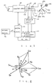
- FIG. 5 1 is a DC current source.
- 2 is an inverter circuit for passing current to stator windings 3U, 3V and 3W of brushless motor 3.
- 4, 5 and 6 are filter curciut that shift by 90 degress the phase of terminal voltages UV, VV, and WV containing the induced voltages generated in stator windings 3U, 3V and 3W.
- 7 is a detection circuit whereby the neutral point voltage NV is obtained from the output signals of these filter circuits 4 to 6.
- 8 9 and 10 are comparators that respectively compare the output signals of filter circuits 4 to 6, which constitute first order delay elements, and neutral point voltage NV.
- 11 is a control circuit.
- Fig. 6 is a time chart showing the operation of the prior art example.
- the terminal voltage UV (see Fig. 6 (a)) generated in stator winding 3U contains a voltage spike that is produced by conduction of the opposite arm return flow diode.
- the terminal voltage UV is shifted in phase by 90 degrees by means of filter circuit 4, producing the phase-shifted voltage DUV as shown in Fig. 6 (b).
- this phase-shifted voltage DUV and the neutral point voltage NV shown in Fig. 6 (b) are compared by comparator 8, to obtain a phase detection signal PSU as shown in Fig. 6C.
- position detection signals PSV and PSW being obtained as shown in Fig. 6(d) and (e) from comparators 9 and 10, based on terminal voltages VV and VW.
- These position detection signals PSU, PSV and PSW are signals that are 120 degrees different in phase for 180 degrees conduction.
- this control circuit 11 is made to produce six commutation signals, which are applied to the bases of the transistors that constitute the switching elements of inverter circuit 2.
- the size of the voltage spike component contained in terminal voltages UV, VV and WV varies depending on the magnitude of the current, i.e., the load of stator windings 3U, 3V and 3W, so if the load fluctuation is large, a phase error is produced in the signal waveform of filter circuits 4 to 6 et seq, causing a stability problem.
- a voltage type PWM inverter 12 consists of a rectifier circuit 14 that rectifies the three-phase AC voltage of three-phase AC power source 13, a smoothing capacitor 15 that smooths this rectified voltage, and a main inverter circuit 16 to which this smoothed DC voltage is applied.
- the AC output voltage from main inverter circuit 16 is then applied to three-phase induction motor 17.
- the current Idc flowing in the DC bus of inverter 12 is detected by current detector 18 and supplied as detection current I to low pass filter (hereinbelow termed "LPF")19.
- LPF low pass filter
- LPF 19 extracts the fundamental wave of the detected current I and outputs it as frequency correction value DELTA f.
- PWM pulse width modulation
- This pulse width modulation control circuit 21 is supplied with a voltage command value V* obtained by converting the frequency command value f* by means of a frequency-voltage (f - V) conversion circuit 22.
- pulse width modulation control circuit 21 performs pulse width modulation control by applying a base signal to the power transistors of main inverter circuit 16, based on reference frequency value f and voltage command value V*.
- the mean value of the current flowing in the DC bus of inverter 12 is proportional to the power supplied to three-phase induction motor 17.
- torque fluctuation is proportional to power fluctuation, so, by controlling the mean current of the DC bus of inverter 12, torque control of three-phase induction motor 17 can be performed, and production of vibration can be prevented.
- the above control device is effective when the speed of revolution of the three phase induction motor 17 is sufficiently high, and the ratio of variation of speed of revolution is very small, in low speed operation, when the speed of revolution is low, the amount of power change for a given change of torque falls off. Even if this is therefore compensated by dividing by the speed of rotation or by the inferred value of the speed of rotation so as to remove dependence on the speed of operation, the lowered S/N ratio means that sufficient accuracy is not obtained. Stable driving of the inverter during low speed operation is therefore difficult.
- This invention was made after consideration of the above circumstances. Its first object is to provide a control device for an AC motor providing good response characteristics and improved stability during sudden accelerations or decelerations and load fluctuations, by controlling the AC motor in accordance with the amount of change of current. Its second object is to provide a control device for an AC motor whereby the AC motor can be driven in a stable manner even during low speed operation.
- a control device for an AC motor comprising inverter means including switching elements whereby DC voltage from DC power source is converted to AC voltage and supplied to said AC motor, characterised by; current detection means for detecting a current supplied from the inverter means to the AC motor; power calculation means for calculating the power passed to said AC motor from a command value and the detection signal of the current detection means; and control means for generating control signals and supplying the signals to the power calculation means and for supplying drive signals based on the signals from the power calculation means to the inverter means.
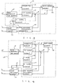
- An inverter circuit 100 consists of a three-phase bridge connection of six switching elements constituted by transistors. This is supplied with the DC voltage of DC power source 101 at its input terminal.
- a three-phase four-pole brushless motor 102 is equipped with a stator 103 provided with U, V and W phase stator coils 103U, 103V and 103W, and with a permanent magnet type rotor 104.
- Stator coils 103U, 103V and 103W are connected in a star connection, which is supplied with AC output voltage from the output terminals of inverter circuit 100 through output leads 105, 106 and 107.
- 108 and 109 are current detectors consisting of Hall current transformers.
- 100 is an amplifier circuit. Together with current detectors 108 and 109, this constitutes a current detection means 111. Current signals Iu and Iv detected by current detectors 108 and 109 are supplied to the input terminals of a power calculating means constituted by power calculation circuit 112 through amplifier circuit 110. As will be described, this power calculation circuit 112 uses current signals Iu and Iv to calculate power signals W1 and W2. These power signals W1 end W2 are output from its output terminal and supplied to the input terminal of a control moans constituted by a control circuit 113.
- This control circuit 113 uses power signals W1 and W2 and a speed command value omega* that is supplied from a setting device 114 to calculate voltage signal V and phase signal ⁇ . These are in turn used to produce six PWM-controlled drive signals DS that are output from its output terminals and supplied to the bases of the six transistors of inverter circuit 100, causing the rotor 104 of brushless motor 102 to rotate with a speed of rotation designated by speed command value omege*.
- Fig. 2 is a vector diagram showing the relationship of the phase voltage, phase current and line voltage in each phase.
- Eu, Ev and Ew are the U, V and W phase voltages
- Iu, Iv and Iw are the U, V and W phase currents
- ⁇ is the phase difference between the respective phase voltages Eu, Ev and Ew and the respective phase currents Iu, Iv and Iw.
- Euw and Evw are the line voltages referred to the W phase voltage Ew.
- Line voltage Euw has a phase difference (- ⁇ /6) with respect to the phase voltage Ev
- the line voltage Evw has a phase difference (+ ⁇ /6) with respect to the phase voltage Ev.
- Speed command value omega* is applied to the respective input terminals of integrating element 116 and V/F control, element 117 through speed adjustment time element 115.
- Integrating element 116 outputs a phase signal from its output terminal and supplies this to the input terminal of drive control element 118.
- V/F control element 117 outputs a voltage command signal V from its output terminal and supplies this to one positive (+) input terminal of an adder 119.
- Adder 119 outputs a voltage signal V from its output terminal, as will be described. This voltage signal V is supplied to the input terminal of drive control element 118, and is also supplied to the input terminal of line voltage calculating element 120.
- Line voltage calculating element 120 receives at its other input terminal a phase signal ⁇ and uses this phase signal ⁇ and voltage signal V to calculate line voltages Euw and Evw, which it supplies as signals to the input terminals of power calculation circuit 112.
- Power signals W1 and W2 from power calculation circuit 112 are respectively supplied to the positive (+) input terminal and negative (-) input terminal of subtractor 121, and the output signal from the output terminal of the subtractor 121 is supplied through a PI (proportional/integral) control element 122 to the other positive (+) input terminal of adder 119.
- control circuit 113 when speed command value omega* is applied to speed adjustment time element 115, the output signal omega* of speed adjustment time element 115 rises for a speed adjustment time that can be specified at will by speed command value omega*. This is then integrated by integrating element 116 and output as phase signal ⁇ . It is also compared with a V/F pattern, which can be chosen at will, by V/F control element 117, and output as voltage command signal V. The voltages to be applied to stator coils 113U and 113W can then be calculated from the Phase signal ⁇ that is output from integrating element 116 and the voltage signal V that is output from adder 119 that adds a correction to voltage command signal V.
- Line voltago calculating element 120 calculates these as line voltages Euw and Evw and applies them as signals to power calculation circuit 112.
- Power calculation circuit 112 calculates powers W1 and W2 as shown by equations (24) and (25) from the phase current signals Iu and Iv that are supplied from current detection means 111 and these line voltages Euw and Evw. These powers W1 and W2 are then fed back to control circuit 113 as signals and supplied to subtractor 121.
- Subtractor 121 finds the difference between these poker signals W1 and W2 and supplies this difference signal to PI control element 122.
- PI control element 122 performs PI control such that this difference signal is zero or a prescribed value, its output being supplied to adder 119.
- Adder 119 outputs a voltage signal v by adding the output signal from PI control element 122 to voltage command signal V.
- the phase signal ⁇ and voltage signal v which are thus obtained are supplied to drive control element 118.
- Drive control element 118 uses this phase signal ⁇ and voltage signal v to output drive signals DS which it supplies to the bases of the six transistors of inverter circuit 100, thereby causing the rotor 104 of brushless motor 102 to rotate at a speed corresponding to the speed command value omega*.
- the currents flowing in the U phase and V phase stator coils 103U and 103V are detected by current detection means 111, and these detected current signals Iu and Iv are used by the power calculation circuit 112 to calculate powers W1 and W2.
- Control circuit 113 then obtains a voltage signal v and phase signal ⁇ by PI control such that the difference of the powers W1 and W2 obtained as a result of this calculation is zero or a prescribed value.
- This voltage signal v and phase signal ⁇ are then in turn used by inverter circuit 100 to control operation of the brushless motor 102.
- a first order delay element constituted by a filter circuit. This results in good response to abrupt accelerations or decelerations and load fluctuations, and enables stability to be raised.
- this embodiment has excellent response to external disturbances, detection is possible in the low speed region, and the range of control can be increased.
- Fig. 4 shows another embodiment of this invention. Parts which are the same as in Fig. 3 are given the same refernce numerals. The difference with respect to Fig. 3 lies in that control circuit 113 is additionally provided with an adder 123 and P control elemet (or it could be a PI control element) 124. A phase signal ⁇ from integrating element 116 is applied to one of the positive (+) input terminals of adder 123, and a difference signal from adder 121 is applied to the other positive (+) input terminal of adder 123 through P control element 124, so that a phase signal ⁇ is output from the output terminal of adder 123.
- control circuit 113 is additionally provided with an adder 123 and P control elemet (or it could be a PI control element) 124.
- a phase signal ⁇ from integrating element 116 is applied to one of the positive (+) input terminals of adder 123, and a difference signal from adder 121 is applied to the other positive (+) input terminal of adder 123 through P
Applications Claiming Priority (3)
| Application Number | Priority Date | Filing Date | Title |
|---|---|---|---|
| JP292839/89 | 1989-11-10 | ||
| JP1292839A JPH03155392A (ja) | 1989-11-10 | 1989-11-10 | 電流検出装置 |
| EP90312301A EP0427571B1 (fr) | 1989-11-10 | 1990-11-09 | Régulation d'un moteur à courant alternatif |
Related Parent Applications (1)
| Application Number | Title | Priority Date | Filing Date |
|---|---|---|---|
| EP90312301.6 Division | 1990-11-09 |
Publications (3)
| Publication Number | Publication Date |
|---|---|
| EP0629038A2 true EP0629038A2 (fr) | 1994-12-14 |
| EP0629038A3 EP0629038A3 (fr) | 1995-03-29 |
| EP0629038B1 EP0629038B1 (fr) | 1997-10-08 |
Family
ID=17787029
Family Applications (1)
| Application Number | Title | Priority Date | Filing Date |
|---|---|---|---|
| EP94202372A Expired - Lifetime EP0629038B1 (fr) | 1989-11-10 | 1990-11-09 | Régulation d'un moteur à courant alternatif |
Country Status (5)
| Country | Link |
|---|---|
| US (1) | US5206575A (fr) |
| EP (1) | EP0629038B1 (fr) |
| JP (1) | JPH03155392A (fr) |
| KR (1) | KR940006168B1 (fr) |
| DE (2) | DE69031573T2 (fr) |
Cited By (1)
| Publication number | Priority date | Publication date | Assignee | Title |
|---|---|---|---|---|
| EP0684694A2 (fr) * | 1994-05-26 | 1995-11-29 | AlliedSignal Inc. | Commande du facteur de puissance d'un moteur à aimants permanents alimenté par un convertisseur à modulation de largeur d'impulsions |
Families Citing this family (44)
| Publication number | Priority date | Publication date | Assignee | Title |
|---|---|---|---|---|
| JPH0638575A (ja) * | 1992-07-17 | 1994-02-10 | Honda Motor Co Ltd | 交流電動機のトルク制御装置 |
| JPH0654586A (ja) * | 1992-07-28 | 1994-02-25 | Fuji Electric Co Ltd | 同期電動機駆動用インバータの瞬停再起動装置 |
| JPH06233408A (ja) * | 1993-02-02 | 1994-08-19 | Honda Motor Co Ltd | 電動車用モータ給電装置 |
| DE69432554T2 (de) * | 1993-12-28 | 2004-03-25 | Sanyo Electric Co., Ltd., Moriguchi | Klimaanlage und zugehöriger Schaltkreis für den Inverter |
| GB9508051D0 (en) * | 1995-04-20 | 1995-06-07 | Switched Reluctance Drives Ltd | Compensation for input voltage variation in an electric motor drive |
| US5670859A (en) * | 1995-06-23 | 1997-09-23 | General Resource Corporation | Feedback control of an inverter output bridge and motor system |
| JP2857094B2 (ja) * | 1995-12-28 | 1999-02-10 | 株式会社東芝 | 三相整流装置 |
| US5808880A (en) * | 1996-08-30 | 1998-09-15 | Otis Elevator Company | Power factor controller for active converter |
| JP2000092881A (ja) * | 1998-09-18 | 2000-03-31 | Yaskawa Electric Corp | 電動機制御装置 |
| US6442979B1 (en) * | 1999-05-06 | 2002-09-03 | Emerson Electric Co. | Washing machine motor control device and method |
| US6400107B1 (en) * | 1999-08-04 | 2002-06-04 | Sharp Kabushiki Kaisha | Motor control device capable of driving a synchronous motor with high efficiency and high reliability |
| US6366049B1 (en) * | 2000-05-10 | 2002-04-02 | Ecostar Electric Drive Systems L.L.C. | Motor starter and speed controller system |
| US6531842B2 (en) | 2001-06-25 | 2003-03-11 | Schlumberger Technology Corp. | Sine wave variable speed drive |
| JP4377091B2 (ja) * | 2001-07-27 | 2009-12-02 | 株式会社日立産機システム | インバータ装置、及びその交流電流検出方法 |
| JP5124899B2 (ja) * | 2001-09-28 | 2013-01-23 | ダイキン工業株式会社 | モータ制御方法およびその装置 |
| ES2425988T3 (es) * | 2001-09-29 | 2013-10-18 | Daikin Industries, Ltd. | Procedimiento para la detección de la corriente de fase, procedimiento de control de inversor, procedimiento de control de motor y aparatos utilizados en estos procedimientos |
| JP2004289985A (ja) * | 2003-03-25 | 2004-10-14 | Matsushita Electric Ind Co Ltd | モータ駆動用インバータ制御装置および空気調和機 |
| JP3955285B2 (ja) * | 2003-03-27 | 2007-08-08 | 松下電器産業株式会社 | モータ駆動用インバータ制御装置および空気調和機 |
| JP3955286B2 (ja) * | 2003-04-03 | 2007-08-08 | 松下電器産業株式会社 | モータ駆動用インバータ制御装置および空気調和機 |
| GB2410848A (en) * | 2004-02-05 | 2005-08-10 | Dyson Ltd | Voltage compensation in switched reluctance motor |
| GB2410847A (en) * | 2004-02-05 | 2005-08-10 | Dyson Ltd | Control of motor winding energisation according to rotor angle |
| US20060038530A1 (en) * | 2004-07-07 | 2006-02-23 | Rt Patent Company, Inc. | System and method for optimizing motor performance by varying flux |
| US7026785B1 (en) * | 2004-07-07 | 2006-04-11 | Rt Patent Company, Inc. | Motor controller |
| US7116029B2 (en) * | 2004-07-19 | 2006-10-03 | Rt Patent Company, Inc. | AC induction motor having multiple poles and increased stator/rotor gap |
| US20060208603A1 (en) * | 2005-03-18 | 2006-09-21 | Rt Patent Company, Inc. | Rotating electric machine with variable length air gap |
| US7932693B2 (en) * | 2005-07-07 | 2011-04-26 | Eaton Corporation | System and method of controlling power to a non-motor load |
| JP4847060B2 (ja) * | 2005-07-15 | 2011-12-28 | 日立オートモティブシステムズ株式会社 | 交流モータ駆動装置及びその制御方法 |
| US20070132331A1 (en) * | 2005-12-13 | 2007-06-14 | Rt Patent Company, Inc. | DC homopolar motor/generator |
| US20070132334A1 (en) * | 2005-12-14 | 2007-06-14 | Rt Patent Company, Inc. | Systems and methods for providing electrical contact with a rotating element of a machine |
| US7683568B2 (en) * | 2007-09-28 | 2010-03-23 | Rockwell Automation Technologies, Inc. | Motor drive using flux adjustment to control power factor |
| CN101436773B (zh) * | 2007-11-15 | 2012-10-03 | 上海华建电力设备股份有限公司 | 一种电动机再起动的方法 |
| US7893650B2 (en) * | 2008-01-29 | 2011-02-22 | Azure Dynamics, Inc. | Method and system for multiphase current sensing |
| WO2011016214A1 (fr) * | 2009-08-04 | 2011-02-10 | パナソニック株式会社 | Dispositif de conversion d'énergie et dispositif de chauffage par induction |
| JP5863367B2 (ja) * | 2011-10-04 | 2016-02-16 | 三菱重工業株式会社 | インバータ装置 |
| US20130088903A1 (en) * | 2011-10-11 | 2013-04-11 | Hamilton Sundstrand Corporation | Control architecture for a multi-level active rectifier |
| US9800139B2 (en) * | 2014-07-15 | 2017-10-24 | Nidec Motor Corporation | Motor control system and method for input current protection |
| US20160020720A1 (en) * | 2014-07-15 | 2016-01-21 | IPH + Limited | Drive control system and drive control method |
| JP6365315B2 (ja) * | 2015-01-16 | 2018-08-01 | 株式会社デンソー | モータ始動装置、モータ始動方法 |
| JP6358144B2 (ja) * | 2015-03-26 | 2018-07-18 | 株式会社豊田自動織機 | 制御装置及び車載用電動圧縮機 |
| EP3342037A1 (fr) * | 2015-08-29 | 2018-07-04 | ABB Schweiz AG | Système ayant une machine électrique et un dispositif de commande |
| JP6699385B2 (ja) * | 2016-06-17 | 2020-05-27 | 株式会社デンソー | 電力変換装置 |
| CN106411151A (zh) * | 2016-08-29 | 2017-02-15 | 施电气科技(上海)有限公司 | 高效绝缘栅双极igbt结构变频器 |
| KR102019827B1 (ko) * | 2018-02-01 | 2019-09-09 | 엘에스산전 주식회사 | 인버터 |
| EP3857699A1 (fr) * | 2018-09-28 | 2021-08-04 | Innovative Power Solutions, LLC | Commande de processus utilisant une boucle de commande d'amplitude |
Citations (1)
| Publication number | Priority date | Publication date | Assignee | Title |
|---|---|---|---|---|
| JPS59216493A (ja) * | 1983-05-20 | 1984-12-06 | Toshiba Corp | 周波数変換装置 |
Family Cites Families (10)
| Publication number | Priority date | Publication date | Assignee | Title |
|---|---|---|---|---|
| US3723840A (en) * | 1972-01-21 | 1973-03-27 | Power Control Corp | Apparatus for motor current minimization |
| US3819992A (en) * | 1972-01-21 | 1974-06-25 | Power Control Corp | Method and apparatus for providing efficient and stable power inversion with voltage and frequency control |
| US4291264A (en) * | 1979-09-04 | 1981-09-22 | Borg-Warner Corporation | Power factor control system for inverter-driven a-c induction motor |
| US4420718A (en) * | 1980-12-05 | 1983-12-13 | Hitachi, Ltd. | Control system for induction motor using inverter for AC power supply |
| US4590413A (en) * | 1982-01-11 | 1986-05-20 | Eaton Corporation | EV drivetrain inverter with V/HZ optimization |
| WO1984002404A1 (fr) * | 1982-12-11 | 1984-06-21 | Fairford Electronics Ltd | Procede et appareil de reglage automatique de la demande du signal d'entree d'un retard de phase dans un controleur de facteur de puissance d'un moteur a induction |
| JPS59139893A (ja) * | 1983-01-31 | 1984-08-10 | Shinpo Kogyo Kk | 誘導電動機制御装置 |
| DE3307623C2 (de) * | 1983-03-04 | 1986-06-05 | Lenze GmbH & Co KG Aerzen, 3258 Aerzen | Verfahren und Schaltungsanordnung zur Regelung eines Wechselstrom- oder Drehstrommotors |
| US5010287A (en) * | 1988-02-24 | 1991-04-23 | Matsushita Electric Works, Ltd. | Induction motor control system |
| JP2712470B2 (ja) * | 1989-01-23 | 1998-02-10 | 松下電器産業株式会社 | インバータ装置の電流検出装置 |
-
1989
- 1989-11-10 JP JP1292839A patent/JPH03155392A/ja active Pending
-
1990
- 1990-11-09 DE DE69031573T patent/DE69031573T2/de not_active Expired - Fee Related
- 1990-11-09 EP EP94202372A patent/EP0629038B1/fr not_active Expired - Lifetime
- 1990-11-09 DE DE69023096T patent/DE69023096T2/de not_active Expired - Fee Related
- 1990-11-09 US US07/610,248 patent/US5206575A/en not_active Expired - Fee Related
- 1990-11-10 KR KR1019900018165A patent/KR940006168B1/ko not_active IP Right Cessation
Patent Citations (1)
| Publication number | Priority date | Publication date | Assignee | Title |
|---|---|---|---|---|
| JPS59216493A (ja) * | 1983-05-20 | 1984-12-06 | Toshiba Corp | 周波数変換装置 |
Non-Patent Citations (1)
| Title |
|---|
| PATENT ABSTRACTS OF JAPAN vol. 9, no. 85 (E-308) 13 April 1985 & JP-A-59 216 493 (TOSHIBA K.K) 6 December 1984 * |
Cited By (2)
| Publication number | Priority date | Publication date | Assignee | Title |
|---|---|---|---|---|
| EP0684694A2 (fr) * | 1994-05-26 | 1995-11-29 | AlliedSignal Inc. | Commande du facteur de puissance d'un moteur à aimants permanents alimenté par un convertisseur à modulation de largeur d'impulsions |
| EP0684694A3 (fr) * | 1994-05-26 | 1996-10-16 | Allied Signal Inc | Commande du facteur de puissance d'un moteur à aimants permanents alimenté par un convertisseur à modulation de largeur d'impulsions. |
Also Published As
| Publication number | Publication date |
|---|---|
| DE69023096D1 (de) | 1995-11-23 |
| DE69023096T2 (de) | 1996-05-09 |
| EP0629038A3 (fr) | 1995-03-29 |
| US5206575A (en) | 1993-04-27 |
| KR940006168B1 (ko) | 1994-07-08 |
| JPH03155392A (ja) | 1991-07-03 |
| DE69031573D1 (de) | 1997-11-13 |
| DE69031573T2 (de) | 1998-02-19 |
| EP0629038B1 (fr) | 1997-10-08 |
| KR910010823A (ko) | 1991-06-29 |
Similar Documents
| Publication | Publication Date | Title |
|---|---|---|
| EP0629038B1 (fr) | Régulation d'un moteur à courant alternatif | |
| US6262555B1 (en) | Apparatus and method to generate braking torque in an AC drive | |
| US4767976A (en) | Control system for PWM inverter | |
| JP4022630B2 (ja) | 電力変換制御装置、電力変換制御方法、および電力変換制御用プログラム | |
| US3919609A (en) | Method and circuit for reducing the torque ripple of a rotating-field machine | |
| KR900001790B1 (ko) | 전동기 구동용 전원장치 | |
| EP0279415A1 (fr) | Appareil de régulation pour un moteur à induction | |
| JPH03128691A (ja) | 電圧形pwmコンバータ・インバータシステムとその制御方式 | |
| US7187155B2 (en) | Leakage inductance saturation compensation for a slip control technique of a motor drive | |
| KR880001837B1 (ko) | 유도 전동기 구동방식 | |
| JPH1023756A (ja) | 電圧形インバータ装置及びその制御方法 | |
| US5923144A (en) | Frequency generator for a motor controller | |
| JP3773794B2 (ja) | 電力変換装置 | |
| JP3333442B2 (ja) | ブラシレスモータの駆動装置 | |
| JPS58141699A (ja) | 電動機制御装置 | |
| JPH1080180A (ja) | 同期電動機の制御方法及び装置 | |
| JPH05103498A (ja) | 電動機制御装置 | |
| JPS6038960B2 (ja) | インバ−タの電圧制御装置 | |
| EP0427571B1 (fr) | Régulation d'un moteur à courant alternatif | |
| JPH03253291A (ja) | 電動機駆動装置 | |
| JPH07236294A (ja) | インバータ装置 | |
| JP3124019B2 (ja) | 誘導電動機の制御装置 | |
| JPH1189237A (ja) | インバ−タの制御方法及びインバ−タ装置 | |
| JP2677686B2 (ja) | ブラシレスモータの駆動装置 | |
| JP3815584B2 (ja) | センサレス同期モータの駆動装置 |
Legal Events
| Date | Code | Title | Description |
|---|---|---|---|
| PUAI | Public reference made under article 153(3) epc to a published international application that has entered the european phase |
Free format text: ORIGINAL CODE: 0009012 |
|
| 17P | Request for examination filed |
Effective date: 19940819 |
|
| AC | Divisional application: reference to earlier application |
Ref document number: 427571 Country of ref document: EP |
|
| AK | Designated contracting states |
Kind code of ref document: A2 Designated state(s): DE FR SE |
|
| PUAL | Search report despatched |
Free format text: ORIGINAL CODE: 0009013 |
|
| AK | Designated contracting states |
Kind code of ref document: A3 Designated state(s): DE FR SE |
|
| 17Q | First examination report despatched |
Effective date: 19960701 |
|
| GRAG | Despatch of communication of intention to grant |
Free format text: ORIGINAL CODE: EPIDOS AGRA |
|
| GRAH | Despatch of communication of intention to grant a patent |
Free format text: ORIGINAL CODE: EPIDOS IGRA |
|
| GRAH | Despatch of communication of intention to grant a patent |
Free format text: ORIGINAL CODE: EPIDOS IGRA |
|
| GRAA | (expected) grant |
Free format text: ORIGINAL CODE: 0009210 |
|
| AC | Divisional application: reference to earlier application |
Ref document number: 427571 Country of ref document: EP |
|
| AK | Designated contracting states |
Kind code of ref document: B1 Designated state(s): DE FR SE |
|
| ET | Fr: translation filed | ||
| REF | Corresponds to: |
Ref document number: 69031573 Country of ref document: DE Date of ref document: 19971113 |
|
| PLBE | No opposition filed within time limit |
Free format text: ORIGINAL CODE: 0009261 |
|
| STAA | Information on the status of an ep patent application or granted ep patent |
Free format text: STATUS: NO OPPOSITION FILED WITHIN TIME LIMIT |
|
| 26N | No opposition filed | ||
| REG | Reference to a national code |
Ref country code: FR Ref legal event code: D6 |
|
| PGFP | Annual fee paid to national office [announced via postgrant information from national office to epo] |
Ref country code: SE Payment date: 19991104 Year of fee payment: 10 |
|
| PGFP | Annual fee paid to national office [announced via postgrant information from national office to epo] |
Ref country code: FR Payment date: 19991109 Year of fee payment: 10 |
|
| PGFP | Annual fee paid to national office [announced via postgrant information from national office to epo] |
Ref country code: DE Payment date: 19991115 Year of fee payment: 10 |
|
| PG25 | Lapsed in a contracting state [announced via postgrant information from national office to epo] |
Ref country code: SE Free format text: THE PATENT HAS BEEN ANNULLED BY A DECISION OF A NATIONAL AUTHORITY Effective date: 20001129 |
|
| EUG | Se: european patent has lapsed |
Ref document number: 94202372.2 |
|
| PG25 | Lapsed in a contracting state [announced via postgrant information from national office to epo] |
Ref country code: FR Free format text: LAPSE BECAUSE OF NON-PAYMENT OF DUE FEES Effective date: 20010731 |
|
| PG25 | Lapsed in a contracting state [announced via postgrant information from national office to epo] |
Ref country code: DE Free format text: LAPSE BECAUSE OF NON-PAYMENT OF DUE FEES Effective date: 20010801 |
|
| REG | Reference to a national code |
Ref country code: FR Ref legal event code: ST |