EP0626472B2 - Dispositif pour mesurer l'épaisseur d'une matière fibreuse avec un guide-mèche pour guider la mèche à l'entrée du système d'étirage - Google Patents
Dispositif pour mesurer l'épaisseur d'une matière fibreuse avec un guide-mèche pour guider la mèche à l'entrée du système d'étirage Download PDFInfo
- Publication number
- EP0626472B2 EP0626472B2 EP94104052A EP94104052A EP0626472B2 EP 0626472 B2 EP0626472 B2 EP 0626472B2 EP 94104052 A EP94104052 A EP 94104052A EP 94104052 A EP94104052 A EP 94104052A EP 0626472 B2 EP0626472 B2 EP 0626472B2
- Authority
- EP
- European Patent Office
- Prior art keywords
- feeler element
- sliver guide
- slivers
- rollers
- fibre
- Prior art date
- Legal status (The legal status is an assumption and is not a legal conclusion. Google has not performed a legal analysis and makes no representation as to the accuracy of the status listed.)
- Expired - Lifetime
Links
Images


Classifications
-
- G—PHYSICS
- G01—MEASURING; TESTING
- G01B—MEASURING LENGTH, THICKNESS OR SIMILAR LINEAR DIMENSIONS; MEASURING ANGLES; MEASURING AREAS; MEASURING IRREGULARITIES OF SURFACES OR CONTOURS
- G01B7/00—Measuring arrangements characterised by the use of electric or magnetic techniques
- G01B7/12—Measuring arrangements characterised by the use of electric or magnetic techniques for measuring diameters
- G01B7/125—Measuring arrangements characterised by the use of electric or magnetic techniques for measuring diameters of objects while moving
-
- D—TEXTILES; PAPER
- D01—NATURAL OR MAN-MADE THREADS OR FIBRES; SPINNING
- D01H—SPINNING OR TWISTING
- D01H13/00—Other common constructional features, details or accessories
- D01H13/14—Warning or safety devices, e.g. automatic fault detectors, stop motions ; Monitoring the entanglement of slivers in drafting arrangements
- D01H13/22—Warning or safety devices, e.g. automatic fault detectors, stop motions ; Monitoring the entanglement of slivers in drafting arrangements responsive to presence of irregularities in running material
-
- G—PHYSICS
- G01—MEASURING; TESTING
- G01B—MEASURING LENGTH, THICKNESS OR SIMILAR LINEAR DIMENSIONS; MEASURING ANGLES; MEASURING AREAS; MEASURING IRREGULARITIES OF SURFACES OR CONTOURS
- G01B7/00—Measuring arrangements characterised by the use of electric or magnetic techniques
- G01B7/02—Measuring arrangements characterised by the use of electric or magnetic techniques for measuring length, width or thickness
- G01B7/06—Measuring arrangements characterised by the use of electric or magnetic techniques for measuring length, width or thickness for measuring thickness
- G01B7/10—Measuring arrangements characterised by the use of electric or magnetic techniques for measuring length, width or thickness for measuring thickness using magnetic means, e.g. by measuring change of reluctance
- G01B7/107—Measuring arrangements characterised by the use of electric or magnetic techniques for measuring length, width or thickness for measuring thickness using magnetic means, e.g. by measuring change of reluctance for measuring objects while moving
Definitions
- the invention relates to a device for measurement the strength of a fiber structure with a tape guide to guide the slivers at the drafting system inlet, whose walls are at least partially conical, the merging incoming slivers in one plane are formed and arranged after the pair of rollers after the slivers run apart again, where a burdened, portable Touch element is present, that with a stationary counter surface a bottleneck for the continuous, from Existing fiber band forms and its change of position with different strength of the Fiber dressing on a converter device for generation a control impulse acts.
- a device for guiding the tapes on Drafting system inlet available includes a tapered support plate for the slivers with laterally curved wall surfaces, to which the Belt guide with rectangular entry cross-section, flat top and bottom surfaces and tapered side surfaces is.
- the incoming slivers arranged side by side slide over the support plate and bottom wall the support surface formed away from the tape guide. Between the incoming slivers and there is a gap between the side walls in the inlet area available.
- the tape guide lies immediately in front of a pair of draw rollers, the parallel one Axes are aligned vertically.
- the pair of rollers also serves to measure one in a given one Tolerance range lying thickness of the fiber structure and is dependent on the thickness of the measured
- the fiber structure is arranged to be adjustable in distance.
- the movable, spring-loaded roller as a loaded, portable probe is in relation to the stationary roller can be changed in the horizontal direction.
- the stationary roller consists of three disks, the middle one has a smaller diameter than the two outer, whereby the peripheral surface as Groove is formed (grooved roller).
- the movable roller (Spring roller) consists of a disc that fits with your Circumferential area engages in the groove of the stationary roller.
- the peripheral surface of the central disk of the grooved roller forms the stationary counter surface for the peripheral surface the movable spring roller.
- the tongue and groove design is essentially rectangular Constriction formed between which the fiber structure from compressed fiber bands for measurement is passed through.
- the individual belts run during operation at the drafting system inlet at a speed z. B. of 150 m / min in the tape guide through the conical tapering training of the tape guide the slivers side by side in a plane merged without clamping.
- the one from the tape guide emerging slivers are only through compresses the feed into the subsequent nip, d. h compressed to the cross section of the substance and especially the air squeezed out, so that a measurement
- the peripheral speed of the Rolls and the belt running speed are included same, so that no relative speed between the rollers and the slivers.
- DE-A-39 13 548 describes a device for measuring the thickness of a single sliver with a belt funnel at the exit of a card.
- the Document does not disclose any tape guidance at the drafting system entrance, but a band funnel, both of them make a significant difference in terms of design and function. Due to the circular belt funnel, only one carding belt becomes carried out. Due to the conical, frustoconical shape on all sides circular inner wall surface and the The card sliver becomes the narrow exit of the funnel heavily compressed.
- the take-off rollers are used for the take-off one card sliver from the sliver funnel. Within of the ribbon funnel rubs the only card sliver on all sides on the inner wall surface of the belt funnel.
- the invention has for its object a device to create the type described at the beginning, which avoids the disadvantages mentioned, in particular is structurally simple and an improved measurement of the fiber structure at the drafting system inlet.
- the slivers are already compressed in the sliver guide and scanned so that the downstream of the tape guide Roll the already scanned fiber structure just pull it off. Allow these measures a separation of functions in that the take-off rollers upstream probe element in a simple way the slivers are compressed and scanned at the same time.
- the downstream rollers can be characterized in that they only are still take-off rollers, constructive and assembly be made much easier. In particular by eliminating the measuring function, the at the known device existing considerable Problems and the effort in the measurement avoided. In this way, the slivers experience a stepped Treatment related to that for one scan required compression and with regard to the deduction required compression.
- Device created that is constructive and assembly is significantly simplified and improved Measurement of the fiber structure at the drafting system inlet allowed.
- the movable probe element is preferably the Band guidance in the area of the side by side in the narrow point merged slivers assigned and has a sliding surface that the slivers side by side compacting against the stationary counter surface the belt guide presses and the pair of rollers in the narrowed compressed fiber slivers subtracts side by side.
- the distance is advantageous (a) between the movable probe element and the clamping point of the pair of rollers equal or less than the staple length of the fiber material. Is expedient the distance (b) between the exit of the tape guide and the nip point of the pair of rollers or less than the staple length of the fiber material.
- P refer the probe element is horizontal and right-angled movable with respect to the tape running direction.
- the probe element is vertical and at right angles movable in the direction of the tape.
- the tape guide has at least one opening, whereby the sensing element passes through the opening.
- Prefers is the exit of the tape guide immediately before the Nip of the take-off rollers.
- the bottleneck is advantageous immediately before the exit of the tape guide arranged.
- the pull-off force is expediently higher than the measuring force.
- the opening is preferably a recess.
- the recess is advantageously approximately rectangular.
- the probe element is expediently an approximately rectangular one Sensing element, whose long edges in the width direction and its short edges run in the working direction.
- the outer end of the probe element is preferably small Distance to the exit of the tape guide in the direction arranged on the take-off rollers.
- the probe element is mounted on a fixed pivot bearing.
- a lever of the pivot bearing is useful a force element, e.g. B. counterweight, spring or the like, together.
- the feeler element is preferably horizontal Movable direction.
- the probe element is advantageous spring-loaded at one end.
- the probe element on a holding member is expedient, e.g. B. lever, stored.
- the probe element is preferably around a vertical axis rotatably mounted.
- the probe element has at least one inductive measuring element with plunger core and plunger.
- the measuring element is a non-contact analog working Distance sensor, e.g. inductive proximity initiator.
- a stop is preferably assigned to the feeler element.
- the probe element is advantageous by at least a force loaded and supported.
- the constriction in the manner of a photo aperture, i.e. as Aperture formed with inner sliding surfaces.
- the movably mounted probe element advantageously penetrates a corresponding breakthrough in the wall the tape guide and loaded with a sliding surface respective fiber structure up to close to the substance cross section.
- the constriction preferably faces two to one another parallel surfaces between which a part of the movably mounted probe element is fitted.
- Advantageous runs the movable probe element opposite wall at right angles to the parallel surfaces.
- the preload is expediently carried out of the movably mounted probe element by mechanical electrical, hydraulic or pneumatic Means, e.g. B. springs, weights, self-suspension, load cylinder, Magnets or the like which are adjustable can.
- the movably mounted probe element is preferred formed as an angle lever, the approximately at the break point is stored in the recess of the band guide, either the angle lever or the tape guide is stationary and the angle lever is spring-loaded is.
- the spring loading the bell crank is advantageous with its free end on a finely adjustable Abutment.
- the axes of the take-off rollers are expedient arranged horizontally. Those are preferred Axes of the take-off rollers arranged vertically.
- Advantageous is another tape guide upstream of the tape guide, being the area between the two Belt guides with the outside air over at least one Opening communicates.
- the Belt guide at least one vent opening.
- the output of the tape guide preferably has one Rectangular cross section.
- the exit is expediently sufficient the belt guide into the nip between the take-off rollers.
- the side walls are preferred the wall guide tapers conically in the direction of tape travel educated.
- the bottom wall is advantageous and the top wall of the tape guide in the tape running direction tapered.
- the one opposite the probe element is expedient stationary wall element z. B. by an adjusting screw changeable.
- the probe element is preferred trapezoidal.
- the sliding surface is advantageous of the probe element is convexly curved or rounded. Appropriately go the inner surface of the side wall the tape guide and the feeler element are flush with each other about. Preference is given to the individual thickness Slivers formed an average. That is advantageous stationary counter surface a sliding surface on which the slivers slide along.
- the sliding surface is useful of the feeler element straight in the longitudinal direction.
- the belt guide is preferably a pair of squeeze rollers upstream.
- the tape guide is advantageous the first pair of drafting rollers connected downstream as take-off rollers.
- the delivery speed is expedient approx. 150 m / min.
- the pull-off force of the pull-off rollers is preferred higher than the clamping force at the narrow point.
- the clamping force is advantageously less than the tearing force.
- At least the top surface of the tape guide is expedient can be opened and closed.
- the top surface is preferred attached to a swivel. That is advantageous A pair of cylindrical calender rolls.
- a device for measuring the Thickness of a fiber structure with a tape guide to guide the slivers at the drafting system inlet which has a top and bottom surface and its side walls conical
- the slivers coming in side by side leading side by side in one level are trained and a pair of rollers is downstream after the sliver again diverge side by side
- a stressed, portable probe element is present, that with a fixed counter surface is a constriction for the continuous, consisting of slivers Forms fiber structure and its change in position at different Strength of the fiber structure on one Converter device for generating a control pulse acts, the movable feeler of the tape guide in the area of the merged side by side in the constriction Assigned slivers and points a sliding surface on which the slivers side by side compacting against the stationary counter surface of the Belt guide presses and the pair of rollers pulls in the Narrowed, compressed, scanned slivers side by side.
- the edges are preferred deburred from the tape guide.
- the tape guide is advantageous a casting. Appropriately point out the sliver contact surfaces of the Belt guide has a low coefficient of friction.
- Prefers indicates the one in contact with the sliver Sliding surface of the probe element has a low coefficient of friction
- the tape guide is advantageous at least in the area of the contact surfaces enamelled. It is useful Enameled sliding surface of the probe element.
- the band guide made of a ceramic.
- the ceramic is advantageously a sintered ceramic.
- the ceramic is an oxide ceramic.
- the band guide made of metal. They are advantageous Polished contact surfaces.
- the contact surfaces are expedient hardened.
- the contact surfaces preferably exist from hard material inserts.
- the citation advantageously shows a substantially rectangular cross section in the Constriction.
- the cross section expediently tapers towards the sensing element. Is preferred at least one of those limiting the cross section Walls to taper the cross section to the opposite Wall inclined.
- the tape guide advantageously has essentially the shape of a truncated pyramid on.
- the sensing element expediently passes through one Narrow side of the tape guide.
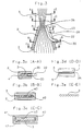
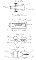
- Figure 1a shows a high performance line from the company Trützschler, for example the high-performance line HS 900 schematically as a side view.
- the slivers 3 kick coming from cans not shown, into the band guide 2 and are pulled through the take-off rollers 4,5 transported past the measuring element 6.
- the drafting system 1 consists essentially of the upper drafting roller 7 and the lower Drafting system inlet roller 8, the pre-stretching area 9 with the pre-stretch top roller 10 and the pre-stretch bottom roller 11 are assigned. Between the Pre-stretch top roll 10 with the pre-stretch bottom roll 11 and the main stretching top roller 13 and the Main stretching lower roller 15 is the main stretching area 12.
- the main draw lower roll 15 a second main stretching top roller 14 is assigned. So it is a four over three stretching system.
- the stretched slivers 3 reach after Pass the main stretching upper roller 14 through the fleece guide 16 and are by means of the delivery rollers 18, 18 ' pulled through the band hopper 17 to a single one Volume summarized and in cans, not shown filed.
- the computer 21 go through that Measuring element 6 on the tape guide 2 signals determined a and are implemented in commands that the control motor 20 control the upper take-off roller 4, the lower one Take-off roller 5 and the rollers of the pre-stretching area 9, so the drafting roller top roller 7, the Drafting unit inlet lower roller 8, the pre-stretching upper roller 10 and the Vorverstreckunterwalze 11 drives.
- the measuring element 6 Values of the incoming amount of fibers from the slivers 3 the fluctuations that occur controlled via the computer 21 by means of the control motor 20 by changing the roller speeds adjusted on the rollers 4, 5, 7, 8 10, 11.
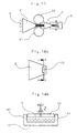
- the top view of the feed area is the upper take-off roller 4 for clarity not shown.
- the slivers 3 are in the Band guide 2 merged, the measuring element 6 designed as a probe element 22, which in a pivot bearing 30 is mounted and has two legs. The one Leg is engaged with the slivers 3, the other legs, the lever 31 will be replaced later forces to be explained.
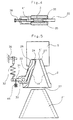
- Fig. 2 the side view of the catchment area in Partial section, shows how the individual fiber strands 3 in the Band guide 2 merged side by side and at the narrow point 23 of the tape guide 2 are scanned by means of the sensing element 22.
- the Probe element 22 is mounted in a rotary bearing 30 acted on the lever 31 by a tension spring 32 and is also connected to a measuring element 48 which executed in the present case as a moving coil instrument is. Changes in the amount of fiber supplied Sliver 3 are thereby a change in volume detected.
- the take-off rollers 4 are and 5 arranged vertically, i.e. that is, the slivers 3 one above the other in the nip 26 of the rollers 4, 5 break in.
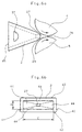
- the cuts made by Fig. 3 are in the 3a to 3e shown. 3c, run eight slivers 3 in the tape guide 2, the through the side walls 40, 41, the ceiling 43 and the Floor 42 is limited. Between the slivers 3, the side walls 40, 41 and the ceiling 43 is still a lot of free space, that is, air caused by the tapering of the walls 40, 41, 42, 43, as shown in FIG. 3b, considerably is reduced.
- FIG. 3a shows the section through the constriction 23, that is the area where floor 42 and ceiling 43 run parallel and the sensing element 22 with its sliding surface 34 the adjacent slivers 3 against the Counter surface 41 presses.
- Pull the take-off rollers 4, 5 which compresses slivers 3 through the sliver guide exit 27.
- the pressure between the rollers 4, 5 takes place in the clamping point 26, which is the section dd in Fig. 3d is shown. At this point is the greatest compression the slivers 3 reached. Then fan they again in individual slivers 3, as in Fig. 3e Section ee shown on.
- FIG. 4 shows a special embodiment and as such also the one already shown in FIG. 3a Constriction 23.
- ceiling 43 is also here and bottom 42 designed as parallel surfaces 35.
- the sensing element 22 which the recess 28 in the Narrow side of the belt guide 2 in the present case, So extends through the side 40, stored in the pivot bearing 30.
- Deviating from these identical embodiments 4 shows, however, that the counter surface 41, that is to say the one opposite the sensing element 22 Wall of the band guide, in the area of the narrow point 23 is adjustable. The adjustment can done by the adjusting screw 38.
- Fig. 5 shows the series connection of two Band guides 2, 2 '.
- the slivers 3 occur first in the upstream band guide 2 'and are pre-compressed here.
- the tape guide 2 is small Distance from the tape guide 2 'arranged so that air can escape at this distance. It forms practically a vent 37.
- Sliver 3 which is close to the inner wall the tape guide 2, that is, contact the contact surfaces 44
- These contact surfaces are therefore used to reduce friction 44 polished, enamelled or with smooth hard material inserts provided by which the friction is reduced becomes.
- the feeler element 22 lies in a recess 28 and is held in position by the rotary bearing 30. It is equipped with a lever 31 which by a spring 32 arranged in an abutment 36 is acted upon becomes. Furthermore, the lever 31 is engaged the measuring element 48, which as a moving coil instrument is executed.
- the tape guide exit 27 is in this construction largely in the nip 29 between the upper Take-off roller 4 and the lower take-off roller 5, by the smallest possible distance between Belt guide exit 27 and clamping point 26 to reach.
- In the front area of the tape guide 2 is a vent near the tape guide entrance 45 37 arranged.
- FIG. 6b shows the front view of the tape guide 2, so the cross section.
- the Band guide as a hollow truncated pyramid with rounded Edges executed, the boundaries by the counter wall 41, the side wall 40, the bottom 42 and the lid 43 are formed. This inside the contact surfaces 44 are trapezoidal surfaces.
- the bottom surface 42 and the top surface 43 are the same large and have a C dimension that is essential larger than the corresponding extension D of the counter surface 41 or wall surface 40.
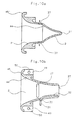
- the band guide 2 is shown in perspective.
- the area of the tape guide exit 27 is to get as close as possible to the clamping point 26 to beveled.
- FIG. 8a essentially corresponds to FIG. 6b.
- the Cover 43 can be folded down in this construction executed, d. H. stored in a swivel 39, so that, as shown in Fig. 8b, for cleaning the Belt guide 2 can be opened.
- FIG. 9a and 9b show two-stage forms of the Belt guide 2, a belt guide according to FIG. 9a 2 'connected to the tape guide 2 via connector 25 is. It is thereby possible to remove the tape guide 2 'from the Loosen tape guide 2 and if necessary in the area of Vent opening 37 accumulating fiber residues - snow - or to remove impurities. This one too Construction enter the sliver 3 over the tape guide input 45 'into the tape guide 2' these pass through the tape guide exit 27 ' the tape guide input 45 and leave the Tape guide 2 through the tape guide exit 27.
- the construction of the construction acc. 9b is analog. However, in this case the band guide 2 ' and the tape guide 2 is an integral part.
- the air outlet openings 37 are laterally and as in FIG. 9a arranged in the top surface 43 of the sliver guide 2 '.
- FIG. 10a and 10b are further exemplary embodiments.
- the construction acc. Fig. 10a again is carried out in two stages and in the area of the tape guide exit 27 ', i.e. at the end of the tape guide 2', Vent openings 37 are present.
- the band guide 2 is longer as such designed, the side walls less against each other are inclined.
- ventilation openings 37 both in the bottom 42 and in the Cover surface 43 arranged.
- The is in the inlet area Band guide 2 provided with flanges 49, the holes Have 50 for attachment to the machine frame.
- 11a and 11b differ from the 9 and 10 in that the side walls are not curved, but are just executed.
- Fig. 11b is the section through Fig. 11a acc. the line aa.
- the constriction 23 shows the measurement takes place, parallel walls 35.
- the feeler element 22 presses with its sliding surface 34 on the not shown Fiber strands 3 so that these against the counter surface 41 are pressed.
- the band guide 2 is a Squeeze rollers pair 46, 47 upstream, that is the task has the slivers 3 from the delivered Pull drums and thereby the take-off rollers 4, 5 to relieve. Between the two pairs of rollers there is practically no delay.
- the take-off rollers 4, 5 only need the compression the sliver 3 applied frictional resistance between sliver 3 and sliver guide 2 with overcome the probe element 22 arranged therein, the force exerted on the slivers 3 can thereby be less so that a tear off one or several slivers 3 is avoided.
- FIG. 13 shows a similar design variant like Fig. 12, but in this case there are two tape guides 2, 2 'present, between which the pair of squeeze rollers 46, 47 is inserted. The has also been changed Position of the take-off rollers 4, 5, which in this case are vertical are arranged.
- this is now Dimension D reduced, d. H. the slivers 3 are over the width, in this case compacted from above.
- the key element is designed so that it except the scanning movement, i.e. the compression movement in the direction of the slivers 3, also one Can perform pivoting movement and takes into account that fiber strips 3 of different strength, if necessary, side by side are arranged.
Claims (77)
- Dispositif pour mesurer l'épaisseur d'un ruban composite de fibres, comportant un guidage de ruban (2) pour guider les rubans de fibres (3) à l'entrée du banc d'étirage, dont les parois sont au moins partiellement coniques et réalisées de manière à réunir dans un plan les rubans de fibres rentrants, et en aval duquel est agencée une paire de cylindres (4, 5) après lesquels les rubans de fibres (3) divergent à nouveau, dans lequel est prévu un élément palpeur (22) chargé mobile qui forme conjointement avec une contre-surface fixe un étranglement pour le composite de fibres passant constitué en rubans de fibres et dont le changement de position agit, lorsque le ruban de fibres présente différentes épaisseurs, sur un dispositif convertisseur pour produire une impulsion de commande, caractérisé en ce que l'élément palpeur (22) est associé au guidage de ruban (2), en ce que le composite de fibres constitué de ruban de fibres (3) peut être comprimé et palpé dans un plan par l'élément palpeur (22) dans le guidage de ruban (2), et en ce que le composite de fibres palpé constitué de rubans de fibres (3) peut être tiré à par la paire de cylindres (4, 5).
- Dispositif selon la revendication 1, caractérisé en ce que l'élément palpeur mobile (22) est associé au guidage de ruban (2) dans la région des rubans de fibres (3) réunis les uns à côté des autres dans l'étranglement (23), et présente une surface de coulissement (34) qui presse les rubans de fibres (3) les uns à côté des autres en les comprimant contre la contre-surface fixe (41) du guidage de ruban (2), et en ce que la paire de cylindres (4, 5) tire les rubans de fibres (3) les uns à côté des autres, qui sont comprimés et palpés dans l'étranglement.
- Dispositif selon l'une ou l'autre des revendications 1 et 2, caractérisé en ce que la distance (a) entre l'élément palpeur mobile (22) et le point de serrage (26) de la paire des cylindres (4, 5) est égale ou inférieure à la longueur d'empilement du matériau de fibres.
- Dispositif selon l'une quelconque des revendications 1 à 3, caractérisé en ce que la distance (b) entre la sortie (27) du guidage de ruban (2) et le point de serrage (26) de la paire des cylindres (4, 5) est égale ou inférieure à la longueur d'empilement du matériau de fibres.
- Dispositif selon l'une quelconque des revendications 1 à 4, caractérisé en ce que l'élément palpeur (22) est mobile horizontalement et perpendiculairement par rapport à la direction de circulation du ruban.
- Dispositif selon l'une quelconque des revendications 1 à 5, caractérisé en ce que l'élément palpeur (22) est mobile verticalement et perpendiculairement par rapport à la direction de circulation de ruban.
- Dispositif selon l'une quelconque des revendications 1 à 6, caractérisé en ce que le guidage de ruban (2) présente au moins une ouverture (28), et l'élément palpeur (22) s'engage à travers l'ouverture (28).
- Dispositif selon l'une quelconque des revendications 1 à 7, caractérisé en ce que la sortie (27) du guidage de ruban (2) se trouve directement en avant de la fente (29) des cylindres de tirage (4, 5).
- Dispositif selon l'une quelconque des revendications 1 à 8, caractérisé en ce que l'étranglement (23) est agencé directement en avant de la sortie (27) du guidage de ruban (2).
- Dispositif selon l'une quelconque des revendications 1 à 9, caractérisé en ce que la force de tirage est supérieure à la force de mesure.
- Dispositif selon l'une quelconque des revendications 1 à 10, caractérisé en ce que l'ouverture (28) est un évidement (28').
- Dispositif selon l'une quelconque des revendications 1 à 7, caractérisé en ce que l'évidement (28') est approximativement rectangulaire.
- Dispositif selon l'une quelconque des revendications 1 à 12, caractérisé en ce que l'élément palpeur (22) est un élément palpeur approximativement rectangulaire, dont les grands côtés s'étendent dans la direction de la largeur et dont les petits côtés s'étendent dans la direction de travail.
- Dispositif selon l'une quelconque des revendications 1 à 13, caractérisé en ce que l'extrémité extérieure de l'élément palpeur (22) est agencée à une faible distance de la sortie (27) du guidage de ruban (2) en direction des cylindres de tirage (4, 5).
- Dispositif selon l'une quelconque des revendications 1 à 14, caractérisé en ce que l'élément palpeur (22) est monté sur un pivot fixe (30).
- Dispositif selon l'une quelconque des revendications 1 à 15, caractérisé en ce qu'un levier (31) du montage pivotant (30) coopère avec un élément de force, par exemple un contrepoids, un ressort, ou similaire.
- Dispositif selon l'une quelconque des revendications 1 à 16, caractérisé en ce que l'élément palpeur (22) est monté de façon mobile en direction horizontale.
- Dispositif selon l'une quelconque des revendications 1 à 17, caractérisé en ce que l'élément palpeur (22) est monté par l'une de ses extrémités avec effet à ressort.
- Dispositif selon l'une quelconque des revendications 1 à 18, caractérisé en ce que l'élément palpeur (22) est monté sur un organe de retenue, par exemple un levier.
- Dispositif selon l'une quelconque des revendications 1 à 19, caractérisé en ce que l'élément palpeur (22) est monté en rotation autour d'un axe vertical.
- Dispositif selon l'une quelconque des revendications 1 à 20, caractérisé en ce que l'élément palpeur (22) présente au moins un élément de mesure inductif (48) comportant un noyau plongeur et une bobine mobile.
- Dispositif selon l'une quelconque des revendications 1 à 21, caractérisé en ce que l'élément de mesure est un détecteur de distance sans contact à fonctionnement analogique, par exemple un déclencheur de proximité inductif.
- Dispositif selon l'une quelconque des revendications 1 à 22, caractérisé en ce qu'à l'élément palpeur (22) est associée une butée (33).
- Dispositif selon l'une quelconque des revendications 1 à 23, caractérisé en ce que l'élément palpeur (22) est chargé et supporté par au moins une force.
- Dispositif selon l'une quelconque des revendications 1 à 24, caractérisé en ce que l'étranglement (23) est réalisé à la manière d'un diaphragme d'appareil photographique, donc comme une fermeture à diaphragme comportant des surfaces de coulissement intérieures.
- Dispositif selon l'une quelconque des revendications 1 à 25, caractérisé en ce que l'élément palpeur (22) monté de façon mobile traverse une traversée correspondante de la paroi du guidage de ruban (2) et charge par une surface de coulissement (34) le ruban composite de fibres respectif jusqu'à proximité de la section transversale de la substance.
- Dispositif selon l'une quelconque des revendications 1 à 26, caractérisé en ce que l'étranglement (23) présente deux surfaces (35) parallèles l'une à l'autre, entre lesquelles est ajustée une partie de l'élément palpeur (22) monté de façon mobile.
- Dispositif selon l'une quelconque des revendications 1 à 27, caractérisé en ce que la paroi (41) située en vis-à-vis de l'élément palpeur (22) monté de façon mobile s'étend perpendiculairement aux surfaces parallèles (35).
- Dispositif selon l'une quelconque des revendications 1 à 28, caractérisé en ce que la précontrainte de l'élément palpeur (22) monté de façon mobile s'effectue par des moyens mécaniques, électriques, hydrauliques ou pneumatiques, par exemple des ressorts, des poids, par auto-élasticité, par des cylindres de charge, des aimants ou similaires, et en ce qu'elle peut être réglable.
- Dispositif selon l'une quelconque des revendications 1 à 29, caractérisé en ce que l'élément palpeur (22) monté de façon mobile est réalisé sous forme d'un levier coudé qui est monté approximativement au point de pliage dans l'évidement (28) du guidage de ruban (2), et soit le levier coudé soit le guidage de ruban (2) est monté de manière fixe et le levier coudé est chargé par un ressort.
- Dispositif selon l'une quelconque des revendications 1 à 30, caractérisé en ce que le ressort (32) chargeant le levier coudé (31) s'appuie par son extrémité libre contre un élément de butée (36) à réglage fin.
- Dispositif selon l'une quelconque des revendications 1 à 31, caractérisé en ce que les axes des cylindres de tirage (4, 5) sont agencés horizontalement.
- Dispositif selon l'une quelconque des revendications 1 à 32, caractérisé en ce que les axes des cylindres de tirage (4, 5) sont agencés verticalement.
- Dispositif selon l'une quelconque des revendications 1 à 33, caractérisé en ce qu'en amont du guidage de ruban (2) est agencé un autre guidage de ruban (2'), la région entre les deux guidages de ruban (2, 2') étant en liaison avec l'air ambiant via au moins une ouverture (37).
- Dispositif selon l'une quelconque des revendications 1 à 34, caractérisé en ce que le guidage de ruban (2) présente au moins une ouverture de mise à l'air (37).
- Dispositif selon l'une quelconque des revendications 1 à 35, caractérisé en ce que l'entrée (45) du guidage de ruban (2) présente une section transversale rectangulaire.
- Dispositif selon l'une quelconque des revendications 1 à 36, caractérisé en ce que la sortie (27) du guidage de ruban (2) présente une section transversale rectangulaire.
- Dispositif selon l'une quelconque des revendications 1 à 37, caractérisé en ce que la sortie (27) du guidage de ruban (2) s'étend jusqu'à la fente (29) entre les cylindres de tirage (4, 5).
- Dispositif selon l'une quelconque des revendications 1 à 38, caractérisé en ce que les parois latérales (40, 41, 42, 43) du guidage de ruban (2) sont réalisées de manière à converger coniquement dans la direction de circulation du ruban.
- Dispositif selon l'une quelconque des revendications 1 à 39, caractérisé en ce que la paroi de fond (42) et la paroi de plafond (43) du guidage de ruban (2) sont réalisées de manière à converger coniquement dans la direction de circulation du ruban.
- Dispositif selon l'une quelconque des revendications 1 à 40, caractérisé en ce que l'élément de paroi fixe (41) situé en vis-à-vis de l'élément palpeur (22) est variable en position, par exemple par une vis de réglage (38).
- Dispositif selon l'une quelconque des revendications 1 à 41, caractérisé en ce que l'élément palpeur (22) est réalisé en forme de trapèze.
- Dispositif selon l'une quelconque des revendications 1 à 42, caractérisé en ce que la surface de coulissement (34) de l'élément palpeur (22) est incurvée ou arrondie de façon convexe.
- Dispositif selon l'une quelconque des revendications 1 à 43, caractérisé en ce que la surface intérieure de la paroi latérale du guidage de ruban (2) et l'élément palpeur (22) vont en se transformant l'un en l'autre en affleurement mutuel.
- Dispositif selon l'une quelconque des revendications 1 à 44, caractérisé en ce qu'à partir de l'épaisseur individuelle des rubans de fibres (3) est formée une valeur moyenne.
- Dispositif selon l'une quelconque des revendications 1 à 45, caractérisé en ce que la contre-surface fixe (41) est une surface de coulissement le long de laquelle glissent les rubans de fibres (3).
- Dispositif selon l'une quelconque des revendications 1 à 46, caractérisé en ce que la surface de coulissement (34) de l'élément palpeur (22) est réalisée de façon rectiligne en direction longitudinale.
- Dispositif selon l'une quelconque des revendications 1 à 47, caractérisé en ce qu'en amont du guidage de ruban (2) est agencée une paire de cylindres exprimeurs (46, 47).
- Dispositif selon l'une quelconque des revendications 1 à 48, caractérisé en ce qu'en aval du guidage de ruban (2) est agencée la première paire de cylindres d'étirage (10, 11) sous forme de cylindres de tirage.
- Dispositif selon l'une quelconque des revendications 1 à 49, caractérisé en ce que la vitesse d'amenée s'élève à environ 150 m/min.
- Dispositif selon l'une quelconque des revendications 1 à 50, caractérisé en ce que la force de tirage est supérieure à la force de serrage au niveau de l'étranglement (23).
- Dispositif selon l'une quelconque des revendications 1 à 51, caractérisé en ce que la force de serrage est inférieure à la force d'arrachement.
- Dispositif selon l'une quelconque des revendications 1 à 52, caractérisé en ce qu'au moins la surface de plafond (43) du guidage de ruban (2) peut être dépliée et refermée.
- Dispositif selon l'une quelconque des revendications 1 à 53, caractérisé en ce que la surface de plafond (43) est fixée sur une articulation tournante (39).
- Dispositif selon l'une quelconque des revendications 1 à 54, caractérisé en ce que la paire de cylindres (4, 5) est une paire de calandres cylindriques.
- Dispositif selon l'une quelconque des revendications I à 55, pour mesurer l'épaisseur d'un ruban composite de fibres, comportant un guidage de ruban pour guider les rubans de fibres à l'entrée du banc d'étirage, qui présente une surface de plafond et une surface de fond et dont les parois latérales sont coniques et réalisées de manière à réunir les rubans de fibres rentrants les uns à côté des autres dans un plan latéralement les uns à côté des autres, et en aval duquel est agencée une paire de cylindres après laquelle les rubans de fibres divergent à nouveau les uns à côté des autres, dans lequel est prévu un élément palpeur chargé mobile qui forme conjointement avec une contre-surface fixe un étranglement pour le composite de fibres passant constitué en rubans de fibres, et dont la modification en position agit, lors de différentes épaisseurs du ruban composite de fibres, sur un dispositif convertisseur pour produire une impulsion de commande, caractérisé en ce que l'élément palpeur mobile (22) du guidage de ruban (2) est associé dans la région des rubans de fibres (3) réunis les uns à côté des autres dans l'étranglement (23), et en ce qu'il présente une surface de coulissement (34) qui presse les rubans de fibres (3) les uns à côté des autres en les comprimant contre la contre-surface fixe (41) du guidage de ruban (2) et en ce que la paire de cylindres (4, 5) tire les rubans de fibres (3) les uns à côté des autres, qui sont comprimés et palpés dans l'étranglement.
- Dispositif selon l'une quelconque des revendications 1 à 56, caractérisé en ce que les arêtes du guidage de ruban (2) sont ébarbées.
- Dispositif selon l'une quelconque des revendications 1 à 57, caractérisé en ce que le guidage de ruban (2) est une pièce de fonderie.
- Dispositif selon l'une quelconque des revendications 1 à 58, caractérisé en ce que les surfaces de contact (44) du guidage de ruban (2), qui sont en contact avec le ruban de fibres (3) présentent un coefficient de friction faible.
- Dispositif selon l'une quelconque des revendications 1 à 59, caractérisé en ce que la surface de coulissement (34) de l'élément palpeur (6), qui est en contact avec le ruban de fibres (3) présente un coefficient de friction faible.
- Dispositif selon l'une quelconque des revendications 1 à 60, caractérisé en ce que le guidage de ruban (2) est émaillé au moins dans la région des surfaces de contact (44).
- Dispositif selon l'une quelconque des revendications 1 à 61, caractérisé en ce que la surface de coulissement (34) de l'élément palpeur (6) est émaillée.
- Dispositif selon l'une quelconque des revendications 1 à 62, caractérisé en ce que le guidage de ruban (2) est constitué en verre.
- Dispositif selon l'une quelconque des revendications 1 à 61, caractérisé en ce que le guidage de ruban (2) est constitué en céramique.
- Dispositif selon l'une quelconque des revendications 1 à 64, caractérisé en ce qu'au moins la surface de coulissement (34) de l'élément palpeur (6) est constituée en verre.
- Dispositif selon l'une quelconque des revendications 1 à 65, caractérisé en ce qu'au moins la surface de coulissement (34) de l'élément palpeur (6) est constituée en céramique.
- Dispositif selon l'une quelconque des revendications 1 à 66, caractérisé en ce que la céramique est une céramique frittée.
- Dispositif selon l'une quelconque des revendications 1 à 67, caractérisé en ce que la céramique est une céramique d'oxyde.
- Dispositif selon l'une quelconque des revendications 1 à 62, caractérisé en ce que le guidage de ruban (2) est constitué en métal ou en un alliage métallique.
- Dispositif selon l'une quelconque des revendications 1 à 69, caractérisé en ce que les surfaces de contact (44) sont polies.
- Dispositif selon l'une quelconque des revendications 1 à 70, caractérisé en ce que les surfaces de contact (44) sont durcies.
- Dispositif selon l'une quelconque des revendications 1 à 71, caractérisé en ce que les surfaces de contact (44) sont constituées par des inserts en substance dure.
- Dispositif selon l'une quelconque des revendications 1 à 72, caractérisé en ce que le guidage de ruban (2) présente dans l'étranglement (23) une section transversale sensiblement rectangulaire.
- Dispositif selon l'une quelconque des revendications 1 à 73, caractérisé en ce que la section transversale va en se rétrécissant en direction de l'élément palpeur (6).
- Dispositif selon l'une quelconque des revendications 1 à 74, caractérisé en ce qu'au moins l'une des parois (40, 41, 42, 43) délimitant la section transversale est inclinée vers la paroi située à l'opposé pour le rétrécissement en section.
- Dispositif selon l'une quelconque des revendications 1 à 75, caractérisé en ce que le guidage de ruban (2) présente sensiblement la forme d'un tronc de pyramide.
- Dispositif selon l'une quelconque des revendications 1 à 76, caractérisé en ce que l'élément palpeur (6) traverse un petit côté (40, 41) du guidage de ruban (2).
Applications Claiming Priority (4)
| Application Number | Priority Date | Filing Date | Title |
|---|---|---|---|
| DE4310820 | 1993-04-02 | ||
| DE4310820 | 1993-04-02 | ||
| DE4404326 | 1994-02-11 | ||
| DE4404326A DE4404326A1 (de) | 1993-04-02 | 1994-02-11 | Vorrichtung zur Messung der Stärke eines Faserbandes mit einer Bandführung zum Führen der Faserbänder am Streckwerkseinlauf |
Publications (3)
| Publication Number | Publication Date |
|---|---|
| EP0626472A1 EP0626472A1 (fr) | 1994-11-30 |
| EP0626472B1 EP0626472B1 (fr) | 1997-05-28 |
| EP0626472B2 true EP0626472B2 (fr) | 1999-12-29 |
Family
ID=25924599
Family Applications (1)
| Application Number | Title | Priority Date | Filing Date |
|---|---|---|---|
| EP94104052A Expired - Lifetime EP0626472B2 (fr) | 1993-04-02 | 1994-03-16 | Dispositif pour mesurer l'épaisseur d'une matière fibreuse avec un guide-mèche pour guider la mèche à l'entrée du système d'étirage |
Country Status (9)
| Country | Link |
|---|---|
| US (1) | US5461757A (fr) |
| EP (1) | EP0626472B2 (fr) |
| JP (1) | JP3459459B2 (fr) |
| BR (1) | BR9401327A (fr) |
| CH (1) | CH691600A5 (fr) |
| DE (2) | DE4404326A1 (fr) |
| FR (1) | FR2703446B1 (fr) |
| GB (1) | GB2277106B (fr) |
| IT (1) | IT1273411B (fr) |
Families Citing this family (48)
| Publication number | Priority date | Publication date | Assignee | Title |
|---|---|---|---|---|
| DE4438882A1 (de) * | 1994-10-31 | 1996-05-02 | Truetzschler Gmbh & Co Kg | Vorrichtung zur Messung der Stärke eines Faserverbandes an einer Strecke z. B. Regulierstrecke |
| DE4438883A1 (de) * | 1994-10-31 | 1996-05-02 | Truetzschler Gmbh & Co Kg | Vorrichtung zur Messung der Stärke eines Faserverbandes an einer Strecke, insbesondere einer regulierenden Strecke |
| DE4438885B4 (de) * | 1994-10-31 | 2004-08-26 | Trützschler GmbH & Co KG | Vorrichtung zur Messung der Stärke eines Faserverbandes an einer regulierenden Strecke |
| GB2295163B (en) * | 1994-10-31 | 1998-07-29 | Truetzschler Gmbh & Co Kg | Apparatus and method for guiding a fibre sliver combination at a draw frame |
| DE4438884B4 (de) * | 1994-10-31 | 2004-08-26 | Trützschler GmbH & Co KG | Vorrichtung zur Messung der Stärke eines Faserverbandes an einer Regulierstrecke |
| DE19528484A1 (de) * | 1995-08-03 | 1997-02-06 | Truetzschler Gmbh & Co Kg | Vorrichtung an einer Strecke zur Messung der Stärke eines Faserverbandes |
| DE19500189B4 (de) * | 1995-01-05 | 2006-09-14 | Rieter Ingolstadt Spinnereimaschinenbau Ag | Verfahren zur Anpressung eines Tastorgans an einen Faserverband in einer Bandführung und Vorrichtung zu deren Erzeugung |
| DE19548232C5 (de) * | 1995-03-11 | 2013-08-14 | Trützschler GmbH & Co Kommanditgesellschaft | Verfahren und Vorrichtung zum Trennen eines Faserbandes beim Kannenwechsel an einer Strecke |
| JPH0913237A (ja) * | 1995-06-29 | 1997-01-14 | Zellweger Luwa Ag | スライバの太さ又はムラを求めるための装置 |
| US5796635A (en) * | 1995-08-08 | 1998-08-18 | Rieter Ingolstadt Spinnereimaschinenbau Ag | Device and process for linear measurement of fiber sliver thickness or mass |
| DE19537470A1 (de) * | 1995-10-07 | 1997-05-07 | Stahlecker Fritz | Streckwerk für Spinnereimaschinen |
| DE19537983A1 (de) * | 1995-10-12 | 1997-04-17 | Truetzschler Gmbh & Co Kg | Vorrichtung an einer Spinnereivorbereitungsmaschine, insbesondere einer Strecke, zum Messen der Stärke eines Faserbandes |
| DE19537982A1 (de) * | 1995-10-12 | 1997-04-17 | Truetzschler Gmbh & Co Kg | Vorrichtung an einer Spinnereivorbereitungsmaschine, insbesondere einer Strecke, zum Messen der Stärke eines Faserverbandes |
| GB2315498B (en) * | 1996-06-29 | 2001-01-24 | Truetzschler Gmbh & Co Kg | Apparatus and method for forming a fibre web into a fibre sliver |
| DE19721758B4 (de) * | 1996-06-29 | 2010-12-02 | TRüTZSCHLER GMBH & CO. KG | Vorrichtung an einer Karde, bei der am Ausgang der Karde ein Flortrichter mit Abzugswalzen vorhanden ist |
| IT1292144B1 (it) * | 1996-06-29 | 1999-01-25 | Truetzschler & Co | Dispositivo su una carda,in cui all'uscita della carda e' previsto un imbuto del velo con cilindri di estrazione |
| US6581248B1 (en) * | 1997-01-23 | 2003-06-24 | Maschinenfabrik Rieter Ag | Carding machine with drawing rollers at the outlet |
| DE19822886B4 (de) * | 1997-07-01 | 2007-03-29 | TRüTZSCHLER GMBH & CO. KG | Regulierstreckwerk für einen Faserverband, z. B. Baumwolle, Chemiefasern o. dgl. mit mindestens einem Verzugsfeld |
| WO1999011847A1 (fr) * | 1997-09-01 | 1999-03-11 | Maschinenfabrik Rieter Ag | Banc d'etirage regule |
| US6119312A (en) * | 1997-09-08 | 2000-09-19 | Trutzschler Gmbh & Co. Kg | Device mounted on a spinning preparation machine, such as carding machine, a draw frame or the like, for guiding and compressing a sliver bundle |
| DE19739186A1 (de) * | 1997-09-08 | 1999-03-11 | Truetzschler Gmbh & Co Kg | Vorrichtung zum Verbinden und Zuführen von Faserbändern, insbesondere Karden- oder Streckenbändern |
| IT1302166B1 (it) * | 1997-09-17 | 2000-07-31 | Truetzschler & Co | Dispositivo su uno striratoio per la misura di una nastro di fibrecomposito formato da nastri di fibre |
| DE19809875B4 (de) | 1998-03-07 | 2014-01-02 | Trützschler GmbH & Co Kommanditgesellschaft | Vorrichtung zum Zuführen von Faserbändern an Streckwerken von Spinnereimaschinen, insbesondere von Strecken |
| CH693181A5 (de) * | 1998-04-16 | 2003-03-27 | Truetzschler Gmbh & Co Kg | Vorrichtung am Ausgang einer Strecke. |
| DE19906139B4 (de) | 1999-02-13 | 2008-01-10 | TRüTZSCHLER GMBH & CO. KG | Regulierstreckwerk für einen Faserverband, z. B. Baumwolle, Chemiefasern o. dgl., mit mindestens einem Verzugsfeld |
| DE19908371A1 (de) * | 1999-02-26 | 2000-08-31 | Truetzschler Gmbh & Co Kg | Vorrichtung an einer Strecke zur Verarbeitung eines Faserverbandes aus Faserbändern |
| DE19908309B4 (de) * | 1999-02-26 | 2010-03-04 | Rieter Ingolstadt Gmbh | Vorrichtung zum Zuführen eines Faserbandes zu einem Streckwerk einer Strecke |
| ITMI20010079A1 (it) * | 2000-01-29 | 2002-07-17 | Truetzschler & Co | Dispositivo su una carda per ottenere un insieme di fibre |
| US6550106B2 (en) * | 2000-01-29 | 2003-04-22 | TRüTZSCHLER GMBH & CO. KG | Fiber web guiding device for forming a sliver from a fiber web |
| DE10145733B4 (de) * | 2000-10-19 | 2017-02-16 | Trützschler GmbH & Co Kommanditgesellschaft | Vorrichtung an einer Karde oder Krempel zur Bildung eines Faserverbandes |
| DE10041894B4 (de) | 2000-08-25 | 2011-08-11 | Trützschler GmbH & Co. KG, 41199 | Verfahren und Vorrichtung zum Verstrecken von Faserband in einer Regulierstrecke für Fasermaterial zum direkten Ermitteln von Einstellwerten für den Reguliereinsatzpunkt |
| DE10041893A1 (de) * | 2000-08-25 | 2002-03-07 | Truetzschler Gmbh & Co Kg | Vorrichtung an einer Regulierstrecke zum direkten Ermitteln von Einstellwerten für den Reguliereinsatzpunkt |
| DE10041892A1 (de) | 2000-08-25 | 2002-03-07 | Truetzschler Gmbh & Co Kg | Vorrichtung an einer Regulierstrecke für Faserbänder zum direkten Ermitteln von Einstellwerten für den Reguliereinsatzpunkt |
| DE10057699A1 (de) * | 2000-11-21 | 2002-05-23 | Truetzschler Gmbh & Co Kg | Vorrichtung an einer Strecke zur Verarbeitung von Faserbändern, z. B. Baumwolle, Chemiefasern u. dgl. |
| US6543092B2 (en) | 2001-02-16 | 2003-04-08 | TRüTZSCHLER GMBH & CO. KG | Method of determining setting values for a preliminary draft in a regulated draw frame |
| DE10162312B4 (de) * | 2001-02-16 | 2011-06-09 | TRüTZSCHLER GMBH & CO. KG | Vorrichtung an einer Regulierstrecke für Faserbänder zum Ermitteln von Einstellwerten für den Vorverzug |
| CN100451195C (zh) * | 2001-12-19 | 2009-01-14 | 特鲁菲舍尔股份有限公司及两合公司 | 测定前端扭曲的调整值的装置 |
| DE10330767A1 (de) * | 2003-07-07 | 2005-02-10 | Rieter Ingolstadt Spinnereimaschinenbau Ag | Fadenberührendes Bauteil von Spinnmaschinen |
| JP2007505226A (ja) * | 2003-09-12 | 2007-03-08 | マシーネンファブリク リーター アクチェンゲゼルシャフト | 空気精紡法によって粗紡糸を製造するための練条機・粗紡機組み合わせ体 |
| CN1882728B (zh) * | 2003-09-12 | 2010-09-01 | 里特机械公司 | 并条-头道粗纱联合机和用于从纤维组中制造粗纱的方法 |
| DE102004028358A1 (de) * | 2004-06-11 | 2005-12-29 | Trützschler GmbH & Co KG | Vorrichtung für eine bandbildende Textilmaschine, insbesondere Strecke, Karde o. dgl., mit einer Vliesführung |
| CZ20041131A3 (cs) * | 2004-11-19 | 2006-07-12 | Výzkumný ústav textilních stroju Liberec a. s. | Zpusob merení délkových nestejnomerností pramenu textilních vláken a podobných délkových útvaru a zarízení k jeho provádení |
| DE102005023992A1 (de) | 2005-05-20 | 2006-11-23 | TRüTZSCHLER GMBH & CO. KG | Vorrichtung an einer Spinnereivorbereitungsmaschine, z.B. Karde, Krempel, Strecke, Kämmmaschine o.dgl., zum Ermitteln der Masse und/oder Masseschwankungen eines Fasermaterials, z.B. mindestens ein Faserband, Faservlies o.dgl., aus Baumwolle, Chemiefasern o. dgl. |
| DE102005033180B4 (de) | 2005-07-13 | 2020-03-12 | Trützschler GmbH & Co Kommanditgesellschaft | Vorrichtung zum Erfassen eines Parameters an mehreren, einem Streckwerk einer Spinnereimaschine zugeführten Faserbändern |
| EP2006659A1 (fr) * | 2007-06-19 | 2008-12-24 | Dalphi Metal Espana, S.A. | Procédé et appareil pour la mesure de l'élasticité de matériaux de revêtement de composants pour véhicule |
| CH701226A1 (de) * | 2009-06-04 | 2010-12-15 | Uster Technologies Ag | Vorrichtung und verfahren zur messung der masse eines bewegten faserbandes. |
| CN105088450A (zh) * | 2015-07-16 | 2015-11-25 | 青岛腾威纺控科技有限公司 | 一种并条机数字匀整控制系统 |
| GB2601290B (en) * | 2020-10-07 | 2023-11-29 | Aquatec Group Ltd | Strain monitor |
Citations (3)
| Publication number | Priority date | Publication date | Assignee | Title |
|---|---|---|---|---|
| CH635373A5 (de) † | 1979-04-06 | 1983-03-31 | Zellweger Uster Ag | Mess- und regeleinrichtung mit einem messtrichter zur bestimmung der durchzugskraft von faserbaendern. |
| CH668833A5 (de) † | 1986-01-16 | 1989-01-31 | Zellweger Uster Ag | Vorrichtung zum messen und/oder vergleichmaessigen der banddicke von faserbaendern. |
| EP0460442A1 (fr) † | 1990-05-30 | 1991-12-11 | Zellweger Luwa Ag | Dispositif de mesure de l'épaisseur et/ou de l'inégalite de rubans de fibres |
Family Cites Families (12)
| Publication number | Priority date | Publication date | Assignee | Title |
|---|---|---|---|---|
| GB1135752A (en) * | 1966-11-03 | 1968-12-04 | Tmm Research Ltd | Improvements in or relating to textile drafting systems |
| US3822590A (en) * | 1972-05-01 | 1974-07-09 | Maremont Corp | Textile sliver unevenness detecting |
| CH553981A (de) * | 1972-05-10 | 1974-09-13 | Rieter Ag Maschf | Vorrichtung zur messung von dichteschwankungen eines faserbandes in spinnereimaschinen. |
| US4267620A (en) * | 1978-08-17 | 1981-05-19 | Special Instruments Laboratory, Inc. | Method and apparatus for controlling textile working systems employing NMR detector |
| US4266324A (en) * | 1978-12-27 | 1981-05-12 | Kabushiki Kaisha Toyota Chuo Kenkyusho | Silver weight unevenness correcting apparatus |
| DE3616196A1 (de) * | 1986-05-14 | 1987-11-19 | Seydel Spinnereimasch | Verfahren und vorrichtung zum verflechten von faserbaendern |
| DE3807582A1 (de) * | 1988-03-08 | 1989-09-21 | Hollingsworth Gmbh | Vorrichtung zum komprimieren und selbsttaetigen einfuehren eines textilen faserbandes |
| DE3834110A1 (de) * | 1988-10-07 | 1990-04-12 | Truetzschler & Co | Verfahren und vorrichtung zur bewegungserfassung von textilfaserbaendern, z. b. kardenbaendern |
| DE3913548C2 (de) * | 1989-04-25 | 2000-08-31 | Truetzschler Gmbh & Co Kg | Vorrichtung zum Messen der Banddicke und der Ungleichmäßigkeit eines Faserbandes an Spinnereivorbereitungsmaschinen |
| DE4017064A1 (de) * | 1989-08-07 | 1991-02-14 | Truetzschler & Co | Verfahren und vorrichtung zum automatischen anspinnen eines faserflors zu einem faserband, z. b. bei einer karde |
| DE4012551C1 (fr) * | 1990-04-19 | 1991-06-27 | Schubert & Salzer Maschinenfabrik Ag, 8070 Ingolstadt, De | |
| DE4142038C5 (de) * | 1991-12-19 | 2012-03-15 | Rieter Ingolstadt Gmbh | Vorrichtung zur Verarbeitung einer Mehrzahl von Faserbändern |
-
1994
- 1994-02-11 DE DE4404326A patent/DE4404326A1/de not_active Withdrawn
- 1994-03-16 DE DE59402882T patent/DE59402882D1/de not_active Expired - Fee Related
- 1994-03-16 EP EP94104052A patent/EP0626472B2/fr not_active Expired - Lifetime
- 1994-03-29 BR BR9401327A patent/BR9401327A/pt not_active IP Right Cessation
- 1994-03-31 GB GB9406446A patent/GB2277106B/en not_active Expired - Fee Related
- 1994-03-31 CH CH00978/94A patent/CH691600A5/de not_active IP Right Cessation
- 1994-04-01 IT ITMI940635A patent/IT1273411B/it active IP Right Grant
- 1994-04-01 FR FR9403889A patent/FR2703446B1/fr not_active Expired - Fee Related
- 1994-04-01 JP JP06480794A patent/JP3459459B2/ja not_active Expired - Fee Related
- 1994-04-04 US US08/222,792 patent/US5461757A/en not_active Expired - Lifetime
Patent Citations (3)
| Publication number | Priority date | Publication date | Assignee | Title |
|---|---|---|---|---|
| CH635373A5 (de) † | 1979-04-06 | 1983-03-31 | Zellweger Uster Ag | Mess- und regeleinrichtung mit einem messtrichter zur bestimmung der durchzugskraft von faserbaendern. |
| CH668833A5 (de) † | 1986-01-16 | 1989-01-31 | Zellweger Uster Ag | Vorrichtung zum messen und/oder vergleichmaessigen der banddicke von faserbaendern. |
| EP0460442A1 (fr) † | 1990-05-30 | 1991-12-11 | Zellweger Luwa Ag | Dispositif de mesure de l'épaisseur et/ou de l'inégalite de rubans de fibres |
Also Published As
| Publication number | Publication date |
|---|---|
| IT1273411B (it) | 1997-07-08 |
| ITMI940635A0 (it) | 1994-04-01 |
| EP0626472A1 (fr) | 1994-11-30 |
| BR9401327A (pt) | 1994-10-25 |
| US5461757A (en) | 1995-10-31 |
| DE4404326A1 (de) | 1994-10-06 |
| EP0626472B1 (fr) | 1997-05-28 |
| CH691600A5 (de) | 2001-08-31 |
| GB2277106B (en) | 1997-08-27 |
| JPH06306713A (ja) | 1994-11-01 |
| FR2703446A1 (fr) | 1994-10-07 |
| GB9406446D0 (en) | 1994-05-25 |
| ITMI940635A1 (it) | 1995-10-01 |
| GB2277106A (en) | 1994-10-19 |
| DE59402882D1 (de) | 1997-07-03 |
| FR2703446B1 (fr) | 1997-10-31 |
| JP3459459B2 (ja) | 2003-10-20 |
Similar Documents
| Publication | Publication Date | Title |
|---|---|---|
| EP0626472B2 (fr) | Dispositif pour mesurer l'épaisseur d'une matière fibreuse avec un guide-mèche pour guider la mèche à l'entrée du système d'étirage | |
| DE19528484A1 (de) | Vorrichtung an einer Strecke zur Messung der Stärke eines Faserverbandes | |
| CH699383A2 (de) | Vorrichtung für eine oder an einer Spinnereivorbereitungsmaschine, die ein Streckwerk zum Verstrecken von strangförmigem Fasermaterial aufweist. | |
| EP2390391A2 (fr) | Machine de préparation de filature | |
| CH694055A5 (de) | Vorrichtung an einer Strecke zur Verarbeitung eines Faserverbandes aus Faserbändern. | |
| DE19823805A1 (de) | Vorrichtung an einer Spinnereivorbereitungsmaschine, z. B. Karde, Strecke o. dgl., zum Führen und Verdichten eines Faserverbandes | |
| CH693775A5 (de) | Vorrichtung an einer Strecke zur Messung eines Faserverbandes aus Faserbaendern. | |
| DE10140645B4 (de) | Verfahren zum Betreiben eines Streckwerks sowie Streckwerk | |
| CH699382A2 (de) | Vorrichtung für eine oder an einer Spinnereivorbereitungsmaschine, die ein Streckwerk zum Verstrecken von strangförmigem Fasermaterial aufweist. | |
| DE10146907B4 (de) | Vlieszuführvorrichtung | |
| DE19950901A1 (de) | Vorrichtung zum Messen der Dicke und/oder der Ungleichmäßigkeit von Faserbändern | |
| DE4438883A1 (de) | Vorrichtung zur Messung der Stärke eines Faserverbandes an einer Strecke, insbesondere einer regulierenden Strecke | |
| DE4438885B4 (de) | Vorrichtung zur Messung der Stärke eines Faserverbandes an einer regulierenden Strecke | |
| CH693181A5 (de) | Vorrichtung am Ausgang einer Strecke. | |
| CH692987A5 (de) | Vorrichtung an einer Spinnereivorbereitungsmaschine, insbesondere Karde oder Strecke. | |
| EP0751243B1 (fr) | Dispositif pour mesurer l'épaisseur et/ou l'inégalité de rubans de fibres | |
| DE4438884B4 (de) | Vorrichtung zur Messung der Stärke eines Faserverbandes an einer Regulierstrecke | |
| DE19819728A1 (de) | Vorrichtung an einer Strecke zur Messung eines Faserverbandes aus Faserbändern | |
| DE19909040A1 (de) | Vorrichtung am Ausgang einer Strecke | |
| DE4438882A1 (de) | Vorrichtung zur Messung der Stärke eines Faserverbandes an einer Strecke z. B. Regulierstrecke | |
| EP0417614B1 (fr) | Appareil pour comprimer continuellement ou pour contrôler la masse d'un ruban de fibres | |
| EP1654407B1 (fr) | Dispositif de guidage de non-tisse pour machine textile et machine textile | |
| WO2006070008A1 (fr) | Procede pour determiner la masse lineique ou la section d'un composite fibreux textile et dispositif correspondant | |
| DE19823571A1 (de) | Vorrichtung an einer Spinnereivorbereitungsmaschine, insbesondere Karde, Strecke o. dgl., mit einem Faserführungsorgan | |
| EP3052681B1 (fr) | Étaleur-nappeur et procédé de fabrication d'une nappe à partir de rubans de fibres |
Legal Events
| Date | Code | Title | Description |
|---|---|---|---|
| PUAI | Public reference made under article 153(3) epc to a published international application that has entered the european phase |
Free format text: ORIGINAL CODE: 0009012 |
|
| AK | Designated contracting states |
Kind code of ref document: A1 Designated state(s): CH DE FR GB IT LI |
|
| 17P | Request for examination filed |
Effective date: 19950314 |
|
| 17Q | First examination report despatched |
Effective date: 19950413 |
|
| GRAG | Despatch of communication of intention to grant |
Free format text: ORIGINAL CODE: EPIDOS AGRA |
|
| GRAH | Despatch of communication of intention to grant a patent |
Free format text: ORIGINAL CODE: EPIDOS IGRA |
|
| GRAH | Despatch of communication of intention to grant a patent |
Free format text: ORIGINAL CODE: EPIDOS IGRA |
|
| GRAA | (expected) grant |
Free format text: ORIGINAL CODE: 0009210 |
|
| AK | Designated contracting states |
Kind code of ref document: B1 Designated state(s): CH DE FR GB IT LI |
|
| REG | Reference to a national code |
Ref country code: CH Ref legal event code: EP |
|
| REF | Corresponds to: |
Ref document number: 59402882 Country of ref document: DE Date of ref document: 19970703 |
|
| ET | Fr: translation filed | ||
| REG | Reference to a national code |
Ref country code: CH Ref legal event code: NV Representative=s name: A. BRAUN, BRAUN, HERITIER, ESCHMANN AG PATENTANWAE |
|
| GBT | Gb: translation of ep patent filed (gb section 77(6)(a)/1977) |
Effective date: 19970905 |
|
| PLBQ | Unpublished change to opponent data |
Free format text: ORIGINAL CODE: EPIDOS OPPO |
|
| PLBI | Opposition filed |
Free format text: ORIGINAL CODE: 0009260 |
|
| PLBF | Reply of patent proprietor to notice(s) of opposition |
Free format text: ORIGINAL CODE: EPIDOS OBSO |
|
| 26 | Opposition filed |
Opponent name: ZELLWEGER LUWA AG, USTER Effective date: 19980213 |
|
| PLBF | Reply of patent proprietor to notice(s) of opposition |
Free format text: ORIGINAL CODE: EPIDOS OBSO |
|
| PLAW | Interlocutory decision in opposition |
Free format text: ORIGINAL CODE: EPIDOS IDOP |
|
| PLAW | Interlocutory decision in opposition |
Free format text: ORIGINAL CODE: EPIDOS IDOP |
|
| PUAH | Patent maintained in amended form |
Free format text: ORIGINAL CODE: 0009272 |
|
| STAA | Information on the status of an ep patent application or granted ep patent |
Free format text: STATUS: PATENT MAINTAINED AS AMENDED |
|
| ITF | It: translation for a ep patent filed |
Owner name: BARZANO' E ZANARDO MILANO S.P.A. |
|
| 27A | Patent maintained in amended form |
Effective date: 19991229 |
|
| AK | Designated contracting states |
Kind code of ref document: B2 Designated state(s): CH DE FR GB IT LI |
|
| GBTA | Gb: translation of amended ep patent filed (gb section 77(6)(b)/1977) | ||
| REG | Reference to a national code |
Ref country code: CH Ref legal event code: AEN Free format text: AUFRECHTERHALTUNG DES PATENTES IN GEAENDERTER FORM |
|
| ET3 | Fr: translation filed ** decision concerning opposition | ||
| REG | Reference to a national code |
Ref country code: GB Ref legal event code: IF02 |
|
| PGFP | Annual fee paid to national office [announced via postgrant information from national office to epo] |
Ref country code: IT Payment date: 20080304 Year of fee payment: 15 Ref country code: GB Payment date: 20080312 Year of fee payment: 15 |
|
| REG | Reference to a national code |
Ref country code: CH Ref legal event code: PFA Owner name: TRUETZSCHLER GMBH & CO. KG Free format text: TRUETZSCHLER GMBH & CO. KG#DUVENSTRASSE 82-92#D-41199 MOENCHENGLADBACH (DE) -TRANSFER TO- TRUETZSCHLER GMBH & CO. KG#DUVENSTRASSE 82-92#D-41199 MOENCHENGLADBACH (DE) |
|
| PGFP | Annual fee paid to national office [announced via postgrant information from national office to epo] |
Ref country code: FR Payment date: 20080114 Year of fee payment: 15 Ref country code: DE Payment date: 20080306 Year of fee payment: 15 Ref country code: CH Payment date: 20080410 Year of fee payment: 15 |
|
| REG | Reference to a national code |
Ref country code: CH Ref legal event code: PL |
|
| GBPC | Gb: european patent ceased through non-payment of renewal fee |
Effective date: 20090316 |
|
| REG | Reference to a national code |
Ref country code: FR Ref legal event code: ST Effective date: 20091130 |
|
| PG25 | Lapsed in a contracting state [announced via postgrant information from national office to epo] |
Ref country code: LI Free format text: LAPSE BECAUSE OF NON-PAYMENT OF DUE FEES Effective date: 20090331 Ref country code: DE Free format text: LAPSE BECAUSE OF NON-PAYMENT OF DUE FEES Effective date: 20091001 Ref country code: CH Free format text: LAPSE BECAUSE OF NON-PAYMENT OF DUE FEES Effective date: 20090331 |
|
| PG25 | Lapsed in a contracting state [announced via postgrant information from national office to epo] |
Ref country code: GB Free format text: LAPSE BECAUSE OF NON-PAYMENT OF DUE FEES Effective date: 20090316 Ref country code: FR Free format text: LAPSE BECAUSE OF NON-PAYMENT OF DUE FEES Effective date: 20091123 |
|
| PG25 | Lapsed in a contracting state [announced via postgrant information from national office to epo] |
Ref country code: IT Free format text: LAPSE BECAUSE OF NON-PAYMENT OF DUE FEES Effective date: 20090316 |