EP0620164B1 - Verfahren zur Herstellung eines Verschlusses für eine Flasche oder dergleichen - Google Patents
Verfahren zur Herstellung eines Verschlusses für eine Flasche oder dergleichen Download PDFInfo
- Publication number
- EP0620164B1 EP0620164B1 EP94106369A EP94106369A EP0620164B1 EP 0620164 B1 EP0620164 B1 EP 0620164B1 EP 94106369 A EP94106369 A EP 94106369A EP 94106369 A EP94106369 A EP 94106369A EP 0620164 B1 EP0620164 B1 EP 0620164B1
- Authority
- EP
- European Patent Office
- Prior art keywords
- sealing
- face
- bottle neck
- sealing part
- cap
- Prior art date
- Legal status (The legal status is an assumption and is not a legal conclusion. Google has not performed a legal analysis and makes no representation as to the accuracy of the status listed.)
- Expired - Lifetime
Links
- 238000004519 manufacturing process Methods 0.000 title claims abstract description 6
- 238000007789 sealing Methods 0.000 claims abstract description 51
- 238000000034 method Methods 0.000 claims abstract description 8
- 239000000463 material Substances 0.000 claims abstract 4
- 229910052751 metal Inorganic materials 0.000 claims abstract 2
- 239000002184 metal Substances 0.000 claims abstract 2
- 230000008961 swelling Effects 0.000 claims 2
- 239000004411 aluminium Substances 0.000 claims 1
- 229910052782 aluminium Inorganic materials 0.000 claims 1
- XAGFODPZIPBFFR-UHFFFAOYSA-N aluminium Chemical compound [Al] XAGFODPZIPBFFR-UHFFFAOYSA-N 0.000 claims 1
- 238000003825 pressing Methods 0.000 abstract description 5
- 230000006835 compression Effects 0.000 description 5
- 238000007906 compression Methods 0.000 description 5
- 238000004880 explosion Methods 0.000 description 2
- 239000011324 bead Substances 0.000 description 1
- 235000013361 beverage Nutrition 0.000 description 1
- 150000001875 compounds Chemical class 0.000 description 1
- 238000010276 construction Methods 0.000 description 1
- 230000001419 dependent effect Effects 0.000 description 1
- 230000000694 effects Effects 0.000 description 1
- 239000006260 foam Substances 0.000 description 1
- 239000011521 glass Substances 0.000 description 1
- 239000012535 impurity Substances 0.000 description 1
- 239000007788 liquid Substances 0.000 description 1
- 238000004904 shortening Methods 0.000 description 1
- 230000007704 transition Effects 0.000 description 1
- 238000009423 ventilation Methods 0.000 description 1
Images


Classifications
-
- B—PERFORMING OPERATIONS; TRANSPORTING
- B21—MECHANICAL METAL-WORKING WITHOUT ESSENTIALLY REMOVING MATERIAL; PUNCHING METAL
- B21D—WORKING OR PROCESSING OF SHEET METAL OR METAL TUBES, RODS OR PROFILES WITHOUT ESSENTIALLY REMOVING MATERIAL; PUNCHING METAL
- B21D51/00—Making hollow objects
- B21D51/16—Making hollow objects characterised by the use of the objects
- B21D51/38—Making inlet or outlet arrangements of cans, tins, baths, bottles, or other vessels; Making can ends; Making closures
- B21D51/44—Making closures, e.g. caps
- B21D51/50—Making screw caps
-
- B—PERFORMING OPERATIONS; TRANSPORTING
- B65—CONVEYING; PACKING; STORING; HANDLING THIN OR FILAMENTARY MATERIAL
- B65D—CONTAINERS FOR STORAGE OR TRANSPORT OF ARTICLES OR MATERIALS, e.g. BAGS, BARRELS, BOTTLES, BOXES, CANS, CARTONS, CRATES, DRUMS, JARS, TANKS, HOPPERS, FORWARDING CONTAINERS; ACCESSORIES, CLOSURES, OR FITTINGS THEREFOR; PACKAGING ELEMENTS; PACKAGES
- B65D41/00—Caps, e.g. crown caps or crown seals, i.e. members having parts arranged for engagement with the external periphery of a neck or wall defining a pouring opening or discharge aperture; Protective cap-like covers for closure members, e.g. decorative covers of metal foil or paper
- B65D41/02—Caps or cap-like covers without lines of weakness, tearing strips, tags, or like opening or removal devices
- B65D41/04—Threaded or like caps or cap-like covers secured by rotation
- B65D41/0435—Threaded or like caps or cap-like covers secured by rotation with separate sealing elements
- B65D41/045—Discs
-
- B—PERFORMING OPERATIONS; TRANSPORTING
- B65—CONVEYING; PACKING; STORING; HANDLING THIN OR FILAMENTARY MATERIAL
- B65D—CONTAINERS FOR STORAGE OR TRANSPORT OF ARTICLES OR MATERIALS, e.g. BAGS, BARRELS, BOTTLES, BOXES, CANS, CARTONS, CRATES, DRUMS, JARS, TANKS, HOPPERS, FORWARDING CONTAINERS; ACCESSORIES, CLOSURES, OR FITTINGS THEREFOR; PACKAGING ELEMENTS; PACKAGES
- B65D51/00—Closures not otherwise provided for
- B65D51/16—Closures not otherwise provided for with means for venting air or gas
- B65D51/1633—Closures not otherwise provided for with means for venting air or gas whereby venting occurs by automatic opening of the closure, container or other element
- B65D51/1661—Closures not otherwise provided for with means for venting air or gas whereby venting occurs by automatic opening of the closure, container or other element by means of a passage for the escape of gas between the closure and the lip of the container mouth
Definitions
- the invention relates to a method for producing a closure of the type mentioned in the preamble of claim 1 for a bottle or the like.
- a closure in which, in addition to the radial sealing face on the front, axial sealing surfaces are provided in the region of the mouth edge of a bottle, into which the sealing compound of the seal extends.
- the sealing part is deep-drawn and extends around the mouth of the bottle so as to form the outer, axial sealing surface.
- the essence of this known closure should consist in the fact that the sealing part, at least in a partial area at the transition from the sealing part to the holding part, is not deep-drawn down to the lateral mouth edge of the neck of the bottle, but is rather excluded from such a deformation. In this way, a reduced sealing distance is to be created in the undeformed partial area, which, due to its brevity, should result in less tightness.
- a closure for a bottle or the like which has a cap-shaped holding part, on which there is an inward projection or collar for engaging behind an outer bead of a bottle neck.
- This holding part is connected via an elastic element to a sealing part with an annular sealing surface for contact with an end face of the bottle neck.
- the holding part has a stop for the defined contact of the holding part on the edge of the bottle neck. Since the sealing part also abuts the edge of the bottle neck, the mutual position of the holding part and the sealing part is precisely defined. Since the elastic element for prestressing the sealing part is located between the two, the size of the prestressing of the elastic element is also precisely defined and thus the pressure at which the sealing part lifts off, that is to say opens the pressure relief valve.
- a screw cap of the type mentioned in the preamble of claim 1 is known, in which between the bottom of the screw cap and the front edge of the bottle neck is a seal made of foam, which has different thicknesses in its cross section in a diametrical direction .
- the sealing force is therefore less in the areas of reduced thickness, and these areas are intended to serve as a pressure relief valve.
- the opening pressure depends on the compression of the entire seal and is therefore not independent of the screwing torque. If the screwing is done with too little torque, the areas of reduced thickness are not brought into contact, the seal is not tight.
- the inside of the bottle for example a beverage liquid
- the manufacturing tolerances or impurities on the end face of the bottle rim or on the seal make it impossible to seal the seal on the end face of the bottle neck.
- the invention is based on the object of specifying a method for the simple manufacture of a closure which is simple in construction and largely reliably opens at a predetermined excess pressure independently of the screw-on torque.
- the invention frees itself from the known idea of shortening the sealing distance or pressing the sealing part as a whole against the mouth of the bottle neck via an elastic element. Rather, the basic idea of the invention is to create a seal, stop and elastic element in one operation.
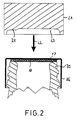
- a likewise flat sealing washer 18 is inserted into a cap-shaped closure, consisting of holding part 16 and sealing part 17, which is flat. Everything is then placed in the direction of an arrow 19 on the end of a bottle neck 20, as shown in FIG. 2.
- a stamp 21 is then in the direction of an arrow 22 pressed against the sealing part 17.
- the stamp 21 there is a recess 23, from which a projection 24 protrudes, which presses into the sealing part 17 when the stamp 21 is pressed on and produces recesses there at spaced apart locations, as can be seen from FIG. 3.
- a thread 27 as well as a collar 28 are produced by means not shown, by pressing from the outside onto the holding part 16, which serves to make the first opening of the bottle visible.
Landscapes
- Engineering & Computer Science (AREA)
- Mechanical Engineering (AREA)
- Closures For Containers (AREA)
- Containers Having Bodies Formed In One Piece (AREA)
- Glass Compositions (AREA)
- Filling Of Jars Or Cans And Processes For Cleaning And Sealing Jars (AREA)
- Closing Of Containers (AREA)
Description
- Die Erfindung betrifft ein Verfahren zur Herstellung eines Verschlusses der im Oberbegriff des Anspruchs 1 genannten Art für eine Flasche oder dergleichen.
- Durch DE 36 42 998 C1 ist ein Verschluß bekannt, bei dem zusätzlich zu der radialen, stirnseitigen Dichtfläche axiale Dichtflächen im Bereich des Mündungsrandes einer Flasche vorgesehen sind, in die sich Dichtmassse der Dichtung erstreckt. Das Dichtteil ist tiefgezogen und erstreckt sich um den Mündungsrand der Flasche herum, um so die äußere, axiale Dichtfläche zu bilden. Das Wesentliche dieses bekannten Verschlusses soll darin bestehen, daß das Dichtteil wenigstens in einem Teilbereich am Übergang von dem Dichtteil zu dem Halteteil nicht bis auf den seitlichen Mündungsrand des Halses der Flasche tiefgezogen ist, vielmehr von einer derartigen Verformung ausgenommen ist. Auf diese Weise soll in dem unverformten Teilbereich eine verminderte Dichtstrecke geschaffen sein, die aufgrund ihrer Kürze zu einer geringeren Dichtigkeit führen soll. Auf diese Weise soll ein Entweichen von Überdruck begünstigt werden. Das Entweichen von Überdruck ist bei einem derartigen Verschluß jedoch weniger von der Dichtstrecke als vielmehr von dem Auflagedruck der Dichtung abhängig. Dieser ist jedoch bei diesem bekannten Verschluß über den gesamten Mündungsrand gleich. Die gewünschte Wirkung eines Überdruckventils wird daher nur sehr unvollkommen erreicht.
- Durch die DE 37 44 292 C1 ist ein Verschluß für eine Flasche oder dergleichen bekannt, der einen kappenförmigen Halteteil aufweist, an dem sich ein nach innen gerichteter Vorsprung oder Kragen zum Hintergreifen eines Außenwulstes eines Flaschenhalses befindet. Dieses Halteteil ist über ein elastisches Element mit einem Dichtteil mit einer ringförmigen Dichtfläche zur Anlage an einer Stirnfläche des Flaschenhalses verbunden. Das Halteteil weist einen Anschlag zur definierten Anlage des Halteteils an dem Rand des Flaschenhalses auf. Da das Dichtteil ebenfalls an dem Rand des Flaschenhalses anliegt, ist dadurch die gegenseitige Lage von Halteteil und Dichtteil genau definiert. Da sich zwischen beiden das elastische Element zur Vorspannung des Dichtteils befindet, ist damit auch die Größe der Vorspannung des elastischen Elements genau definiert und damit der Druck, bei dem das Dichtteil abhebt, das Überdruckventil also öffnet.
- Durch die US-PS 40 89 434 ist ein Schraubverschluß der im Oberbegriff des Anspruchs 1 genannten Art bekannt, bei dem zwischen dem Boden der Schraubkappe und dem Stirnrand des Flaschenhalses eine Dichtung aus Schaumstoff liegt, die in ihrem Querschnitt in einer diametralen Richtung unterschiedliche Dicken hat. Beim Aufschrauben werden also die Bereiche größerer Dicke stärker zusammengepreßt als die Bereiche geringerer Dicke. In den Bereichen geringerer Dicke ist daher die Dichtkraft geringer, und diese Bereiche sollen als Überdruckventil dienen. Der Öffnungsdruck hängt dabei von der Kompression der gesamten Dichtung ab, ist somit nicht unabhängig vom Aufschraubdrehmoment. Erfolgt das Aufschrauben mit zu geringem Drehmoment, so sind die Bereiche geringerer Dicke nicht zur Anlage gebracht, die Dichtung ist nicht dicht. Wird die Dichtung mit zu großer Kraft aufgeschraubt, so ist die Anlagekraft auch im Bereich der geringeren Dicke zu groß, so daß entsprechend auch der Öffnungsdruck groß ist und die Gefahr einer Explosion der Flasche nach sich zieht. Hinzu kommt der besondere Nachteil, daß der größte Teil des Drehmoments beim Aufschrauben auf das Zusammendrücken der Bereiche der Dichtung großer Dicke entfällt, zumal deren Fläche wesentlich größer ist als die Fläche der Bereiche geringerer Dicke, so daß der erhöhte Anstieg des Drehmoments durch die zusätzliche Zusammendrückung im Bereich der Stellen geringerer Dicke der Dichtung kaum feststellbar ist, insbesondere nicht dann, wenn das Aufschrauben von Hand erfolgt. Das Aufschrauben von Hand ist aber im praktischen Gebrauch der Normalfall und entscheidend. Die Gefahr von Explosionen besteht also im Normalfall weiterhin.
- Durch die DE 1 432 224 A1 ist eine Entlüftungsdichtung für einen Verschluß ähnlich der zuvor behandelten US-PS 4 089 434 bekannt, wobei der Unterschied darin besteht, daß sich die Bereiche geringerer Dicke der Dichtung nur an zwei diametral gegenüberliegenden kurzen Umfangsstellen befinden. Der größte Teil der Dichtung hat die größere Dicke. Die zuvor beschriebenen Nachteile sind daher noch größer.
- Durch die US-PS 3 114 467 sowie die deutsch Gebrauchsmusterschrift 8 122 918 O 1 sind kappenförmige Verschlüsse mit Überdrucksicherungen bekannt, bei denen jeweils im Boden eine ebene Dichtscheibe angeordnet ist, hinter der sich an einigen Umfangsstellen Ausnehmungen befinden. Ist eine solche Kappe auf den Hals einer Flasche aufgeschraubt und entsteht ein Druck in der Flasche, so hebt sich der Rand der scheibenförmigen Dichtung an den Stellen, an denen sich die Ausnehmungen im Boden der Kappe befinden, etwas an, so daß Überdruck entweichen kann. Ein Nachteil dieser bekannten Schraubverschlüsse besteht darin, daß im Bereich der Ausnehmungen im Boden der Schraubkappen überhaupt keine Anpreßung des Randes der Dichtscheibe an den Stirnrand des Flaschenhalses erfolgt. Das Innere der Flasche, beispielsweise eine Getränkeflüssigkeit, kann daher schon bei geringsten Überdrücken aus der Flasche entweichen, was nicht erwünscht ist. Außerdem besteht der Nachteil, daß gerade bei Glasflaschen durch die herstellungsbedingten Toleranzen oder bei Verunreinigungen auf der Stirnfläche des Flaschenrandes bzw. auf der Dichtung eine Dichtanlage der Dichtung an der Stirnfläche des Flaschenhalses unmöglich ist.
- Der Erfindung liegt die Aufgabe zugrunde, ein Verfahren zur einfachen Herstellung eines Verschlusses anzugeben, der einfach im Aufbau ist und weitgehend unabhängig vom Aufschraubdrehmoment zuverlässig bei vorgegebenem Überdruck öffnet.
- Die der Erfindung zugrundeliegende Aufgabe wird durch die im Kennzeichen des Anspruchs 1 angegebene Lehre gelöst.
- Die Erfindung löst sich von dem bekannten Gedanken, die Dichtstrecke zu verkürzen oder das Dichtteil als Ganzes über ein elastisches Element gegen die Mündung des Flaschenhalses zu drücken. Grundgedanke der Erfindung ist es vielmehr, Dichtung, Anschlag und elastisches Element in einem Arbeitsgang zu schaffen.
- Anhand der Zeichnung soll die Erfindung an einem Ausführungsbeispiel näher erläutert werden.
- Fig. 1
- verdeutlicht den Anfangsschritt des erfindungsgemäßen Verfahrens,
- Fig. 2
- zeigt einen Zwischenschritt des erfindungsgemäßen Verfahrens und
- Fig. 3
- zeigt den Endschritt des Verfahrens.
- Fig. 1 - 3 verdeutlichen verschiedene Verfahrensschritte bei der Durchführung des erfindungsgemäßen Verfahrens zur Herstellung eines Verschlusses gemäß der Erfindung. Zunächst wird in einen kappenförmigen Verschluß, bestehend aus Halteteil 16 und Dichtteil 17, das eben ist, eine ebenfalls ebene Dichtscheibe 18 eingelegt. Alles zusammen wird dann in Richtung eines Pfeiles 19 auf das Ende eines Flaschenhalses 20 aufgesetzt, wie das in Fig. 2 gezeigt ist. Danach wird ein Stempel 21 in Richtung eines Pfeiles 22 gegen das Dichtteil 17 gedrückt. In dem Stempel 21 befindet sich eine Vertiefung 23, aus der ein Vorsprung 24 vorsteht, der sich beim Andrücken des Stempels 21 in das Dichtteil 17 eindrückt und dort an voneinander entfernten Stellen Vertiefungen erzeugt, wie das aus Fig. 3 ersichtlich ist. Diese Vertiefungen stellen im Inneren der Verschlußkappe Vorsprünge 25 dar, die, da ihre Flächenausdehnung verhältnismäßig gering ist, die Dichtscheibe 18 sehr stark zusammendrücken, so daß die Vorsprünge 25 praktisch einen Anschlag bilden, der eine genaue Lage der Verschlußkappe in Bezug zu dem Stirnrand des Flaschenhalses 20 gewährleistet und damit auch die Zusammendrückung der Dichtscheibe 18 in diesen Umfangsbereichen. Diese definierte und durch die Anschläge reproduzierbare genaue Zusammenpressung in den Bereichen der Vorsprünge 25 bestimmt einen genau definierten Druck, bei dem Überdruck entweichen kann.
- Bei der in Fig. 3 gezeigten Lage wird durch nicht dargestellte Mittel durch Andrücken von außen an das Halteteil 16 ein Gewinde 27 wie auch ein Kragen 28 erzeugt, der zum Sichtbarmachen des ersten Öffnens der Flasche dient.
Claims (2)
- Verfahren zur Herstellung eines Verschlusses für eine Flasche oder dergleichen, der aufweist ein Halteteil (16) mit einem nach innen gerichteten Vorsprung oder Kragen zum Hintergreifen eines Außenwulstes eines Flaschenhalses (20) , ein mit dem Halteteil (16) verbundenes Dichtteil (17) mit einer im wesentlichen ringförmigen Dichtfläche, und eine zwischen der ringförmigen Dichtfläche und einer ringförmigen Stirnfläche des Flaschenhalses (20) angeordnete und im verschlossenen Zustand sowohl an der Dichtfläche des Dichtteils (17) als auch an der Stirnfläche des Flaschenhalses (20) in Umfangsrichtung mit unterschiedlichem Anlagedruck anliegenden Dichtung aus zusammendrückbarem Material, dadurch gekennzeichnet, daß in eine Halteteil (16) und Dichtteil (17) bildende Kappe mit ebener Dichtfläche des Dichtteiles (17) und aus einem verformbaren Metall, insbesondere Aluminium, eine Dichtscheibe (18) oder ein Dichtring konstanter Dicke und aus zusammendrückbarem Material eingelegt wird, daß die Kappe mit der Dichtscheibe (18) auf den Flaschenhals (20) aufgesetzt wird, daß ein Preßstempel (21) von außen gegen das Dichtteil (17) der Kappe gedrückt wird, der auf seiner Stirnfläche in Umfangsrichtung in Abstand zueinander angeordnete Vorsprünge (24) aufweist, so daß das Dichtteil (17) nur an den Stellen dieser Vorsprünge (24) in Richtung auf die Stirnfläche des Flaschenhalses (20) verformt wird, so daß im Bereich der nicht verformten Teile die Dichtung in geringerem Maße zusammengedrückt ist.
- Verfahren nach Anspruch 1, dadurch gekennzeichnet, daß bei angepreßtem Preßstempel (21) der Kragen zum Hintergreifen eines Außenwulstes des Flaschenhalses (20) erzeugt wird.
Applications Claiming Priority (3)
| Application Number | Priority Date | Filing Date | Title |
|---|---|---|---|
| DE4022196 | 1990-07-12 | ||
| DE4022196 | 1990-07-12 | ||
| EP91912512A EP0537246B1 (de) | 1990-07-12 | 1991-07-10 | Verschluss für eine flasche oder dergleichen |
Related Parent Applications (1)
| Application Number | Title | Priority Date | Filing Date |
|---|---|---|---|
| EP91912512.0 Division | 1991-07-10 |
Publications (2)
| Publication Number | Publication Date |
|---|---|
| EP0620164A1 EP0620164A1 (de) | 1994-10-19 |
| EP0620164B1 true EP0620164B1 (de) | 1996-07-31 |
Family
ID=6410150
Family Applications (2)
| Application Number | Title | Priority Date | Filing Date |
|---|---|---|---|
| EP91912512A Expired - Lifetime EP0537246B1 (de) | 1990-07-12 | 1991-07-10 | Verschluss für eine flasche oder dergleichen |
| EP94106369A Expired - Lifetime EP0620164B1 (de) | 1990-07-12 | 1991-07-10 | Verfahren zur Herstellung eines Verschlusses für eine Flasche oder dergleichen |
Family Applications Before (1)
| Application Number | Title | Priority Date | Filing Date |
|---|---|---|---|
| EP91912512A Expired - Lifetime EP0537246B1 (de) | 1990-07-12 | 1991-07-10 | Verschluss für eine flasche oder dergleichen |
Country Status (8)
| Country | Link |
|---|---|
| EP (2) | EP0537246B1 (de) |
| AT (2) | ATE140908T1 (de) |
| CA (1) | CA2086836A1 (de) |
| DE (4) | DE4122783C2 (de) |
| DK (2) | DK0620164T3 (de) |
| ES (2) | ES2092352T3 (de) |
| GR (2) | GR3015549T3 (de) |
| WO (1) | WO1992000892A1 (de) |
Families Citing this family (9)
| Publication number | Priority date | Publication date | Assignee | Title |
|---|---|---|---|---|
| CA2140276C (en) * | 1992-07-18 | 1999-10-12 | James Clark Baird | Venting and dispensing cap for a container |
| DE4226935A1 (de) * | 1992-08-14 | 1994-02-17 | Berolina Kunststoff | Verschlußkappe, insbesondere für eine Flasche |
| DE4234010A1 (de) * | 1992-10-09 | 1994-04-14 | Hertrampf Michael | Verschluß für eine Flasche oder dergleichen |
| KR100838602B1 (ko) * | 2007-04-06 | 2008-06-16 | 인중종합건설(주) | 노후 상수도관 교체로 인한 폐 상수도관의 콘크리트 주입공법 |
| JP5674769B2 (ja) | 2009-05-26 | 2015-02-25 | サチミ、コオペラティバ、メッカニーチ、イモラ、ソチエタ、コオペラティバSacmi Cooperativa Meccanici Imola Societa’ Cooperativa | エンボス加工方法及び装置 |
| IT1394418B1 (it) * | 2009-05-26 | 2012-06-15 | Sacmi | Metodo e apparato di goffratura |
| EP2279809A1 (de) * | 2009-07-31 | 2011-02-02 | Tecnocap S.p.A. | Kappe und Verfahren zu dessen Herstellung |
| EP3045434A1 (de) | 2015-01-15 | 2016-07-20 | Vetropack Holding AG | Flaschenverschlussmündung mit Belüftzugang |
| DE102020107420A1 (de) | 2020-03-18 | 2021-09-23 | Grohe Ag | Vorrichtung mit einer durch einen Deckel verschließbaren Öffnung |
Family Cites Families (17)
| Publication number | Priority date | Publication date | Assignee | Title |
|---|---|---|---|---|
| US2032931A (en) * | 1932-04-09 | 1936-03-03 | Anchor Cap & Closure Corp | Closure cap and package |
| FR851275A (fr) * | 1938-09-10 | 1940-01-05 | Catonnet A | Perfectionnements aux capsules de bouchage |
| US2514124A (en) * | 1947-11-20 | 1950-07-04 | Gutmann & Co Ferd | Receptacle closure |
| US2542741A (en) * | 1949-03-26 | 1951-02-20 | Armstrong Cork Co | Vent-type bottle closure |
| US3114467A (en) * | 1961-08-23 | 1963-12-17 | Bernardin Bottle Cap Company I | Self-venting bottle cap |
| US3181720A (en) * | 1962-07-05 | 1965-05-04 | Armour & Co | Pressure or vacuum release closure for a container or the like |
| DE1432224A1 (de) * | 1962-07-23 | 1968-11-21 | Patton Franklin Seville | Entlueftungsdichtung fuer einen Verschluss |
| GB1022664A (en) * | 1963-05-10 | 1966-03-16 | Dale Ltd John | Self venting sealing element |
| GB1084564A (en) * | 1965-02-17 | 1967-09-27 | Metal Box Co Ltd | Improvements in or relating to sealing con tainers |
| US3443713A (en) * | 1966-12-21 | 1969-05-13 | John Kosar | Cornered blanks for closure caps,liners,washers,etc.,plus method of blanking and forming the blanks and utilizing the corners thereof |
| US3967746A (en) * | 1975-04-28 | 1976-07-06 | Botkin Albert L | Canning closure and method |
| US4089434A (en) * | 1976-12-10 | 1978-05-16 | Seling Sealing Products, Inc. | Venting liner |
| DE8122918U1 (de) * | 1981-08-04 | 1981-10-22 | Unilever N.V., Rotterdam | Kindersicherer Verschluss |
| DE8608897U1 (de) * | 1986-04-03 | 1986-09-25 | Henkel KGaA, 4000 Düsseldorf | Behälter für gasende Produkte |
| DE8608896U1 (de) * | 1986-04-03 | 1986-09-25 | Henkel KGaA, 4000 Düsseldorf | Verschlußkappe eines Produktbehälters |
| DE3642998C1 (de) * | 1986-12-17 | 1988-05-19 | Haist Verpackung Beratung | Tiefgezogener Drehverschluss aus Aluminium fuer unter Innendruck stehende Glasflaschen sowie Tiefziehvorrichtung fuer einen Verschliesskopf zum Herstellen derartiger Drehverschluesse |
| DE3744292A1 (de) * | 1987-02-12 | 1988-08-25 | Hertrampf Michael | Verschluss fuer eine flasche oder dergleichen |
-
1991
- 1991-07-10 DE DE4122783A patent/DE4122783C2/de not_active Expired - Fee Related
- 1991-07-10 EP EP91912512A patent/EP0537246B1/de not_active Expired - Lifetime
- 1991-07-10 DK DK94106369.5T patent/DK0620164T3/da active
- 1991-07-10 WO PCT/EP1991/001283 patent/WO1992000892A1/de not_active Ceased
- 1991-07-10 DK DK91912512.0T patent/DK0537246T3/da active
- 1991-07-10 ES ES94106369T patent/ES2092352T3/es not_active Expired - Lifetime
- 1991-07-10 AT AT94106369T patent/ATE140908T1/de not_active IP Right Cessation
- 1991-07-10 ES ES91912512T patent/ES2068596T3/es not_active Expired - Lifetime
- 1991-07-10 DE DE59108056T patent/DE59108056D1/de not_active Expired - Fee Related
- 1991-07-10 CA CA002086836A patent/CA2086836A1/en not_active Abandoned
- 1991-07-10 AT AT91912512T patent/ATE116249T1/de not_active IP Right Cessation
- 1991-07-10 DE DE9108494U patent/DE9108494U1/de not_active Expired - Lifetime
- 1991-07-10 EP EP94106369A patent/EP0620164B1/de not_active Expired - Lifetime
- 1991-07-10 DE DE59104085T patent/DE59104085D1/de not_active Expired - Fee Related
-
1995
- 1995-03-28 GR GR950400725T patent/GR3015549T3/el unknown
-
1996
- 1996-10-24 GR GR960402828T patent/GR3021473T3/el unknown
Also Published As
| Publication number | Publication date |
|---|---|
| EP0537246A1 (de) | 1993-04-21 |
| EP0620164A1 (de) | 1994-10-19 |
| DE59104085D1 (de) | 1995-02-09 |
| DK0537246T3 (da) | 1995-06-12 |
| WO1992000892A1 (de) | 1992-01-23 |
| ATE116249T1 (de) | 1995-01-15 |
| ATE140908T1 (de) | 1996-08-15 |
| DE4122783A1 (de) | 1992-01-16 |
| DE9108494U1 (de) | 1991-10-02 |
| CA2086836A1 (en) | 1992-01-13 |
| ES2092352T3 (es) | 1996-11-16 |
| EP0537246B1 (de) | 1994-12-28 |
| DE4122783C2 (de) | 2001-06-21 |
| DE59108056D1 (de) | 1996-09-05 |
| GR3015549T3 (en) | 1995-06-30 |
| ES2068596T3 (es) | 1995-04-16 |
| GR3021473T3 (en) | 1997-01-31 |
| DK0620164T3 (da) | 1996-12-30 |
Similar Documents
| Publication | Publication Date | Title |
|---|---|---|
| EP0370272B1 (de) | Schraubverschluss für Flaschen mit Entlüftungseinrichtung | |
| EP0069168B1 (de) | Bausatz für einen Kappenverschluss | |
| DE2820207A1 (de) | Behaelterverschluss und verfahren zur herstellung desselben | |
| EP0080142A1 (de) | Schraubdeckel mit Innen- und Aussendeckel | |
| EP0960054A1 (de) | Kunststoffschraubverschluss | |
| DE4029146A1 (de) | Druckdeckeldose | |
| DE7916575U1 (de) | Flaschenverschluss | |
| DE1877377U (de) | Kronenkappe mit dichtungsring. | |
| EP0620164B1 (de) | Verfahren zur Herstellung eines Verschlusses für eine Flasche oder dergleichen | |
| DE2812197A1 (de) | Behaelterverschluss | |
| EP0098810B1 (de) | Verschlusskappe, insbesondere Garantie-Verschlusskappe für Flaschen | |
| EP1625078B1 (de) | Flaschenverschluss | |
| EP0588779A1 (de) | Hydraulikzylinder | |
| EP0597867B1 (de) | Schraubkappe zum verschliessen einer flasche oder dergleichen | |
| DE69302966T2 (de) | Einstückiger Kunststoffverschluss | |
| EP1755973B1 (de) | Verschlusselement | |
| DE4234010A1 (de) | Verschluß für eine Flasche oder dergleichen | |
| DE29617664U1 (de) | Getränkedose | |
| DE9214073U1 (de) | Verschluß für eine Flasche o.dgl. | |
| DE2840315C2 (de) | ||
| DE19614019A1 (de) | Geprägte Dichtungseinlage | |
| EP0885812B1 (de) | Behälterverschluss und Vorrichtung zu dessen Herstellung | |
| DE4432519A1 (de) | Dichtung aus elastischem Werkstoff für eine Verschlußkapsel vorzugsweise Flaschenverschlußkapsel | |
| DE19505883A1 (de) | Verfahren und Vorrichtung zum Aufbringen eines Verschlusses | |
| WO1993023308A1 (de) | Schraubkappe zum verschliessen einer flasche oder dergleichen |
Legal Events
| Date | Code | Title | Description |
|---|---|---|---|
| PUAI | Public reference made under article 153(3) epc to a published international application that has entered the european phase |
Free format text: ORIGINAL CODE: 0009012 |
|
| 17P | Request for examination filed |
Effective date: 19940423 |
|
| AC | Divisional application: reference to earlier application |
Ref document number: 537246 Country of ref document: EP |
|
| AK | Designated contracting states |
Kind code of ref document: A1 Designated state(s): AT BE CH DE DK ES FR GB GR IT LI LU NL SE |
|
| 17Q | First examination report despatched |
Effective date: 19950927 |
|
| GRAH | Despatch of communication of intention to grant a patent |
Free format text: ORIGINAL CODE: EPIDOS IGRA |
|
| GRAH | Despatch of communication of intention to grant a patent |
Free format text: ORIGINAL CODE: EPIDOS IGRA |
|
| GRAA | (expected) grant |
Free format text: ORIGINAL CODE: 0009210 |
|
| AC | Divisional application: reference to earlier application |
Ref document number: 537246 Country of ref document: EP |
|
| AK | Designated contracting states |
Kind code of ref document: B1 Designated state(s): AT BE CH DE DK ES FR GB GR IT LI LU NL SE |
|
| REF | Corresponds to: |
Ref document number: 140908 Country of ref document: AT Date of ref document: 19960815 Kind code of ref document: T |
|
| REG | Reference to a national code |
Ref country code: CH Ref legal event code: NV Representative=s name: PATENTANWALTSBUERO JEAN HUNZIKER |
|
| REF | Corresponds to: |
Ref document number: 59108056 Country of ref document: DE Date of ref document: 19960905 |
|
| ITF | It: translation for a ep patent filed | ||
| ET | Fr: translation filed | ||
| ET | Fr: translation filed | ||
| GBT | Gb: translation of ep patent filed (gb section 77(6)(a)/1977) |
Effective date: 19961003 |
|
| REG | Reference to a national code |
Ref country code: ES Ref legal event code: FG2A Ref document number: 2092352 Country of ref document: ES Kind code of ref document: T3 |
|
| RBV | Designated contracting states (corrected) |
Designated state(s): AT BE CH DE DK ES FR GB GR IT LI LU NL SE |
|
| REG | Reference to a national code |
Ref country code: DK Ref legal event code: T3 |
|
| REG | Reference to a national code |
Ref country code: GR Ref legal event code: FG4A Free format text: 3021473 |
|
| PLBE | No opposition filed within time limit |
Free format text: ORIGINAL CODE: 0009261 |
|
| STAA | Information on the status of an ep patent application or granted ep patent |
Free format text: STATUS: NO OPPOSITION FILED WITHIN TIME LIMIT |
|
| 26N | No opposition filed | ||
| PGFP | Annual fee paid to national office [announced via postgrant information from national office to epo] |
Ref country code: DK Payment date: 20010619 Year of fee payment: 11 |
|
| PGFP | Annual fee paid to national office [announced via postgrant information from national office to epo] |
Ref country code: GR Payment date: 20010620 Year of fee payment: 11 Ref country code: ES Payment date: 20010620 Year of fee payment: 11 |
|
| PGFP | Annual fee paid to national office [announced via postgrant information from national office to epo] |
Ref country code: GB Payment date: 20010628 Year of fee payment: 11 |
|
| PGFP | Annual fee paid to national office [announced via postgrant information from national office to epo] |
Ref country code: FR Payment date: 20010629 Year of fee payment: 11 |
|
| PGFP | Annual fee paid to national office [announced via postgrant information from national office to epo] |
Ref country code: LU Payment date: 20010711 Year of fee payment: 11 |
|
| PGFP | Annual fee paid to national office [announced via postgrant information from national office to epo] |
Ref country code: SE Payment date: 20010716 Year of fee payment: 11 |
|
| PGFP | Annual fee paid to national office [announced via postgrant information from national office to epo] |
Ref country code: CH Payment date: 20010725 Year of fee payment: 11 |
|
| PGFP | Annual fee paid to national office [announced via postgrant information from national office to epo] |
Ref country code: AT Payment date: 20010726 Year of fee payment: 11 |
|
| PGFP | Annual fee paid to national office [announced via postgrant information from national office to epo] |
Ref country code: NL Payment date: 20010731 Year of fee payment: 11 |
|
| PGFP | Annual fee paid to national office [announced via postgrant information from national office to epo] |
Ref country code: DE Payment date: 20010807 Year of fee payment: 11 |
|
| REG | Reference to a national code |
Ref country code: GB Ref legal event code: IF02 |
|
| PGFP | Annual fee paid to national office [announced via postgrant information from national office to epo] |
Ref country code: BE Payment date: 20020129 Year of fee payment: 11 |
|
| PG25 | Lapsed in a contracting state [announced via postgrant information from national office to epo] |
Ref country code: LU Free format text: LAPSE BECAUSE OF NON-PAYMENT OF DUE FEES Effective date: 20020710 Ref country code: GB Free format text: LAPSE BECAUSE OF NON-PAYMENT OF DUE FEES Effective date: 20020710 Ref country code: AT Free format text: LAPSE BECAUSE OF NON-PAYMENT OF DUE FEES Effective date: 20020710 |
|
| PG25 | Lapsed in a contracting state [announced via postgrant information from national office to epo] |
Ref country code: SE Free format text: LAPSE BECAUSE OF NON-PAYMENT OF DUE FEES Effective date: 20020711 Ref country code: ES Free format text: LAPSE BECAUSE OF NON-PAYMENT OF DUE FEES Effective date: 20020711 |
|
| PG25 | Lapsed in a contracting state [announced via postgrant information from national office to epo] |
Ref country code: LI Free format text: LAPSE BECAUSE OF NON-PAYMENT OF DUE FEES Effective date: 20020731 Ref country code: DK Free format text: LAPSE BECAUSE OF NON-PAYMENT OF DUE FEES Effective date: 20020731 Ref country code: CH Free format text: LAPSE BECAUSE OF NON-PAYMENT OF DUE FEES Effective date: 20020731 Ref country code: BE Free format text: LAPSE BECAUSE OF NON-PAYMENT OF DUE FEES Effective date: 20020731 |
|
| BERE | Be: lapsed |
Owner name: *HERTRAMPF MICHAEL Effective date: 20020731 |
|
| PG25 | Lapsed in a contracting state [announced via postgrant information from national office to epo] |
Ref country code: NL Free format text: LAPSE BECAUSE OF NON-PAYMENT OF DUE FEES Effective date: 20030201 Ref country code: DE Free format text: LAPSE BECAUSE OF NON-PAYMENT OF DUE FEES Effective date: 20030201 |
|
| PG25 | Lapsed in a contracting state [announced via postgrant information from national office to epo] |
Ref country code: GR Free format text: LAPSE BECAUSE OF NON-PAYMENT OF DUE FEES Effective date: 20030206 |
|
| EUG | Se: european patent has lapsed | ||
| GBPC | Gb: european patent ceased through non-payment of renewal fee |
Effective date: 20020710 |
|
| REG | Reference to a national code |
Ref country code: DK Ref legal event code: EBP |
|
| REG | Reference to a national code |
Ref country code: CH Ref legal event code: PL |
|
| PG25 | Lapsed in a contracting state [announced via postgrant information from national office to epo] |
Ref country code: FR Free format text: LAPSE BECAUSE OF NON-PAYMENT OF DUE FEES Effective date: 20030331 |
|
| NLV4 | Nl: lapsed or anulled due to non-payment of the annual fee |
Effective date: 20030201 |
|
| REG | Reference to a national code |
Ref country code: FR Ref legal event code: ST |
|
| REG | Reference to a national code |
Ref country code: ES Ref legal event code: FD2A Effective date: 20030811 |
|
| PG25 | Lapsed in a contracting state [announced via postgrant information from national office to epo] |
Ref country code: IT Free format text: LAPSE BECAUSE OF NON-PAYMENT OF DUE FEES;WARNING: LAPSES OF ITALIAN PATENTS WITH EFFECTIVE DATE BEFORE 2007 MAY HAVE OCCURRED AT ANY TIME BEFORE 2007. THE CORRECT EFFECTIVE DATE MAY BE DIFFERENT FROM THE ONE RECORDED. Effective date: 20050710 |