EP0612640B1 - Schalthebel - Google Patents
Schalthebel Download PDFInfo
- Publication number
- EP0612640B1 EP0612640B1 EP94102903A EP94102903A EP0612640B1 EP 0612640 B1 EP0612640 B1 EP 0612640B1 EP 94102903 A EP94102903 A EP 94102903A EP 94102903 A EP94102903 A EP 94102903A EP 0612640 B1 EP0612640 B1 EP 0612640B1
- Authority
- EP
- European Patent Office
- Prior art keywords
- lever
- lock
- arm
- positioning pin
- key
- Prior art date
- Legal status (The legal status is an assumption and is not a legal conclusion. Google has not performed a legal analysis and makes no representation as to the accuracy of the status listed.)
- Expired - Lifetime
Links
Images


Classifications
-
- B—PERFORMING OPERATIONS; TRANSPORTING
- B60—VEHICLES IN GENERAL
- B60R—VEHICLES, VEHICLE FITTINGS, OR VEHICLE PARTS, NOT OTHERWISE PROVIDED FOR
- B60R25/00—Fittings or systems for preventing or indicating unauthorised use or theft of vehicles
- B60R25/01—Fittings or systems for preventing or indicating unauthorised use or theft of vehicles operating on vehicle systems or fittings, e.g. on doors, seats or windscreens
- B60R25/02—Fittings or systems for preventing or indicating unauthorised use or theft of vehicles operating on vehicle systems or fittings, e.g. on doors, seats or windscreens operating on the steering mechanism
- B60R25/021—Fittings or systems for preventing or indicating unauthorised use or theft of vehicles operating on vehicle systems or fittings, e.g. on doors, seats or windscreens operating on the steering mechanism restraining movement of the steering column or steering wheel hub, e.g. restraining means controlled by ignition switch
- B60R25/02142—Fittings or systems for preventing or indicating unauthorised use or theft of vehicles operating on vehicle systems or fittings, e.g. on doors, seats or windscreens operating on the steering mechanism restraining movement of the steering column or steering wheel hub, e.g. restraining means controlled by ignition switch comprising externally controlled safety devices for preventing locking during vehicle running condition
- B60R25/02144—Fittings or systems for preventing or indicating unauthorised use or theft of vehicles operating on vehicle systems or fittings, e.g. on doors, seats or windscreens operating on the steering mechanism restraining movement of the steering column or steering wheel hub, e.g. restraining means controlled by ignition switch comprising externally controlled safety devices for preventing locking during vehicle running condition interlocked with gear box or gear lever
-
- F—MECHANICAL ENGINEERING; LIGHTING; HEATING; WEAPONS; BLASTING
- F16—ENGINEERING ELEMENTS AND UNITS; GENERAL MEASURES FOR PRODUCING AND MAINTAINING EFFECTIVE FUNCTIONING OF MACHINES OR INSTALLATIONS; THERMAL INSULATION IN GENERAL
- F16H—GEARING
- F16H59/00—Control inputs to control units of change-speed- or reversing-gearings for conveying rotary motion
- F16H59/02—Selector apparatus
- F16H59/08—Range selector apparatus
- F16H59/10—Range selector apparatus comprising levers
-
- F—MECHANICAL ENGINEERING; LIGHTING; HEATING; WEAPONS; BLASTING
- F16—ENGINEERING ELEMENTS AND UNITS; GENERAL MEASURES FOR PRODUCING AND MAINTAINING EFFECTIVE FUNCTIONING OF MACHINES OR INSTALLATIONS; THERMAL INSULATION IN GENERAL
- F16H—GEARING
- F16H59/00—Control inputs to control units of change-speed- or reversing-gearings for conveying rotary motion
- F16H59/74—Inputs being a function of engine parameters
- F16H2059/746—Engine running state, e.g. on-off of ignition switch
-
- F—MECHANICAL ENGINEERING; LIGHTING; HEATING; WEAPONS; BLASTING
- F16—ENGINEERING ELEMENTS AND UNITS; GENERAL MEASURES FOR PRODUCING AND MAINTAINING EFFECTIVE FUNCTIONING OF MACHINES OR INSTALLATIONS; THERMAL INSULATION IN GENERAL
- F16H—GEARING
- F16H61/00—Control functions within control units of change-speed- or reversing-gearings for conveying rotary motion ; Control of exclusively fluid gearing, friction gearing, gearings with endless flexible members or other particular types of gearing
- F16H61/22—Locking of the control input devices
- F16H2061/223—Electrical gear shift lock, e.g. locking of lever in park or neutral position by electric means if brake is not applied; Key interlock, i.e. locking the key if lever is not in park position
-
- F—MECHANICAL ENGINEERING; LIGHTING; HEATING; WEAPONS; BLASTING
- F16—ENGINEERING ELEMENTS AND UNITS; GENERAL MEASURES FOR PRODUCING AND MAINTAINING EFFECTIVE FUNCTIONING OF MACHINES OR INSTALLATIONS; THERMAL INSULATION IN GENERAL
- F16H—GEARING
- F16H61/00—Control functions within control units of change-speed- or reversing-gearings for conveying rotary motion ; Control of exclusively fluid gearing, friction gearing, gearings with endless flexible members or other particular types of gearing
- F16H61/22—Locking of the control input devices
-
- Y—GENERAL TAGGING OF NEW TECHNOLOGICAL DEVELOPMENTS; GENERAL TAGGING OF CROSS-SECTIONAL TECHNOLOGIES SPANNING OVER SEVERAL SECTIONS OF THE IPC; TECHNICAL SUBJECTS COVERED BY FORMER USPC CROSS-REFERENCE ART COLLECTIONS [XRACs] AND DIGESTS
- Y10—TECHNICAL SUBJECTS COVERED BY FORMER USPC
- Y10T—TECHNICAL SUBJECTS COVERED BY FORMER US CLASSIFICATION
- Y10T74/00—Machine element or mechanism
- Y10T74/20—Control lever and linkage systems
- Y10T74/20012—Multiple controlled elements
- Y10T74/20018—Transmission control
- Y10T74/20085—Restriction of shift, gear selection, or gear engagement
- Y10T74/20098—Separate actuator to disengage restrictor
Definitions
- the present invention relates to a shift lever apparatus provided for a vehicle, with the features cited in the preamble of claims 1 and 3 respectively.
- a shift lever apparatus of this type is known from US-A-4,880,092 wherein the first lever is integrally formed with a movable body which is slidable along the shift lever.
- the first lever is formed as one side of a recess in which the positioning pin may be inserted from the direction of the running position. After the positioning pin is inserted in a lower lock release position, the movable body is slit together with the positioning pin in an upper lock position.
- the locking lever is a rotatable lever which may be positioned under the movable body so that the front face of the lock lever abuts against the underside of the movable body for preventing sliding the movable body to the lower lock release position.
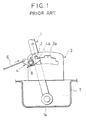
- a base portion 1a of a shift lever 1 is pivotally supported on a machine casing 7 and a positioning pin 2 is arranged on the shift lever 1 so as to freely move upwards and downwards.
- the positioning pin 2 is energized upwards by energizing means (not shown) at all times and can be moved downwards when a knob button (not shown) provided on the upper part of the shift lever 1 is pressed.
- a bell-crank 4 with an engaging slot 4a is pivotally supported on a positioning plate 3 and is energized by a spring 8 at all times so as to rotate clockwise.
- the engaging slot 4a of the bell-crank 4 engages with the positioning pin 2 when the positioning pin 2 is at the parking position (P) of an opening 3a formed in the positioning plate 3. Further, a key-lock-cable 6 which operates in conjunction with a key-interlock mechanism (not shown) is connected to the bell-crank 4.
- the slot width of the engaging slot 4a of the bell-crank 4 is set larger than the diameter of the positioning pin 2 so as to freely move the positioning pin 2 upwards and downwards. Consequently, the play generated between the positioning pin 2 and the engaging slot 4a results in play being generated when the key-lock-cable 6 is pushed or pulled by the bell-crank 4, thereby causing the function of the key-interlock mechanism to deteriorate.
- the spring 8 is necessary to produce tension in the key-lock-cable 6 in the direction shown by the arrows in Fig. 1, whereby the positioning pin 2 and the bell-crank 4, respectively, are energized in substantially opposite directions.
- the upward energizing force on the positioning pin 2 must be set larger than the clockwise energizing force on the bell-crank 4 to produce tension in the key-lock-cable 6. Accordingly, the force to operate or press the knob button has to be relatively large, thereby resulting in poor operating characteristics in the shift lever 1.
- an object of the present invention is to solve the aforementioned problems in the prior art through the introduction of a shift lever apparatus which can prevent the malfunction of the key-interlock mechanism while improving the function thereof and which can improve the operating characteristics of the shift lever. According to the present invention, this object is attained by a shift lever apparatus with the features cited in the characterising portions of claims 1 and 3 respectively.
- the shift lever apparatus even if the user tries to move the positioning pin from the parking position (P) toward the running positions while pressing the positioning pin downwards in a state in which the engine key is removed from the key-interlock mechanism, the downward movement of the positioning pin is prevented by the second lever stabilized by the lock lever or by the lock lever itself. In this state, since the force to move the positioning pin is transmitted only to the second lever or to the lock lever and only a small force acts upon the first lever, the key-lock cable does not move or operate, thereby preventing the malfunction of the key-interlock mechanism.
- the positioning pin positioned at the parking position (P) is restrained by the first and second levers, there is no play between the positioning pin and the first and second levers, whereby the key-interlock mechanism can be precisely operated through the key-lock cable, thereby improving the function of the key-interlock mechanism.
- the force produced by the energizing means scarcely acts upon the positioning pin which is energized in the first direction. Specifically, there is no force acting upon the positioning pin in a second direction which is opposite to the first direction. Accordingly, it is possible to reduce the force for energizing the positioning pin in the first direction to a minimum. That is, it is possible to reduce the force for moving or shifting the shift lever to a minimum, thereby improving the operating characteristics of the shift lever.
- the second lever does not adversely rotate due to the second lever lock means. Accordingly, the second lever lock means can facilitate smooth movement of the positioning pin while preventing the positioning pin from deviating to a side of the second lever which is opposite to the side for restraining the positioning pin, thereby improving the operating characteristics of the shift lever.
- Fig. 1 is an explanatory elevational view of a shift lever apparatus according to a conventional example.
- Fig. 2 is an explanatory elevational view of a shift lever apparatus according to a first embodiment of the present invention.
- Fig. 3 is a partial elevational view of the shift lever apparatus illustrated in Fig. 2, showing the state in which a positioning pin is locked.
- Fig. 4 is an elevational view showing the state in which the positioning pin shown in Fig. 3 is unlocked.
- Fig. 5 is an elevational view showing the state in which the positioning pin is unlocked.
- Fig. 6 is a plan view of the shift lever apparatus in the state shown in Fig. 5.
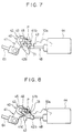
- Fig. 7 is an elevational view showing the state in which the positioning pin is unlocked.
- Fig. 8 is an elevational view showing the state in which the positioning pin is unlocked.
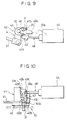
- Fig. 9 is an elevational view showing the state in which the positioning pin is locked.
- Fig. 10 is a plan view of the shift lever apparatus in the state shown in Fig. 9.
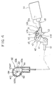
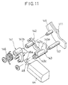
- Fig. 11 is an exploded perspective view of a shift lever apparatus according to a second embodiment of the present invention.
- Fig. 12 is a plan view of the shift lever apparatus shown in Fig. 11.
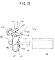
- Fig. 13 is a partial elevational view of the shift lever apparatus illustrated in Fig. 11, showing the state in which a positioning pin is locked.
- Fig. 14 is an elevational view of the shift lever apparatus, showing the state in which a positioning pin is unlocked.
- Fig. 15 is an explanatory elevational view of a shift lever apparatus, showing the state in which a positioning pin is locked, according to a third embodiment of the present invention.
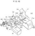
- Fig. 16 is an exploded perspective view of the shift lever apparatus illustrated in Fig. 15.
- Fig. 17 is an explanatory elevational view of a shift lever apparatus, showing the state in which the positioning pin shown in Fig. 15 is unlocked.
- Fig. 18 is a partial enlarged elevational view of the shift lever apparatus illustrated in Fig. 15, showing the state in which the positioning pin is locked.
- Fig. 19 is an elevational view of the shift lever apparatus, showing the positioning pin unlocked and moving downward.
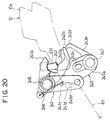
- Fig. 20 is an elevational view of the shift lever apparatus, showing the positioning pin at a lower position than in the state shown in Fig. 19.
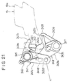
- Fig. 21 is an elevational view of the shift lever apparatus, showing the positioning pin at a lower position than in the state shown in Fig. 20.
- a shift lever apparatus E is used with an automatic transmission in a vehicle.
- the shift lever apparatus E includes a positioning pin 31 which is energized upwards at all times and which can engage with and can be released from an opening 10a having a plurality of positioning recesses formed in a positioning plate 10.
- the shift lever apparatus E includes a shift lever 30 which is pivotally supported on a machine casing 20, a lock mechanism 40 for preventing the positioning pin 31 positioned at a parking position (P) from moving downwards, and a key-interlock mechanism 60 operating in conjunction with the lock mechanism 40.
- the positioning plate 10 is arranged on the machine casing 20 which is secured to the vehicle body.
- the positioning plate 10 is formed with the opening 10a having the plurality of positioning recesses relatively adjacent to the outer periphery thereof.
- the positioning recesses correspond to parking (P), reverse, neutral, drive, second-speed, and first-speed positions, respectively.
- the parking position (P) is located at the leftmost side of the opening 10a as shown in Fig. 2.
- running positions in the opening 10a except the parking position (P) will be referred to as running positions.
- the base portion of the shift lever 30 which has a cylindrical form is pivotally supported on the machine casing 20 by a shaft 32.
- the positioning pin 31 is partly embedded in a rod (not shown) which is slidably arranged inside the shift lever 30 along the shift lever 30 and which is energized upwards by a rod spring (not shown) at all times.
- a knob 33 is secured to the upper end of the shift lever 30 and is provided with a knob button 34 which partly protrudes from the knob 33 and can be pressed toward the inside of the knob 33. When the knob button 34 is pressed against the force of the rod spring, the positioning pin 31 can move downwards.
- the lock mechanism 40 includes a first operation lever 41, a second operation lever 42, a lock lever 43, and an actuator 44, which are formed as a unit on a bracket 11 secured to the positioning plate 10.
- the first operation lever 41 has a bell-crank shape, specifically has an arm 41b and an arm 41c, and is pivotally supported at the base between the arm 41b and the arm 41c on the bracket 11 by a shaft 45.
- the arm 41b extends substantially to the right, namely toward the positioning pin 31, so that the bottom face of the arm 41 abuts the positioning pin 31 when the positioning pin 31 is positioned at the parking position (P).
- the distal end of the arm 41c of the first operation lever 41 is connected to the end of a key-lock cable 61 which is connected to the key-interlock mechanism 60, by a securing shaft.
- the key-lock cable 61 is a push-pull cable.
- the second operation lever 42 has a base and an arm 42b.
- the base of the second operation lever 42 is pivotally supported on the bracket 11 by the shaft 45 which also supports the first operation lever 41.
- the second operation lever 42 could be supported by a shaft other than the shaft 45.
- the arm 42b extends substantially to the right, namely toward the positioning pin 31, so as to be located under and facing the arm 41b of the first operation lever 41.
- the arm 42b has a projection 42d projecting in the direction in which the shaft 45 of the first and second operation levers 41, 42 extends, i.e., extending toward the lock lever 43, as shown in Fig. 6.
- the arm 41b of the first operation lever 41 and the arm 42b of the second operation lever 42 are energized by a helical torsion spring 46 wound around the shaft 45 so as to draw the arms 41b, 42b close together.
- the arm 41b and the arm 42b are constructed so as to press and face each other across the positioning pin 31 positioned at the parking position (P).
- the lock lever 43 has a bell-crank shape, and its base is pivotally supported on the bracket 11 by the shaft 47 which extends at right angles to the shaft 45.
- An arm 43b of the lock lever 43 is provided with a slot 43c with which a hook portion 48a provided in a plunger 48 of the actuator (which will be described later) 44 is engaged.
- the other arm 43d of the lock lever 43 is located at a position opposite to the bottom face of the projection 42d of the second operation lever 42 when the positioning pin 31 is at the parking position (P), in response to the rotation of the lock lever 43, as shown in Fig. 10.
- a projection 41d is provided in the first operation lever 41 to oppose against the arm 43b.
- the actuator 44 for example, a solenoid 44 with the plunger 48, is secured to the positioning plate 10.
- the plunger 48 which is partly contained inside the solenoid 42 is energized by a spring (not shown) so as to exit the solenoid 44.
- the hook portion 48a formed in the distal end of the plunger 48 is engaged with the slot 43c in the arm 43b of the lock lever 43 as shown in Fig. 6.
- the solenoid 44 is turned off when a brake pedal is pressed before the vehicle is started.
- the plunger 48 is caused to exit the solenoid 44 by the spring so as to rotate the lock lever 43 counterclockwise in Fig. 6 and to allow the arm 43d to be withdrawn from under the bottom face of the projection 42d of the second operation lever 42 which is positioned at a specific position when the positioning pin 31 is positioned at the parking position (P).
- a cylinder lock as the key-interlock mechanism 60, includes a key cylinder 62 containing a key rotor 63 into which an engine key is inserted and rotated.
- the key rotor 63 is rotatable to a lock position (LOCK) for locking the steering of the vehicle at which the engine key can be removed, an accessary position (ACC) for enabling use of electrical equipment in the vehicle with the engine stopped, an on position (ON) for operation of the engine, and a start position (START) for starting the engine.
- LOCK lock position
- ACC accessary position
- ON on position
- START start position
- the key cylinder 62 is provided thereinside with a stopper 64 which is connected to the first operation lever 41 through the key-lock cable 61.
- the stopper 64 can be moved deeply inside of the key cylinder 62 and can be positioned at a lock position set for preventing the key rotor 63 from moving from the on position (ON) toward the lock position (LOCK) as shown in Fig. 4 since the key-lock cable 61 is pushed toward the key-interlock mechanism 60.
- the key rotor 63 is provided with a restricting portion 63a which prevents the stopper 64 from moving toward the lock position of the stopper 73 when the key rotor 63 is rotated to the lock position (LOCK). Further, the key rotor 63 is provided with a position-restrict portion 63b which, when the stopper 73 is positioned at its lock position, prevents the stopper 73 from further moving beyond its lock position as shown in Fig. 4.
- first operation lever 41, the second operation lever 42, and the lock lever 43 which form the lock mechanism 40 may be directly secured to the positioning plate 10.
- the user while pressing the knob button 34, moves the shift lever 30 so that the positioning pin 31 is directed toward the parking position (P), as shown in Fig. 5. In this way, the positioning pin 31 abuts the upper face of the arm 42b of the second operation lever 42. In this state, the solenoid 44 is in the off state and energizes the plunger 48 so that the plunger 48 exits the solenoid 44. Further, the arm 43d of the lock lever 43 is maintained at the position at which the arm 43d is withdrawn from the bottom face of the projection 42d of the second operation lever 42 as shown in Fig. 6.
- the positioning pin 31 is located under the parking position (P) while the arm 42b of the second operation lever 42 is pressed against the spring force of the helical torsion spring 46 as shown in Fig. 7.
- the positioning pin 31 When the positioning pin 31 is then located closer to the parking position (P), the positioning pin 31 is restrained by the arm 41b of the first operation lever 41 and the arm 42b of the second operation lever 42. In this state, the force of the rod spring provided inside the shift lever 30 only acts upon the knob button 34.
- the positioning pin 31 engages the upper end of the opening 10a of the parking position (P) as shown in Fig. 9.
- the lever provided on the shift lever 30 abuts the contact point of the microswitch, the solenoid 44 is excited, and the plunger 48 enters the solenoid 44.
- the lock lever 43 rotates clockwise in Fig. 10 and the arm 43d of the lock lever 43 moves to a position at which the arm 43d abuts the bottom face of the projection 42d of the second operation lever 42.
- the positioning pin 31 is restrained by the arm 41b of the first operation lever 41 and the arm 42b of the second operation lever 42. Meanwhile, although the solenoid 44 remains turned off, the projection 41d of the first operation lever 41 presses the arm 43b of the lock lever 43 so as to rotate the lock lever 43 counterclockwise in Fig. 10. Thus, the arm 43d moves to a position at which the arm 43d abuts the bottom face of the projection 42d of the second operation lever 42, while locking the second operation lever 42, namely the shift lever 30.
- the engine key is inserted into the cylinder lock 60 and is rotated so that the key rotor 63 rotates toward the on position (ON).
- the restricting portion 63a is withdrawn from a position located along the direction in which the stopper 64 slides as shown in Fig. 4.
- the first operation lever 41 which is being pressed by the positioning pin 31, is stabilized in a position as shown in Fig. 3.
- the positioning pin 31 is moved from the running position toward the parking position (P) while the shift lever 30 is shifted as shown in Figs. 7-9.
- the lever on the shift lever 30 abuts the contact point of the microswitch.
- the solenoid 44 is turned on while causing the plunger 48 to enter the solenoid 44, whereby the lock lever 43 rotates clockwise in Fig. 10.
- the arm 43d of the lock lever 43 moves to a position at which the arm 43d abuts the bottom face of the projection 42d of the second operation lever 42 which presses the positioning pin 31 positioned at the parking position (P) upwards.
- the stopper 64 is pulled by the first operation lever 41 through the cable 61 so as to be at its unlocked position, whereby it becomes possible for the key rotor 63 to rotate toward the lock position (LOCK) as shown in Fig. 3. Finally, the engine key can be removed.
- the positioning pin 31 positioned at the parking position (P) is restrained by the first and second operation levers 41, 42, there is no play between the positioning pin 31 and the first and second operation levers 41, 42, whereby the key-interlock mechanism 60 can be precisely operated through the key-lock cable 61, thereby improving the function of the key-interlock mechanism 60.
- a lock lever 143 is pivotally supported by a shaft 147, and a first operation lever 141 and a second operation lever 142 are pivotally supported by a shaft 145 on the bracket 111.
- the shafts 147, 145 extend in the same direction.
- the lock lever 143 is provided on the upper part thereof with a lock portion 143e forming a part of a circle of which the shaft 147 is the center.
- the lock lever 143 and the first and second operation levers 141, 142 are constructed so that the positioning pin 31 positioned at the parking position (P) can be directly locked by the lock portion 143e of the lock lever 143.
- the third embodiment according to the present invention which is an embodiment further developed based upon the configuration of the second embodiment, will be explained hereinafter with reference to Figs. 15-21.
- the shift lever apparatus E' includes a lock mechanism 240 for preventing the positioning pin 231 positioned at a parking position (P) from moving downwards, and a key-interlock mechanism 60 which operates in conjunction with the lock mechanism 240.
- the lock mechanism 240 includes a key-lock lever 241, a support lever 242, a lock lever 243, and the actuator 44 and is formed as a unit on a bracket 211 secured to the positioning plate 10.
- the key-lock lever 241 has a bell-crank shape, specifically has an arm 241b and an arm 241c, and is pivotally supported at the base thereof on the bracket 211 by a shaft 245.
- the arm 241b extends substantially to the right, namely toward the positioning pin 231, so that the bottom face of the arm 241 abuts the positioning pin 231 when the positioning pin 231 is positioned at the parking position (P).
- the distal end of the arm 241c of the key-lock lever 241 is connected to the end of a key-lock cable 61 which is connected to the key-interlock mechanism 60, by a securing shaft.
- the support lever 242 has a base and an arm 242a.
- the base of the support lever 242 is pivotally supported on the bracket 211 by the shaft 245 (by which the key-lock lever 241 is also supported).
- the arm 242a extends substantially to the right, namely toward the positioning pin 231, so as to be located under and facing the arm 241b of the key-lock lever 241. That is, the arm 241b of the key-lock lever 241 and the arm 242a of the support lever 242, respectively, are located in the upper side and the lower side of the positioning pin 231 positioned at the parking position (P).
- the arm 241b of the key-lock lever 241 and the arm 242a of the support lever 242 are energized by a helical torsion spring 246 wound around a boss section 241a formed in the base of key-lock lever 241 so as to be drawn close together.
- a helical torsion spring 246 wound around a boss section 241a formed in the base of key-lock lever 241 so as to be drawn close together.
- the lock lever 243 has a bell-crank shape, and its base is pivotally supported on the bracket 211 by the shaft 247.
- the top face of an arm 243a of the lock lever 243 forms a lock portion 243b with a part of a circle circling the axis of the shaft 247.
- the left side face of the arm 243a of the lock lever 243 forms a cam face 243d, which abuts a pin 241d embedded in the arm 241c of the key-lock lever 241.
- the cam face 243d serves to rotate the lock lever 243, while operating in conjunction with the key-lock lever 241, so as to allow the positioning pin 231 positioned at the parking position (P) to move downwards.
- the other arm 243e of the lock lever 243 is provided with a hook portion 243f which is constructed so as to engage a hook portion 242b formed at the distal end of the arm 242a of the support lever 242 when the lock mechanism 240 is in the unlocking state.
- the solenoid 44 is housed inside a solenoid case 211a which is integrally formed with the bracket 211 as shown in Fig. 16.
- the hook portion 48a of the plunger 48 of the solenoid 44 engages a slot 243c provided in the base of the lock lever 243.
- the solenoid 44 in its on state, i.e., in the state in which the plunger 48 enters the solenoid 44, rotates the lock lever 243 clockwise so as to move the lock portion 243b of the lock lever 243 opposite to the positioning pin 231 positioned at the parking position (P) as shown in Figs. 15 and 18.
- the solenoid 44 in its off state, i.e., in the state in which the plunger 48 exits the solenoid 44, rotates the lock lever 243 counterclockwise so as to withdraw the lock portion 243b from the way on which the positioning pin 231 moves from the parking position (P) as shown in Figs. 17, 20, and 21.
- the key-lock lever 241, the support lever 242, the lock lever 243, and the solenoid 44 which form the lock mechanism 240 may be directly secured to the positioning plate 10 without utilizing the bracket 211.
- the key-lock cable 61 is pulled toward the lock mechanism 240 or the key-lock lever 241 by the key-lock lever 241. Since the key-lock lever 241 is located at a position shown in Fig. 18, the pin 241d of the key-lock lever 241 abuts and can press the cam face 243d of the arm 243a of the lock lever 243, thereby preventing the lock lever 243 from rotating counterclockwise. Consequently, the lock lever 243 is stabilized at the position at which the lock portion 243b opposes the positioning pin 231. In this state, the stopper 64 is pulled by the key-lock lever 241 through the key-lock cable 61 and is located at the unlock position, allowing the key rotor 63 to rotate as shown in Fig. 15.
- the positioning pin 231 is prevented from being moved downwards since the positioning pin 231 abuts the lock portion 243b of the lock lever 243 as shown in Fig. 19. Accordingly, the shift lever 30 can be prevented from being shifted to allow the positioning pin 231 to move from the parking position (P) toward the running positions.
- the engine key is inserted into the cylinder lock 60 and is rotated so that the key rotor 63 rotates toward the on position (ON).
- the restricting portion 63a is withdrawn from a position located along the direction in which the stopper 64 slides, as shown in Fig. 17, thereby allowing the stopper 64 to move upwards.
- the key-lock lever 241, which is being pressed by the positioning pin 231 is stabilized in a position as shown in Figs. 15 and 18.
- the solenoid 44 is turned on (i.e., the plunger 48 enters the solenoid 44), whereby the lock lever 243 is maintained at the position at which the the lock lever 243 locks the positioning pin 231.
- the shift lever 30 can be shifted to move the positioning pin 231 from the parking position (P) toward the running positions, thereby allowing the vehicle to run.
Landscapes
- Engineering & Computer Science (AREA)
- Mechanical Engineering (AREA)
- General Engineering & Computer Science (AREA)
- Arrangement Or Mounting Of Control Devices For Change-Speed Gearing (AREA)
- Control Of Transmission Device (AREA)
Claims (6)
- Schalthebelvorrichtung (E) für ein Fahrzeug, die folgendes aufweist:eine Positionsplatte (10) mit einer Parkposition (P) und einer Fahrposition;einen drehbar an einem Fahrzeugkörper gehaltenen und mit einer Stange versehenen Schalthebel (30), wobei die Stange in einer ersten Richtung von einem Energiezufuhrelement mit Energie beaufschlagt ist;einem an der Stange vorgesehenen Positionsstift (31), der zwischen der Parkposition (P) und der Fahrposition bewegbar ist;einen an der Positionsplatte (10) gehaltenen ersten Hebel (41), der mit einem Arm (41b) versehen ist, wobei der Arm (41b) des ersten Hebels (41) bei in der Parkposition (P) angeordneten Positionsstift (31) über dem Positionsstift (31) angeordnet ist;einem drehbar auf einer Achse (47) gehaltenen und mit einem Arm (43d) versehenen Sperrhebel (43), wobei der Arm (43d) des Sperrhebels (43) zum Sperren des Positionsstifts (31) in der Parkposition (P) schaltbar ist;ein mit dem Sperrhebel (43) verbundenes Stellorgan, das den Sperrhebel (43) betätigt, um denselben in vorbestimmte Richtungen zu drehen;einen Schlüsselsperrmechanismus (60) zum Arretieren und Lösen des Fahrzeugschlüssels,dadurch gekennzeichnet,daß der erste Hebel (41) an der Positionsplatte (10) mittels einer Achse (45) drehbar gehalten ist;ein zweiter Hebel (42) an der Positionsplatte (10) mittels einer Welle (45) drehbar gehalten und mit einem Arm (42b) versehen ist, wobei der Arm (42b) des zweiten Hebels (42) in der Parkposition (P) unter dem Positionsstift (31) angeordnet ist;ein Energiezufuhrmittel (46) für die Beaufschlagung des ersten und zweiten Hebels (41, 42) mit Energie vorgesehen ist, um die Arme (41b, 42b) des ersten und zweiten Hebels (41, 42) nahe zueinander zu drehen und den in der Parkposition (P) befindlichen Positionsstift (31) zurückzuhalten;der Sperrhebel (43) in einem rechten Winkel zu der Achse (45) des zweiten Hebels (42) ist;der Arm (43d) des Sperrhebels (43) durch Drücken mittels des ersten Hebels (41) mit dem zweiten Hebel (42) in Eingriff bringbar ist, so daß der zweite Hebel (42) in der Parkposition (P) unter dem Positionsstift (31) festgelegt ist, um den Positionsstift (31) in der Parkposition (P) zu sperren; undder Schlüsselsperrmechanismus (60) mit einem Kabel (61) mit dem ersten Hebel (41) durch ein Schlüsselsperrkabel (61) verbunden ist.
- Schalthebelvorrichtung (E) nach Anspruch 1,
dadurch gekennzeichnet,
daß die ersten und zweiten Hebel (41, 42) an derselben Achse (45) abgestützt sind, der zweite Hebel (42) einen in Erstreckungsrichtung der Achse (45) des ersten und zweiten Hebels (41, 42) vorspringenden Ansatz hat, der Arm (43d) des Sperrhebels (43) in den Ansatz des zweiten Hebels (42) eingreift, der erste Hebel (41) eine Kniehebelform hat, bei der der andere Arm (41c) mit dem Schlüsselsperrkabel (61) verbunden ist und der Sperrhebel (43) eine Kniehebelform hat, bei der der andere Arm (43b) des Sperrhebels (43) mit einem Ende des Stellorgans (44) verbunden ist. - Schalthebelvorrichtung (E') für ein Fahrzeug, die folgendes aufweist:eine Positionsplatte (10) mit einer Parkposition (P) und einer Fahrposition;einen drehbar an einem Fahrzeugkörper gehaltenen und mit einer Stange versehenen Schalthebel, wobei die Stange in einer ersten Richtung durch ein Energiezufuhrmittel mit Energie beaufschlagt ist;einen an der Stange vorgesehenen und zwischen der Parkposition (P) und einer Fahrposition bewegbaren Positionsstift (31);einen an der Positionsplatte (10) gehaltenen und mit einem Arm (241b) versehenen ersten Hebel (241), wobei der Arm (241b) des ersten Hebels (241) bei in der Parkposition (P) befindlichem Positionsstift (231) über demselben positioniert ist;einen drehbar an einer Achse (247) gehaltenen und mit einem Arm (243d) versehenen Sperrhebel (243), wobei der Arm (243d) des Sperrhebels in der Parkposition (P) zum Arretieren des Positionsstiftes (231) in Eingriff bringbar ist;ein mit dem Sperrhebel (243) verbundenes Stellorgan (44), das den Sperrhebel (243) betätigt, um den Sperrhebel (243) in vorbestimmte Richtungen zu drehen;einen Schlüsselsperrmechanismus (60) zum Arretieren und Lösen des Fahrzeugschlüssels,dadurch gekennzeichnet,
daßder erste Hebel (241) mittels einer Achse (245) drehbar an der Positionsplatte (10) gehalten ist;ein zweiter Hebel (242) mittels einer Achse (245) drehbar an der Positionsplatte (10) gehalten und mit einem Arm (242a) versehen ist, wobei der Arm des zweiten Hebels (242) in der Parkposition (P) unter dem Positionsstift (231) positioniert ist;ein Energiezufuhrmittel zum Beaufschlagen des ersten und zweiten Hebels (241, 242) mit Energie vorgesehen ist, um die Arme (241b, 242a) des ersten und zweiten Hebels (241, 242) nahe zueinander zu drehen und den Positionierstift (231) in der Parkposition (P) zurückzuhalten;die Achse (247) des Sperrhebels (243) parallel zu der Achse (245) des zweiten Hebels (242) ist;der Arm (243b) des Sperrhebels (243) mittels des ersten Hebel (241) gedrückt wird, wenn der Positionsstift (231) in der Parkposition (P) positioniert ist, um unter dem Positionsstift (231) festhalten werden und den Positionsstift (231) in der Parkposition (P) zu arretieren; undder Schlüsselsperrmechanismus (60) mit einem Kabel (61) mit dem ersten Hebel (241) durch ein Schlüsselsperrkabel verbunden ist. - Schalthebelvorrichtung nach Anspruch 3,
dadurch gekennzeichnet,
daß der erste und der zweite Hebel durch die selbe Achse (245) gehalten sind, der Sperrhebel (243) Kniehebelform hat, in der der andere Arm des Sperrhebels (243) mit einem Ende des Stellorgans verbunden ist und der erste Hebel (241) eine Kniehebelform hat, in der der andere Arm (241c) mit dem Schlüsselsperrkabel (61) verbunden ist, und wobei der andere Arm (241c) des ersten Hebels (241) einen Ansatz (241d) hat, der gegen eine Seitenfläche (243d) des Arms des Sperrhebels (243) stößt, wenn der Positionsstift (231) in der Parkposition angeordnet ist. - Schalthebelvorrichtung nach Anspruch 4,
dadurch gekennzeichnet,
daß der zweite Hebel (242) und der Sperrhebel (243) zweite Hebelsperrmittel (243f, 242b) hat zum Verhindern des Drehens des zweiten Hebels (42) wenn der Positionsstift (231) von der Fahrposition zu der Parkposition bewegt wird. - Schalthebelvorrichtung nach Anspruch 5,
dadurch gekennzeichnet,
daß das zweite Hebelsperrmittel ein an einem Ende des anderen Arms des Sperrhebels (243) vorgesehenes Hakenteil (243f) und ein an einem Ende des zweiten Hebels (242) vorgesehenes Hakenteil (242b) beinhaltet, so daß die Hakenteile miteinander in Eingriff gelangen können.
Applications Claiming Priority (4)
| Application Number | Priority Date | Filing Date | Title |
|---|---|---|---|
| JP37942/93 | 1993-02-26 | ||
| JP03794293A JP3212737B2 (ja) | 1993-02-26 | 1993-02-26 | シフトレバー装置 |
| JP102106/93 | 1993-04-28 | ||
| JP10210693A JP2905356B2 (ja) | 1993-04-28 | 1993-04-28 | シフトレバー装置 |
Publications (3)
| Publication Number | Publication Date |
|---|---|
| EP0612640A2 EP0612640A2 (de) | 1994-08-31 |
| EP0612640A3 EP0612640A3 (de) | 1995-02-08 |
| EP0612640B1 true EP0612640B1 (de) | 1997-01-15 |
Family
ID=26377119
Family Applications (1)
| Application Number | Title | Priority Date | Filing Date |
|---|---|---|---|
| EP94102903A Expired - Lifetime EP0612640B1 (de) | 1993-02-26 | 1994-02-25 | Schalthebel |
Country Status (3)
| Country | Link |
|---|---|
| US (1) | US5421792A (de) |
| EP (1) | EP0612640B1 (de) |
| DE (1) | DE69401443T2 (de) |
Families Citing this family (24)
| Publication number | Priority date | Publication date | Assignee | Title |
|---|---|---|---|---|
| JP3449763B2 (ja) * | 1993-11-30 | 2003-09-22 | 富士機工株式会社 | シフトレバー装置 |
| JPH07151224A (ja) * | 1993-11-30 | 1995-06-13 | Fuji Kiko Co Ltd | 自動変速機の操作装置 |
| JPH07266908A (ja) * | 1994-03-31 | 1995-10-17 | Fuji Kiko Co Ltd | シフトレバー装置 |
| JP3130732B2 (ja) * | 1994-06-30 | 2001-01-31 | 富士機工株式会社 | 自動変速機操作装置のインターロック機構 |
| US5566581A (en) * | 1994-10-11 | 1996-10-22 | Dura Automotive Systems, Inc. | Manual transmission and ignition interlock |
| US5924540A (en) * | 1995-11-22 | 1999-07-20 | Daewoo Motor Co., Ltd. | Selector lever lock device for an automatic transmission in a motor vehicle |
| US6237499B1 (en) | 1996-06-11 | 2001-05-29 | Mckoy Errol W. | Watercraft amusement ride |
| US5861800A (en) * | 1996-06-12 | 1999-01-19 | Chrysler Corporation | Ignition interlock and PRNDL indicator powering switch |
| JP3335529B2 (ja) * | 1996-10-16 | 2002-10-21 | 富士機工株式会社 | シフトレバー装置 |
| US6082217A (en) * | 1998-08-11 | 2000-07-04 | Teleflex Incorporated | Brake transmission shift interlock assembly |
| DE10146776B4 (de) * | 2001-09-22 | 2006-10-19 | Daimlerchrysler Ag | Wählhebelführung für Automatikgetriebe |
| DE10150718B4 (de) * | 2001-10-13 | 2006-05-04 | Kai Schmidt | Sperreinrichtung für einen schwenkbaren Wählhebel eines Automatikgetriebes sowie Verfahren zum Sperren eines Wählhebels |
| US20050044979A1 (en) * | 2002-06-20 | 2005-03-03 | Fort William H. | Park pawl actuator |
| US20040168537A1 (en) * | 2003-02-28 | 2004-09-02 | Teleflex Incorporated | Shifter assembly for an automatic transmission |
| JP4518869B2 (ja) * | 2004-08-23 | 2010-08-04 | トヨタ自動車株式会社 | 車両用シフトロック装置 |
| DE102005033510B4 (de) * | 2005-07-14 | 2012-03-22 | Zf Friedrichshafen Ag | Betätigungseinrichtung mit Schaltsperre |
| DE102007024030B4 (de) * | 2007-05-22 | 2011-01-05 | Zf Friedrichshafen Ag | Betätigungseinrichtung mit Sperrvorrichtung |
| JP5142285B2 (ja) * | 2008-03-27 | 2013-02-13 | 現代自動車株式会社 | 自動変速機付き車両の変速レバーロック装置 |
| KR20100116772A (ko) | 2009-04-23 | 2010-11-02 | 현대자동차주식회사 | 주차 브레이크 장치 |
| US20140157943A1 (en) * | 2012-12-07 | 2014-06-12 | Kavlico Corporation | Rotatable and stationary gates for movement control |
| CN103527764B (zh) * | 2013-11-04 | 2016-02-03 | 重庆青山工业有限责任公司 | 汽车换档器定位装置 |
| US10267417B2 (en) | 2015-08-26 | 2019-04-23 | Ghsp, Inc. | Shifter with noiseless BITSI shift lever control |
| US20170335957A1 (en) * | 2016-05-17 | 2017-11-23 | Dura Operating, Llc | Transmission shifter with multi-position lockout |
| EP3511597B1 (de) * | 2018-01-15 | 2020-02-26 | FCA Italy S.p.A. | Steuerungsvorrichtung für einen fahrzeugschalthebel |
Family Cites Families (8)
| Publication number | Priority date | Publication date | Assignee | Title |
|---|---|---|---|---|
| JPS60135352A (ja) * | 1984-03-27 | 1985-07-18 | Isuzu Motors Ltd | 変速レバーとハンドルのロック装置 |
| AU593425B2 (en) * | 1987-09-14 | 1990-02-08 | Tokai-Rika-Denki-Seisakusho Kabushiki Kaisha | Device for locking shift lever of automatic transmission |
| AU605010B2 (en) * | 1988-01-14 | 1991-01-03 | Kabushiki Kaisha Tokai-Rika-Denki-Seisakusho | Transmission operating apparatus |
| US5251723A (en) * | 1989-02-23 | 1993-10-12 | Sparton Corporation | Service brake and shift lever interlock system |
| SE467472B (sv) * | 1989-10-02 | 1992-07-20 | Volvo Ab | Vaexelreglage foer fordon med automatvaexellaador |
| JP2842951B2 (ja) * | 1991-03-29 | 1999-01-06 | 日産自動車株式会社 | 自動変速機のキーインターロック装置 |
| JPH0650415A (ja) * | 1992-07-28 | 1994-02-22 | Fuji Kiko Co Ltd | シフトレバー装置 |
| DE4225182A1 (de) * | 1992-07-30 | 1994-02-03 | Porsche Ag | Vorrichtung zur Verriegelung des Zündschlüssels eines Kraftfahrzeuges mit dem Wählhebel eines Automatikgetriebes |
-
1994
- 1994-02-23 US US08/201,163 patent/US5421792A/en not_active Expired - Fee Related
- 1994-02-25 DE DE69401443T patent/DE69401443T2/de not_active Expired - Fee Related
- 1994-02-25 EP EP94102903A patent/EP0612640B1/de not_active Expired - Lifetime
Also Published As
| Publication number | Publication date |
|---|---|
| US5421792A (en) | 1995-06-06 |
| DE69401443T2 (de) | 1997-04-30 |
| EP0612640A3 (de) | 1995-02-08 |
| EP0612640A2 (de) | 1994-08-31 |
| DE69401443D1 (de) | 1997-02-27 |
Similar Documents
| Publication | Publication Date | Title |
|---|---|---|
| EP0612640B1 (de) | Schalthebel | |
| KR910007749Y1 (ko) | 변속레버용 로크장치 | |
| JPH071317Y2 (ja) | 車両用セレクタレバー装置 | |
| JP2713971B2 (ja) | 自動変速機の操作装置 | |
| EP0506121B1 (de) | Steuerungsvorrichtung für ein Kraftfahrzeugzündschloss und eine Getriebeschaltverriegelung | |
| US5379871A (en) | Shift lever apparatus | |
| US5794469A (en) | Steering lock device | |
| US20070068325A1 (en) | Shift mechanism for a vehicle | |
| JP3822289B2 (ja) | 車両用シフトロック装置 | |
| JPH0452133Y2 (de) | ||
| JPH06249327A (ja) | シフトレバー装置 | |
| JPH0533374Y2 (de) | ||
| JP3061432B2 (ja) | 自動変速機のセレクトレバーロック装置 | |
| JPH0738763Y2 (ja) | オートマチツク車用シフトレバー制御装置 | |
| JPH0710652B2 (ja) | 自動変速機のセレクトレバーロック装置 | |
| JP3920434B2 (ja) | シフトレバー装置 | |
| EP0823575B1 (de) | Schaltsperre für Lenkradschalthebel-Vorrichtung für automatisches Getriebe | |
| JPH01257631A (ja) | 自動変速機の操作装置 | |
| JPH0742851Y2 (ja) | セレクタレバーのロック装置 | |
| JP3930109B2 (ja) | シフトレバー装置 | |
| JPH0448356Y2 (de) | ||
| JP3061431B2 (ja) | 自動変速機のセレクトレバーロック装置 | |
| JPH0650416A (ja) | シフトレバー装置 | |
| JP2849150B2 (ja) | ステアリングロック装置 | |
| JP2571722B2 (ja) | ステアリングロック装置 |
Legal Events
| Date | Code | Title | Description |
|---|---|---|---|
| PUAI | Public reference made under article 153(3) epc to a published international application that has entered the european phase |
Free format text: ORIGINAL CODE: 0009012 |
|
| 17P | Request for examination filed |
Effective date: 19940225 |
|
| AK | Designated contracting states |
Kind code of ref document: A2 Designated state(s): DE FR GB SE |
|
| PUAL | Search report despatched |
Free format text: ORIGINAL CODE: 0009013 |
|
| AK | Designated contracting states |
Kind code of ref document: A3 Designated state(s): DE FR GB SE |
|
| 17Q | First examination report despatched |
Effective date: 19950921 |
|
| GRAG | Despatch of communication of intention to grant |
Free format text: ORIGINAL CODE: EPIDOS AGRA |
|
| GRAH | Despatch of communication of intention to grant a patent |
Free format text: ORIGINAL CODE: EPIDOS IGRA |
|
| GRAH | Despatch of communication of intention to grant a patent |
Free format text: ORIGINAL CODE: EPIDOS IGRA |
|
| GRAA | (expected) grant |
Free format text: ORIGINAL CODE: 0009210 |
|
| AK | Designated contracting states |
Kind code of ref document: B1 Designated state(s): DE FR GB SE |
|
| REF | Corresponds to: |
Ref document number: 69401443 Country of ref document: DE Date of ref document: 19970227 |
|
| ET | Fr: translation filed | ||
| PLBE | No opposition filed within time limit |
Free format text: ORIGINAL CODE: 0009261 |
|
| STAA | Information on the status of an ep patent application or granted ep patent |
Free format text: STATUS: NO OPPOSITION FILED WITHIN TIME LIMIT |
|
| 26N | No opposition filed | ||
| PGFP | Annual fee paid to national office [announced via postgrant information from national office to epo] |
Ref country code: SE Payment date: 20010221 Year of fee payment: 8 |
|
| PGFP | Annual fee paid to national office [announced via postgrant information from national office to epo] |
Ref country code: GB Payment date: 20010227 Year of fee payment: 8 |
|
| REG | Reference to a national code |
Ref country code: GB Ref legal event code: IF02 |
|
| PG25 | Lapsed in a contracting state [announced via postgrant information from national office to epo] |
Ref country code: GB Free format text: LAPSE BECAUSE OF NON-PAYMENT OF DUE FEES Effective date: 20020225 |
|
| PG25 | Lapsed in a contracting state [announced via postgrant information from national office to epo] |
Ref country code: SE Free format text: LAPSE BECAUSE OF NON-PAYMENT OF DUE FEES Effective date: 20020226 |
|
| EUG | Se: european patent has lapsed |
Ref document number: 94102903.5 |
|
| GBPC | Gb: european patent ceased through non-payment of renewal fee |
Effective date: 20020225 |
|
| PGFP | Annual fee paid to national office [announced via postgrant information from national office to epo] |
Ref country code: FR Payment date: 20060217 Year of fee payment: 13 |
|
| PGFP | Annual fee paid to national office [announced via postgrant information from national office to epo] |
Ref country code: DE Payment date: 20060330 Year of fee payment: 13 |
|
| REG | Reference to a national code |
Ref country code: FR Ref legal event code: ST Effective date: 20071030 |
|
| PG25 | Lapsed in a contracting state [announced via postgrant information from national office to epo] |
Ref country code: DE Free format text: LAPSE BECAUSE OF NON-PAYMENT OF DUE FEES Effective date: 20070901 |
|
| PG25 | Lapsed in a contracting state [announced via postgrant information from national office to epo] |
Ref country code: FR Free format text: LAPSE BECAUSE OF NON-PAYMENT OF DUE FEES Effective date: 20070228 |