EP0599053B1 - Stickmaschinen- Gestell - Google Patents
Stickmaschinen- Gestell Download PDFInfo
- Publication number
- EP0599053B1 EP0599053B1 EP93116929A EP93116929A EP0599053B1 EP 0599053 B1 EP0599053 B1 EP 0599053B1 EP 93116929 A EP93116929 A EP 93116929A EP 93116929 A EP93116929 A EP 93116929A EP 0599053 B1 EP0599053 B1 EP 0599053B1
- Authority
- EP
- European Patent Office
- Prior art keywords
- frame
- machine
- spars
- open
- embroidering
- Prior art date
- Legal status (The legal status is an assumption and is not a legal conclusion. Google has not performed a legal analysis and makes no representation as to the accuracy of the status listed.)
- Revoked
Links
- 238000009956 embroidering Methods 0.000 title claims abstract description 13
- 239000004744 fabric Substances 0.000 claims abstract description 11
- 238000013016 damping Methods 0.000 claims description 2
- 238000010276 construction Methods 0.000 description 7
- 238000000926 separation method Methods 0.000 description 4
- 238000009434 installation Methods 0.000 description 2
- 239000000463 material Substances 0.000 description 2
- 238000004873 anchoring Methods 0.000 description 1
- 230000000712 assembly Effects 0.000 description 1
- 238000000429 assembly Methods 0.000 description 1
- 230000000694 effects Effects 0.000 description 1
- 230000008030 elimination Effects 0.000 description 1
- 238000003379 elimination reaction Methods 0.000 description 1
- 238000005516 engineering process Methods 0.000 description 1
- 239000002689 soil Substances 0.000 description 1
Images

Classifications
-
- D—TEXTILES; PAPER
- D05—SEWING; EMBROIDERING; TUFTING
- D05C—EMBROIDERING; TUFTING
- D05C1/00—Apparatus, devices, or tools for hand embroidering
- D05C1/02—Work frames
-
- D—TEXTILES; PAPER
- D05—SEWING; EMBROIDERING; TUFTING
- D05C—EMBROIDERING; TUFTING
- D05C3/00—General types of embroidering machines
- D05C3/04—General types of embroidering machines with horizontal needles
Definitions
- the present invention relates to an embroidery machine with a plurality of embroidery sites, in particular a machine frame, on which the Embroidery points in a horizontal arrangement in one or more rows are arranged one above the other.
- Such large embroidery machines of 10m, 15m to 21m embroidery length have been used since long two-story built, i.e. there will be two horizontal rows of Embroidery points and, accordingly, two fabric coupons to be embroidered arranged one above the other. This will double the number of stitches per minute. or reached per hour compared to a one-story machine. Since the Embroidery height (the height of the fabric to be embroidered in one setup) for reasons of performance increase of originally less than 40 cm The large embroidery machines were expanded to 120 cm and more thereby always higher.
- This conventional structure also forces the machines to To be installed on site, since a large embroidery machine is only together forms a stable unit with the foundation.
- the pre-assembly at Manufacturer remains on smaller, closed assemblies limited.
- the final assembly at the customer extends over 6 up to 12 weeks.
- the patent DE-C-230 960 describes an arrangement of with their long sides facing each other, standing side by side Embroidery machines, with the front bulkhead halves of one Machine only with the rear transverse wall halves of the neighboring one Machine are connected to a common rigid whole. The transverse wall halves of a machine are not together connected.
- the construction described has the disadvantage that the freedom of movement of the operator between the individual Machines is restricted.
- US-A-2,649,065 relates to a horizontal embroidery machine and vertically movable frame, the frame of the Machine consists of four vertical posts, each over longitudinal connectors and cross connectors attached to the top are interconnected.
- GB-A-25,531 relates to an embroidery machine with a variety of upright frame elements, which are relatively small Distance next to each other, across the longitudinal direction of the machine are arranged.
- the frame elements are above one another Longitudinal connector connected, in one embodiment the Top of the frame is covered by a side member. In another embodiment, the frame elements are on the top of each connected by cross connector.
- the front and back are each made by a frame End wall completed. The machine frame is neither on the front pages are still completely open at the top, but through an end wall or upper longitudinal or cross member closed.
- the invention has the task of a large embroidery machine type mentioned so that at about comparable performance a lower height is achieved and that an elaborate foundation can be dispensed with.
- An essential feature of the invention is that an im essentially open U-shaped frame is provided. So that according to the invention single-storey construction proposed that can be strung together and thereby avoiding the large construction heights, their disadvantages described in the introduction to the description above were.
- the embroidery machine according to the invention has approximately the same performance achieved as with conventional embroidery machines with a two-story structure.
- the U-channel of the machine frame which is open on both sides, now enables Tenter frame constructions in which the fabric to be embroidered on a Is fed into the machine and discharged on the other.
- the pre-assembly module consists of a lower support 1, which, as a paired carrier, holds two side stands 2 between them, which side stand in connection with the lower straps 1 one after Form U-frame 16 open at the top.
- the lower support 1 can also be made in one piece.
- U-frames 16 There are several such U-frames 16 side by side, the are connected to one another by horizontally extending longitudinal beams 3.
- the longitudinal members 3 are here with their end faces on the assigned Parts 1,2 attached, e.g. B. by screwing.
- the upper side members are called cheeks 3a and on these cheeks the embroidery tools, such as. B. boat, needle and drill arranged.
- the entire pre-assembly module now shows a longitudinal channel 14, in the area (see FIG. 2) of which the shuttle, needle and drill are arranged.
- the lower beams 1 of the preassembly module are on foundation plates 9 mounted as height-adjustable vibration damping elements can be trained.
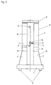
- Figure 2 shows the extended by an upper, U-shaped frame Pre-assembly module of Figure 1 in front view.
- the top, U-shaped Frame consists of the vertical supports 4 and the parallel to them extending side supports 7, which in their upper area by upper Cross connections 8 are interconnected.
- the embroidery machine frame consists of an open one lower, U-shaped frame and an upper, U-shaped frame, with the two U-legs facing each other are connected to each other at the end.
- the individual tools such as shuttle 11, needle 12 and drill 13 are as described above on the longitudinal direction extending cheeks 3a arranged.
- the embroidery machine can only consist of one U-shaped, upward open pre-assembly module, which frame already the required rigidity and Has vibration stability.
- the invention consists of one Open at the top, U-shaped frame and in a further training this is U-shaped frame open to the top by a second U-shaped frame Open frame added below. Due to the described modular structure there is now for the first time the possibility that one in the longitudinal direction can continue to connect pre-modules according to Figure 1 because the intended Separation points 5 are suitable for connection.
Landscapes
- Engineering & Computer Science (AREA)
- Textile Engineering (AREA)
- Sewing Machines And Sewing (AREA)
- Conveying And Assembling Of Building Elements In Situ (AREA)
Description
- Figur 1:
- die perspektivische Ansicht des Maschinengestells, wobei ein Vormontage-Modul gezeigt ist;
- Figur 2:
- Stirnansicht eines Vormontage-Moduls, welches durch einen oberen U-Spant zu einem geschlossenen Rahmen ergänzt ist.
Das gesamte Vormontagemodul zeigt nun einen in Längsrichtung verlaufenden, mittleren Kanal 14, in dessen Bereich (vergl. Figur 2) die genannten Schiffchen, Nadel und Bohrer angeordnet werden.
- 1
- unterer Träger
- 2
- Seitenständer
- 3
- Längsträger
- 3a
- Wangen
- 4
- vertikale Stützen
- 5
- Anschlüße für weitere Montagemodule
- 6
- Trennstelle der vertikalen Stützen
- 7
- Seitenstütze
- 8
- obere Querverbindung
- 9
- Fundamentplatten
- 10
- Stoffwellen des Spannrahmens
- 11
- Schiffchen
- 12
- Nadel
- 13
- Bohrer
- 14
- Kanal
- 15
- Stirnseiten
- 16
- U-förmige Spanten, nach oben offen
- 17
- U-förmige Spanten, nach unten offen
Claims (6)
- Stickmaschine mit horizontaler Anordnung einer Vielzahl von Stickstellen, welche in gleichem Abstand nebeneinander mit jeweils einer Nadel und den dazugehörenden Stickwerkzeugen, wie z. B. Bohrer, Fadenleiter, Stoffdrücker, Schiffchen, weitere maschenbildende Nadeln, welche sich teilweise auf der Vorder- und der Hinterseite eines Stoffspannrahmens gegenüberliegend in einer oder mehreren Reihen übereinander an einem Maschinengestell angeordnet sind,
dadurch gekennzeichnet, daß das Maschinengestell einen im wesentlichen U-förmig nach oben offenen Querschnitt aufweist, wobei mindestens zwei im wesentlichen vertikale nach oben offene U-Spanten (16) durch Längsträger (3,3a) miteinander verbunden sind und in Maschinenlängsrichtung einen an den Stirnseiten (15) und oben offenen Kanal (14) ausbilden, in welchem der Stoffspannrahmen (10) bewegbar angeordnet ist, wobei auf der Rückseite der Maschine, auf den die U-Spanten (16) verbindenen Längsträger (3a), vertikale Stützen (4) zur Führung und Bewegung des Spannrahmens befestigt sind. - Stickmaschine nach Anspruch 1, dadurch gekennzeichnet, daß die U-förmigen Spanten (16) aus jeweils zwei Seitenständern (2) und einem oder zwei unteren Trägern (1) aufgebaut sind, wobei die Seitenständer (2) in horizontalem Abstand zueinander zwischen den unteren Trägern (1) oder auf dem unteren Träger befestigt sind.
- Stickmaschine nach Anspruch 1, dadurch gekennzeichnet, daß nach unten offene U-förmige Spanten (17) derart auf dem Gestell angeordnet vorgesehen sind, daß diese zusammen mit den nach oben offenen Spanten (16) Rahmen mit rechteckigem Querschnitt bilden, welche durch Längsträger verbunden sind und in Maschinenlängsrichtung einen an den Stirnseiten (15) offenen Kanal (14) ausbilden, in welchem der Stoffrahmen bewegbar angeordnet ist.
- Stickmaschine nach Anspruch 1, dadurch gekennzeichnet, daß mindestens zwei der U-förmigen Spanten (16) oder rechteckförmigen Spanten (16,17) durch die Längsträger (3,3a) zu einer im wesentlichen vormontierten Gestelleinheit verbunden sind, an welche Gestelleinheit modulartig weitere Einheiten anbaubar sind.
- Stickmaschine nach Anspruch 1, dadurch gekennzeichnet, daß an der Unterseite der nach oben offenen Spanten (16) Fundamentplatten (9) vorgesehen sind, welche als höhenverstellbare Schiwingungsdämpfungselemente ausgebildet sind.
- Stickmaschine nach Anspruch 1, dadurch gekennzeichnet, daß die oberen, nach unten offenen U-Spanten (17) lösbar mit den nach oben offenen unteren U-Spanten (16) verbunden sind.
Applications Claiming Priority (2)
| Application Number | Priority Date | Filing Date | Title |
|---|---|---|---|
| DE4239746A DE4239746C2 (de) | 1992-11-26 | 1992-11-26 | Stickmaschinen-Gestell |
| DE4239746 | 1992-11-26 |
Publications (3)
| Publication Number | Publication Date |
|---|---|
| EP0599053A2 EP0599053A2 (de) | 1994-06-01 |
| EP0599053A3 EP0599053A3 (de) | 1994-12-07 |
| EP0599053B1 true EP0599053B1 (de) | 1998-09-23 |
Family
ID=6473701
Family Applications (1)
| Application Number | Title | Priority Date | Filing Date |
|---|---|---|---|
| EP93116929A Revoked EP0599053B1 (de) | 1992-11-26 | 1993-10-20 | Stickmaschinen- Gestell |
Country Status (6)
| Country | Link |
|---|---|
| US (1) | US5497719A (de) |
| EP (1) | EP0599053B1 (de) |
| JP (1) | JPH06207365A (de) |
| KR (1) | KR940011690A (de) |
| AT (1) | ATE171486T1 (de) |
| DE (2) | DE4239746C2 (de) |
Cited By (1)
| Publication number | Priority date | Publication date | Assignee | Title |
|---|---|---|---|---|
| CN1734002B (zh) * | 2004-08-04 | 2012-05-02 | 拉泽股份公司 | 一个刺绣机用的机架及具有一个机架基座的该机架的使用 |
Families Citing this family (11)
| Publication number | Priority date | Publication date | Assignee | Title |
|---|---|---|---|---|
| JPH0994367A (ja) * | 1995-09-28 | 1997-04-08 | Tokai Ind Sewing Mach Co Ltd | ミシンフレーム |
| US5782193A (en) * | 1997-02-25 | 1998-07-21 | Schwarzberger; Michael V. | Vertical stitching machine and method |
| DE19722616A1 (de) * | 1997-05-30 | 1998-12-03 | Zsk Stickmasch Gmbh | Gestell für Stickmaschine |
| ATE220137T1 (de) * | 2000-05-31 | 2002-07-15 | Laesser Franz Ag | Stickmaschine |
| TW503284B (en) * | 2000-05-31 | 2002-09-21 | Franz Lasser Ag | Embroidery machine |
| JP2006340737A (ja) | 2003-08-05 | 2006-12-21 | Tokai Ind Sewing Mach Co Ltd | ミシンフレーム |
| DE102005012461B3 (de) * | 2005-03-16 | 2006-07-13 | Thomas Müller | Stickmaschine |
| DE102006061788A1 (de) * | 2006-12-21 | 2008-06-26 | Zsk Stickmaschinen Gmbh | Stickmaschine |
| CH702939A1 (de) * | 2010-04-14 | 2011-10-14 | Laesser Ag | Maschinengestell mit Träger, Verfahren zum Ausrichten des Trägers und Träger. |
| DE102010021336B4 (de) * | 2010-05-22 | 2014-05-15 | Saurer Ag | Stickmaschine mit einem Gestell und Antrieben |
| CN106283439A (zh) * | 2015-06-03 | 2017-01-04 | 天津宝盈电脑机械有限公司 | 绣梗机机架 |
Family Cites Families (20)
| Publication number | Priority date | Publication date | Assignee | Title |
|---|---|---|---|---|
| DE230960C (de) * | ||||
| DE471156C (de) * | 1929-02-07 | Demag Akt Ges | Walzgeruest | |
| DE227838C (de) * | ||||
| AT50396B (de) * | 1909-03-29 | 1911-10-25 | Morris Schoenfeld | Mit ihren Längsseiten einander zugekehrte, nebeneinanderstehende Stickmaschinen. |
| DE225538C (de) * | 1909-03-29 | |||
| DE229586C (de) * | 1909-11-05 | |||
| CH50769A (de) * | 1909-11-13 | 1911-07-01 | Morris Schoenfeld | Stickmaschine |
| US1020674A (en) * | 1910-03-18 | 1912-03-19 | Robert Zahn | Shuttle embroidering-machine. |
| DE574214C (de) * | 1931-02-17 | 1933-04-10 | Robert Reiner Dr | Antriebseinrichtung fuer die Nadeln von Automat-Gatterstickmaschinen |
| US2449529A (en) * | 1945-10-18 | 1948-09-14 | Hofmann Textiles Inc W | Tufting machine |
| US2649065A (en) * | 1948-12-07 | 1953-08-18 | Electrotext Corp | Embroidery machine and coded-tape control means |
| US2991737A (en) * | 1955-03-24 | 1961-07-11 | Newman Milton | Machine for producing tufted fabrics |
| CH416287A (de) * | 1964-11-03 | 1966-06-30 | Saurer Ag Adolph | Vorrichtung an Stickmaschine zu deren Bedienung |
| DE1942274C3 (de) * | 1969-08-20 | 1973-10-04 | Rudolf 5450 Neuwied Reich | Stickmaschine |
| DE2163448A1 (de) * | 1971-07-23 | 1973-01-25 | Giuseppe Zibetti | Verfahren zum sticken auf automatischen maschinen mit einer einzigen fadenspule, sowie maschine zur durchfuehrung des verfahrens |
| AT360320B (de) * | 1979-04-18 | 1980-01-12 | Laesser Franz Ing | Bausatz zum umbau von alten stickmaschinen |
| CH671049A5 (de) * | 1986-09-11 | 1989-07-31 | Saurer Ag Adolph | |
| AT386624B (de) * | 1986-09-11 | 1988-09-26 | Saurer Ag Adolph | Schiffchen-stickmaschine und verfahren zu ihrem betrieb |
| DE3720631A1 (de) * | 1987-06-23 | 1989-01-05 | Zinser Textilmaschinen Gmbh | Staender fuer eine textilmaschine, insbesondere fuer eine spinn- oder zwirnmaschine |
| DE3921274A1 (de) * | 1989-06-29 | 1991-01-10 | Zinser Textilmaschinen Gmbh | Zwischenstaender fuer spinn- oder zwirnmaschinen |
-
1992
- 1992-11-26 DE DE4239746A patent/DE4239746C2/de not_active Expired - Fee Related
-
1993
- 1993-10-20 DE DE59309005T patent/DE59309005D1/de not_active Revoked
- 1993-10-20 EP EP93116929A patent/EP0599053B1/de not_active Revoked
- 1993-10-20 AT AT93116929T patent/ATE171486T1/de not_active IP Right Cessation
- 1993-11-22 JP JP5291655A patent/JPH06207365A/ja active Pending
- 1993-11-23 US US08/155,875 patent/US5497719A/en not_active Expired - Fee Related
- 1993-11-25 KR KR1019930025208A patent/KR940011690A/ko not_active Ceased
Cited By (1)
| Publication number | Priority date | Publication date | Assignee | Title |
|---|---|---|---|---|
| CN1734002B (zh) * | 2004-08-04 | 2012-05-02 | 拉泽股份公司 | 一个刺绣机用的机架及具有一个机架基座的该机架的使用 |
Also Published As
| Publication number | Publication date |
|---|---|
| EP0599053A2 (de) | 1994-06-01 |
| DE59309005D1 (de) | 1998-10-29 |
| EP0599053A3 (de) | 1994-12-07 |
| JPH06207365A (ja) | 1994-07-26 |
| KR940011690A (ko) | 1994-06-21 |
| DE4239746C2 (de) | 2000-06-29 |
| ATE171486T1 (de) | 1998-10-15 |
| DE4239746A1 (de) | 1994-06-09 |
| US5497719A (en) | 1996-03-12 |
Similar Documents
| Publication | Publication Date | Title |
|---|---|---|
| DE3805669C2 (de) | Schublade | |
| DE2209596C3 (de) | Rundbau aus vorgefertigten ebenen, trapezförmigen Segmentplatten | |
| DE4239746C2 (de) | Stickmaschinen-Gestell | |
| DE7911433U1 (de) | Gerüst für Spinnmaschinen, Zwirnmaschinen o.dgl | |
| EP0296459A1 (de) | Ständer für eine Textilmaschine, insbesondere für eine Spinn- oder Zwirnmaschine | |
| DE69301307T2 (de) | Verfahren zum ab- und zusammenbau von modulen in einer paneelstruktur und paneelstruktur mit verwendung dieses verfahrens | |
| DE4416722A1 (de) | Schutzzaun zur Absicherung von Gefahrzonen | |
| DE2243797A1 (de) | Zusammenlegbarer tisch | |
| DE2719676B2 (de) | Bauteilesatz für Gasverteilungseinrichtungen | |
| DE3544944A1 (de) | Faltrolladen | |
| DE2506616A1 (de) | Aus einzelelementen zusammensetzbare und zerlegbare struktur, insbesondere zur gestaltung von einrichtungsgegenstaenden | |
| DE3632300A1 (de) | Bausatz zur bildung von warenpraesentationsaufbauten | |
| DE2556365A1 (de) | Stuetzenturm | |
| EP1624100B1 (de) | Gestell für eine stickmaschine und verwendung derselben mit einem gestellfundament | |
| DE69604514T2 (de) | Schaustand | |
| EP0116303B1 (de) | Als Gitterträger ausgebildeter Kalottenfussbalken | |
| DE2805683A1 (de) | Gelenkstuetztraeger fuer markisen | |
| DE4121597A1 (de) | Zusammenfaltbares klettergeruest fuer kletterpflanzen | |
| DE267334C (de) | ||
| DE69306704T2 (de) | Lagereinrichtung mit fahrbaren Tragelementen | |
| DE69108816T2 (de) | Verbesserte modulare Stützvorrichtung. | |
| DE8700647U1 (de) | Verpackungsmaschine | |
| DE2944338C2 (de) | Anordnung von Fußplatten an Regalsäulen | |
| DE3315648C2 (de) | Verwendung einer Gitterschweißmaschine | |
| DE1290216B (de) | Aus vorgefertigten Grundbausteinen zusammengesetztes Schaltpult |
Legal Events
| Date | Code | Title | Description |
|---|---|---|---|
| PUAI | Public reference made under article 153(3) epc to a published international application that has entered the european phase |
Free format text: ORIGINAL CODE: 0009012 |
|
| AK | Designated contracting states |
Kind code of ref document: A2 Designated state(s): AT CH DE FR IT LI |
|
| PUAL | Search report despatched |
Free format text: ORIGINAL CODE: 0009013 |
|
| AK | Designated contracting states |
Kind code of ref document: A3 Designated state(s): AT CH DE FR IT LI |
|
| 17P | Request for examination filed |
Effective date: 19950329 |
|
| 17Q | First examination report despatched |
Effective date: 19960926 |
|
| TPAD | Observations filed by third parties |
Free format text: ORIGINAL CODE: EPIDOS TIPA |
|
| GRAG | Despatch of communication of intention to grant |
Free format text: ORIGINAL CODE: EPIDOS AGRA |
|
| GRAG | Despatch of communication of intention to grant |
Free format text: ORIGINAL CODE: EPIDOS AGRA |
|
| GRAH | Despatch of communication of intention to grant a patent |
Free format text: ORIGINAL CODE: EPIDOS IGRA |
|
| TPAD | Observations filed by third parties |
Free format text: ORIGINAL CODE: EPIDOS TIPA |
|
| GRAH | Despatch of communication of intention to grant a patent |
Free format text: ORIGINAL CODE: EPIDOS IGRA |
|
| GRAA | (expected) grant |
Free format text: ORIGINAL CODE: 0009210 |
|
| AK | Designated contracting states |
Kind code of ref document: B1 Designated state(s): AT CH DE FR IT LI |
|
| REF | Corresponds to: |
Ref document number: 171486 Country of ref document: AT Date of ref document: 19981015 Kind code of ref document: T |
|
| REG | Reference to a national code |
Ref country code: CH Ref legal event code: EP |
|
| REF | Corresponds to: |
Ref document number: 59309005 Country of ref document: DE Date of ref document: 19981029 |
|
| REG | Reference to a national code |
Ref country code: CH Ref legal event code: NV Representative=s name: LUCHS & PARTNER PATENTANWAELTE |
|
| ET | Fr: translation filed | ||
| PLBQ | Unpublished change to opponent data |
Free format text: ORIGINAL CODE: EPIDOS OPPO |
|
| PLBI | Opposition filed |
Free format text: ORIGINAL CODE: 0009260 |
|
| PLBF | Reply of patent proprietor to notice(s) of opposition |
Free format text: ORIGINAL CODE: EPIDOS OBSO |
|
| 26 | Opposition filed |
Opponent name: FRANZ LAESSER AG Effective date: 19990621 |
|
| PLBF | Reply of patent proprietor to notice(s) of opposition |
Free format text: ORIGINAL CODE: EPIDOS OBSO |
|
| PGFP | Annual fee paid to national office [announced via postgrant information from national office to epo] |
Ref country code: DE Payment date: 20010926 Year of fee payment: 9 |
|
| PGFP | Annual fee paid to national office [announced via postgrant information from national office to epo] |
Ref country code: CH Payment date: 20011025 Year of fee payment: 9 |
|
| PGFP | Annual fee paid to national office [announced via postgrant information from national office to epo] |
Ref country code: FR Payment date: 20011031 Year of fee payment: 9 Ref country code: AT Payment date: 20011031 Year of fee payment: 9 |
|
| RDAH | Patent revoked |
Free format text: ORIGINAL CODE: EPIDOS REVO |
|
| RDAG | Patent revoked |
Free format text: ORIGINAL CODE: 0009271 |
|
| STAA | Information on the status of an ep patent application or granted ep patent |
Free format text: STATUS: PATENT REVOKED |
|
| 27W | Patent revoked |
Effective date: 20011212 |
|
| REG | Reference to a national code |
Ref country code: CH Ref legal event code: PL |