EP0590697B1 - Elektrische Servolenkeinrichtung - Google Patents
Elektrische Servolenkeinrichtung Download PDFInfo
- Publication number
- EP0590697B1 EP0590697B1 EP93119937A EP93119937A EP0590697B1 EP 0590697 B1 EP0590697 B1 EP 0590697B1 EP 93119937 A EP93119937 A EP 93119937A EP 93119937 A EP93119937 A EP 93119937A EP 0590697 B1 EP0590697 B1 EP 0590697B1
- Authority
- EP
- European Patent Office
- Prior art keywords
- torque
- output
- steering
- motor
- driver
- Prior art date
- Legal status (The legal status is an assumption and is not a legal conclusion. Google has not performed a legal analysis and makes no representation as to the accuracy of the status listed.)
- Expired - Lifetime
Links
Images


Classifications
-
- B—PERFORMING OPERATIONS; TRANSPORTING
- B62—LAND VEHICLES FOR TRAVELLING OTHERWISE THAN ON RAILS
- B62D—MOTOR VEHICLES; TRAILERS
- B62D6/00—Arrangements for automatically controlling steering depending on driving conditions sensed and responded to, e.g. control circuits
- B62D6/02—Arrangements for automatically controlling steering depending on driving conditions sensed and responded to, e.g. control circuits responsive only to vehicle speed
-
- B—PERFORMING OPERATIONS; TRANSPORTING
- B62—LAND VEHICLES FOR TRAVELLING OTHERWISE THAN ON RAILS
- B62D—MOTOR VEHICLES; TRAILERS
- B62D5/00—Power-assisted or power-driven steering
- B62D5/04—Power-assisted or power-driven steering electrical, e.g. using an electric servo-motor connected to, or forming part of, the steering gear
- B62D5/0457—Power-assisted or power-driven steering electrical, e.g. using an electric servo-motor connected to, or forming part of, the steering gear characterised by control features of the drive means as such
- B62D5/0481—Power-assisted or power-driven steering electrical, e.g. using an electric servo-motor connected to, or forming part of, the steering gear characterised by control features of the drive means as such monitoring the steering system, e.g. failures
- B62D5/0493—Power-assisted or power-driven steering electrical, e.g. using an electric servo-motor connected to, or forming part of, the steering gear characterised by control features of the drive means as such monitoring the steering system, e.g. failures detecting processor errors, e.g. plausibility of steering direction
-
- B—PERFORMING OPERATIONS; TRANSPORTING
- B62—LAND VEHICLES FOR TRAVELLING OTHERWISE THAN ON RAILS
- B62D—MOTOR VEHICLES; TRAILERS
- B62D5/00—Power-assisted or power-driven steering
- B62D5/04—Power-assisted or power-driven steering electrical, e.g. using an electric servo-motor connected to, or forming part of, the steering gear
- B62D5/0457—Power-assisted or power-driven steering electrical, e.g. using an electric servo-motor connected to, or forming part of, the steering gear characterised by control features of the drive means as such
- B62D5/0481—Power-assisted or power-driven steering electrical, e.g. using an electric servo-motor connected to, or forming part of, the steering gear characterised by control features of the drive means as such monitoring the steering system, e.g. failures
- B62D5/0487—Power-assisted or power-driven steering electrical, e.g. using an electric servo-motor connected to, or forming part of, the steering gear characterised by control features of the drive means as such monitoring the steering system, e.g. failures detecting motor faults
Definitions
- Conventional electric power steering apparatuses have a number of problems with respect to safety. For example, when there is a ground fault in a portion of the motor driver for the electric motor, it is possible for the electric motor to be driven, even though the driver is not applying any torque to the steering wheel. This produces the extremely dangerous situation of the automobile being steered in a manner contrary to the will of the driver.
- the motor 14 When the output voltage of the torque sensor 1 is between V1 and V2, the motor 14 does not operate; this is the dead band referred to earlier.
- the motor 14 exerts a rightward torque on the steering shaft, the torque increasing linearly with the output voltage until it reaches a maximum value Pmax.
- the motor 14 exerts a leftward torque on the steering shaft, the torque increasing linearly as the output voltage decreases until the motor output reaches the maximum Pmax.
- the motor output For an output voltage of greater than V3 or less than V4, the motor output remains constant at Pmax.
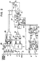
- comparators IC5 and IC6 are connected to a power supply through resistors R11 and R12, respectively and are also connected to the second input terminal of AND gate 53 through diodes D3 and D4.
- the ground fault sensor 27 When a ground fault of the motor driver 10 is detected by the ground fault sensor 27, the ground fault sensor 27 applies a high output signal to AND gate 29 or 30 after a prescribed delay which is produced by timer 34 or 35.
- comparator IC5 When the input voltage to the positive input terminal of comparator IC5 exceeds a reference voltage which is determined by resistors R9 and R10, the output of comparator IC5 goes high, and through diode D3, this output is input to AND gate 53.
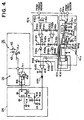
- comparator IC8 and the output terminal of comparator IC9 are connected to the positive input terminal of another comparator IC10 through diodes D42a and D42b, respectively, and are connected to ground through a resistor R42h.
- Capacitors C42b and C42c on the output sides of comparators IC8 and IC9 form the time limit circuit 42A.
- the output signals of comparators IC8 or IC9 In order for the input signal to the positive input terminal of comparator IC10 to go low, it is necessary for the output signals of comparators IC8 or IC9 to remain at low level for the discharge times of comparators C42b or C42c, respectively. This means that steering torque of at least a prescribed level must be applied for at least a prescribed length of time in order for the interrupter 25 to be activated.
Landscapes
- Engineering & Computer Science (AREA)
- Chemical & Material Sciences (AREA)
- Combustion & Propulsion (AREA)
- Transportation (AREA)
- Mechanical Engineering (AREA)
- Power Steering Mechanism (AREA)
- Steering Control In Accordance With Driving Conditions (AREA)
Claims (2)
- Elektrische Servolenkanlage für ein Fahrzeug, die folgendes aufweist:- einen Elektromotor (14), der an ein Lenkgetriebe eines Fahrzeugs angeschlossen werden kann, um das Fahrzeug zu lenken;- einen Lenkdrehmomentsensor (1), um das von einem Fahrer des Fahrzeugs auf eine Lenkwelle aufgebrachte Lenkdrehmoment zu messen und ein entsprechendes Ausgangssignal zu erzeugen;- eine Steuereinrichtung zum Bestimmen der richtigen Drehrichtung des Motors (14) auf der Basis des Ausgangssignals des Drehmomentsensors (1) und zur Erzeugung eines Antriebsrichtungssignals, das die Richtung angibt, in der sich der Motor (14) drehen soll;- einen Motortreiber (10), der auf die Steuereinrichtung (3) anspricht und den Motor (14) in der Richtung antreibt, die durch das Antriebsrichtungssignal angegeben ist;- eine Fahrzeuggeschwindigkeitspegel-Bestimmungseinrichtung (41A), die bestimmt, wenn die Geschwindigkeit des Fahrzeugs eine vorgeschriebene Geschwindigkeit überschreitet; und- eine Drehmomentpegel-Bestimmungseinrichtung (42A),dadurch gekennzeichnet,daß die Drehmomentpegel-Bestimmungseinrichtung (42A) bestimmt, wenn der Pegel des Lenkdrehmomentes, das von dem Fahrer des Fahrzeugs aufgebracht wird, ein vorgeschriebenes Drehmoment auf der Basis des Ausgangssignals vom Lenkdrehmomentsensor (1) überschreitet;daß die Anlage eine Zeitbegrenzungseinrichtung (43A) aufweist, um ein begrenztes Zeitintervall vorzugeben;und daß die Anlage ferner eine Unterbrechungseinrichtung (25) aufweist, die auf die Drehmomentpegel-Bestimmungseinrichtung (42A), die Fahrzeuggeschwindigkeitspegel-Bestimmungseinrichtung (41A) und die Zeitbegrenzungseinrichtung (43A) anspricht, um zu verhindern, daß Strom dem Motortortreiber (10) zugeführt wird, wenn die Geschwindigkeit des Fahrzeugs die vorgegebene Geschwindigkeit überschreitet und das von dem Fahrer aufgebrachte Drehmoment das vorgeschriebene Drehmoment zumindest für das Zeitintervall überschreitet.
- Servolenkanlage nach Anspruch 1,
dadurch gekennzeichnet,
daß die Zeitbegrenzungseinrichtung eine Einrichtung aufweist, um ein begrenztes Zeitintervall vorzugeben, das abnimmt, wenn die Geschwindigkeit des Fahrzeugs zunimmt.
Applications Claiming Priority (3)
| Application Number | Priority Date | Filing Date | Title |
|---|---|---|---|
| JP10813288A JPH07115643B2 (ja) | 1988-04-28 | 1988-04-28 | 電動式パワーステアリング装置 |
| JP108132/88 | 1988-04-28 | ||
| EP89304355A EP0340044B1 (de) | 1988-04-28 | 1989-04-28 | Elektrische Servolenkungseinrichtung |
Related Parent Applications (2)
| Application Number | Title | Priority Date | Filing Date |
|---|---|---|---|
| EP89304355.4 Division | 1989-04-28 | ||
| EP89304355A Division EP0340044B1 (de) | 1988-04-28 | 1989-04-28 | Elektrische Servolenkungseinrichtung |
Publications (2)
| Publication Number | Publication Date |
|---|---|
| EP0590697A1 EP0590697A1 (de) | 1994-04-06 |
| EP0590697B1 true EP0590697B1 (de) | 1997-01-15 |
Family
ID=14476744
Family Applications (2)
| Application Number | Title | Priority Date | Filing Date |
|---|---|---|---|
| EP89304355A Expired - Lifetime EP0340044B1 (de) | 1988-04-28 | 1989-04-28 | Elektrische Servolenkungseinrichtung |
| EP93119937A Expired - Lifetime EP0590697B1 (de) | 1988-04-28 | 1989-04-28 | Elektrische Servolenkeinrichtung |
Family Applications Before (1)
| Application Number | Title | Priority Date | Filing Date |
|---|---|---|---|
| EP89304355A Expired - Lifetime EP0340044B1 (de) | 1988-04-28 | 1989-04-28 | Elektrische Servolenkungseinrichtung |
Country Status (5)
| Country | Link |
|---|---|
| US (2) | US4957182A (de) |
| EP (2) | EP0340044B1 (de) |
| JP (1) | JPH07115643B2 (de) |
| KR (1) | KR920006532B1 (de) |
| DE (2) | DE68923122T2 (de) |
Cited By (1)
| Publication number | Priority date | Publication date | Assignee | Title |
|---|---|---|---|---|
| US6724286B2 (en) | 2000-02-29 | 2004-04-20 | General Electric Company | Adjustable trip solenoid |
Families Citing this family (38)
| Publication number | Priority date | Publication date | Assignee | Title |
|---|---|---|---|---|
| JPH0350074A (ja) * | 1989-04-22 | 1991-03-04 | Mitsubishi Electric Corp | モータ駆動式パワー・ステアリング装置 |
| EP0477820B1 (de) * | 1990-09-25 | 1995-12-20 | Mazda Motor Corporation | Hinterradlenkungsvorrichtung |
| FR2670735B1 (fr) * | 1990-12-19 | 1995-06-23 | Cartier Systemes | Mecanisme d'assistance temporaire pour colonne de direction de vehicules a roues directrices. |
| JPH05185938A (ja) * | 1991-09-30 | 1993-07-27 | Koyo Seiko Co Ltd | 電動パワーステアリング装置 |
| EP0522492B1 (de) * | 1991-07-10 | 1997-02-05 | Koyo Seiko Co., Ltd. | Lenkung mit elektrischer Hilfskraft |
| JP2643041B2 (ja) * | 1991-09-18 | 1997-08-20 | 三菱電機株式会社 | 電動パワーステアリング制御方法 |
| JPH0530485U (ja) * | 1991-09-28 | 1993-04-23 | 光洋精工株式会社 | ベーンポンプ |
| JP3131667B2 (ja) * | 1992-09-07 | 2001-02-05 | 光洋精工株式会社 | トルクセンサ |
| US5335979A (en) * | 1992-10-09 | 1994-08-09 | Mitsubishi Denki Kabushiki Kaisha | Control device for vehicle including anti-skid braking system and power steering control system |
| US6009364A (en) * | 1992-10-09 | 1999-12-28 | Mitsubishi Denki Kabushiki Kaisha | Power steering control apparatus for motor vehicle |
| US5485067A (en) * | 1993-07-02 | 1996-01-16 | Koyo Seiko Co., Ltd. | Electric power steering apparatus |
| JP2944867B2 (ja) * | 1993-10-26 | 1999-09-06 | 三菱電機株式会社 | 電動パワーステアリング制御装置 |
| JP2884315B2 (ja) * | 1993-11-19 | 1999-04-19 | 光洋精工株式会社 | 電動パワーステアリング装置 |
| JP3518944B2 (ja) * | 1996-04-11 | 2004-04-12 | 三菱電機株式会社 | モータ駆動装置 |
| US6131691A (en) * | 1996-09-13 | 2000-10-17 | Morch & Sonner A/S | System for guided steering of at least one set of wheels of a semi-trailer or a trailer |
| JP3554841B2 (ja) * | 1997-02-07 | 2004-08-18 | 光洋精工株式会社 | 自動車の舵取装置 |
| US6332506B1 (en) * | 1997-06-20 | 2001-12-25 | Mitsubishi Denki Kabushiki Kaisha | Motor driven power steering device |
| JP2998929B2 (ja) * | 1997-08-18 | 2000-01-17 | 本田技研工業株式会社 | 電動パワーステアリング装置 |
| JP3418098B2 (ja) * | 1997-08-27 | 2003-06-16 | 本田技研工業株式会社 | 電動パワーステアリング装置 |
| JP3639942B2 (ja) * | 1997-09-02 | 2005-04-20 | 光洋精工株式会社 | 電動パワーステアリング装置 |
| BR9804608A (pt) * | 1998-11-12 | 2000-10-24 | Brasil Compressores Sa | Sistema e método parta proteção de um motor elétrico e de seu circuito de contro0le e motor elétrico |
| JP4508320B2 (ja) * | 1999-10-01 | 2010-07-21 | 株式会社ミクニ | 電磁コイル動作装置の故障判別装置 |
| JP2001171539A (ja) * | 1999-12-16 | 2001-06-26 | Mitsubishi Electric Corp | 電動パワーステアリング装置 |
| US6392854B1 (en) * | 2000-07-27 | 2002-05-21 | Motorola, Inc. | Method and system for testing continuity of a motor and associated drive circuitry |
| US6731085B2 (en) | 2002-04-02 | 2004-05-04 | Trw Inc. | Method and apparatus for determining motor faults in an electric assist steering system |
| DE10223139A1 (de) * | 2002-05-24 | 2003-12-11 | Bosch Gmbh Robert | Elektronisch kommutierbarer Motor |
| JP4067389B2 (ja) * | 2002-11-14 | 2008-03-26 | 富士通テン株式会社 | タイヤロック判定方法 |
| KR100751244B1 (ko) * | 2003-04-21 | 2007-08-23 | 주식회사 만도 | 후륜 안정 보조장치 |
| US6879128B2 (en) * | 2003-07-28 | 2005-04-12 | Ims Inc. | Method and apparatus for independently controlling each phase of a multi-phase step motor |
| JP4539217B2 (ja) * | 2004-07-30 | 2010-09-08 | 日本精工株式会社 | 電動パワーステアリング装置 |
| KR101028724B1 (ko) * | 2004-10-11 | 2011-04-14 | 주식회사 만도 | 가변 랙 스트로크 시스템의 전자제어장치 |
| US7483796B2 (en) * | 2004-12-08 | 2009-01-27 | Trw Automotive U.S. Llc | Method and apparatus for determining faults in an electric assist steering system |
| US8498781B2 (en) * | 2007-01-05 | 2013-07-30 | Steven J. Collier-Hallman | Methods and motor computer program products for motor control by the implementation of damping for over-speed conditions |
| US7686109B2 (en) * | 2007-01-11 | 2010-03-30 | Glen Brazier | Motorized snowboard |
| DE102008021854A1 (de) * | 2008-05-02 | 2009-11-05 | Volkswagen Ag | Vorrichtung und Verfahren zur Überwachung möglicher Fehler in einer technischen Einrichtung, insbesondere Servo-Lenksystem |
| US8149551B2 (en) * | 2009-04-09 | 2012-04-03 | Hamilton Sundstrand Corporation | Systems and methods involving motor drive ground fault interrupts |
| JP5660997B2 (ja) * | 2011-08-08 | 2015-01-28 | オムロンオートモーティブエレクトロニクス株式会社 | 電動機制御装置 |
| JP5590077B2 (ja) * | 2012-07-04 | 2014-09-17 | 株式会社デンソー | 回転電機制御装置、および、これを用いた電動パワーステアリング装置 |
Family Cites Families (23)
| Publication number | Priority date | Publication date | Assignee | Title |
|---|---|---|---|---|
| CA933237A (en) * | 1971-06-16 | 1973-09-04 | A. I. Young John | Dc bus resistive path to ground fault detector |
| US4621327A (en) * | 1984-06-13 | 1986-11-04 | Nartron Corporation | Electronic power steering method and apparatus |
| JPS6150873A (ja) * | 1984-08-17 | 1986-03-13 | Jidosha Kiki Co Ltd | 電動式動力舵取装置 |
| US4573545A (en) * | 1984-08-30 | 1986-03-04 | Eaton Corporation | Fail-safe device for an electrical power assisted steering system including an in-line clutch mechanism |
| DE3435055A1 (de) * | 1984-09-25 | 1986-04-03 | Wabco Westinghouse Fahrzeugbremsen GmbH, 3000 Hannover | Einrichtung zum schutz einer blockierschutz-elektronik gegen ueberspannung |
| JP2515492B2 (ja) * | 1984-09-28 | 1996-07-10 | 光洋精工株式会社 | 操舵角センサの信号処理方法 |
| JPH07115642B2 (ja) * | 1985-07-09 | 1995-12-13 | 富士重工業株式会社 | 自動車用電動式パワステアリング装置の安全装置 |
| JPS6237274A (ja) * | 1985-08-09 | 1987-02-18 | Honda Motor Co Ltd | 電動式パワ−ステアリング装置 |
| JPH0798490B2 (ja) * | 1986-02-06 | 1995-10-25 | 本田技研工業株式会社 | 電動式パワーステアリング装置 |
| JPS62214055A (ja) * | 1986-03-13 | 1987-09-19 | Aisin Seiki Co Ltd | 電気式パワ−ステアリング装置 |
| JPS62221966A (ja) * | 1986-03-24 | 1987-09-30 | Honda Motor Co Ltd | 電動式パワ−ステアリング装置 |
| KR900008031B1 (ko) * | 1986-05-27 | 1990-10-31 | 미츠비시 덴키 가부시키가이샤 | 모터구동식 파워스테어링 제어장치 |
| JPS62283067A (ja) * | 1986-05-31 | 1987-12-08 | Aisin Seiki Co Ltd | 電動パワ−ステアリング装置 |
| JPS62292574A (ja) * | 1986-06-12 | 1987-12-19 | Mitsubishi Electric Corp | モ−タ駆動式パワ−ステアリング装置のフエ−ルセ−フ方法 |
| US4842087A (en) * | 1986-07-11 | 1989-06-27 | Mitsubishi Denki Kabushiki Kaisha | Motor driven type power steering control device |
| DE3723205A1 (de) * | 1986-07-19 | 1988-01-28 | Zahnradfabrik Friedrichshafen | Hilfskraftlenkung, insbesondere fuer kraftfahrzeuge |
| DE3624457A1 (de) * | 1986-07-19 | 1988-01-28 | Bayerische Motoren Werke Ag | Hinterradsteuerung von kraftfahrzeugen |
| JPH0624940B2 (ja) * | 1986-12-04 | 1994-04-06 | 三菱電機株式会社 | 電動式後輪操舵装置 |
| JPH069973B2 (ja) * | 1986-12-26 | 1994-02-09 | 日本精工株式会社 | モ−タ駆動式パワ−ステアリング制御装置 |
| GB2202501B (en) * | 1987-03-24 | 1991-08-21 | Honda Motor Co Ltd | Electric power steering system for vehicles |
| JPH0796388B2 (ja) * | 1987-04-13 | 1995-10-18 | 株式会社日立製作所 | 電動式パワ−ステアリング装置 |
| JPS63273038A (ja) * | 1987-05-01 | 1988-11-10 | Mazda Motor Corp | 車載制御機器の電源異常検出装置 |
| US4828060A (en) * | 1988-02-26 | 1989-05-09 | Trw Inc. | Auxiliary drive circuit for an electric assist steering system |
-
1988
- 1988-04-28 JP JP10813288A patent/JPH07115643B2/ja not_active Expired - Lifetime
-
1989
- 1989-03-22 KR KR1019890003574A patent/KR920006532B1/ko not_active Expired
- 1989-04-28 DE DE68923122T patent/DE68923122T2/de not_active Expired - Fee Related
- 1989-04-28 EP EP89304355A patent/EP0340044B1/de not_active Expired - Lifetime
- 1989-04-28 US US07/344,579 patent/US4957182A/en not_active Expired - Lifetime
- 1989-04-28 DE DE68927685T patent/DE68927685T2/de not_active Expired - Fee Related
- 1989-04-28 EP EP93119937A patent/EP0590697B1/de not_active Expired - Lifetime
-
1990
- 1990-06-04 US US07/532,407 patent/US4984647A/en not_active Expired - Lifetime
Cited By (1)
| Publication number | Priority date | Publication date | Assignee | Title |
|---|---|---|---|---|
| US6724286B2 (en) | 2000-02-29 | 2004-04-20 | General Electric Company | Adjustable trip solenoid |
Also Published As
| Publication number | Publication date |
|---|---|
| EP0340044A2 (de) | 1989-11-02 |
| US4984647A (en) | 1991-01-15 |
| DE68923122T2 (de) | 1996-02-01 |
| EP0340044A3 (de) | 1992-09-30 |
| US4957182A (en) | 1990-09-18 |
| EP0340044B1 (de) | 1995-06-21 |
| JPH01278878A (ja) | 1989-11-09 |
| DE68927685D1 (de) | 1997-02-27 |
| DE68923122D1 (de) | 1995-07-27 |
| KR890015926A (ko) | 1989-11-27 |
| KR920006532B1 (ko) | 1992-08-08 |
| JPH07115643B2 (ja) | 1995-12-13 |
| EP0590697A1 (de) | 1994-04-06 |
| DE68927685T2 (de) | 1997-09-11 |
Similar Documents
| Publication | Publication Date | Title |
|---|---|---|
| EP0590697B1 (de) | Elektrische Servolenkeinrichtung | |
| US5000278A (en) | Motorized power steering apparatus | |
| US4532567A (en) | Electric power steering stall protection circuit | |
| JP3460885B2 (ja) | 電動パワーステアリング制御装置 | |
| EP0304491B1 (de) | Motorbetriebene servolenkung für fahrzeuge | |
| JPS63255173A (ja) | 電動式パワ−ステアリング装置 | |
| JPH062467B2 (ja) | 電動式パワーステアリング装置 | |
| JP2602963B2 (ja) | モータ駆動式パワー・ステアリング装置 | |
| KR960005849B1 (ko) | 전동파워 스티어링 제어장치 및 방법 | |
| US5507359A (en) | Electrically operated power steering control device | |
| JPS62258862A (ja) | 電動パワ−ステアリング装置 | |
| EP0360474B1 (de) | Servomotorlenkeinrichtung | |
| JPH0787603A (ja) | 電気自動車の保護装置 | |
| JP2983714B2 (ja) | 電動パワステアリング制御装置 | |
| JPH0520976U (ja) | 電動パワーステアリング装置 | |
| JPH0455166A (ja) | 電動式パワーステアリング装置 | |
| EP0360470B1 (de) | Servomotorlenkeinrichtung | |
| EP0360469B1 (de) | Servomotorlenkeinrichtung | |
| JPH01285460A (ja) | 電動式パワーステアリング装置 | |
| JPH06127409A (ja) | 車両の後輪操舵装置 | |
| JPH05319296A (ja) | モータ駆動式パワーステアリング制御装置 | |
| JPH0621817Y2 (ja) | 動力舵取装置の電動ポンプ駆動制御装置 | |
| JP3055369B2 (ja) | 電動式パワーステアリング装置 | |
| JP3488988B2 (ja) | 電動パワーステアリング装置 | |
| JP2698913B2 (ja) | 電動式パワーステアリング装置の制御装置 |
Legal Events
| Date | Code | Title | Description |
|---|---|---|---|
| PUAI | Public reference made under article 153(3) epc to a published international application that has entered the european phase |
Free format text: ORIGINAL CODE: 0009012 |
|
| 17P | Request for examination filed |
Effective date: 19931230 |
|
| AC | Divisional application: reference to earlier application |
Ref document number: 340044 Country of ref document: EP |
|
| AK | Designated contracting states |
Kind code of ref document: A1 Designated state(s): DE FR GB |
|
| 17Q | First examination report despatched |
Effective date: 19951227 |
|
| GRAG | Despatch of communication of intention to grant |
Free format text: ORIGINAL CODE: EPIDOS AGRA |
|
| GRAH | Despatch of communication of intention to grant a patent |
Free format text: ORIGINAL CODE: EPIDOS IGRA |
|
| GRAH | Despatch of communication of intention to grant a patent |
Free format text: ORIGINAL CODE: EPIDOS IGRA |
|
| GRAA | (expected) grant |
Free format text: ORIGINAL CODE: 0009210 |
|
| AC | Divisional application: reference to earlier application |
Ref document number: 340044 Country of ref document: EP |
|
| AK | Designated contracting states |
Kind code of ref document: B1 Designated state(s): DE FR GB |
|
| REF | Corresponds to: |
Ref document number: 68927685 Country of ref document: DE Date of ref document: 19970227 |
|
| REG | Reference to a national code |
Ref country code: GB Ref legal event code: 727 |
|
| REG | Reference to a national code |
Ref country code: GB Ref legal event code: 727A |
|
| ET | Fr: translation filed | ||
| REG | Reference to a national code |
Ref country code: GB Ref legal event code: 727B |
|
| REG | Reference to a national code |
Ref country code: GB Ref legal event code: SP |
|
| PLBE | No opposition filed within time limit |
Free format text: ORIGINAL CODE: 0009261 |
|
| STAA | Information on the status of an ep patent application or granted ep patent |
Free format text: STATUS: NO OPPOSITION FILED WITHIN TIME LIMIT |
|
| 26N | No opposition filed | ||
| PGFP | Annual fee paid to national office [announced via postgrant information from national office to epo] |
Ref country code: FR Payment date: 20010409 Year of fee payment: 13 |
|
| PGFP | Annual fee paid to national office [announced via postgrant information from national office to epo] |
Ref country code: GB Payment date: 20010425 Year of fee payment: 13 |
|
| REG | Reference to a national code |
Ref country code: GB Ref legal event code: IF02 |
|
| PG25 | Lapsed in a contracting state [announced via postgrant information from national office to epo] |
Ref country code: GB Free format text: LAPSE BECAUSE OF NON-PAYMENT OF DUE FEES Effective date: 20020428 |
|
| GBPC | Gb: european patent ceased through non-payment of renewal fee |
Effective date: 20020428 |
|
| PG25 | Lapsed in a contracting state [announced via postgrant information from national office to epo] |
Ref country code: FR Free format text: LAPSE BECAUSE OF NON-PAYMENT OF DUE FEES Effective date: 20021231 |
|
| REG | Reference to a national code |
Ref country code: FR Ref legal event code: ST |
|
| PGFP | Annual fee paid to national office [announced via postgrant information from national office to epo] |
Ref country code: DE Payment date: 20060420 Year of fee payment: 18 |
|
| PG25 | Lapsed in a contracting state [announced via postgrant information from national office to epo] |
Ref country code: DE Free format text: LAPSE BECAUSE OF NON-PAYMENT OF DUE FEES Effective date: 20071101 |