EP0304491B1 - Motorbetriebene servolenkung für fahrzeuge - Google Patents
Motorbetriebene servolenkung für fahrzeuge Download PDFInfo
- Publication number
- EP0304491B1 EP0304491B1 EP88902238A EP88902238A EP0304491B1 EP 0304491 B1 EP0304491 B1 EP 0304491B1 EP 88902238 A EP88902238 A EP 88902238A EP 88902238 A EP88902238 A EP 88902238A EP 0304491 B1 EP0304491 B1 EP 0304491B1
- Authority
- EP
- European Patent Office
- Prior art keywords
- motor
- current
- power
- vehicle speed
- vehicle
- Prior art date
- Legal status (The legal status is an assumption and is not a legal conclusion. Google has not performed a legal analysis and makes no representation as to the accuracy of the status listed.)
- Expired - Lifetime
Links
Images


Classifications
-
- B—PERFORMING OPERATIONS; TRANSPORTING
- B62—LAND VEHICLES FOR TRAVELLING OTHERWISE THAN ON RAILS
- B62D—MOTOR VEHICLES; TRAILERS
- B62D5/00—Power-assisted or power-driven steering
- B62D5/04—Power-assisted or power-driven steering electrical, e.g. using an electric servo-motor connected to, or forming part of, the steering gear
- B62D5/043—Power-assisted or power-driven steering electrical, e.g. using an electric servo-motor connected to, or forming part of, the steering gear characterised by clutch means between driving element, e.g. motor, and driven element, e.g. steering column or steering gear
- B62D5/0433—Power-assisted or power-driven steering electrical, e.g. using an electric servo-motor connected to, or forming part of, the steering gear characterised by clutch means between driving element, e.g. motor, and driven element, e.g. steering column or steering gear the clutch being of on-off type
- B62D5/0436—Power-assisted or power-driven steering electrical, e.g. using an electric servo-motor connected to, or forming part of, the steering gear characterised by clutch means between driving element, e.g. motor, and driven element, e.g. steering column or steering gear the clutch being of on-off type the clutch being a controlled emergency clutch, e.g. for disconnecting at motor break-down
-
- B—PERFORMING OPERATIONS; TRANSPORTING
- B62—LAND VEHICLES FOR TRAVELLING OTHERWISE THAN ON RAILS
- B62D—MOTOR VEHICLES; TRAILERS
- B62D5/00—Power-assisted or power-driven steering
- B62D5/04—Power-assisted or power-driven steering electrical, e.g. using an electric servo-motor connected to, or forming part of, the steering gear
- B62D5/0457—Power-assisted or power-driven steering electrical, e.g. using an electric servo-motor connected to, or forming part of, the steering gear characterised by control features of the drive means as such
- B62D5/0481—Power-assisted or power-driven steering electrical, e.g. using an electric servo-motor connected to, or forming part of, the steering gear characterised by control features of the drive means as such monitoring the steering system, e.g. failures
- B62D5/0484—Power-assisted or power-driven steering electrical, e.g. using an electric servo-motor connected to, or forming part of, the steering gear characterised by control features of the drive means as such monitoring the steering system, e.g. failures for reaction to failures, e.g. limp home
-
- B—PERFORMING OPERATIONS; TRANSPORTING
- B62—LAND VEHICLES FOR TRAVELLING OTHERWISE THAN ON RAILS
- B62D—MOTOR VEHICLES; TRAILERS
- B62D5/00—Power-assisted or power-driven steering
- B62D5/04—Power-assisted or power-driven steering electrical, e.g. using an electric servo-motor connected to, or forming part of, the steering gear
- B62D5/0457—Power-assisted or power-driven steering electrical, e.g. using an electric servo-motor connected to, or forming part of, the steering gear characterised by control features of the drive means as such
- B62D5/0481—Power-assisted or power-driven steering electrical, e.g. using an electric servo-motor connected to, or forming part of, the steering gear characterised by control features of the drive means as such monitoring the steering system, e.g. failures
- B62D5/0487—Power-assisted or power-driven steering electrical, e.g. using an electric servo-motor connected to, or forming part of, the steering gear characterised by control features of the drive means as such monitoring the steering system, e.g. failures detecting motor faults
Definitions
- the present invention relates to a motor-driven power steering system for a vehicle and a method for controlling the same in which the operator-induced steering operation is power assisted by means of the rotative force of a motor.
- a conventional motor-driven power steering system in which a steering wheel is operatively connected through a steering shaft to a steering rack which is connected at its opposite ends with a pair of steerable road wheels so that when the steering wheel is turned by an operation, the steerable road wheels are appropriately steered in accordance with a steering force imparted to the steering wheel by the operator.
- the steering rack is operatively connected with a motor through a speed-reduction gear and an electromagnetic clutch so that the driving force of the motor is transmitted through the speed-reduction gear and the electromagnetic clutch to the steering rack so as to assist the operator-induced steering motion of the steering wheel.
- the motor is electrically connected with a battery through a control unit and a key or ignition switch so that it is energized by the battery under the control of the control unit.
- the control unit is input with control signals from a steering torque sensor and a vehicle-speed sensor so as to appropriately control the operations of the motor and the electromagnetic clutch on the basis of the steering torque and the vehicle speed measured.
- a power steering system of this nature is described for example in GB-A-2171657 ( ⁇ FR-A-2577878).
- a steering angle sensor is provided for sensing the steering angle of the front or steerable road wheels but even in this case, it is still difficult to precisely make such discrimination if an extraordinarily high steering torque is required when the steering wheel is located intermediate the righthand and lefthand limit positions. This will be caused, for example, when the front road wheels of the vehicle run onto a bump, a stone or a step on the road. In this case, it is erroneously judged that the high steering torque required, though due to large load on the front road wheels, would be caused by mechanical restriction resulting from a motor failure so that a failsafe mechanism is actuated to disconnect the electromagnetic clutch, thereby interrupting the assisting force from the motor.
- the present invention is intended to obviate the above-described problems of the prior art.
- An object of the present invention is to provide a motor-driven power steering system for a vehicle and a method for controlling the same in which it is possible to precisely judge whether or not there exists a failure in the operation of the motor with the clutch being disconnected so that an appropriate failsafe operation can be performed immediately upon a motor failure.
- a motor-driven power steering system for a vehicle having a steering wheel operatively connected with steerable road wheels so that the steering wheel is turned by an operator to appropriately steer said steerable road wheels
- said motor-driven power steering system comprising: a torque sensor for detecting steering torque imparted to said steering wheel by an operator to generate an output signal representative of the detected steering torque; a vehicle speed sensor for detecting the vehicle speed to generate an output signal representative of the detected vehicle speed; a motor connected to be energized by a source of electric power for power assisting the steering motion caused by the operator through said steering wheel; a clutch means interposed in a power transmission path through which power assisting force is transmitted from said motor to said steerable road wheels for controlling the transmission of the power assisting force, said clutch means being adapted to be switched on and off for selectively permitting and interrupting the transmission of the power-assisting force from said motor toward said steerable road wheels; and a control unit connected to receive output signals from said torque sensor and said vehicle speed sensor for controlling the operations of said
- a method for controlling a motor-driven power steering system for a vehicle in which a steering wheel is operatively connected with steerable road wheels so that it is turned by an operator to appropriately steer said steerable road wheels, and in which the steering motion imparted to said steering wheel by an operator can be power assisted by the assisting torque of a motor through a clutch means
- said method comprising steps of: measuring the travelling speed (V A ) of the vehicle; measuring the steering torque (T S ) imparted to said steering wheel by an operator; controlling the operations of said motor and said clutch means in such a manner that the power-assisting force transmitted from said motor to said steerable road wheels is adjusted in accordance with the vehicle speed and the steering torque; determining whether or not there exists a failure in operation of said motor; and controlling the clutch means in dependence on the existence of a motor failure; characterized by the steps of determining whether there exists a motor failure before said clutch means is connected; and controlling said clutch means and said motor (13) in such a manner that said clutch means
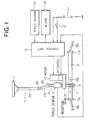
- a steering wheel 1 is operatively connected through a steering shaft 2 and a rack and pinion gear T including a pinion 5 and a rack tooth portion 6a with a steering rack 6 which is connected at its opposite ends with a pair of steerable road wheels (not shown) through a pair of tie rods 8a, 8b which are respectively coupled through ball joints 7a, 7b to the rack 6 so that when the steering wheel 1 is turned by an operator, the steerable road wheels (not shown) are appropriately steered in accordance with the steering motion of the steering wheel 1 imparted by the operator.
- the steering shaft 2 includes an upper shaft section 2a, an intermediate shaft section 2b and a lower shaft section 2c which are connected with each other through a first universal joint 4a and a second universal joint 4b, respectively.
- the lower shaft section 2c of the steering shaft 2 is operatively connected with a motor 13 in the form of a DC motor through a speed-reduction gear 15 and a clutch means 14 in the form of an electromagnetic clutch so that the driving force of the motor 13 is transmitted through the clutch means 14, the speed-reduction gear 15 and the rack and pinion gear T to the steering rack 6 so as to assist the steering operation of the steering wheel 1 imparted by the operator.
- the clutch means 14 is interposed between the motor 13 and the speed reduction gear 15 and acts to make and break the mechanical connection between the motor 13 and the speed-reduction gear 15.
- the motor 13 is electrically connected to a battery 11 through a control unit 9 and a key or ignition switch 12 so that it is energized by the battery 11 under the control of the control unit 9.
- An alarming means 16 in the form of a lamp, buzzer or the like is operatively associated with the control unit 9 for alarming a malfunction of the steering system.
- the control unit 9 is input with control signals from a steering torque sensor 3 and a vehicle speed sensor 10 so as to appropriately control the operations of the motor 13, the clutch means 14 and the alarming means 16 on the basis of the steering torque and the vehicle speed measured.
- the control unit 9 comprises a steering torque measuring means 9a which is connected to receive the output signal of the torque sensor 3 for measuring the operator-induced steering torque, a vehicle speed measuring means 9b which is connected to receive the output signal of the vehicle speed sensor 10 for measuring the travelling speed of the vehicle, a motor current storing means 9c which stores motor current values corresponding to varying vehicle speeds and varying steering torque values as well as comparison values such as a reference current value I MB and reference vehicle speed values V 1 - V 3 and the like, a motor current determining means 9d which is connected to receive the output signals from the steering torque measuring means 9a and the vehicle speed measuring means 9b, and which operates to read out from the motor current storing means 9c appropriate comparison values and compare them with the measured motor current and the measured vehicle speed so as to determine an appropriate current value to be supplied to the motor 13 which corresponds to the measured vehicle speed and the measured steering torque, a motor current controlling means 9e for controlling the current supplied to the electromagnetic clutch 14 in accordance with the output from the motor-
- Step S1 When the key or ignition switch 12 is first turned on to start the engine, current is supplied to the control unit 9 from the power source 11 to initialize the control unit 9 in Step S1. Then in Step S2, the vehicle speed measuring means 9b measures the vehicle speed V A from the output signal of the speed sensor 10, and in Step S3, the steering torque measuring means 9a measures from the output signal of the torque sensor 3 the steering torque T S which is imparted to the steering wheel 1 by the operator.
- Step S4 the motor current determining means 9d first compares the vehicle speed V A thus measured in Step S2 with the previously measured vehicle speed read out from the motor current storing means 9c or with the vehicle speed at which the control unit 9 is initialized, and then judges from the result of this comparison whether or not the vehicle speed is decreasing. If it is judged "YES” (i.e, the vehicle speed is decreasing), the control process proceeds to Step S5, but if "NO” (i.e., the vehicle speed is increasing), the control process proceeds to Step S8.
- Step S5 it is judged whether or not the vehicle speed V A is greater than a first predetermined reference level V 3 which corresponds to point g in Fig. 5 which represents a clutch checking speed during high-speed travel. If V A ⁇ V 3 , the judgement in Step S5 becomes “YES” and the control process proceeds to Step S6, but if it is judged "NO” (i.e., V A ⁇ V 3 ), the control process proceeds to Step S12. In this connection, if the judgement in Step S5 is "YES", it is determined that the vehicle is being steered, and hence the motor current controlling means 9e reduces the current to be supplied to the motor 13 to zero in Step S6. Then, the control process proceeds to Step S7 wherein the clutch condition judging means 9f disconnects the electromagnetic clutch 14 through the clutch ontrolling means 9g. Thereafter, the control process returns from Step S7 to Step S2.
- Step S4 determines whether or not the vehicle speed V A is greater than a second predetermined reference level V 1 which corresponds to point f in Fig. 5 representative of a power-assist interruption speed which is less than the clutch checking speed V 3 .
- Step S6 If it is "YES” (i.e., V A > V 1 ), it is determined that the vehicle is being steered and the control process proceeds to Step S6, but if "NO” (i.e., V 1 ⁇ V A ), the control process proceeds to Step S9 wherein it is further judged whether or not the vehicle speed V A is greater than a third predetermined reference level V 2 which corresponds to point e in Fig. 5 representative of a power-assist decreasing speed which is less than the power-assist interruption speed V 1 .
- Step S9 if it is "YES" (i.e., V A ⁇ V 2 ), the control process proceeds to Step S10 wherein the motor current determining means 9d reads out from the motor current storing means 9c a motor current value I OF , which corresponds to the vehicle speed V A and the steering torque T S , so as to determine an appropriate motor current I MT . Then in Step S11, the motor current controlling means 9e controls the current I M to be supplied to the motor 13 to be I MT which is equal to I OF , and thereafter the control process returns to Step S2.
- the motor current determining means 9d reads out from the motor current storing means 9c a motor current value I OF , which corresponds to the vehicle speed V A and the steering torque T S , so as to determine an appropriate motor current I MT .
- the motor current controlling means 9e controls the current I M to be supplied to the motor 13 to be I MT which is equal to I OF , and thereafter the control process returns to Step S2.
- Step S9 if it is judged "NO” (i.e., V 2 ⁇ V A ) in Step S9, or if it is judged "NO” (i.e., V 3 ⁇ V A ) in Step S5, it is further judged in Step S12 whether or not the connection of the clutch 14 is effected for the first time. If it is not the first time but second or more time, then in Step S13, the motor current determining means 9d reads out an appropriate motor current value I MI corresponding to the vehicle speed V A and the steering torque T S as in Step S10. Thereafter in Step S14, the motor current controlling means 9e controls the current I M to be supplied to the motor 13 to be I MI and then the control process returns to Step S2.
- Step S12 If it is judged to be "for the first time” in Step S12, the control process proceeds to Step S15 wherein the clutch condition judging means 9f judges whether or not the electromagnetic clutch 14 has been already connected. If it is "YES”, the control process returns to Step S2 whereas if "NO”, the process proceeds to Step S16.
- Step S16 the motor current controlling means 9e acts to energize the motor 13, and the clutch condition judging means 9f measures the motor current I MA .
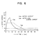
- the clutch condition judging means 9f judges whether or not the motor current I MA is greater than a reference level, I MB which is set as a motor-load judging current as shown in Fig. 6. If it is judged "NO" (i.e., I MB ⁇ I MA ,) in Step S17, it is determined that both the motor 13 and the electromagnetic clutch 14 are in normal operation, and that the motor 13 is not subjected to any mechanical restriction and operates normally.
- the clutch controlling means 9g receives the output signal from the clutch condition judging means 9f and switches on or connects the electromagnetic clutch 14.
- Step S17 if it is judged "YES" (i.e., I MA ⁇ I MB ) in Step S17, it is considered that the motor 13 may be mechanically restricted. Thus, in this case, the control process proceeds to Step S19 wherein it is judged whether or not the length of a judging period T, which is the time duration from the start-up time of the motor to the time when the motor-load judging current I MB is measured as illustrated in Fig. 6, is greater than a reference time T M which is a predetermined motor-load judging period.
- Step S19 if the clutch condition judging means 9f judges that the judging period T is greater than the motor-load judging period T M (i.e., T ⁇ T M ), it is determined that the motor 13 and/or the clutch 14 is in failure, and that the motor 13 is mechanically restricted. In this case, the control process proceeds to Step S20 wherein the motor current controlling means 9e reduces the current I M to be supplied to the motor 13 to zero. Then in Step S21, the control unit 9 operates to perform a predetermined failsafe processing such as alarming the operator of the mechanical restriction of the motor 13, for example, by actuating the alarming means 16.
- a predetermined failsafe processing such as alarming the operator of the mechanical restriction of the motor 13, for example, by actuating the alarming means 16.
- Steps S4, S5, S8 and S9 are effected by the motor current determining means 9d by making appropriate comparison with appropriate comparison values read out from the motor current storing means 9c.
- Step S12 it is judged whether connection of the clutch 14 is effected for the first time or not, it may of course be judged whether such connection is effected at the n-th time (n ⁇ 2), i.e., at the second or certain predetermined time.
- a judgement in Step S12 can be carried out by the motor current determining means 9d or the clutch condition judging means 9f.
- the motor current I MA thus measured reduces below the motor-load judging current value I MB , which is for example 5 to 10 amperes, in a certain period of time, it is judged that both the motor 13 and the clutch 14 operate normally, and motor 13 is energized to rotate and the clutch 14 is also energized or switched on to make mechanical connection between the motor 13 and the speed-reduction gear 15 for transmission of power-assisting force from the motor 13 to the steering rack 6.
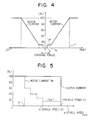
- control unit 9 acts to control the current to be supplied to the motor 13 in the manner as illustrated in Fig. 4.
- the motor 13 is turned on and supplied with an offset current of a certain low level I OF (for example, about 2 to 10 amperes) in order to alleviate the inertia influence from the motor 13 and the related mechanical portions.
- I OF a certain low level
- the current supplied to the motor 13 begins to increase, at point b , linearly in direct proportion to the intensity of steering torque, and reaches 100 % current at point c .
- current flowing through the motor 13 begins to decrease at point c and becomes to be the offset level I OF at point b .
- the current supply to the motor 13 is reduced to zero and the motor 13 is stopped. Similar to this, the motor 13 is controlled in the same manner when the steering torque increases or decreases in the counterclockwise or lefthand direction. In this connection, it is to be noted that the power-assisting torque generated by the motor 13 is in direct proportion to the current supplied thereto.
- the motor 13 is energized or turned on at point a and supplied with the offset current I OF .
- the current supplied to the motor 13 is gradually increased at point b so that the output torque of the motor 13 accordingly increases gradually.
- the assisting torque having the intensity corresponding to the operator's steering effort applied to the steering wheel 1 is transmitted to the rack tooth portion 6a on the steering rack 6 through the intermediary of the electromagnetic clutch 14 and the speed-reduction gear 15, thereby lightening the steering operation for the operator.
- the control unit 9 controls the operation of the motor 13 in such a manner that the current supplied to the motor 13 is controlled on the basis of the steering torque imparted to the steering wheel 1 by the operator and the travelling speed of the vehicle.
- the motor current is controlled to change stepwise. More specifically, as illustrated in Fig. 5, the amount of current I M supplied to the motor 13 is set to be 100 % until the vehicle speed V A increases above a certain level at point d , and it is decreased in a stepwise fashion as the vehicle speed V A further increases from point d .
- the motor current I M is held constant at the offset level I OF in order to alleviate the inertia influence from the mechanical portions of the power steering system. Then, at the time when the vehicle speed V A increases and reaches the power-assist interruption speed V 1 at point f , the current supplied to the motor 13 is made to be zero, and at the same time the electromagnetic clutch 14 is also deenergized or disconnected so that the mechanical connection between the motor 13 and the speed-reduction gear 15 is broken, thus rendering the steering system into a non-power assisted manual steering mode.
- the motor 13 is caused to make a trial run. If the motor current I MA decreases below the motor-load judging current value I MB after the motor-load determining period T M during the start-up of the motor 13, the control unit 9 permits the electromagnetic clutch 14 to be connected, and then switches on the clutch 14 when the vehicle speed V A decreases to reach the power-assist interruption speed V 1 at point f .
- the control unit 9 judging that the motor 13 is in failure, operates to interrupt power supply to the motor 13 and keep the electromagnetic clutch 14 switched off for failsafe purposes, and actuate the alarming means 16 so as to warn the operator of such a failure.
- the motor is first energized to make a trial run for measuring the time-related motor-current characteristic before the clutch means is switched on to connect, and the measured value of motor current is compared with appropriate preset reference values so as to judge whether there exists abnormality or failure in operation of the motor. If the motor is judged to be in failure, the clutch means is kept disconnected. Thus, abnormality or failure of the motor can be detected before connection of the clutch means so that failsafe operation can be carried out immediately. Further, it is possible to judge such a motor fialure independently of load conditions of the motor and hence there will be substantially no misjudgement as encountered with the prior art system, thereby providing a motor-driven steering system with a high degree of safety.
Landscapes
- Engineering & Computer Science (AREA)
- Chemical & Material Sciences (AREA)
- Combustion & Propulsion (AREA)
- Transportation (AREA)
- Mechanical Engineering (AREA)
- Power Steering Mechanism (AREA)
- Steering Control In Accordance With Driving Conditions (AREA)
Claims (18)
- Motorgetriebenes Servolenksystem für ein Fahrzeug mit einem Lenkrad (1), das mit lenkbaren Laufrädern betriebsmäßig so verbunden ist, daß das Lenkrad von einem Fahrer eingeschlagen wird, um die lenkbaren Laufräder in geeigneter Weise zu lenken, wobei das motorgetriebene Servolenksystem folgendes aufweist:- einen Drehmomentsensor (3), um ein von einem Fahrer auf das Lenkrad aufgebrachtes Lenkdrehmoment zu erfassen, um ein Ausgangssignal zu erzeugen, das das erfaßte Lenkdrehmoment bezeichnet;- einen Fahrzeuggeschwindigkeitssensor (10), um die Fahrzeuggeschwindigkeit zu erfassen, um ein Ausgangssignal zu erzeugen, das die erfaßte Fahrzeuggeschwindigkeit bezeichnet;- einen Motor (13), der angeschlossen ist, um von einer elektrischen Stromquelle aktiviert zu werden, um die Lenkbewegung, die von dem Fahrer durch das Lenkrad bewirkt wird, durch eine Hilfskraft zu unterstützen;- eine Kupplungseinrichtung (14), die in einen Kraftübertragungsweg eingefügt ist, durch den Hilfskraft von dem Motor (13) zu den lenkbaren Laufrädern übertragen wird, um die Übertragung der Hilfskraft zu steuern, wobei die Kupplungseinrichtung (14) ein- und ausschaltbar ist, um die Übertragung der Hilfskraft von dem Motor zu den lenkbaren Laufrädern selektiv zuzulassen und zu unterbrechen; und- eine Steuereinheit (9), die angeschlossen ist, um von dem Drehmomentsensor (3) und dem Fahrzeuggeschwindigkeitssensor (10) Ausgangssignale zu empfangen, um den Betrieb des Motors (13) und der Kupplungseinrichtung (14) in solcher Weise zu steuern, daß die Hilfskraft, die von dem Motor zu den lenkbaren Laufrädern übertragen wird, nach Maßgabe der Fahrzeuggeschwindigkeit und des Lenkdrehmoments eingestellt wird, dadurch gekennzeichnet, daß die Steuereinheit (9) betätigbar ist, um einen Motorstromkennwert (IMA) während einer Anlaufperiode des Motors (13), bevor die Kupplungseinrichtung (14) angeschlossen ist, zu messen, um den so gemessenen Motorstromkennwert mit einem Motorlast-Beurteilungsstrom (IMB) zu vergleichen, um zu beurteilen, daß eine Störung in dem Motor vorliegt, wenn der gemessene Anlaufmotorstrom nach einer vorbestimmten Zeitperiode (TM) seit dem Einschalten des Motors größer als der Motorlast-Beurteilungsstrom ist, und um die Kupplungseinrichtung (14) und den Motor (13) in solcher Weise zu steuern, daß ein Anschließen der Kupplungseinrichtung zugelassen wird, wenn keine Störung vorliegt, wohingegen die Kupplungseinrichtung getrennt gehalten wird, so daß ein angemessener ausfallsicherer Betrieb erfolgen kann, wenn eine derartige Störung vorliegt.
- Motorgetriebenes Servolenksystem für ein Fahrzeug nach Anspruch 1, das ferner eine Alarmeinrichtung aufweist, die angeschlossen ist, um von der Steuereinheit betätigt zu werden, um den Fahrer auf eine Störung des Motors aufmerksam zu machen, wenn die Steuereinheit beurteilt, daß eine derartige Störung vorliegt.
- Motorgetriebenes Servolenksystem für ein Fahrzeug nach Anspruch 1, wobei die Steuereinheit folgendes aufweist:- eine Lenkdrehmoment-Meßeinrichtung (9a), die angeschlossen ist, um das Ausgangssignal des Drehmomentsensors (3) zu empfangen, um das vom Fahrer induzierte Lenkdrehmoment zu messen;- eine Fahrzeuggeschwindigkeits-Meßeinrichtung (9b), die angeschlossen ist, um das Ausgangssignal des Fahrzeuggeschwindigkeitssensors (10) zu empfangen, um die Fahrgeschwindigkeit des Fahrzeugs zu messen;- eine Motorstrom-Speichereinrichtung (9c), die Motorstromwerte, die sich ändernden Fahrzeuggeschwindigkeiten und sich ändernden Lenkdrehmomentwerten entsprechen, sowie Vergleichswerte speichert, die einen Bezugsstromwert und Bezugsfahrzeuggeschwindigkeitswerte umfassen;- eine Motorstrom-Bestimmungseinrichtung (9d), die angeschlossen ist, um die Ausgangssignale der Lenkdrehmoment-Meßeinrichtung (3) und der Fahrzeuggeschwindigkeits-Meßeinrichtung (10) zu empfangen, und die die Funktion hat, aus der Motorstrom-Speichereinrichtung (9c) geeignete Bezugswerte auszulesen und den gemessenen Motorstrom und die gemessene Fahrzeuggeschwindigkeit mit den so ausgelesenen geeigneten Bezugswerten zu vergleichen, um einen geeigneten Motorstrom zu bestimmen, der der gemessenen Fahrzeuggeschwindigkeit und dem gemessenen Lenkdrehmoment entspricht;- eine Motorstrom-Steuereinrichtung (9e), die den Strom, der dem Motor (13) zuzuführen ist, nach Maßgabe des Ausgangssignals der Motorstrom-Bestimmungseinrichtung (9d) steuert; und- eine Kupplungszustands-Beurteilungseinrichtung (9f), die aufgrund der Vergleichsergebnisse beurteilt, ob der Motor (13) mechanisch gehemmt ist, und die die Funktion hat, ein Anschließen der Kupplungseinrichtung (14) zuzulassen, wenn beurteilt wird, daß der Motor nicht mechanisch gehemmt ist, die Kupplungseinrichtung jedoch getrennt hält, wenn beurteilt wird, daß der Motor mechanisch gehemmt ist; und- eine Kupplungssteuereinrichtung (9g), die die Funktion hat, die Kupplungseinrichtung (14) aufgrund des Ausgangssignals der Kupplungszustands-Beurteilungseinrichtung (9f) selektiv anzuschließen und zu trennen.
- Motorgetriebenes Servolenksystem für ein Fahrzeug nach Anspruch 3, wobei die Motorstrom-Bestimmungseinrichtung (9d) aus der Motorstrom-Speichereinrichtung (9c) einen Motorlast-Beurteilungsstrom (IMI), eine Hilfskraft-Unterbrechungsgeschwindigkeit (V1) und eine Hilfskraft-Verringerungsgeschwindigkeit (V2) ausliest, die niedriger als die Hilfskraft-Unterbrechungsgeschwindigkeit ist, und die gemessene Fahrzeuggeschwindigkeit (VA) und den gemessenen Motorstrom (IMA) mit ihnen vergleicht und den Betrieb des Motors (13) und der Kupplungseinrichtung (14) in solcher Weise steuert, daß der Strom, der dem Motor zuzuführen ist, zu Null gemacht wird, wenn die Fahrzeuggeschwindigkeit gleich der oder niedriger als die Hilfskraft-Verringerungsgeschwindigkeit zu einem vorgegebenen Zeitpunkt ist und wenn der gemessene Motorstrom länger als eine vorbestimmte Zeitdauer größer als der Motorlast-Beurteilungsstrom ist, wobei die Kupplungseinrichtung während des Anlaufens des Motors getrennt ist.
- Motorgetriebenes Servolenksystem für ein Fahrzeug nach Anspruch 4, wobei die Motorstrom-Bestimmungseinrichtung (9d) eine Ausfallsicherheitsverarbeitung vornimmt, nachdem der Strom, der dem Motor zuzuführen ist, zu Null gemacht ist.
- Motorgetriebenes Servolenksystem für ein Fahrzeug nach Anspruch 4 oder 5, wobei die Motorstrom-Bestimmungseinrichtung (9d) die Kupplungseinrichtung (14) anschließt, wenn die Fahrzeuggeschwindigkeit (VA) gleich der oder niedriger als die Hilfskraft-Verringerungsgeschwindigkeit (V2) zu dem vorgegebenen Zeitpunkt ist und wenn der gemessene Motorstrom (IMA) gleich dem oder niedriger als der Motorlast-Beurteilungsstrom (IMB) ist.
- Motorgetriebenes Servolenksystem für ein Fahrzeug nach Anspruch 6, wobei die Motorstrom-Bestimmungseinrichtung (9d) den Motor (13) in solcher Weise steuert, daß der Strom, der dem Motor zuzuführen ist, aufgrund der gemessenen Fahrzeuggeschwindigkeit (VA) und des gemessenen Lenkdrehmoments (TS) bestimmt wird, wenn die Fahrzeuggeschwindigkeit gleich der oder niedriger als die Hilfskraft-Verringerungsgeschwindigkeit (V2) ist, jedoch nicht zu einem bestimmten vorgegebenen Zeitpunkt.
- Motorgetriebenes Servolenksystem für ein Fahrzeug nach Anspruch 6 oder 7, wobei die Motorstrom-Bestimmungseinrichtung (9d) den Motor (13) in solcher Weise steuert, daß der Strom, der dem Motor zuzuführen ist, auf einen Offset-Pegel gelegt wird, wenn die Fahrzeuggeschwindigkeit gleich der oder niedriger als die Hilfskraft-Unterbrechungsgeschwindigkeit (V1), aber höher als die Hilfskraft-Verringerungsgeschwindigkeit (V2) ist.
- Verfahren zum Regeln eines motorgetriebenen Servolenksystems für ein Fahrzeug, bei dem das Lenkrad (1) mit lenkbaren Laufrädern betriebsmäßig so verbunden ist, daß es von einem Fahrer eingeschlagen wird, um die lenkbaren Laufräder in geeigneter Weise zu lenken, und bei dem die Lenkbewegung, die von einem Fahrer auf das Lenkrad aufgebracht wird, von dem unterstützenden Drehmoment eines Motors (13) über eine Kupplungseinrichtung (14) durch eine Hilfskraft unterstützt werden kann, wobei das Verfahren folgende Schritte aufweist:- Messen der Fahrgeschwindigkeit (VA) des Fahrzeugs;- Messen des Lenkdrehmoments (TS), das von einem Fahrer auf das Lenkrad aufgebracht wird;- Steuern des Betriebs des Motors (13) und der Kupplungseinrichtung (14) in solcher Weise, daß die Hilfskraft, die von dem Motor zu den lenkbaren Laufrädern übertragen wird, nach Maßgabe der Fahrzeuggeschwindigkeit und des Lenkdrehmoments eingestellt wird;- Bestimmen, ob eine Störung im Betrieb des Motors vorliegt; und- Steuern der Kupplungseinrichtung in Abhängigkeit von dem Vorliegen einer Motorstörung;
gekennzeichnet durch folgende Schritte:- Bestimmen, ob eine Motorstörung vorliegt, bevor die Kupplungseinrichtung (14) angeschlossen wird; und- Steuern der Kupplungseinrichtung (14) und des Motors (13) in solcher Weise, daß ein Anschließen der Kupplungseinrichtung zugelassen wird, wenn keine Störung vorliegt, wohingegen die Kupplungseinrichtung getrennt gehalten wird, so daß ein angemessener ausfallsicherer Betrieb erfolgen kann, wenn eine derartige Störung vorliegt. - Verfahren nach Anspruch 9, wobei der Schritt des Bestimmens, ob eine Störung im Betrieb des Motors und der Kupplungseinrichtung vorliegt, folgende Schritte aufweist:- Messen eines bestimmten Kennwerts (IMA) des Motors, bevor die Kupplungseinrichtung angeschlossen wird; und- Vergleichen des so gemessenen Kennwerts mit einem vorbestimmten Bezugswert (IMB) des Motors, bevor die Kupplungseinrichtung angeschlossen wird; und- Vergleichen des so gemessenen Kennwerts mit einem vorbestimmten Bezugswert (IMB).
- Verfahren zum Steuern eines motorgetriebenen Servolenksystems für ein Fahrzeug nach Anspruch 10, wobei der Kennwert des Motors ein Motorstromkennwert während einer Anlaufperiode des Motors ist und der vorbestimmte Bezugswert ein Motorlast-Beurteilungsstrom ist, wobei das Verfahren ferner folgende Schritte aufweist:- Vergleichen des während des Anlaufens des Motors gemessenen Motorstroms (IMA) mit dem Motorlast-Beurteilungsstrom (IMB); und- Beurteilen, daß eine Störung in dem Motor vorliegt, wenn der Anlaufmotorstrom nach einer vorbestimmten Zeitperiode seit dem Einschalten des Motors größer als der Motorlast-Beurteilungsstrom ist.
- Verfahren nach Anspruch 9, 10 oder 11, das ferner folgende Schritte aufweist:- Speichern von Motorstromwerten (IMI), die sich ändernden Fahrzeuggeschwindigkeiten und sich ändernden Lenkdrehmomentwerten entsprechen, sowie von Vergleichswerten, die einen Bezugsstromwert und Bezugsfahrzeugge-schwindigkeitsswerte umfassen;- Auslesen geeigneter Bezugswerte aus den gespeicherten Vergleichswerten;- Vergleichen des gemessenen Motorstroms (IMA) und der gemessenen Fahrzeuggeschwindigkeit (VA) mit den so ausgelesenen geeigneten Bezugswerten; und- Beurteilen aufgrund der Vergleichsergebnisse, ob der Motor mechanisch gehemmt ist, so daß ein Anschließen der Kupplungseinrichtung zugelassen wird, wenn beurteilt wird, daß der Motor nicht mechanisch gehemmt ist, die Kupplungseinrichtung jedoch getrennt gehalten wird, wenn beurteilt wird, daß der Motor mechanisch gehemmt ist.
- Verfahren nach Anspruch 12, wobei in dem Ausleseschritt ein Motorlast-Beurteilungsstrom (IMB), eine Hilfskraft-Unterbrechungsgeschwindigkeit (V1) und eine Hilfskraft-Verringerungsgeschwindigkeit (V2), die niedriger als die Hilfskraft-Unterbrechungsgeschwindigkeit ist, als Bezugswerte ausgelesen werden und in dem Vergleichsschritt die gemessene Fahrzeuggeschwindigkeit (VA) und der gemessene Motorstrom (IMA) mit so ausgelesenen Bezugswerten verglichen werden, um den Motor (13) und die Kupplungseinrichtung (14) in solcher Weise zu steuern, daß der Strom, der dem Motor zuzuführen ist, zu Null gemacht wird, wenn die Fahrzeuggeschwindigkeit gleich der oder niedriger als die Hilfskraft-Verringerungsgeschwindigkeit (V2) zu einem vorgegebenen Zeitpunkt ist und wenn der gemessene Motorstrom länger als eine vorbestimmte Zeitdauer größer als der Motorlast-Beurteilungsstrom (IMB) ist, wobei die Kupplungseinrichtung während des Anlaufens des Motors getrennt ist.
- Verfahren nach Anspruch 13, wobei die Kupplungseinrichtung angeschlossen wird, wenn die Fahrzeuggeschwindigkeit gleich oder niedriger als die Hilfskraft-Verringerungsgeschwindigkeit (V2) zu dem vorgegebenen Zeitpunkt ist und wenn der gemessene Motorstrom gleich dem oder niedriger als der Motorlast-Beurteilungsstrom (IMB) ist.
- Verfahren nach Anspruch 13 oder 14, wobei der Strom, der dem Motor (13) zuzuführen ist, aufgrund der gemessenen Fahrzeuggeschwindigkeit und des gemessenen Lenkdrehmoments bestimmt wird, wenn die Fahrzeuggeschwindigkeit gleich der oder niedriger als die Hilfskraft-Verringerungsgeschwindigkeit (V2) ist, jedoch nicht zu einem bestimmten vorgegebenen Zeitpunkt.
- Verfahren nach Anspruch 15, wobei der Strom, der dem Motor zuzuführen ist, auf einen Offsetpegel gelegt wird, wenn die Fahrzeuggeschwindigkeit gleich der oder niedriger als die Hilfskraft-Unterbrechungsgeschwindigkeit (V1), aber höher als die Hilfskraft-Verringerungsgeschwindigkeit (V2) ist.
- Verfahren nach einem der Ansprüche 9 bis 16, das ferner die Durchführung einer Ausfallsicherheitsverarbeitung aufweist, nachdem der Strom, der dem Motor zuzuführen ist, zu Null gemacht worden ist.
- Verfahren nach einem der Ansprüche 9 bis 17, das ferner das Aufmerksammachen des Fahrers auf eine Störung des Motors aufweist, wenn beurteilt wird, daß eine derartige Störung vorliegt.
Applications Claiming Priority (2)
| Application Number | Priority Date | Filing Date | Title |
|---|---|---|---|
| JP49678/87 | 1987-03-04 | ||
| JP4967887A JPH06506B2 (ja) | 1987-03-04 | 1987-03-04 | モ−タ駆動式パワ−ステアリング制御方法 |
Publications (2)
| Publication Number | Publication Date |
|---|---|
| EP0304491A1 EP0304491A1 (de) | 1989-03-01 |
| EP0304491B1 true EP0304491B1 (de) | 1992-10-07 |
Family
ID=12837833
Family Applications (1)
| Application Number | Title | Priority Date | Filing Date |
|---|---|---|---|
| EP88902238A Expired - Lifetime EP0304491B1 (de) | 1987-03-04 | 1988-03-04 | Motorbetriebene servolenkung für fahrzeuge |
Country Status (6)
| Country | Link |
|---|---|
| US (1) | US5999870A (de) |
| EP (1) | EP0304491B1 (de) |
| JP (1) | JPH06506B2 (de) |
| KR (1) | KR890700506A (de) |
| DE (1) | DE3875196T2 (de) |
| WO (1) | WO1988006546A1 (de) |
Families Citing this family (23)
| Publication number | Priority date | Publication date | Assignee | Title |
|---|---|---|---|---|
| JPH01223071A (ja) * | 1988-02-29 | 1989-09-06 | Aisin Seiki Co Ltd | 電動式パワーステアリング装置 |
| JP2679803B2 (ja) * | 1988-04-08 | 1997-11-19 | マツダ株式会社 | 車両の後輪操舵装置 |
| US5274555A (en) * | 1990-08-10 | 1993-12-28 | Matsushita Electric Industrial Co., Ltd. | Controlling apparatus of steering angle of rear wheels of four-wheel steering vehicle |
| JP2643041B2 (ja) * | 1991-09-18 | 1997-08-20 | 三菱電機株式会社 | 電動パワーステアリング制御方法 |
| JP2815763B2 (ja) * | 1992-08-17 | 1998-10-27 | スズキ株式会社 | 電動パワーステアリング制御装置及び方法 |
| JP2944867B2 (ja) * | 1993-10-26 | 1999-09-06 | 三菱電機株式会社 | 電動パワーステアリング制御装置 |
| JP3462007B2 (ja) * | 1996-06-10 | 2003-11-05 | 三菱電機株式会社 | 直流モータの回転角および負荷トルク検出方法、直流モータ制御装置および電動式パワーステアリング装置 |
| DE19633632A1 (de) * | 1996-08-21 | 1998-02-26 | Zahnradfabrik Friedrichshafen | Steuergerät für eine Hilfskraftlenkung für Kraftfahrzeuge |
| JP2000198456A (ja) * | 1998-12-28 | 2000-07-18 | Honda Motor Co Ltd | 電動パワ―ステアリング装置 |
| US6456946B1 (en) * | 2000-02-25 | 2002-09-24 | Motorola, Inc. | System and method for motor fault detection |
| US6834261B1 (en) | 2000-10-27 | 2004-12-21 | Visteon Corporation | Simulated steering feel system |
| JP3868263B2 (ja) * | 2001-10-29 | 2007-01-17 | 株式会社ジェイテクト | パワーステアリング装置 |
| US6666294B2 (en) * | 2002-01-10 | 2003-12-23 | Dayco Products, Llc | Belt driven mechanical boost power steering |
| JP4675886B2 (ja) * | 2004-04-30 | 2011-04-27 | 日本精工株式会社 | 電動パワーステアリング装置の制御装置 |
| JP4608948B2 (ja) * | 2004-05-27 | 2011-01-12 | 日産自動車株式会社 | 車両用操舵装置 |
| JP5093552B2 (ja) * | 2006-05-09 | 2012-12-12 | 株式会社ジェイテクト | 車両用操舵装置 |
| US8423257B2 (en) * | 2010-03-17 | 2013-04-16 | Honda Motor Co., Ltd. | System for and method of maintaining a driver intended path |
| EP2944543B1 (de) * | 2013-01-11 | 2016-11-09 | Nissan Motor Co., Ltd. | Lenksteuerungsvorrichtung und lenksteuerungsverfahren |
| KR101491391B1 (ko) | 2013-12-30 | 2015-02-06 | 현대자동차주식회사 | 자동차의 주행 경로 이탈 감지 방법 |
| JP6577830B2 (ja) * | 2015-10-28 | 2019-09-18 | 株式会社マキタ | 電動工具 |
| JP6828597B2 (ja) * | 2017-05-31 | 2021-02-10 | 株式会社リコー | 画像形成装置 |
| CN110682961B (zh) * | 2018-07-04 | 2021-05-14 | 郑州宇通客车股份有限公司 | 一种电动液压助力转向系统及其控制方法 |
| CN110550098A (zh) * | 2019-09-17 | 2019-12-10 | 雷沃重工股份有限公司 | 用于正三轮车辆的辅助转向装置及正三轮车辆 |
Family Cites Families (36)
| Publication number | Priority date | Publication date | Assignee | Title |
|---|---|---|---|---|
| JPS51122741A (en) * | 1975-04-21 | 1976-10-27 | Hitachi Ltd | Motor overload control device |
| JPS52143856A (en) * | 1976-05-26 | 1977-11-30 | Nippon Steel Corp | Diagnosing method of mechanical installations |
| JPS5816958A (ja) * | 1981-07-22 | 1983-01-31 | Kayaba Ind Co Ltd | パワ−ステアリング装置 |
| JPS5963264A (ja) * | 1982-10-05 | 1984-04-10 | Aisin Seiki Co Ltd | 電動パワ−ステアリング装置 |
| JPS59130780A (ja) * | 1983-01-17 | 1984-07-27 | Aisin Seiki Co Ltd | 電動パワ−ステアリング装置 |
| JPS59172925A (ja) * | 1983-03-22 | 1984-09-29 | アイシン精機株式会社 | モ−タの過負荷保護駆動装置 |
| JPS6018454A (ja) * | 1983-07-11 | 1985-01-30 | Jidosha Kiki Co Ltd | 動力舵取装置の動作確認方法 |
| JPH062467B2 (ja) * | 1984-04-03 | 1994-01-12 | 日本精工株式会社 | 電動式パワーステアリング装置 |
| JPS6124371U (ja) * | 1984-07-20 | 1986-02-13 | 株式会社日立製作所 | 電動式パワ−ステアリング装置 |
| JPS6130462A (ja) * | 1984-07-20 | 1986-02-12 | Honda Motor Co Ltd | 電磁型倍力装置 |
| JPS6137581A (ja) * | 1984-07-31 | 1986-02-22 | Nissan Motor Co Ltd | 電動式動力舵取り装置 |
| EP0174137A3 (de) * | 1984-08-30 | 1987-07-15 | Eaton Corporation | Sicherheitsmechanismus für ein elektrisches Servolenkungssystem |
| US4573545A (en) * | 1984-08-30 | 1986-03-04 | Eaton Corporation | Fail-safe device for an electrical power assisted steering system including an in-line clutch mechanism |
| US4624334A (en) * | 1984-08-30 | 1986-11-25 | Eaton Corporation | Electric power assisted steering system |
| FR2577878B1 (fr) * | 1985-02-26 | 1989-03-31 | Honda Motor Co Ltd | Dispositif de direction assiste par un moteur |
| JPS61196862A (ja) * | 1985-02-26 | 1986-09-01 | Honda Motor Co Ltd | 電動式パワ−ステアリング装置 |
| JPH0629038B2 (ja) * | 1985-03-22 | 1994-04-20 | 豊田工機株式会社 | 自動車の走行状況検出装置 |
| JPH0662093B2 (ja) * | 1985-03-29 | 1994-08-17 | 豊田工機株式会社 | 電気式動力舵取装置 |
| JPH0615331B2 (ja) * | 1985-06-12 | 1994-03-02 | 株式会社日立製作所 | 電動式パワ−ステアリング装置 |
| DE3544350A1 (de) * | 1985-12-14 | 1987-06-19 | Opel Adam Ag | Lenkhilfe fuer kraftfahrzeuge |
| JPS62218278A (ja) * | 1986-03-19 | 1987-09-25 | Mitsubishi Electric Corp | モ−タ駆動式パワ−ステアリング制御装置 |
| US4757869A (en) * | 1986-03-19 | 1988-07-19 | Mitsubishi Denki Kabushiki Kaisha | Motor-driven power steering system for a vehicle |
| KR900001849B1 (ko) * | 1986-03-19 | 1990-03-24 | 미쓰비시전기 주식회사 | 모터구동식 동력조향 제어방법 |
| JPH07102816B2 (ja) * | 1986-03-19 | 1995-11-08 | 三菱電機株式会社 | モータ駆動式パワーステアリング制御装置 |
| EP0239327B1 (de) * | 1986-03-26 | 1991-07-31 | Mitsubishi Denki Kabushiki Kaisha | Von einem Motor angetriebene Servolenkung für ein Fahrzeug |
| JPH0723104B2 (ja) * | 1986-04-22 | 1995-03-15 | 三菱電機株式会社 | モ−タ駆動式パワ−ステアリング制御装置 |
| JPS62251277A (ja) * | 1986-04-22 | 1987-11-02 | Mitsubishi Electric Corp | 電動式後輪操舵装置 |
| KR910000396B1 (ko) * | 1986-04-29 | 1991-01-25 | 미쓰비시전기 주식회사 | 모터구동식 동력조항 제어장치 |
| KR900005710B1 (ko) * | 1986-04-29 | 1990-08-06 | 미쓰비시전기 주식회사 | 모터구동식 동력조향 제어장치 |
| KR900008031B1 (ko) * | 1986-05-27 | 1990-10-31 | 미츠비시 덴키 가부시키가이샤 | 모터구동식 파워스테어링 제어장치 |
| JPS62292573A (ja) * | 1986-06-12 | 1987-12-19 | Mitsubishi Electric Corp | モ−タ駆動式パワ−ステアリング装置 |
| JPS62292574A (ja) * | 1986-06-12 | 1987-12-19 | Mitsubishi Electric Corp | モ−タ駆動式パワ−ステアリング装置のフエ−ルセ−フ方法 |
| KR910000398B1 (ko) * | 1986-06-12 | 1991-01-25 | 미쓰비시전기 주식회사 | 모터구동식 동력조향 제어장치 |
| KR940004682B1 (ko) * | 1986-07-11 | 1994-05-27 | 미츠비시 덴키 가부시키가이샤 | 모터구동식 파워스테어링 제어장치 |
| JPH069972B2 (ja) * | 1986-12-26 | 1994-02-09 | 日本精工株式会社 | モ−タ駆動式パワ−ステアリング制御装置 |
| JPH0667262A (ja) * | 1992-08-17 | 1994-03-11 | Canon Inc | カメラのファインダ光学系切換機構 |
-
1987
- 1987-03-04 JP JP4967887A patent/JPH06506B2/ja not_active Expired - Lifetime
-
1988
- 1988-03-04 US US07/758,460 patent/US5999870A/en not_active Expired - Fee Related
- 1988-03-04 DE DE8888902238T patent/DE3875196T2/de not_active Expired - Fee Related
- 1988-03-04 KR KR1019880701383A patent/KR890700506A/ko active Granted
- 1988-03-04 WO PCT/JP1988/000238 patent/WO1988006546A1/en not_active Ceased
- 1988-03-04 EP EP88902238A patent/EP0304491B1/de not_active Expired - Lifetime
Also Published As
| Publication number | Publication date |
|---|---|
| US5999870A (en) | 1999-12-07 |
| DE3875196T2 (de) | 1993-05-13 |
| DE3875196D1 (de) | 1992-11-12 |
| JPS63215461A (ja) | 1988-09-07 |
| JPH06506B2 (ja) | 1994-01-05 |
| EP0304491A1 (de) | 1989-03-01 |
| KR890700506A (ko) | 1989-04-25 |
| WO1988006546A1 (en) | 1988-09-07 |
Similar Documents
| Publication | Publication Date | Title |
|---|---|---|
| US5999870A (en) | Motor-driven power steering system for a vehicle and a method for controlling same | |
| US5101922A (en) | Rear wheel steering system with fail-safe system | |
| KR940006234B1 (ko) | 자동차용 모터구동식 동력조향장치 및 그 제어방법 | |
| EP0243181B1 (de) | Servolenkeinrichtung für Kraftfahrzeuge | |
| EP0243180A2 (de) | Durch Motor angetriebenes Servokenkungssystem für Vorder- und Hinterräder | |
| EP0239327B1 (de) | Von einem Motor angetriebene Servolenkung für ein Fahrzeug | |
| KR960005848B1 (ko) | 전동파워 스티어링 제어장치 및 방법 | |
| US4869333A (en) | Motor-driven type power steering control device | |
| US4953649A (en) | Four-wheel steering device for an automobile | |
| JPH062467B2 (ja) | 電動式パワーステアリング装置 | |
| KR960005849B1 (ko) | 전동파워 스티어링 제어장치 및 방법 | |
| US4842087A (en) | Motor driven type power steering control device | |
| US4862366A (en) | Motor-driven power steering system for a vehicle | |
| KR940004681B1 (ko) | 모터구동식 파워스테어링 제어장치 | |
| US4849889A (en) | Motor-driven power steering system for a vehicle | |
| KR900009002B1 (ko) | 모터구동식 파워스테어링 제어장치 | |
| JP3572801B2 (ja) | 電動パワーステアリング装置 | |
| JPH06127409A (ja) | 車両の後輪操舵装置 | |
| JP2890776B2 (ja) | 電動式パワーステアリング装置 | |
| JP3024665B2 (ja) | 電動モータ駆動式四輪操舵装置 | |
| JPH0629031B2 (ja) | モ−タ駆動式パワ−ステアリング制御装置 | |
| JP3261736B2 (ja) | 電動パワーステアリング装置 | |
| JPH069969B2 (ja) | モ−タ駆動式パワ−ステアリング制御装置 | |
| JPH0659834B2 (ja) | モ−タ駆動式パワ−ステアリング制御装置 | |
| JP3003742B2 (ja) | 電動モータ駆動式四輪操舵装置 |
Legal Events
| Date | Code | Title | Description |
|---|---|---|---|
| PUAI | Public reference made under article 153(3) epc to a published international application that has entered the european phase |
Free format text: ORIGINAL CODE: 0009012 |
|
| 17P | Request for examination filed |
Effective date: 19880921 |
|
| AK | Designated contracting states |
Kind code of ref document: A1 Designated state(s): DE FR GB |
|
| 17Q | First examination report despatched |
Effective date: 19910612 |
|
| GRAA | (expected) grant |
Free format text: ORIGINAL CODE: 0009210 |
|
| AK | Designated contracting states |
Kind code of ref document: B1 Designated state(s): DE FR GB |
|
| REF | Corresponds to: |
Ref document number: 3875196 Country of ref document: DE Date of ref document: 19921112 |
|
| REG | Reference to a national code |
Ref country code: GB Ref legal event code: 727 |
|
| REG | Reference to a national code |
Ref country code: GB Ref legal event code: 727A |
|
| ET | Fr: translation filed | ||
| REG | Reference to a national code |
Ref country code: GB Ref legal event code: 727B |
|
| PLBE | No opposition filed within time limit |
Free format text: ORIGINAL CODE: 0009261 |
|
| STAA | Information on the status of an ep patent application or granted ep patent |
Free format text: STATUS: NO OPPOSITION FILED WITHIN TIME LIMIT |
|
| REG | Reference to a national code |
Ref country code: GB Ref legal event code: SP |
|
| 26N | No opposition filed | ||
| PGFP | Annual fee paid to national office [announced via postgrant information from national office to epo] |
Ref country code: DE Payment date: 20010228 Year of fee payment: 14 |
|
| REG | Reference to a national code |
Ref country code: GB Ref legal event code: IF02 |
|
| PG25 | Lapsed in a contracting state [announced via postgrant information from national office to epo] |
Ref country code: DE Free format text: LAPSE BECAUSE OF NON-PAYMENT OF DUE FEES Effective date: 20021001 |
|
| PGFP | Annual fee paid to national office [announced via postgrant information from national office to epo] |
Ref country code: GB Payment date: 20070228 Year of fee payment: 20 |
|
| REG | Reference to a national code |
Ref country code: GB Ref legal event code: PE20 |
|
| PGFP | Annual fee paid to national office [announced via postgrant information from national office to epo] |
Ref country code: FR Payment date: 20070308 Year of fee payment: 20 |
|
| PG25 | Lapsed in a contracting state [announced via postgrant information from national office to epo] |
Ref country code: GB Free format text: LAPSE BECAUSE OF EXPIRATION OF PROTECTION Effective date: 20080303 |