EP0587397B1 - Bilddatenverarbeitung - Google Patents
Bilddatenverarbeitung Download PDFInfo
- Publication number
- EP0587397B1 EP0587397B1 EP19930307031 EP93307031A EP0587397B1 EP 0587397 B1 EP0587397 B1 EP 0587397B1 EP 19930307031 EP19930307031 EP 19930307031 EP 93307031 A EP93307031 A EP 93307031A EP 0587397 B1 EP0587397 B1 EP 0587397B1
- Authority
- EP
- European Patent Office
- Prior art keywords
- frame
- amount
- image data
- scene
- codes
- Prior art date
- Legal status (The legal status is an assumption and is not a legal conclusion. Google has not performed a legal analysis and makes no representation as to the accuracy of the status listed.)
- Expired - Lifetime
Links
Images


Classifications
-
- H—ELECTRICITY
- H04—ELECTRIC COMMUNICATION TECHNIQUE
- H04N—PICTORIAL COMMUNICATION, e.g. TELEVISION
- H04N5/00—Details of television systems
- H04N5/14—Picture signal circuitry for video frequency region
- H04N5/147—Scene change detection
-
- G—PHYSICS
- G11—INFORMATION STORAGE
- G11B—INFORMATION STORAGE BASED ON RELATIVE MOVEMENT BETWEEN RECORD CARRIER AND TRANSDUCER
- G11B27/00—Editing; Indexing; Addressing; Timing or synchronising; Monitoring; Measuring tape travel
- G11B27/10—Indexing; Addressing; Timing or synchronising; Measuring tape travel
- G11B27/19—Indexing; Addressing; Timing or synchronising; Measuring tape travel by using information detectable on the record carrier
- G11B27/28—Indexing; Addressing; Timing or synchronising; Measuring tape travel by using information detectable on the record carrier by using information signals recorded by the same method as the main recording
-
- H—ELECTRICITY
- H04—ELECTRIC COMMUNICATION TECHNIQUE
- H04N—PICTORIAL COMMUNICATION, e.g. TELEVISION
- H04N19/00—Methods or arrangements for coding, decoding, compressing or decompressing digital video signals
- H04N19/10—Methods or arrangements for coding, decoding, compressing or decompressing digital video signals using adaptive coding
- H04N19/134—Methods or arrangements for coding, decoding, compressing or decompressing digital video signals using adaptive coding characterised by the element, parameter or criterion affecting or controlling the adaptive coding
- H04N19/142—Detection of scene cut or scene change
-
- H—ELECTRICITY
- H04—ELECTRIC COMMUNICATION TECHNIQUE
- H04N—PICTORIAL COMMUNICATION, e.g. TELEVISION
- H04N19/00—Methods or arrangements for coding, decoding, compressing or decompressing digital video signals
- H04N19/10—Methods or arrangements for coding, decoding, compressing or decompressing digital video signals using adaptive coding
- H04N19/169—Methods or arrangements for coding, decoding, compressing or decompressing digital video signals using adaptive coding characterised by the coding unit, i.e. the structural portion or semantic portion of the video signal being the object or the subject of the adaptive coding
- H04N19/179—Methods or arrangements for coding, decoding, compressing or decompressing digital video signals using adaptive coding characterised by the coding unit, i.e. the structural portion or semantic portion of the video signal being the object or the subject of the adaptive coding the unit being a scene or a shot
-
- H—ELECTRICITY
- H04—ELECTRIC COMMUNICATION TECHNIQUE
- H04N—PICTORIAL COMMUNICATION, e.g. TELEVISION
- H04N19/00—Methods or arrangements for coding, decoding, compressing or decompressing digital video signals
- H04N19/50—Methods or arrangements for coding, decoding, compressing or decompressing digital video signals using predictive coding
- H04N19/503—Methods or arrangements for coding, decoding, compressing or decompressing digital video signals using predictive coding involving temporal prediction
-
- H—ELECTRICITY
- H04—ELECTRIC COMMUNICATION TECHNIQUE
- H04N—PICTORIAL COMMUNICATION, e.g. TELEVISION
- H04N19/00—Methods or arrangements for coding, decoding, compressing or decompressing digital video signals
- H04N19/50—Methods or arrangements for coding, decoding, compressing or decompressing digital video signals using predictive coding
- H04N19/59—Methods or arrangements for coding, decoding, compressing or decompressing digital video signals using predictive coding involving spatial sub-sampling or interpolation, e.g. alteration of picture size or resolution
-
- H—ELECTRICITY
- H04—ELECTRIC COMMUNICATION TECHNIQUE
- H04N—PICTORIAL COMMUNICATION, e.g. TELEVISION
- H04N19/00—Methods or arrangements for coding, decoding, compressing or decompressing digital video signals
- H04N19/60—Methods or arrangements for coding, decoding, compressing or decompressing digital video signals using transform coding
- H04N19/61—Methods or arrangements for coding, decoding, compressing or decompressing digital video signals using transform coding in combination with predictive coding
-
- H—ELECTRICITY
- H04—ELECTRIC COMMUNICATION TECHNIQUE
- H04N—PICTORIAL COMMUNICATION, e.g. TELEVISION
- H04N19/00—Methods or arrangements for coding, decoding, compressing or decompressing digital video signals
- H04N19/85—Methods or arrangements for coding, decoding, compressing or decompressing digital video signals using pre-processing or post-processing specially adapted for video compression
- H04N19/87—Methods or arrangements for coding, decoding, compressing or decompressing digital video signals using pre-processing or post-processing specially adapted for video compression involving scene cut or scene change detection in combination with video compression
-
- H—ELECTRICITY
- H04—ELECTRIC COMMUNICATION TECHNIQUE
- H04N—PICTORIAL COMMUNICATION, e.g. TELEVISION
- H04N7/00—Television systems
- H04N7/24—Systems for the transmission of television signals using pulse code modulation
- H04N7/52—Systems for transmission of a pulse code modulated video signal with one or more other pulse code modulated signals, e.g. an audio signal or a synchronizing signal
- H04N7/54—Systems for transmission of a pulse code modulated video signal with one or more other pulse code modulated signals, e.g. an audio signal or a synchronizing signal the signals being synchronous
-
- H—ELECTRICITY
- H04—ELECTRIC COMMUNICATION TECHNIQUE
- H04N—PICTORIAL COMMUNICATION, e.g. TELEVISION
- H04N9/00—Details of colour television systems
- H04N9/79—Processing of colour television signals in connection with recording
- H04N9/80—Transformation of the television signal for recording, e.g. modulation, frequency changing; Inverse transformation for playback
- H04N9/804—Transformation of the television signal for recording, e.g. modulation, frequency changing; Inverse transformation for playback involving pulse code modulation of the colour picture signal components
- H04N9/8042—Transformation of the television signal for recording, e.g. modulation, frequency changing; Inverse transformation for playback involving pulse code modulation of the colour picture signal components involving data reduction
- H04N9/8047—Transformation of the television signal for recording, e.g. modulation, frequency changing; Inverse transformation for playback involving pulse code modulation of the colour picture signal components involving data reduction using transform coding
Definitions
- the present invention relates generally to image data processing and, more particularly, to image data encoding methods and devices for compressing image data, and scene-changed frame detecting methods and devices for detecting changes of scene in continuous image frames.
- image data having enormously large amount of data compared with numerical data, specifically gray-scale images and colored image data are stored and transmitted at a high speed with high quality only by efficiently encoding gradation values for each picture element.
- ADCT adaptive discrete cosine transform
- the ADCT is a high-performance encoding method based on a two-dimensional discrete cosine transform (hereinafter referred to as a two-dimensional DCT).
- the two-dimensional DCT was published as a proposed recommendation presented by the JPEG (Joint Photographic Experts Group), that is, a joint organization of the CCITT and the ISO which are developing the international standardization of a high-performance encoding of colored static images (referred to is "International Standard in Encoding Multimedia, 1991 version, written by Hiroshi Yasuda, published by Maruzen).
- JPEG Joint Photographic Experts Group
- an input multivalue image are divided into a plurality of blocks each comprising 8 x 8 picture elements, an image signal (multiple data) for 8 x 8 picture elements in each block is transformed through a two-dimensional DCT to 8 x 8 two-dimensional DCT coefficients distributed as spatial frequencies, the two-dimensional DCT coefficients are quantized by a visually adaptive threshold, and the quantized coefficients are encoded to variable-length codes according to a statistically obtained Huffman table.
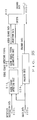
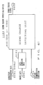
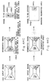
- Figure 1 is a basic block diagram showing a conventional image data encoding device for encoding a multivalue image according to the ADCT.
- a multivalue image is divided into a plurality of blocks each comprising 8 x 8 picture elements, and inputted in block units from a terminal 134a to a DCT unit 134c through a block buffer 134b.
- the DCT unit 134c orthogonally transforms through a two-dimensional DCT an input image signal for 8 x 8 picture elements into 8 x 8 two-dimensional DCT coefficients distributed as spatial frequencies, and outputs them to a quantizing unit 134d.
- the quantizing unit 134d linearly quantizes each of the inputted 8 x 8 two-dimensional DCT coefficients using a corresponding quantization threshold 134e in a quantization matrix not shown in Figure 1.
- a two-dimensional DCT coefficient smaller than the above described corresponding quantization threshold 134e is set to "0", while DC components (direct current coefficient) and a small amount of AC components (alternating current coefficient) indicate a value other than "0".
- quantized coefficients linearly quantized by the quantizing unit 134d are applied to a variable-length encoding unit 134f.
- the variable-length encoding unit 134f refers to a Huffman code table comprising Huffman tables provided for DC components and AC components separately, and encodes an input quantized coefficient string to variable-length codes. That is, for DC components, it refers to a one-dimensional Huffman table, and encodes the difference between the leading DC component and the previous DC component into variable-length codes. For AC components, it refers to a two-dimensional Huffman table, and encodes to variable-length codes the combination of a significant coefficient having a value other than "0" (index) and the run-length of an insignificant coefficient having the value "0" before the significant coefficient. Thus, the variable-length encoding unit 134f encodes DC and AC components into variable-length codes according to the above described Huffman code table 134g, and outputs the encoded data from a terminal 134h.
- a quantized coefficient can be determined according to a two-dimensional DCT coefficient and a corresponding quantization threshold 134e in a quantization matrix. The process is performed in block units on all the blocks of one image (one frame). Thus, two-dimensional DCT coefficients for one image (one frame) can be quantized.
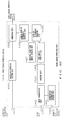
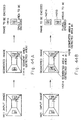
- Figure 2 is a block diagram showing a static image reconstructing device for reconstructing an original image from data encoded to variable-length codes.
- the static image reconstructing device reconstructs an original image from encoded data applied to a terminal 135a through a variable-length code decoding unit 135b, a quantizing unit 135c, and an inverse DCT unit in the order reverse to that for the encoding process shown in Figure 1.
- the reconstructed image is sequentially written at corresponding addresses of an image memory 135e to complete the reconstruction of one screen of an image.
- the data encoded by the static image encoding device are applied in block units from the input terminal 135a to the variable-length code decoding unit 135b via predetermined transmission lines.
- variable-length code decoding unit 135b decodes quantized coefficients containing DC and AC components in each block according to a Huffman code table 135f used in the above described variable-length encoding process.
- a dequantizing unit 135c decodes the quantized coefficients containing DC and AC components in each block to two-dimensional DCT coefficients using a quantization threshold 135g used in the above described variable-length encoding process.
- the inverse DCT unit 135d performs an inverse two-dimensional DCT using the decoded two-dimensional DCT coefficients in each block, and reconstructs an image signal for each picture element in each block.
- the reconstructed image signal for each picture element in each block is written to the image memory 135e in block units.
- a writing of an image signal for each picture element in each block to the image memory 135e can be controlled by an intra-block picture element write control unit 135h. That is, the intra-block picture element write control unit 135h controls a block address generating unit 135i such that the block address generating unit 135i outputs an address of a corresponding block in which a picture element signal is to be written, thereby controlling the writing of a reconstructed image in each frame to the image memory 135e in block units.
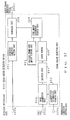
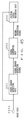
- Figure 3 shows the configuration of the basic part of a conventional moving picture encoding device for encoding moving picture data by an inter-frame prediction encoding method based on the interrelation between the images in the present and previous frames.
- Moving picture in each scene is applied to a difference image generating unit 136b through an input terminal 136a.
- An image memory 136c stores standard images (reconstructed images used as images in previous frames).
- the difference image generating unit 136b obtains the difference image between a standard image stored in the image memory 136c and the present image (an image in the present frame) applied to the above described input terminal 136a, and stores the difference image in a block buffer 136d.
- the difference image is obtained for each block containing 8 x 8 picture elements. Therefore, the block buffer 136d stores the difference image (block difference image) indicating the difference between the images in the present and previous frames, each comprising 8 x 8 picture elements, at corresponding positions.
- a DCT unit 136e performs a two-dimensional DCT on a difference block image comprising 8 x 8 picture elements stored in the block buffer 136d, obtains 8 x 8 two-dimensional DCT coefficients, and outputs them to a quantizing unit 136f.
- the quantizing unit 136f linearly quantizes inputted two-dimensional DCT coefficients by a visually adaptive threshold, and obtains 8 x 8 quantized coefficients.
- the 8 x 8 quantized coefficients are zigzag scanned and outputted to a variable-length encoding unit 136g in the order of DC components, AC components having a low spatial frequency, and AC components having a high spatial frequency.
- variable-length encoding unit 136g encodes the inputted 8 x 8 quantized coefficients to variable-length codes according to a Huffman code table 136h, and stores the obtained encoded data in a code buffer 136i.
- the 8 x 8 quantized coefficients outputted from the quantizing unit 136f are applied to a dequantizing unit 136i, and the dequantizing unit 136i decodes the coefficients to 8 x 8 two-dimensional DCT coefficients.
- An inverse DCT unit 136k performs an inverse two-dimensional DCT using the 8 x 8 two-dimensional DCT coefficients, and reconstructs the difference block image.
- An adding unit 136m adds the reconstructed difference block image to the previous image in the corresponding block in the basic image stored in the image memory 136c, and rewrites the resultant image to the image memory 136c.
- the encoded data of a difference block image for all blocks of the present image are temporarily stored in the code buffer 136i by performing a series of the operations on all blocks of images in new frames inputted from the input terminal 136a, and then outputted by the terminal 136n.
- image data in the present frame are not encoded as is, but the image indicating the difference between the previous and present frames is encoded, thus successfully reducing the number of codes to be processed.
- the difference image reconstructed using the encoded data of the difference image is added to the image in the image memory 136c. Then, the image memory 136c stores the image identical to that reconstructed by the reconstructing unit based on the encoded data of the difference image and put in the present frame. The image is used as an image in the previous frame of a standard image when an image in the next frame is applied from the input terminal 136a.
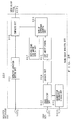
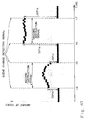
- Figure 4 shows the configuration of the basic part of a conventional moving picture reconstructing device for reconstructing an original image from the encoded data outputted by the above described moving picture encoding device.
- variable-length code decoding unit 137b decodes them to quantized coefficients in block units according to a Huffman code table 137c similar to the Huffman code table 136h in the conventional moving picture encoding device.
- a dequantizing unit 137d dequantizes a decoded quantized coefficient in each block according to a quantization matrix (similar to the quantization matrix used by the dequantizing unit 136i in the conventional moving picture encoding device shown in Figure 3) not shown in Figure 4.
- An inverse DCT unit 137e performs an inverse two-dimensional DCT in block units using decoded two-dimensional DCT coefficients in each block, and reconstructs a difference image in each block.
- An adding unit 137f adds the reconstructed difference image in each block to an image in the corresponding block in an image memory 137g, and rewrites the resultant image in the image memory.
- the writing of a reconstructed image in the image memory 137g for each block can be controlled by an intra-block picture element write control unit 137h. That is, the intra-block picture element write control unit 137h controls a block address generating unit 137i such that the block address generating unit 137i outputs to the image memory 137g an address of a block in which a difference image should be stored in the image memory 137g, thereby successfully writing a reconstructed image of each frame in block units.
- the image memory 137g stores a reconstructed image of each frame by performing a series of the above described processes on encoded data of difference images of all blocks forming an image in each frame.
- picture signals accumulated in a storage device are edited.
- the editing operation is performed manually by an editor by combining picture sources (images) and regenerating pictures to be broadcast. At this time, the head of a combined picture source (change of scenes) can be visually identified in regenerating pictures.
- the portion (frame) to be regenerated can be detected by visually determining the change of pictures (scene-changed frame or change of scenes) while regenerating pictures at a high speed.
- a recording system for recording moving picture data responsively to motions in pictures can be produced by controlling the recording system according to the extracted information on changes of scenes, only the changes of scenes can be regenerated among a series of recorded moving picture data by recording the extracted information on changes of scenes together with picture information or encoded data, or only the changes of scenes can be recorded and regenerated according to extracted information on changes of scenes.
- moving picture is composed of a series of static images
- the moving picture can be encoded and reconstructed by an encoder and a decoder to be used for processing static images.
- An encoder for static images has the advantage over that for moving picture that it is based on a simpler method and has a smaller circuit.
- the above described static image encoding method has aimed at reducing the amount of data to be accumulated and transmitted, other applications such as automatically extracting frames containing changes of scenes from recorded moving picture data have never been expected at all.
- the present invention aims at providing a method and system for performing the following operations with the above described encoder having a small circuit for static images.
- an image data encoding method for encoding image data comprising:
- an image data encoding device for encoding image data comprising:
- the device detects a scene-changed frame according to the difference in the amount of codes between adjacent frames. It outputs only encoded image data for a normal frame, that it, a scene-unchanged frame. If a frame is a scene-changed frame, it outputs encoded data together with code data indicating that the frame is a scene-changed frame.
- an image reconstructing unit can easily identify encoded data of a scene-changed frame from those of a scene-unchanged frame according to the existence of the code data indicating a scene-changed frame.
- a scene change detecting method comprising:
- a scene change detecting device comprising:
- the configuration detects a change of scenes according to the difference in the amount of codes of image data between adjacent frames, and externally outputs a scene change detection signal if a change of scenes has been detected.
- An image encoding method is disclosed in ICASSP.89 "Multi Dimensional Signal Processing Audio and Electro Acoustics", Vol. 3, pages 1858 to 1861, in which interframe motion detection is performed in units of one block and in which only the block whose motion is detected is encoded.
- this method the brightness level difference between pixels located at the same position is corresponding blocks in adjacent frames is evaluated.
- a block is considered to be moving if the number of moving pixels in the block, i.e. those having brightness differences exceeding a certain threshold, exceeds another threshold.
- this document neither discloses nor suggests either of a determining step or a scene change detecting means for detecting a change of scenes according to the amount of codes of adjacent frames and the conditions for detecting a change of scenes.
- EP0473384 teaches a frame dropping process in which motion between the blocks is detected from a difference of the pixel data between adjacent frames by sub-sampling.
- this document neither discloses nor suggests either of a determining step or scene change detecting means for detecting a change of scenes according to the amount of codes of adjacent frames and the conditions for detecting a change of scenes.
- US4809067 discloses a technique to use the code amount of encoded data for determining the validity of a block. It teaches an encoding apparatus which controls the degree of compression for each frame by determining the validity of each input block of a frame in vector quantisation, according to the comparison between the differential data (i.e. the differential between the input block and selected block) and certain threshold values, and it also changes and controls these threshold values according to the code amount of encoded data in a transmission data buffer. However, it does not teach using the code amount to detect the change of scene of an image. It also does not teach comparing the code amounts of image data between two consecutive frames, rather it teaches comparing the code amount of partial image data in a frame with threshold values. Further, this document teaches a method only for solving a problem arising from vector quantisation in units of blocks. However, an embodiment of the invention can use the code amount obtained in the encoding process without restricting the method used for encoding a block.
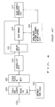
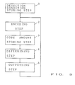
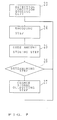
- the first image data encoding method comprises a detection condition storing step 1 of storing a detection condition set for detecting a scene-changed frame, an encoding step 2 of encoding image data of an input frame, a code amount storing step 3 of storing the amount of codes in the data, encoded in the encoding step 2, of previous and present frames, a determining step 4 of determining whether or not the present frame is a scene-changed frame according to the amount of codes of the previous and present frames stored in the code amount storing step 3 and to the condition set for detecting a scene-changed frame stored in the detection condition storing step 1, and an output step 5 for outputting, as a determination result of the determining step 4, the encoded data generated in the code amount storing step 3 and a code indicating a scene-changed frame if the present frame is a scene-changed frame, and only the encoded data if the present frame is not a scene-changed frame.
- the method is configured such that the above listed encoding step 2, the code
- FIG. 6 is the block diagram indicating the principle of the first image data encoding device.
- the image data encoding device comprises a frame encoding unit 8 for sequentially encoding image data in an input frame, a frame encoded data storing unit 9 for storing encoded data of frames whose data are encoded by the frame encoding unit 8, a detection condition storing unit 10 for storing the condition set for detecting that a frame encoded by the frame encoding unit 8 is a scene-changed frame, a scene-changed frame detecting unit 11 for detecting a scene-changed frame according to the difference in the amount of codes between the encoded data in the previous frame stored in the frame code storing unit 9 and the data, encoded by the frame encoding unit 8, in the present frame, and to the detection condition stored by the detection condition storing unit 19, and an output unit 12 for outputting encoded data stored in the frame code storing unit 9 and encoded data indicating a scene-changed frame for a scene-changed frame detected by the scene-changed frame
- the above described detection condition storing unit 10 stores as the detection condition of a scene-changed frame a standard value of the difference in the amount of codes between adjacent frames, for example. It also stores as the detection condition of a scene-changed frame the standard value of the rate of difference in the amount of codes between adjacent frames, for example.
- FIG. 7 is the flowchart indicating the principle of the first scene change detecting method.
- the scene change detecting method comprises a detection condition storing step 23 of storing a detection condition set for detecting changes of scenes in moving picture data, an encoding step 24 of encoding image data in a frame, a code amount storing step 25 of storing the amount of codes, in a frame, encoded by the encoding step 24, a scene change determining step 26 of determining a change of scenes according to the amount of codes of the previous and present frames stored by the code amount storing step 25 and to the detection condition stored by the detection condition storing step 23, and a change signal outputting step of outputting a scene change detection signal according to the determination result of the scene change determining step 26.
- the above described encoding step 24 reduces an original image and performs an encoding process on image data having the reduced amount of data.
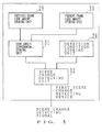
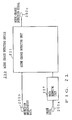
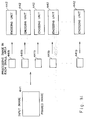
- Figure 8 is the block diagram indicating the principle of the first scene change detecting device 1500.
- the scene change detecting device comprises a detection condition storing unit 28 for storing the condition set for detecting changes of scenes in moving picture data, a previous frame code amount storing unit 29 for storing the amount of codes in image data in the previous frame, a present frame code amount storing unit 30 for storing the amount of codes in image data in the present frame, a code difference storing unit 31 for obtaining the difference between the amount of codes in the previous frame stored in the previous frame code amount storing unit 29 and the amount of codes in the present frame stored in the present frame code amount storing unit 30, and storing the difference, and a scene change detecting unit 32 for detecting changes of scenes according to the difference in the amount of codes stored in the code difference storing unit 31 and to the detection condition stored in the detection condition storing unit 28, and outputting a scene change detection signal when changes of scenes are detected.
- a detection condition storing unit 28 for storing the condition set for detecting changes of scenes in moving picture data
- a previous frame code amount storing unit 29 for storing the amount of codes in image data in the
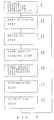
- Figure 9 is the flowchart indicating the principle of the second image data encoding method.
- the image data encoding method comprises a scene change detection condition storing step 41 of storing the condition set for detecting a change of scenes, an area dividing step 42 of dividing image data in an input frame to a plurality of small areas, an encoding step 43 of encoding the image data separately for each small area of the input frame obtained in the area dividing step 42, a code amount storing step 44 of calculating and storing the amount of codes of encoded data in each small area obtained in the encoding step 43, a code amount difference calculating step 45 for obtaining a predetermined difference in the amount of codes between the present frame and the previous frame in each small area according to the amount of codes of the present and previous frames in each small area stored in the code amount storing step 44, a determining step 46 for determining whether or not the present frame is a scene-changed frame according to the difference calculated in the code amount difference calculating step 45 in the amount of codes in each small area between the present frame and the previous frame, and to the detection condition stored in the scene change detection condition storing step 41
- the second image data-encoding method can also be designed as follows, for example. That is, a detection condition stored in the scene change detection condition storing step 41 refers to a standard value of the sum of absolute values of the differences between the present and previous frames for all small areas.
- the code amount difference calculating step 45 obtains the difference in the amount of codes between the present and previous frames for each small area.
- the determining step 46 obtains the sum of absolute values of the differences in the amount of codes between the present and previous frames, and the sum can be compared with the standard value to detect a scene-changed frame.
- detection information stored in the scene change detection condition storing step refers to the standard value of the average rate of difference in the amount of codes between the present and previous frames for each small area.
- the code amount difference calculating step 45 obtains the rate of the difference between the present and previous frames for each small area.
- the determining step 46 can obtain the average rate of difference in the amount of codes between the present and previous frames for each small area to detect a scene-changed frame by comparing the average rate of difference with the above described standard value.
- the area dividing step 42 can divide an input frame to two small areas, that is, odd fields and even fields.
- the area dividing step 42 can divide an input frame to small areas each indicating a color component when the input frame refers to colored image data.
- the area dividing step 42 can equally divide an input frame to a plurality of blocks as small areas.
- image data in a small areas can be encoded in parallel in the encoding step 43.
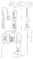
- FIG. 10 is the block diagram indicating the principle of the second scene change detecting device 1600 and the second image data encoding device.
- the second scene change detecting device 1600 comprises a detection condition setting unit 55 for storing the condition set for detecting a scene-changed frame, a small area dividing unit 56 for dividing image data in an input frame to a plurality of small areas, an encoding unit 57 for individually encoding image data in the plurality of small areas obtained by the small area dividing unit 56, a previous frame small area code amount storing unit 58 for calculating and storing the amount of codes of data, encoded by the encoding unit 57, in all small areas in the previous frame, a code amount difference calculating unit 59 for calculating the amount of codes of data, encoded by the encoding unit 57, in all small areas in the present frame, and obtaining the difference in the amount of codes between the present and previous frames in each small area according to the obtained amount of codes in each of the small areas in the present frame and to the amount of codes in each of
- the second scene change detecting device 1600 can also be designed as follows, for example. That is, the detection condition setting unit 55 stores as the detection condition the standard value of the sum of the absolute values of the differences in the amount of codes between the present frame and the previous frame for all small areas.
- the code amount difference calculating unit 59 obtains the difference in the amount of codes between the present frame and the previous frame for each of the small areas.
- the scene-changed frame detecting unit 60 obtains the sum of differences in the amount of codes between the present frame and the previous frame for all small areas, and detects a scene-changed frame by comparing the sum with the above described standard value.
- the detection condition setting unit 55 stores as the detection condition the standard value of the average rate of difference in the amount of codes between the present frame and the previous frame.
- the code amount difference calculating unit 59 obtains the rate of the difference in the amount of codes between the present frame and the previous frame for each of the small areas.
- the scene-changed frame detecting unit 60 obtains the average rate of difference in the amount of codes between the present frame and the previous frame for small areas, and compares the average rate of difference with the above described standard value.
- the second image data encoding device comprises the second scene change detecting device, a frame encoding unit 61 for encoding image data applied to the scene change detecting device, and a data outputting unit 62 for outputting a code indicating a scene-changed frame together with the data, encoded by the frame encoding unit 61, of the image data if a frame is determined to be a scene-changed frame by the scene change detecting device, and for outputting only the data, encoded by the frame encoding unit 61, of the image data if a frame is determined not to be a scene-changed frame.
- Figure 11 is the block diagram indicating the principle of the third image data encoding device.
- the image data encoding device comprises the second scene change detecting device, a frame encoding unit 63 for encoding image data applied to the scene change detecting device, a change frame storing unit 64 for storing the identification information on the frame detected as being a scene-changed frame by the scene change detecting device, and a data output unit 65 for sequentially outputting image data encoded by the frame encoding unit 63 and for outputting the identification information on all scene-changed frames stored in the scene-changed frame storing unit after all encoded data have been outputted.
- Figure 12 is the flowchart indicating the principle of the second scene change detecting method.
- the scene change detecting method is a scene change detecting method for detecting a change of scenes in moving picture data. It comprises a segmentation information storing step 72 of storing segmentation information which indicates all areas to be extracted from image data in input frames, a detection condition storing step 73 of storing the condition set for detecting a scene-changed frame in which an image indicates the difference from that in the previous frame, an image segmenting step 74 of segmenting image data in all areas specified by the segmentation information from among image data in input frames according to the segmentation information stored in the segmentation information storing step 72, an encoding step 75 of encoding image data in all areas segmented in the image segmenting step 74, a code amount storing step 76 of storing the amount of codes of the data, encoded in the encoding step 75, in all areas in the previous frame, a code amount difference calculating step 77 of calculating a predetermined difference between the amount of codes in the data encoded by the encoding step 75 in all specified areas in the present frame and the amount of
- the second scene change detecting method can also be designed as follows. That is, the detection condition stored in the detection condition storing step 73 refers to the standard value of the sum of the absolute values of the differences in the amount of codes.
- the code amount difference calculating step 77 obtains the sum of the differences in the amount of codes between the present frame and the previous frame for all specified areas.
- the scene change detecting step 78 determines whether or not there is a change of scenes between the present frame and the previous frame in a specified area by comparing the sum of the absolute values of the differences in the amount of codes calculated in the code amount difference calculating step 77 with the above described standard value.
- the detection condition stored in the detection condition storing step 73 refers to the standard value of the average rate of difference in the amount of codes.
- the code amount difference calculating step 77 obtains the average rate of difference in the amount of codes between the present frame and the previous frame for all specified areas.
- the scene change detecting step 78 determines whether or not there is a change of scenes between the present frame and the previous frame in a specified area by comparing the average rate of difference in the amount of codes calculated in the code amount difference calculating step 77 with the above described standard value.
- the image segmenting step 74 can be designed to segment image data of a specified area in compressed image data obtained by compressing original image data in a frame by a predetermined compressing method.
- FIG. 13 is the block diagram indicating the principle of the third scene change detecting device 1700 and the fourth scene change detecting device 1800.
- the third scene change detecting device 1700 detects a change of scenes in moving picture data. It comprises a segmentation information storing unit 81 for storing segmentation information which indicates all areas to be extracted from image data in input frames, a detection condition storing unit 82 for storing the condition set for detecting a scene-changed frame in which an image indicates the difference from that in the previous frame, an image segmenting unit 83 for segmenting image data in all areas specified by the segmentation information from among image data in input frames according to the segmentation information stored in the segmentation information storing unit 81, an encoding unit 84 for encoding image data in all areas segmented in the image segmenting unit 83, a code amount storing unit 85 for storing the amount of codes of the data, encoded in the encoding unit 84, in all areas in the previous frame, a code amount difference calculating unit 86 for calculating a predetermined
- the third scene change detecting device 1700 can also be designed as follows, for example. That is, the detection condition refers to the standard value of the sum of the absolute values of the differences in the amount of codes.
- the code amount difference calculating unit 86 obtains the sum of the differences in the amount of codes between the present frame and the previous frame for all specified areas.
- the scene change detecting unit 87 determines whether or not there is a change of scenes between the present frame and the previous frame in a specified area by comparing the sum of the absolute values of the differences in the amount of codes calculated in the code amount difference calculating unit 86 with the above described standard value.
- the detection condition can refer to the average rate of difference in the amount of codes.
- the code amount difference calculating unit 86 obtains the average rate of difference in the amount of codes between the present frame and the previous frame for all specified areas.
- the scene change detecting unit 87 determines whether or not there is a change of scenes between the present frame and the previous frame in a specified area by comparing the average rate of difference in the amount of codes calculated in the code amount difference calculating unit 86 with the above described standard value.
- the encoding unit 84 can encode image data simultaneously for these areas as if they were a single area.
- the fourth scene change detecting device 1800 can be designed such that it further comprises, in addition to the third scene change detecting device, a data reducing unit 89 for reducing image data of input frames by a predetermined method.
- the image segmenting unit 82 segments image data of a specified area in the image data, compressed by the data reducing unit 89, in input frames.
- the image segmenting unit 82 can be designed to mask the image data in input frames for the areas other than a specified area, and output to the encoding unit 84 the image data obtained by the masking process as image data to be encoded.
- the first image data encoding method and the first image data encoding device detects a scene-changed frame (a frame indicating a change of scenes) based on the difference in the amount of codes between adjacent frames, and outputs a code indicating a scene-changed frame at the detection of a scene-changed frame. Accordingly, moving picture data are encoded such that encoded data indicating a scene-changed frame can be easily discriminated against those of a normal frame (a frame containing no change of scenes).
- the encoded data indicating a scene-changed frame are extracted to reconstruct original image data from moving picture data encoded according to the first image data encoding method and the first image data encoding device. Accordingly, only the encoded data indicating a scene-changed frame can be extracted from encoded moving picture data and the images for the scene-changed frame can be displayed on a screen in a predetermined format.
- a change of scenes in moving picture data can be detected according to the difference in the amount of codes between the present frame and the previous frame and to a predetermined detection condition (standard value), and a scene change detection signal can be outputted to an external device at the detection of a change of scenes.
- a frame is divided into a plurality of small areas, and a difference (an absolute value of the difference in the amount of codes or a rate of the difference in the amount of codes). Then, the total difference in the amount of codes between the present frame and the previous frame (the sum of the absolute values of the differences in the amount of codes for all small areas, or an average rate of difference in the amount of codes for all small areas) is obtained. Then, the difference is compared with a predetermined detection condition (standard value) to detect a scene-changed frame in which a scene is different from that in the previous frame. At the detection of a scene-changed frame, an external scene change signal is outputted. Thus, a scene-changed frame can be detected with high precision.
- a predetermined detection condition standard value
- moving picture data can be encoded such that encoded data of a detected scene-changed frame can be easily extracted from normal frames (scene-unchanged frames).
- a change of images (change of scenes) in a specific area can be detected based on the difference in the amount of codes in the specific area in adjacent frames.
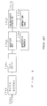
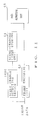
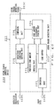
- Figure 14 is the block diagram showing the moving picture encoding device according to the first embodiment.
- moving picture data to be externally encoded in a series of frames are applied to input terminal 110a.
- An encoding unit 111 sequentially encodes image data applied to input terminal 110a in frame units.
- a code buffer 112 stores encoded data in a frame generated by the encoding unit 111, calculates the amount of codes in the encoded data, and outputs the encoded data and the amount of codes respectively to a switch 115 and a scene change determining unit 113.
- Detection condition designation data are used to detect a change of scenes in moving picture and designate the difference in the amount of codes (absolute value of the difference in the amount of codes) between adjacent frames. These data are applied to input terminal 110b.
- a detection condition setting unit 114 sets a detection condition.
- the scene change determining unit 115 detects a change of scenes according to the detection condition set by the detection condition setting unit 114.
- the scene change determining unit 113 calculates the difference between the amount of codes in a frame applied from the code buffer 112 (the amount of codes in the present frame) and the amount of codes in the previous frame. If the difference indicates a value larger than that determined as the detection condition (difference in the amount of codes) by the detection condition setting unit 114, the scene change determining unit 113 outputs to the switch 115 a COS (change of scene) code indicating a change of scenes together with an active selection signal.
- the switch 115 outputs encoded data in the present frame applied from the code buffer 112 when a selection signal is not active.
- the switch 115 When a selection signal is active, the switch 115 adds to the encoded data the COS code applied together with the selection signal, thus generating encoded data indicating a change of scenes. Then, the encoded data replace the above described normal encoded data (encoded data in a frame containing no change of scenes), and are outputted externally through output terminal 110c.
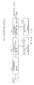
- Figure 15 is the block diagram showing an example of the configuration of the encoding unit 111 of the moving picture encoding device.
- An encoding unit for static images is used in the example.
- the encoding unit 111 comprises image data input terminal 120a for applying, in block units, multivalue image data divided into a plurality of blocks each comprising 8 x 8 picture elements, a two-dimensional DCT unit for orthogonally transforming by a two-dimensional DCT an image signal for the applied 8 x 8 picture elements to 8 x 8 two-dimensional DCT coefficients distributed as spatial frequencies and outputting the result, a linearly quantizing unit 123 for linearly quantizing each of the two-dimensional DCT coefficients according to a corresponding quantization threshold in a quantization matrix 122, a variable-length encoding unit 124 for receiving quantized coefficients obtained by the linear-quantization performed by the linearly quantizing unit 123 and encoding a string of the quantized coefficients to variable-length codes by referring to a code table 123 containing a Huffman code list provided separately for DC components and AC components, and encoded data output terminal 120b for outputting the data encoded by the encoding unit.
- the data encoded by the encoding unit 111 meet the JPEG Standard. Since the JPEG Standard originally applies to encoded data for static images, it contains no rules on encoded data for moving picture. That is, it has no description of a frame (refer to Chapter 1 of the "International Standards on Multimedia Encoding" by YASUDA, Hiroshi published by Maruzen in 1991).
- the encoded data in accordance with the JPEG Standard is edited by the encoding unit shown in Figure 22 into a plurality of encoded data groups corresponding to moving picture data.
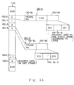
- Figure 24 shows the configuration of the encoded data groups.
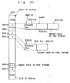
- Encoded data groups 130 shown in Figure 16 show a sequence of data (data in a series of frames). The sequence starts with a SOM (start of motion) code indicating the header of encoded data groups 130 of moving picture, and ends with an EOM (end of motion) code indicating the end of the groups.
- the groups comprise encoded data areas of each frame 130-0, 130-1, 130-2, 130-3, ..., 130-n between the header and the end of the groups.
- corresponding encoded data area 130-i comprises, as indicated for encoded data area 130-0, frame number 130-0a, encoded data area 130-0b for one static image, and a COS code indicating a scene-changed frame between these areas.
- encoded data area 130-i can be configured by frame number 130-3a and encoded data area 130-3b for one static image only.
- encoded data groups 130 are designed such that a reconstructing unit can easily extract encoded data 130-i in a scene-changed frame according to the existence of a COS code.
- Figure 17 shows another example of the configuration of the encoded moving picture data groups
- encoded data groups 140 starts with an SOM code added to the header of the sequence, and ends with an SOM code.
- Additional data 140-F is added between the last encoded data area 140-n and an EOM code.
- the additional data 140-F stores data 140-F1 indicating the number of detected changes of scenes (the number of scene-changed frame), and scene-changed frame numbers 10, 65, ... 600, for example, for the number of scene-changed frames.
- the switch 115 of the encoding device shown in Figure 22 is set such that encoded data applied from the code buffer 112 are outputted to encoded data output terminal 110c.
- the number of the COS code inputting operations performed by the scene change determining unit 113 is counted, and the frame number at this moment is stored in an internal buffer (not shown in Figure 14) to generate added data 140-F.
- the generated added data 140-F are inserted before the EOM code.
- scene-changed frames can be easily extracted from the above described encoded data groups 140 if all the encoded data groups 140 are referred to as an index file, and the added data 140-F, that is, the last portion of all data, containing scene-changed frame information are referred to as a pointer.
- Figure 18 is a flowchart showing the basic operation. The operation can be performed with each of the circuit blocks shown in Figure 14 controlled by the control unit (not shown in Figure 14 in the encoding unit.
- a condition for extracting a scene-changed frame (detection condition designation data) is set by the detection condition setting unit 114 (S151).
- a standard value indicating the difference in the amount of codes between adjacent frames is determined to detect a scene-changed frame.
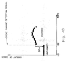
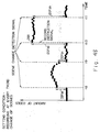
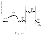
- TV images for example, are sequentially encoded in series at a rate of 30 pieces of static images per second.
- the amount of codes is outputted in megabyte units for each static image.
- the amount of codes does not vary very much with a little movement of a character in a scene. However, when a scene is changed from a character to a building, etc. of a background, it indicates a large difference.
- step S151 detects a change of scenes (scene-changed frame) according to the feature that the amount of codes fluctuates if a different scene has appeared. Then, the detection condition setting unit 114 sets as a condition for extracting a scene-changed frame the difference in the amount of codes between two frames to be compared.
- the encoding unit 111 determines it after receiving through input terminal 110a the data indicating the end of images (EOM code). Thus, it is determined whether the encoding process is to be continued or to terminate.
- the encoding unit 111 encodes the image data in the next frame applied through input terminal 110a (S153), and the scene change determining unit 113 determines whether or not the frame is a scene-changed frame (S154).
- the scene determining unit 113 calculates the difference between the amount of codes in the present frame inputted from the code buffer 112 and the amount of codes of image data in the previous frame inputted previously and stored internally, and determines the present frame to be a scene-changed frame when the absolute value of the calculated difference is larger than that of the difference set in the detection condition setting unit 114.
- the scene change determining unit 113 does not turn a selection signal outputted for the switch 115 active, but outputs only the encoded data applied from the code buffer 112 (S156). That is, the switch 115 outputs to output terminal 110c the encoded data "as is" applied from the code buffer 112 according to the instruction of a selection signal entered from the change-scene determining unit 113.
- the change scene determining unit 113 determines a scene-changed frame, it turns a selection signal active to inform the switch 115 of a change of scenes, and simultaneously outputs a COS code (S155).
- the switch 115 outputs the number of the scene-changed frame followed by the above described COS code and the encoded data in the scene-changed frame when encoded data groups 130 shown in Figure 16 are generated. If encoded data groups 140 shown in Figure 25 are generated, the switch 115 counts the number of the COS code inputting operations, and internally stores the number of the scene-changed frame, and then outputs through output terminal 110c the number of the scene-changed frame followed by the encoded data in the scene-changed frame.
- Figure 19 is the block diagram of the circuit of a moving picture image encoding unit according to the second embodiment.
- the encoding unit comprises terminal 200a for applying image data, an encoding unit 201 for efficiently encoding image data inputted from terminal 200a according to the above described ADCT, etc., and output terminal 20b for externally outputting the data encoded by the encoding unit 201.
- the encoding unit 201 is designed similarly to the encoding unit 111 of the moving picture encoding device according to the first embodiment shown in Figure 14.
- the moving picture encoding unit according to the third embodiment only efficiently encodes image data, and does not detect a scene-changed frame during the encoding process.
- original image data are not necessarily reconstructed from encoded data. That is, the encoded data can be used such that only scene-changed frames are detected in encoded data (only scene changes are detected), and the detection results are effectively used to control normal image recording and regenerating units for other devices such as video tape recorders, etc.
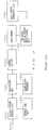
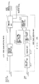
- Figure 20 is the block diagram showing a scene change detecting device 220 for detecting a change of scenes in a series of recorded moving picture data.
- the scene change detecting device 220 comprises a scene change detecting unit 221 for detecting a scene change in the moving picture data, terminal 200a through which framed image data of moving picture are provided for the scene change detecting unit 221, terminal 200b through which detection designation data are provided for the scene change detecting unit 221, and terminal 200c through which a scene change detection signal indicating that a change of scenes has been detected is externally outputted.
- the encoding unit 221 efficiently encodes through the ADCT, etc. the framed image data inputted through input terminal 200a.
- a code buffer 222 receives and stores 1-frame encoded data generated by the encoding unit 221, and calculates the encoded data.
- a previous frame code amount storing unit 223 stores the amount of codes of the image data in the previous frame after receiving them from the code buffer 222.
- a code amount difference storing unit 224 calculates and stores the difference between the amount of codes in the previous frame received from the previous frame code amount storing unit 223 and the amount of codes in the present frame received from the code buffer 222.
- a detection condition setting unit 225 sets a detection condition (a standard value indicating the difference in the amount of codes) for a change of scenes designated according to the detection designation data received through input terminal 200b.
- a comparing unit 226 compares the detection condition (a standard value indicating the difference in the amount of codes) set by the detection condition setting unit 223 with the absolute value of the difference in the amount of codes received from the code amount difference storing unit 224, generates a scene change detection signal if it has detected a change of scenes (a scene-changed frame), and outputs it through output terminal 200c.
- the comparing unit 226 compares the two code amount differences and determines that a different scene has appeared if the absolute value of the code amount difference received from the code amount difference storing unit 224 is larger than a standard value for the code amount difference set by the detection condition setting unit 225.
- the scene change detecting device 220 shown in Figure 20 detects a change of scenes while encoding 1-frame image data as is. It realizes a small size simple-circuit device by reducing the amount of data processed by the scene change detecting unit 221 after reducing the amount of input image data.
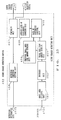
- Figure 21 is the block diagram showing a scene change detecting unit 230 as the fourth embodiment.
- the scene change detecting unit 230 is designed such that a data reducing unit 227 is provided between the scene change detecting unit 221 shown in Figure 20 and the image data inputting terminal 200a.
- the data reducing unit 227 reduces the amount of framed image data at a predetermined compression rate.
- Data compression is realized by representing colored image data by monochrome data, by representing framed image data by image data in either odd or even number fields, by omitting picture elements at a predetermined rate, combining two or more of the above described methods, etc. It is obvious that original data are retained if a compression rate is "0".
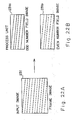
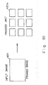
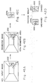
- Figures 22 through 25 show practical examples of reducing framed image data.
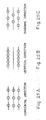
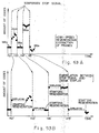
- Figure 22 shows a method of extracting and outputting either image data 231a in odd number fields or image data 231b in even number fields shown in Figure 22B from framed image data 231 shown in Figure 22A.
- the data compression rate is "1/2".
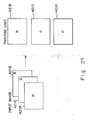
- Figure 23 shows a method of processing monochrome data by extracting, for example, G data from colored image data in a frame represented by three primary color signals R (red), G (green), and B (blue). That is, as shown in Figure 23A, for example, the contents of G memory 232G are extracted and outputted when each of R, G, and B signals is stored in R memory 232R, G memory 232G, and B memory 232B respectively. It is not limited to G data, but R or B data can be extracted for output.
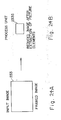
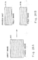
- Figure 24 shows a method of obtaining compressed image data 233s as shown in Figure 24B by omitting at a predetermined rate (subsampling) picture elements in the framed image data 233 shown in Figure 24A.
- Data can be omitted by one of the following methods, for example:
- method 3 excels in visibility.
- Data can be omitted adaptively, not fixedly as described above.
- image data are compressed by the data reducing unit 227, and processed by the scene change detecting unit 220 to detect a change of scenes. Then, a scene change signal is outputted from the scene change detecting unit 220 if a change of scenes has been detected.
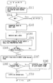
- Figure 26 shows the operation of detecting a change of scenes performed by the scene change detecting devices 220 and 230.
- Figure 26 is a flowchart for explaining the basic operation of the scene change detecting devices 220 and 230. The operation is executed such that each block shown in Figure 20 is controlled by a control unit not shown in Figure 26 provided in the scene change detecting unit 221.
- the amount of codes is initialized in Figure 26 (S241). That is, the amount of codes stored in each of the code buffer 222, the previous frame code amount storing unit 223, and the code amount difference storing unit 224 shown in Figure 20 is cleared and initialized.
- the extraction condition for a change of scenes (difference in the amount of codes) is set (S242). That is, detection designation data are entered through terminal 200b, and the detection condition setting unit 225 is set to the standard value of the absolute value of the difference in the amount of codes to detect a change of scenes according to the designation data.
- the process is immediately terminated. If not ("No" in S243), the image data in the next frame are encoded (S244). That is, the encoding unit 221 encodes image data in the frames next entered through terminal 200a, and stores in the code buffer 222 the encoded data in the entered frame (the present frame). The code buffer 222 calculates and stores the amount of codes in the encoded data inputted to the buffer.
- the code amount difference storing unit 224 receives the amounts of codes in the previous and present frames from the previous frame code amount storing unit 223 and the code buffer 222 respectively, and calculates and stores the difference between them (S245)
- the scene change detecting device compares the detection condition (a standard value of the absolute value of the code amount difference) set in the detection condition setting unit 223 with the absolute value of the code amount difference stored by the code amount difference storing unit 224, and determines that a change of scenes has been detected if the absolute value of the code amount difference stored in the code amount difference storing unit 224 is larger than the standard value of the absolute value of the code amount difference stored in the detection condition setting unit 223.
- the comparing unit 225 externally outputs a scene change detection signal through terminal 200c if it has detected a change of scenes as a result of the determination (S247). Then, a succeeding process is performed as described later.
- the code buffer 222 transfers the amount of codes of the encoded data in the present frame to the previous frame code amount storing unit 223, and the previous frame code amount storing unit 223 internally stores the amount (S248).
- the amount of codes is used as the "amount of data in the previous frame" in the similar calculation performed in the succeeding process.
- the process in S248 is immediately performed. That is, in this case, the amount of codes stored by the previous frame code amount storing unit 223 is stored as is.
- the moving picture encoding device shown in Figure 14 and the scene change detecting devices 220 and 230 shown in Figures 20 and 21 detect a change of scenes (scene-changed frame) based on an image in an entire frame. That is, a change of scenes is detected based on the difference in the amount of codes in the image data in the entire frame between adjacent frames.
- Figure 27 is a flowchart for explaining the fifth embodiment of the present invention for encoding image data.
- an extraction condition to detect a scene-changed frame (a frame whose image has been changed from the one in the previous frame, that is, a change of scenes) (341).
- the extraction condition refers to, for example, a standard value of the sum of the absolute values of the code amount differences, or the standard value of the average rate of difference in the amount of codes, etc.
- Image data can be divided to small areas as follows according to the method shown in Figure 41 through 39.
- scale data necessary for detecting a change of scenes are obtained based on the difference in the amount of codes of all small areas as being calculated in the above described process S345 (S347).
- the scale data are, for example, the sum of the absolute values of the code amount differences of all small areas, an average rate of difference in the amount of codes in a small area between the previous and present frames, etc.
- the scale data are obtained, they are compared with the extraction condition (standard value) set in the process S341, and it is determined whether or not the present frame refers to a scene-changed frame (a change of scenes) (S348).
- the present frame is considered to refers to a scene-changed frame (a change of scenes). If it is smaller than the standard value, then it is considered to refer to a scene-unchanged frame.
- the present frame refers to a scene-changed frame (a change of scenes) ("Yes" in S348), then the number of the present scene-changed frame is outputted (S349) and the encoded data in the present frame are outputted (S350).
- framed image data are divided to a plurality of small areas.
- the sum of the absolute values of the differences or an average rate of difference can be obtained. If the sum or the average rate of difference is larger than an experimentally obtained standard value, the present frame is determined to refer to a scene-changed frame (a change of scenes). In moving picture, it is rare that an entire image in a frame is changed completely. In most cases, only a part of a frame is changed. Thus, checking the difference in the amount of codes in a small area between the previous and present frames successfully detects a partial difference in a frame. Furthermore, the sum of the absolute values of the code amount differences in all small areas between the present and previous frames or an average rate of difference between the present and previous frames in small areas enables exact detection of a scene-changed frame.
- Figure 32 shows as the sixth embodiment of the present invention an example of the configuration of a scene change detecting device 400 for detecting a change of scenes according to the above described method.
- a small area dividing unit 401 divides 1-frame image data applied through input terminal 400a to a plurality of small areas. The dividing operation is performed by one of the above described methods shown in Figures 28 through 31.
- An encoding unit 402 sequentially receives image data in small areas in a predetermine order from the small area dividing unit 401, encodes the image data in each of the small areas separately according to the ADCT, etc., and outputs to a small area code amount storing unit 403 the data, encoded by the encoding unit, in each of the small areas.
- the small area code amount storing unit 403 calculates the amounts of codes of the encoded data in small areas after receiving them from the encoding unit 402, and stores the amounts of codes in small areas.
- a previous frame small area code amount storing unit 404 stores the amount of codes in each of the small areas in the previous frame calculated by the small area code amount storing unit 403.
- An inter-frame difference storing unit 405 receives the amounts of codes in the small areas in the present and previous frames from the small area code amount storing unit 403 and the previous frame small area code amount storing unit 404 respectively, calculates the difference between the present and previous frames in the amount of codes in the small areas, and obtains the sum of the absolute values of the differences calculated as described above for all small areas. The sum is outputted to a comparing unit 407.
- the small area code amount storing unit 403 outputs to the previous frame small area code amount storing unit 404 the total code amount in all small areas in the present frame, while the present frame small area code amount storing unit 404 updates the presently stored code amount to the amount of codes in the small areas of the present frame applied from the small area code amount storing unit 403.
- the last stored code amount is used as the code amount of the previous frame to obtain the difference in the amount of codes in the small areas of the image data next applied through input terminal 400a.
- a detection condition setting unit 406 receives detection designation data through input terminal 400b, and sets and internally stores the code amount difference designated by the detection designation data.
- the code amount difference refers to a standard value of the sum of the absolute values of the code amount differences which is used to detect a scene-changed frame.
- the comparing unit 407 When the comparing unit 407 receives from the inter-frame difference storing unit 405 the sum of the absolute values of the differences in the amount of codes in a small area of the present frame, it compares the sum with the code amount difference set by the detection condition setting unit 406. If the sum is larger than the preliminarily set code amount difference, then the present frame is considered to be a scene-changed frame (a change of scenes). At this time, the comparing unit 407 outputs a scene change detection signal (COS signal) through output terminal 400c, and outputs through output terminal 400d a selection signal active while the scene change detection signal (COS code) is effective. When the sum is smaller than the preliminarily set difference, none of the signals are outputted.
- COS signal scene change detection signal
- Figure 33 is the block diagram showing another example of a configuration of the scene change detecting unit.
- a scene change detecting device 450 is the seventh embodiment of the present invention, and detects a change of scenes according to a varied rate of difference in the amount of code in a small area between the present and previous frames.
- a small area dividing unit 451, an encoding unit 452, a small area code amount storing unit 453, and a previous small area code amount storing unit 454 are designed similarly to each of the blocks shown in Figure 45, that is, the small area dividing unit 401, the encoding unit 402, the small area code amount storing unit 403, and the previous frame small area code amount storing unit 404. Accordingly, the explanation of these blocks is omitted.
- a detection condition setting unit 456 sets and stores a rate of difference specified according to the detection designation data applied through input terminal 450b.
- the rate of difference is a standard value of the rate of difference in the amount of codes which can be used as a determination standard according to which a change of scenes can be determined.
- the rate-of-difference counting unit 455 receives the amounts of codes in all small areas in the previous and present frames from the previous small area code amount storing unit 454 and the small area code amount storing unit 453 respectively when the small area code amount storing unit 453 stores the amount of codes of encoded data in all small areas in the present frame. Then, it counts the rate of difference in the amount of codes for each of the small areas, and outputs to an average rate-of-difference counting unit 456 the rate of difference in the amount of codes of all small areas in the present frame.
- the average rate-of-difference counting unit 456 obtains an average value of the rates of differences in the amount of codes in all small areas in the present frame (an average rate of difference), and outputs it to a comparing unit.
- the comparing unit 457 compares the average value of the rate of difference in the amount of codes in small areas of the applied present frame with the standard average rate of difference applied from the detection condition setting unit 456, recognizes that the present frame is a scene-changed frame (a change of scenes) only when the average rate of difference is greater than the standard average rate of difference, and externally outputs a scene change detection signal (COS code) and an active selection signal through output terminal 450c and 450d respectively.
- COS code scene change detection signal
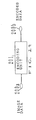
- Figure 34 shows an example of a configuration of the moving picture encoding device as the eighth embodiment of the present invention.
- the scene change detecting unit of the scene change detecting devices 400 or 450 is incorporated as a scene change detecting unit 510.
- the encoding device generates and outputs encoded data groups 130 in the format shown in Figure 24.
- 1-frame image data are applied through input terminal 500a like input terminal 400a or 450a as shown in Figures 32.
- detection designation data indicating the difference used as a standard value at the detection of a change of scenes are applied through input terminal 500b like input terminal 400b or 450b shown in Figure 32 or 33.
- the scene change detecting unit 510 has the same configuration as that of the scene change detecting device 400 or 450 shown in Figure 32 or 33 respectively. It divides 1-frame image into a plurality of small areas, encodes image data in each of the small areas, and detects a scene-changed frame (a change of scenes). If a scene-changed frame has been detected, a scene change signal and an active selection signal are outputted to a switch 530.
- An encoding unit 520 efficiently encodes moving picture data applied through input terminal 500a, and outputs to the switch 530 one-frame encoded data obtained by the encoding process.
- the configuration of the encoding unit 520 is the same as that of the encoding unit 111 for encoding data to variable-length codes according to, for example, the ADCT shown in Figure 14. That is, it encodes 1-frame image data applied through input terminal 500a to variable-length codes according to the ADCT, and generates and outputs the encoded data in accordance with the JPEG standard.
- the switch 530 outputs through output terminal 500c 1-frame encoded data applied by the encoding unit 520 when no active selection signals are applied from the scene change detecting unit 510.
- a scene change detection signal COS code
- COS code applied from the scene change detecting unit 510 is outputted through output terminal 500c as being added to the head of the encoded data meeting the JPEG standard and entered from the encoding unit 520.
- the moving picture encoding device generates and outputs encoded data groups 130 in the format shown in Figure 16.
- Figure 35 is the block diagram showing the moving picture encoding device according to the 9th embodiment of the present invention for generating and outputting encoded data groups 140 shown in Figure 25.
- input terminals 600a and 600b and output terminal 600c have the same function as that of input terminals 500a and 500b and output terminal 500c shown in Figure 34.
- a scene change detecting unit 610 and an encoding unit 620 also have the similar configuration to that of the scene change detecting unit 510 and the encoding unit 510 shown in Figure 34. Accordingly, the detailed explanation of these blocks are omitted here.
- a scene change signal accumulating unit 630 counts each time a scene change detection signal is applied from the scene change detecting unit 610, and counts the number of the input of the scene change detection signal. Together with the input of the scene change detection signal, the frame number of a scene-changed frame is entered and accumulated internally.
- a signal indicating the termination of the detection of a change of scenes (scene change detection completion signal) is entered from the scene change detecting unit 630, an active selection signal is outputted to a switch 640 together with scene change data comprising the accumulated number of scene changes and the scene-changed frame numbers.
- the scene change detection signal is outputted immediately after the encoding unit 620 has outputted the encoded data of the last n-th frame moving picture data to the switch 640.
- the switch 640 outputs through output terminal 600c only the encoded data outputted from the encoding unit 620 while the active selection signal is not entered.
- the encoded data from an SOM code followed by the 0-th frame to the n-th (last) frame are sequentially outputted through output terminal 600c.
- the switch 640 enters scene change data inputted from the scene change signal accumulating unit 630 (the data having the same configuration as that of the added data 140-F shown in Figure 17) before the EOM code outputted by the encoding unit 620, and outputs it through output terminal 600c.
- moving picture can be encoded to encoded data groups 140 in the format shown in Figure 17 and then outputted.
- Figure 36 is a flowchart showing a method of detecting a change of scenes at a specific area (detection area) in a frame using moving picture data according to the 10th embodiment of the present invention.
- the amount of codes in image data (amount of contained codes) in the detection area in the previous frame is initialized to a predetermined value (S501).
- a detection area in which a change of scenes (a change of images) should be detected in image data in a frame is set (S502).
- a detection area can be either a single area or a plurality of areas.
- Figure 44 shows an example. In Figures 44A and 44D, a single area is specified, while a plurality of areas (segmented areas A and B) are specified in Figures 44B and 44C.
- the extraction condition refers to an absolute value of a code amount difference (the sum of the absolute values of code amount differences if there are a plurality of detection areas) or a standard value (a threshold) of a rate of difference in the amount of codes (an average rate of code amount difference if there are a plurality of detection areas).
- the image data in all the segmented detection areas are encoded (S506), and obtained is scale information for detecting a scene-changed frame such as an absolute value of the difference or a rate of difference in the amount of codes in encoded data in the corresponding detection areas between the previous and the present frames.
- scale information for detecting a scene-changed frame such as an absolute value of the difference or a rate of difference in the amount of codes in encoded data in the corresponding detection areas between the previous and the present frames.
- the absolute value of the difference in the amount of codes (or the sum of the absolute values of the differences in the amount of codes) or the rate of difference in the amount of codes (or an average rate of difference in the amount of codes) is compared with the extraction condition (standard value) to determine whether or not a change of scenes has arisen in the detection area in the present frame (S508). It is determined that a change of scenes has arisen if the absolute value of the difference in the amount of codes (or the sum of the absolute values of the differences in the amount of codes) or the rate of difference in the amount of codes (or an average rate of difference in the amount of codes) is larger than the value of the extraction condition.
- a scene change detection signal for example, a COS code
- S509 the amounts of codes of all the detection areas in the present frame are stored (S510).
- the amounts of codes are used as the amount of codes of the detection areas in the present frame when the image data of the next frame are entered.
- Figure 37 is the block diagram showing the circuit configuration of a scene change detecting device 800 as the 11th embodiment of the present invention for detecting only scene-changed frames indicating a change of scenes in only specific areas according to the scene change detecting method.
- a detection condition setting unit 801 sets and stores the detection condition (a standard value of the sum of the absolute values of the differences in the amount of codes) specified according to the detection designation data applied through input terminal 800a.
- the standard value is determined depending on the number of segmented areas. If a single area is segmented, the standard value refers to an absolute value of the difference in the amount of codes in the area.
- a segmentation information storing unit 802 sets and stores segmentation information (information designating a segmented area) designated according to segmentation condition setting data applied through input terminal 800b.
- An image segmenting unit 803 segments image data in all the areas (a single area or a plurality of areas) designated according to the segmentation information stored in the segmentation information storing unit 802 from image data in each frame which contains moving picture data and is sequentially applied through input terminal 800c, and then outputs the image data to an encoding unit 804.
- the encoding unit 804 has the circuit shown in Figure 15, and sequentially encodes through, for example, the ADCT, the image data in all the segmented areas, and stores in a code buffer 805 the encoded data obtained by the encoding process.
- the code buffer 805 calculates the amount of codes in the encoded data and provides the result for a code amount difference storing unit 806 after the encoding process has been performed on the data in all the segmented areas in the present frame.
- a previous frame code amount storing unit 807 receives and stores the amount of codes in all the segmented areas in the previous frame after being calculated by the code buffer 805, and then provides the amount of codes for the code amount difference storing unit 807.
- the code amount difference storing unit 806 calculates for each segmented area the difference in the amount of codes between a segmented area in the present frame and the corresponding area in the previous frame, whose code amount information is provided by the previous frame code amount storing unit 807. Then, the unit obtains the sum of the absolute values of the differences, and notifies a comparing unit 808 of the sum of the absolute values of the differences.
- the comparing unit 808 compares the sum of the absolute values of the code amount differences in a segmented area between the present and previous frames with the standard value of the code amount difference to check whether or not a change of scenes has arisen in the designated segmented area. It is determined that a change of scenes has arisen if the sum of the absolute values of the differences in the amount of codes in all the segmented areas between the present and previous frames (in this case, there can be a single absolute value of the difference in the amount of codes) is larger than a standard value of the code amount difference.
- a scene change detection signal is externally outputted through output terminal 800d.
- the code buffer 805 When the code amount difference storing unit 806 has calculated the difference in the amount of codes, the code buffer 805 outputs to the previous frame code amount storing unit 807 the stored amount of codes.
- the previous frame code amount storing unit 807 receives and stores the amount of codes. The amount of codes is used as the amount of codes in the segmented area in the previous frame when the next frame is inputted.
- a plurality of segmented area can be set by the detection condition setting unit 801.
- a single area can also be segmented.
- the image segmenting unit 803 segments image data in a single segmented area among the image data entered in frames. Only the segmented data are encoded by the encoding unit 804. The encoded data are stored in the code buffer 805, and the code buffer 805 calculates the amount of codes in the stored encoded data, and provides the amount for the code amount difference storing unit 806.
- the code amount difference storing unit 806 calculates the absolute value of the difference in the amount of codes in the segmented area between the present and previous frames, and provides the result for the comparing unit 808.
- the comparing unit 808 compares the absolute value of the difference with the standard value of the code amount difference notified by the detection condition setting unit 801, determines according to the comparison result whether or not a change of images (scenes) has been detected in the segmented area, and outputs a scene change signal through output terminal 800d if the absolute value of the difference is larger than the standard value of the code amount difference.
- a plurality of segmented areas can be separately searched for a change of images (scenes) by using a plurality of scene change detecting devices 800 for detecting a change of images (scenes) in a single segmented area. That is, according to the method showing an example of a detecting process, a parallel process enables a change of images (scenes) to be detected in each of n segmented areas 830 in inputted image data 820.
- the scene change detecting device 800 detects a change of scenes in a specific area in a frame according to the difference in the amount of codes.
- a scene change detecting device 900 according to the 16th embodiment of the present invention detects a change of scenes in a specific area in a frame according to the rate of difference in the amount of codes.
- Figure 39 is the block diagram showing the circuit of the scene change detecting device 900.
- a block identical to one shown in Figure 38 is assigned the same number and symbol, and the detailed explanation is not repeated here.
- a detection condition setting unit 901 sets a standard value of the rate of difference in the amount of codes used when a change of scenes is detected in a specified segmented area designated according to the detection designation data received through input terminal 900a, and notifies the comparing unit 908 of the standard value.
- a rate-of-difference counting unit 906 calculates a rate of difference in the amount of codes between the present and previous frames according to the amount of codes in the segmented areas in the present and previous frames notified by the code amount storing unit 805 and the previous code amount storing unit 807, and then provides the resultant rate of difference for the comparing unit 908.
- the comparing unit 908 compares the notified code amount difference with the standard value of the code amount difference notified by the detection condition setting unit 901 to check whether or not a change of scenes has arisen in a specified segmented area. That is, if the notified rate of difference in the amount of codes is greater than the standard value, then it is determined that a change of scenes has been detected in the specified segmented area. If a change of scenes has been detected, a scene change detection signal is outputted through output terminal 800d.
- the scene change detecting device 900 is applicable when there is a single segmented area. However, if a plurality of segment areas are specified, then the circuit of a scene change detecting unit 1000 is configured according to the 13th embodiment as shown in Figure 40.
- the image segmenting unit 1003 segments a plurality of segmented areas of image data put in each frame applied through input terminal 1002c according to the segmentation information set in the segmentation information storing unit 1002.
- the encoding unit 1004 separately encodes data in each segmented area, and stores in the code amount storing unit 1005 the amount of encoded data.
- the code amount storing unit 1005 counts the amount of codes in each of the segmented areas according to the encoded data in each of the segmented areas, and notifies a rate-of-difference counting unit 1006 of each of the amounts of codes.
- the rate-of-difference counting unit 1006 compares the amount of codes in each of the segmented areas in the present frame with the amount of codes in the corresponding area in the previous frame obtained by the previous frame code amount storing unit 1007, and calculates the rate of difference in the amount of codes for each of the segmented areas. Then, the counting unit notifies an average rate-of-difference counting unit 1009 of the rate of difference in the amount of codes in each of the segmented areas.
- the average rate-of-difference counting unit 1009 counts an average rate of difference in the amount of codes in each of the segmented areas, and notifies the comparing unit 1008 of the average rate of difference.
- the comparing unit 1008 compares the average rate of difference in the amount of codes with the standard value of the average rate of difference in the amount of codes, determines whether or not a change of scenes has arisen, and outputs a scene change detection signal through output terminal 800d when a change of scenes has been detected.
- the scene change detecting device 800 detects a change of scenes by encoding input image data in a segmented area. At this time, the amount of data processed by the scene change detecting device 800 (900 or 1000) can be reduced by reducing the amount of input image data to be encoded. Thus, the circuit of the scene change detecting device 800 (900 or 1000) can be simplified, reduced in size, and improved in processing speed.
- Figure 41 is a block diagram showing the circuit of a scene change detecting device 1100 according to the 14th embodiment of the present invention.
- a data reducing unit 1101 reduces at a predetermined rate the amount of data applied through input terminal 800c, and applies them to the image data segmenting unit 803 of the scene change detecting unit in the scene change detecting device 800 (900 or 1000).
- the data reducing unit 1100 reduces image data according to the method shown in Figure 22, 23, 24,or 25.
- an input image 1201 that is, a scene in a museum
- a camera as shown in Figure 42A.
- area 1201a containing a picture 1202 is segmented.
- the image of segmented area 1201a is the area to be encoded.
- segmented area 1201a By setting segmented area 1201a as described above, a change of images (scenes) can be detected in segmented area 1201 in the input image 1201 obtained by the camera mounted in the museum. That is, the amount of codes in the image data of segmented area 1201a is constant during the period from t21 to t22 as shown in Figure 43 if segmented area 1201a of the input image 1201 retains the same as shown in the left column of Figure 42D. However, if a person 1203 comes near the picture 1202 immediately after the time T22, the image of segmented area 1201a changes as shown in the right column of Figure 42D.
- the amount of codes in the image data in segmented area 1201a sharply changes as shown in Figure 43 (the amount of codes increases by the value of DIF 41 ). Therefore, the change of images (scenes) of segmented area 1201a can be detected by setting to an appropriate value the standard value of the absolute value of the code amount difference or of the rate of difference in the amount of codes. That is, a scene change detection signal is outputted to inform of the change of scenes as soon as the person 1203 comes near the picture 1202.
- the scene change detecting devices 800, 900, 1000, and 1100 automatically detect through a series of images taken by a camera, etc. the movement of an object and a human being at a specific location. Therefore, the scene change detecting device 800, 900, 1000, or 1100 can be applied to an automatic monitoring device, etc.
- Figure 44 shows an example of segmenting an image through the image segmenting unit 803 (or 1003) of the scene change detecting device 800, 900, 1000, or 1100.
- Figure 44A shows an example of specifying simple area 1411a of an input image 1411 as a segmented area. Accordingly, in this case, only the image data of segmented area 1411a are to be encoded, and a change of scenes can be detected by a single scene change detecting device 800, 900, 1000, or 1100.
- Figure 44B shows an example of specifying a plurality of segmented areas for an input image 1421 (in this case, two areas 1421A and 1421B).
- each of the segmented areas (1421A and 1421B) are separately encoded. Then, each of them (1421A and 1421B) is separately searched for a change of images (scenes). Therefore, each of the segmented areas requires the scene change detecting devices 800, 900, 1000, and 1100.
- One of the scene detecting devices 800, 900, 1000, and 1100 can be used to perform a multiprocessing operation.
- Figure 44C shows an example of segmenting a plurality of areas from an input image 1431 as in Figure 44B (in this case, two segmented areas 1431A and 1431B).
- the plural areas are processed as if they were a single area 1432, and are encoded collectively. Therefore, one of the scene change detecting devices 800, 900, 1000, and 1100 can sufficiently functions.
- Figure 44D shows an example of encoding masked and framed image data 1442, with the data other than those in segmented areas 1441a masked, (in this example, only one area 1441a is segmented) although the size of an image is the same as that of input image 1441.
- the scene change detecting devices 800, 900, 1000, and 1100 can be applied to the scene change detecting unit 610 of the image data encoding device shown in Figure 35.
- a change of scenes images
- encoded data 130 or 140 can be generated in the format shown in Figure 16 or 17 with the frame in which the change of scenes has been detected recognized as a scene-changed frame.
- the scene change detecting device 220, 230, 400, 450, 800, 900, 1000, or 1100 controls an image recording device, etc. according to the input of a scene change detection signal (extraction information on a change of scenes), thereby realizing a picture recording system responsive to the motions of images.
- a scene change detection recording device for realizing such a picture recording system is explained below as the 15th embodiment of the present invention.
- Figure 45 is a block diagram showing the scene change detection recording device.
- image data are entered through input terminal 250a.
- a scene change detecting unit 251 detects a change of scenes according to the input image data, and outputs a scene change detection signal to a signal converting unit 252.
- the signal converting unit 252 converts the scene change detection signal to a record (image record) instruction signal for the picture recording device, and outputs it to a picture signal recording unit 253.
- the picture signal recording unit 253 records image data entered through the above described input terminal 250a to a predetermined storage medium according to the record (image record) instruction signal.
- the scene detecting unit 251 can be the scene change detecting device 220, 230, 400, 450, 800, 900, 1000, or 1100, and the operation of the scene detecting unit is described above.
- the picture signal recording unit 253 is, for example, a video tape recorder connected to a television device, and operates similarly. However, the video tape recorder should comprise an input terminal through which a record (image record) instruction signal is received from the signal converting unit 252, and record image data according to the record instruction signal.
- Figures 46 through 48 show three examples of such image recording methods.
- the vertical axis indicates the amount of codes in animation data in each frame, while the horizontal axis indicates the time at which image data in each frame are entered.
- the scene change detecting unit 251 detects a difference DIF 0 , DIF 1 , DIF 2 , or DIF 3 larger than a standard value of a predetermined code amount difference or a rate of difference in the amount of codes at respective time t0, t1, t2, and t3. That is, the unit detects a change of scenes, and outputs a scene change detection signal at time t0, t1, t2, and t3 respectively.
- the signal converting unit 252 continues outputting a record instruction signal to the picture signal recording unit 253 during a predetermined time period each time the scene change detection signal is entered.
- the picture signal recording unit 253 records image data entered through input terminal 250a while a scene change detection signal is entered.
- animation after a change of scenes is recorded for a predetermined time including the screen (frame) indicating the change of scenes each time a scene changes.
- the scene change detecting unit 251 detects a difference DIF 10 , DIF 11 , DIF 12 , or DIF 13 larger than a standard value of a predetermined code amount difference or a rate of difference in the amount of codes at respective time t4, t5, t6, and t7, and outputs to the signal converting unit 252 a scene change detection signal at time t4, t5, t6, and t7 respectively.
- the signal converting unit 252 continues outputting an image data record instruction signal to the picture signal recording unit 253 during the period from t4 at which a scene change detection signal is entered to t5 at which the scene change detection signal is entered next.
- the signal converting unit 252 continues outputting the record instruction signal to the picture signal recording unit 253 until the scene change detection signal is entered again at t7.
- the scene change detection signal is entered again at t6 after the signal converting unit 252 has stopped outputting the record instruction signal at t5
- the signal converting unit 252 continues outputting the record instruction signal to the picture signal recording unit 253 until the scene change detection signal is entered again at t7.
- the scene change detecting unit 251 detects a difference DIF 20 , DIF 21 , DIF 22 , or DIF 23 larger than a standard value of a predetermined code amount difference or a rate of difference in the amount of codes at respective time t8, t9, t10, and t11, and outputs to the signal converting unit 252 a scene change detection signal at time t8, t9, t10, and t11 respectively.
- the signal converting unit 252 counts the number of inputs of a scene change detection signal, and outputs a record instruction signal to the picture signal recording unit 253 during a predetermined period each time the count value indicates "3", that is, at every third time the scene change detection signal is entered.
- the image (frame) having the amount of codes 281 is recorded at t10.
- an image indicating a change of scenes can be recorded in various methods according to the scene change detection signal outputted by the scene change detecting unit 251.
- the behavior of a strange person can be recorded by a camera of a monitor device during a predetermined period from the moment he or she has appeared by using the scene change detecting device 800, 900, 1000, or 1100 shown in Figure 37, 39, 40, or 41 as the scene detecting unit 251.
- This offers an outstanding effect to monitoring services.
- the similar effect can be obtained by applying each of the scene change detecting devices 220, 230, 400, and 450 as the scene change detecting unit 251.
- Figure 49 is a block diagram showing the configuration of the scene change detecting and displaying device for regenerating images as described above.
- image data are entered through input terminal 290a.
- a scene change detecting unit 291 detects a change of scenes according to the input image data and outputs a detection signal (a scene change detection signal).
- the scene change detecting unit 291 has a similar configuration to the of the scene change detecting unit 251 shown in Figure 45.
- a signal converting unit 292 converts a scene change detection signal to a mark signal for a picture recording device and outputs it.
- a picture signal regenerating unit 294 On receiving the mark signal from the signal converting unit 292, a picture signal regenerating unit 294 adds the mark signal to the image data entered through input terminal 290a and records them to a predetermined storage medium.
- the picture signal regenerating unit 294 sequentially reads picture signals recorded into the predetermined storage medium in a picture signal recording unit 293, and regenerates image data.
- a mark signal detecting unit 295 extracts the image data provided with a mark signal from the image data regenerated by the picture signal regenerating unit 294 and outputs them.
- An image display unit 296 receives only the image data provided with a mark signal from the mark signal detecting unit 295, and displays the image data.
- Figure 50 shows the configuration of the picture signal recorded in the picture signal recording unit 293 and regenerated by the picture signal regenerating unit 294.
- a picture signals 300 in total shown in Figure 50 indicate a sequence (a series of frame image data) of animation.
- the picture signals 300 are, as with encoded data groups 130 and 140, provided with an SOM signal as a header and a trailing EOM signal. Between the SOM signal and the EOM signal, picture signal area 300-0, 300-1, 300-2, 300-3, ..., 300-n-1, or 300-n is provided for storing image data in each frame.
- only a frame number 300-ia and image data 300-ib of the frame are stored (refer to picture signal area 300-3 in Figure 50) if no change of scenes have been detected.
- a frame indicating a change of scenes stores, in addition to frame number 300-ia and the image data 300-ib of the frame, mark signal 300-ic between the above described data (refer to picture signal area 300-0 in Figure 50).
- the mark signal detecting unit 295 On receiving the picture signal 300 having the above described configuration, the mark signal detecting unit 295 reads data sequentially from picture signal area 300-0, detects a scene-changed frame depending on the existence of mark signal 300-ic, and outputs only the image data in the scene-changed frame on the image display unit 296. Thus, the image display unit 296 displays only scene-changed frames.
- Figure 51 is a block diagram showing the configuration of the scene change detecting and displaying device for stopping and displaying for a predetermined period only a frame indicating a change of scenes while regenerating images at a high speed.
- a picture signal regenerating unit 311 regenerates a picture signal recorded in a predetermined recording medium to image data.
- a high-speed image regenerating unit 312 extracts and regenerates at a high speed the regenerated image data with some of the images extracted at a predetermined rate.
- a image display unit 315 displays the image data generated and extracted at a high speed by the high-speed image generating unit 312.
- a scene change detecting unit 313 detects a change of scenes in animation data extracted and regenerated at a high speed by the high-speed image regenerating unit 312, and outputs a scene change detection signal when a change of scenes has been detected.
- the scene change detecting unit 313 has the configuration similar to that of the scene change detecting unit 251 shown in Figure 45.
- a signal converting unit 314 converts the scene change detection signal applied from the scene change detecting unit 312 to a temporary stop signal and outputs it to a picture signal regenerating unit 310.
- the picture signal regenerating unit 310 temporarily stops a picture when it receives the temporary picture stop signal.
- Figure 52 shows an example of a difference in the amount of codes in each frame when image data regenerated by the picture signal regenerating unit 311 (the image data before being extracted) are encoded by an encoding unit (not shown in Figure 52) in the scene change detecting unit 313.
- the image data are extracted and regenerated at a high speed by the high-speed image regenerating unit 312 (by extracting every fourth picture element) and entered in the scene change detecting unit 313, then the amount of codes in the rapidly regenerated image data encoded by an encoding unit in the scene change detecting unit 313 is shown in Figure 53A.
- the vertical axis indicates the amount of codes in image data, while the horizontal axis indicates time.
- a regenerating process is performed at a high speed such that scene 330a comprising 3 frames shown in Figure 53A is extracted from a series of scenes 320a comprising 9 frames shown in Figure 52.
- scenes 330b comprising 5 frames, 330c comprising 4 frames, 330d comprising 5 frames, and 330e comprising 4 frames are regenerated at a high speed as shown in Figure 53A respectively from a series of scenes 320b comprising 17 frames, 320c comprising 13 frames, 320d comprising 17 frames, and 320e comprising 13 frames (a part of them are not shown exactly) as shown in Figure 52.
- the scene change detecting unit 313 encodes image data regenerated by the high-speed image generating unit 312 at a high speed, and obtains the amount of codes shown in Figure 53A, it detects the code amount difference greater than the standard value of a predetermined code amount difference or a rate of difference in the amount of codes at time t12, t13, t14, and t15, and outputs a scene change detection signal to the signal converting unit 314 at time t12, t13, t14, and t15.
- the signal converting unit 314 outputs a temporary stop signal to the picture signal regenerating unit 311 each time a scene change detection signal is entered.
- the picture signal regenerating unit 311 stops regenerating a picture signal for a predetermined period each time a temporary stop signal is entered.
- the image display unit 315 continues displaying an image indicating a change of scenes during a predetermined period each time a change of scenes has been detected as shown in Figure 53B.
- the high-speed image regenerating unit 312 resumes the high-speed regeneration. Therefore, the image display unit 315 starts the high-speed display with some frames extracted at a predetermined rate.
- a frame indicating a change of scenes can be stopped and displayed at a predetermined period each time a change of scenes has been detected during the high-speed regeneration.
- a picture indicating a strange person can be immediately detected in record data of picture signals of a camera of a monitor device and the detected picture can be closely checked by applying, for example, the scene change detecting device 800, 900, 1000, or 1100 shown in Figures 37, 38, 40, or 41 as the scene change detecting unit 313.
- a similar effect can be obtained by applying any of the scene change detecting devices 220, 230, 400, and 450.
- the present invention has the following advantageous effects.
Landscapes
- Engineering & Computer Science (AREA)
- Multimedia (AREA)
- Signal Processing (AREA)
- Compression Or Coding Systems Of Tv Signals (AREA)
- Compression, Expansion, Code Conversion, And Decoders (AREA)
- Image Processing (AREA)
- Television Signal Processing For Recording (AREA)
- Processing Or Creating Images (AREA)
Claims (37)
- Bilddaten-Codierverfahren zum Codieren von Bilddaten, umfassend:einen Detektionsbedingungs-Speicherschritt (1) zum Speichern einer zum Detektieren eines szenengeänderten Rahmens eingestellten Detektionsbedingung;einen Codierschritt (2) zum Codieren von Bilddaten eines Eingaberahmens;einen Codemengen-Speicherschritt (3) zum Speichern der Menge von Codes in den in dem Codierschritt (2) codierten Daten vorheriger und vorliegender Rahmen;einen Bestimmungsschritt (4) zum Bestimmen, ob der vorliegende Rahmen ein szenengeänderter Rahmen ist oder nicht, gemäß der in dem Codemengen-Speicherschritt (3) gespeicherten Menge von Codes der vorherigen und vorliegenden Rahmen und der in dem Detektionsbedingungs-Speicherschritt (1) gespeicherten Bedingung, die zum Detektieren eines szenengeänderten Rahmens eingestellt wurde;und einen Ausgabeschritt (5) zum Ausgeben, als ein Bestimmungsergebnis des Bestimmungsschrittes (4), der in dem Codemengen-Speicherschritt (3) erzeugten codierten Daten und eines Codes, der einen szenengeänderten Rahmen angibt, falls der vorliegende Rahmen ein szenengeänderter Rahmen ist, und nur der codierten Daten, falls der vorliegende Rahmen kein szenengeänderter Rahmen ist, worinder Codierschritt (2), der Codemengen-Speicherschritt (3), der Bestimmungsschritt (4) und der Ausgabeschritt (5) an Bilddaten in einer Mehrzahl von Rahmen ausgeführt werden, deren Daten codiert werden sollen.
- Bilddaten-Codiervorrichtung zum Codieren von Bilddaten, umfassend:ein Rahmencodiermittel (8) zum sequentiellen Codieren von Bilddaten in einem Eingaberahmen;ein codierte Daten von Rahmen speicherndes Mittel (9) zum Speichern codierter Daten von Rahmen, deren Daten durch das Rahmencodiermittel (8) codiert werden;ein Detektionsbedingungs-Speichermittel (10) zum Speichern der Bedingung, die eingestellt wurde, um zu detektieren, daß ein durch das Rahmencodiermittel (8) codierter Ranmen ein szenengeänderter Rahmen ist;ein einen szenengeänderten Rahmen detektierendes Mittel (11) zum Detektieren eines szenengeänderten Rahmens gemäß der Differenz in der Menge von Codes zwischen den im Rahmencode-Speichermittel (9) gespeicherten codierten Daten in dem vorherigen Rahmen und den durch das Rahmencodiermittel (8) codierten Daten in dem vorliegenden Rahmen und der in dem Detektionsbedingungs-Speichermittel (10) gespeicherten Detektionsbedingung; undein Ausgabemittel (12) zum Ausgeben in dem Rahmencode-Speichermittel (9) gespeicherter codierter Daten und codierter Daten, die einen szenengeänderten Rahmen angeben, für einen szenengeänderten Rahmen, der durch das einen szenengeänderten Rahmen detektierende Mittel (11) detektiert wurde, und Ausgeben nur der codierten Daten für einen normalen Rahmen (kein szenengeänderter Rahmen).
- Bilddaten-Codiervorrichtung nach Anspruch 2, worindas Detektionsbedingungs-Speichermittel (10) als die Detektionsbedingung eines szenengeänderten Rahmens einen Standardwert der Differenz in der Menge von Codes zwischen benachbarten Rahmen speichert.
- Bilddaten-Codiervorrichtung nach Anspruch 2, worindas Detektionsbedingungs-Speichermittel (1) als die Detektionsbedingung eines szenengeänderten Rahmens den Standardwert der Rate einer Differenz in der Menge von Codes zwischen benachbarten Rahmen speichert.
- Szenenänderungs-Detektierverfahren, umfassend:einen Detektionsbedingungs-Speicherschritt (23) zum Speichern einer zum Detektieren von Änderungen von Szenen in Animationsdaten eingestellten Detektionsbedingung;einen Codierschritt (24) zum Codieren von Bilddaten in einem Rahmen;einen Codemengen-Speicherschritt (25) zum Speichern der Menge von durch den Codierschritt (24) codierten Codes in einem Rahmen;einen Szenenänderungs-Bestimmungsschritt (26) zum Bestimmen einer Änderung von Szenen gemäß der in dem Codemengen-Speicherschritt (25) gespeicherten Menge von Codes der vorherigen und vorliegenden Rahmen und der in dem Detektionsbedingungs-Speicherschritt (23) gespeicherten Detektionsbedingung; undeinen Änderungssignal-Abgabeschritt (27) zum Abgeben eines Szenenänderungs-Detektionssignals gemäß dem Bestimmungsergebnis des Szenenänderungs-Bestimmungsschritts (26).
- Szenenänderungs-Detektierverfahren nach Anspruch 5, worinder Codierschritt (24) ein Ursprungsbild reduziert und einen Codierprozeß an Bilddaten mit der reduzierten Menge von Daten durchführt.
- Szenenänderungs-Detektiervorrichtung, umfassend:ein Detektionsbedingungs-Speichermittel (28) zum Speichern der zum Detektieren von Änderungen von Szenen in Animationsdaten eingestellten Bedingung;ein eine Codemenge in einem vorherigen Rahmen speicherndes Mittel (29) zum Speichern der Menge von Codes in Bilddaten in dem vorherigen Rahmen;ein eine Codemenge in einem vorliegenden Rahmen speicherndes Mittel (30) zum Speichern der Menge von Codes in Bilddaten in dem vorliegenden Rahmen;ein Codedifferenz-Speichermittel (31) zum Erhalten der Differenz zwischen der Menge von Codes in dem im eine Codemenge in einem vorherigen Rahmen speichernden Mittel (29) gespeicherten vorherigen Rahmen und der Menge von Codes in dem im eine Codemenge in einem vorliegenden Rahmen speichernden Mittel (30) gespeicherten vorliegenden Rahmen und Speichern der Differenz; undein Szenenänderungs-Detektiermittel (32) zum Detektieren von Änderungen von Szenen gemäß der in dem Codedifferenz-Speichermittel (31) gespeicherten Differenz in der Menge von Codes und der in dem Detektionsbedingungs-Speichermittel (28) gespeicherten Detektionsbedingung und Abgeben eines Szenenänderungs-Detektionssignals, wenn Änderungen von Szenen detektiert werden.
- Bilddaten-Codierverfahren nach Anspruch 1, ferner umfassend:einen Bereiche-Teilungsschritt (42) zum Teilen von Bilddaten in dem Eingaberahmen in eine Mehrzahl kleiner Bereiche; undeinen Codemengendifferenz-Berechnungsschricht (45) zum Erhalten einer vorbestimmten Differenz in der Menge von Codes zwischen dem vorliegenden Rahmen und dem vorherigen Rahmen in jedem kleinen Bereich gemäß der in dem Codemengen-Speicherschritt (3) gespeicherten Menge von Codes der vorliegenden und vorherigen Rahmen in jedem kleinen Bereich;
worin:der Codierschritt (2) die Bilddaten separat für jeden kleinen, in dem Bereiche-Teilungsschritt (42) erhaltenen Bereich des Eingaberahmens codiert;der Codemengen-Speicherschritt (3) die Menge von Codes codierter Daten in jedem kleinen Bereich, die in dem Codierschritt (2) erhalten wurden, berechnet und speichert; undder Bestimmungsschritt (4) bestimmt, ob der vorliegende Rahmen der Szenenänderungsrahmen ist oder nicht, gemäß der in dem Codemengendifferenz-Berechnungsschritt (45) berechneten Differenz in der Menge von Codes in jedem kleinen Bereich zwischen dem vorliegenden Rahmen und dem vorherigen Rahmen und der in dem eine Szenenänderungs-Detektionsbedingung speichernden Schritt (1) gespeicherten Detektionsbedingung. - Bilddaten-Codierverfahren nach Anspruch 8, worineine in dem eine Szenenänderungs-Detektionsbedingung speichernden Schritt (1) gespeicherte Detektionsbedingung auf einen Standardwert der Summe von Absolutwerten der Differenzen zwischen den vorliegenden und vorherigen Rahmen für alle kleinen Bereiche Bezug nimmt;der Codemengendifferenz-Berechnungsschritt (45) die Differenz in der Menge von Codes zwischen den vorliegenden und vorherigen Rahmen für jeden kleinen Bereich erhält; undder Bestimmungsschritt (4) die Summe von Absolutwerten der Differenzen in der Menge von Codes zwischen den vorliegenden und vorherigen Rahmen erhält und die Summe mit dem Standardwert verglichen werden kann, um einen szenengeänderten Rahmen zu detektieren.
- Bilddaten-Codierverfahren nach Anspruch 8, worineine in dem eine Szenenänderungs-Detektionsbedingung speichernden Schritt (1) gespeicherte Detektionsinformation auf einen Standardwert der Durchschnittsrate einer Differenz in der Menge von Codes zwischen den vorliegenden und vorherigen Rahmen für jeden kleinen Bereich Bezug nimmt;der Codemengendifferenz-Berechnungsschritt (45) die Rate der Differenz zwischen den vorliegenden und vorherigen Rahmen für jeden kleinen Bereich erhält; undder Bestimmungsschritt (46) die Durchschnittsrate einer Differenz in der Menge von Codes zwischen den vorliegenden und vorherigen Rahmen für jeden kleinen Bereich erhalten kann, um einen szenengeänderten Rahmen zu detektieren, indem die Durchschnittsrate einer Differenz mit dem oben beschriebenen Standardwert verglichen wird.
- Bilddaten-Codierverfahren nach Anspruch 8, worinder Bereiche-Teilungsschritt (42) einen Eingaberahmen in zwei kleine Bereiche, d.h. gerade Felder und ungerade Felder, teilen kann.
- Bilddaten-Codierverfahren nach Anspruch 8, worinder Bereiche-Teilungsschritt (42) einen Eingaberahmen in kleine Bereiche teilen kann, die jeweils eine Farbkomponente angeben, wenn sich der Eingaberahmen auf Farbbilddaten bezieht.
- Bilddaten-Codierverfahren nach Anspruch 8, worinder Bereiche-Teilungsschritt (42) einen Eingaberahmen in eine Mehrzahl von Blöcken als kleine Bereiche gleich teilen kann.
- Bilddaten-Codierverfahren nach Anspruch 8, worinder Codierschritt (43) Bilddaten in jedem kleinen Bereich parallel codiert.
- Szenenänderungs-Detektiervorrichtung nach Anspruch 7, ferner umfassend:ein Kleine-Bereiche-Teilungsmittel zum Teilen von Bilddaten in einem Eingaberahmen in eine Mehrzahl kleiner Bereiche; undein Codiermittel zum individuellen Codieren von Bilddaten in der Mehrzahl kleiner Bereiche, die durch das Kleine-Bereiche-Teilungsmittel erhalten wurden;
worindas eine Codemenge in einem vorherigen Rahmen speichernde Mittel (29) die Menge von Codes von durch das Codiermittel codierten Daten in allen kleinen Bereichen in dem vorherigen Rahmen berechnet und speichert;das Codedifferenz-Speichermittel (31) die Menge von Codes von durch das Codiermittel codierten Daten in allen kleinen Bereichen in dem vorliegenden Rahmen berechnet, eine Differenz in der Menge von Codes zwischen den vorliegenden und vorherigen Rahmen in jedem kleinen Bereich gemäß der erhaltenen Menge von Codes in jedem der kleinen Bereiche in dem vorliegenden Rahmen und der Menge von Codes in jedem der kleinen Bereiche in dem vorherigen Rahmen erhält, die in dem eine Codemenge eines kleinen Bereichs im vorherigen Rahmen speichernden Mittel (29) gespeichert wurde, und die Differenz speichert; unddas Szenenänderungs-Detektiermittel (32) die Änderungen von Szenen gemäß der in dem Codedifferenz-Speichermittel (31) gespeicherten Differenz und der durch das Detektionsbedingungs-Speichermittel (28) gespeicherten Detektionsbedingung detektiert und das Szenenänderungs-Detektionssignal abgibt, falls ein szenengeänderter Rahmen detektiert wurde. - Szenenänderungs-Detektiervorrichtung nach Anspruch 15, worindas Detektionsbedingungs-Einstellmittel (55) als eine Detektionsbedingung einen Standardwert der Summe der Absolutwerte der Differenzen in der Menge von Codes zwischen dem vorliegenden Rahmen und dem vorherigen Rahmen für alle kleinen Bereiche speichert;das Codemengendifferenz-Berechnungsmittel (59) die Differenz in der Menge von Codes zwischen dem vorliegenden Rahmen und dem vorherigen Rahmen für jeden der kleinen Bereiche erhält; unddas einen szenengeänderten Rahmen detektierende Mittel (60) die Summe der Absolutwerte von Differenzen in der Menge von Codes zwischen dem vorliegenden Rahmen und dem vorherigen Rahmen für alle kleinen Bereiche erhält und einen szenengeänderten Rahmen detektiert, indem die Summe mit dem oben beschriebenen Standardwert verglichen wird.
- Szenenänderungs-Detektiervorrichtung nach Anspruch 15, worindas Detektionsbedingungs-Einstellmittel (55) als eine Detektionsbedingung einen Standardwert der Durchschnittsrate einer Differenz in der Menge von Codes zwischen dem vorliegenden Rahmen und dem vorherigen Rahmen speichert;das Codemengendifferenz-Berechnungsmittel (59) die Rate der Differenz in der Menge von Codes zwischen dem vorliegenden Rahmen und dem vorherigen Rahmen für jeden der kleinen Bereiche erhält; unddas einen szenengeänderten Rahmen detektierende Mittel (60) die Durchschnittsrate einer Differenz in der Menge von Codes zwischen dem vorliegenden Rahmen und dem vorherigen Rahmen für kleine Bereiche erhält und die Durchschnittsrate einer Differenz mit dem Standardwert vergleicht.
- Szenenänderungs-Detektiervorrichtung nach Anspruch 15, ferner umfassend:ein Rahmencodiermittel (61) zum Codieren von Bilddaten in dem Eingaberahmen; undein Datenausgabemittel (62) zum Ausgeben eines einen szenengeänderten Rahmen angebenden Codes zusammen mit den durch das Rahmencodiermittel (61) codierten Daten der Bilddaten, falls durch das Szenenänderungs-Detektiermittel (60) bestimmt wird, daß ein Rahmen ein szenengeänderter Rahmen ist, und Ausgeben nur der durch das Rahmencodiermittel (61) codierten Daten der Bilddaten, falls bestimmt wird, daß ein Rahmen kein szenengeänderter Rahmen ist.
- Szenenänderungs-Detektiervorrichtung nach Anspruch 15, ferner umfassend:ein Rahmencodiermittel (63) zum Codieren von Bilddaten in dem Eingaberahmen;ein einen szenengeänderten Rahmen speicherndes Mittel (64) zum Speichern einer Identifizierungsinformation über einen Rahmen, der durch das einen szenengeänderten Rahmen detektierende Mittel (60) als ein szenengeänderter Rahmen detektiert wurde; undein Datenausgabemittel (65) zum sequentiellen Ausgeben von Bilddaten, die durch das Rahmencodiermittel (61) codiert wurden, und zum Ausgeben einer Identifizierungsinformation über alle szenengeänderten Rahmen, die in dem einen szenengeänderten Rahmen speichernden Mittel (64) gespeichert wurden, nachdem alle codierten Daten ausgegeben wurden.
- Szenenänderungs-Detektierverfahren nach Anspruch 5, ferner aufweisend:einen Segmentierungsinformations-Speicherschritt (72) zum Speichern einer Segmentierungsinformation, die alle Bereiche angibt, die aus Bilddaten in Eingaberahmen extrahiert werden sollen;einen Bildsegmentierungsschritt (74) zum Segmentieren von Bilddaten in allen Bereichen, die durch eine Segmentierungsinformation aus Bilddaten in Eingaberahmen gemäß der Segmentierungsinformation spezifiziert wurden, die in dem Segmentierungsinformations-Speicherschritt (72) gespeichert wurde; undeinen Codemengendifferenz-Berechnungsschritt (77) zum Berechnen einer vorbestimmten Differenz zwischen den Mengen von durch den Codierschritt (24) codierten Codes in allen spezifizierten Bereichen im vorliegenden Rahmen und der Menge von Codes in den codierten Daten, die in dem Codemengen-Speicherschritt (25) gespeichert wurde, in dem vorherigen Rahmen;
worinder Codierschritt (24) Bilddaten in allen in dem Bildsegmentierschritt (24) segmentierten Bereichen codiert;der Codemengen-Speicherschritt (25) die Menge von Codes der Daten, die im Codierschritt (24) codiert wurden, in allen Bereichen in dem vorherigen Rahmen speichert; undder Szenenbestimmungsschritt (26) gemäß dem Codemengendifferenz-Berechnungsschritt (77) und der in dem Detektionsbedingungs-Speicherschritt (23) gespeicherten Detektionsbedingung bestimmt, ob eine Änderung von Szenen zwischen dem vorliegenden Rahmen und dem vorherigen Rahmen in einem spezifizierten Bereich vorliegt oder nicht. - Szenenänderungs-Detektierverfahren nach Anspruch 20, worindie in dem Detektionsbedingungs-Speicherschritt (23) gespeicherte Detektionsbedingung auf einen Standardwert der Summe der Absolutwerte der Differenzen in der Menge von Codes Bezug nimmt;der Codemengendifferenz-Berechnungsschritt (77) die Summe der Differenzen in der Menge von Codes zwischen dem vorliegenden Rahmen und dem vorherigen Rahmen für alle spezifizierten Bereiche erhält;der Szenenänderungs-Bestimmungsschritt (26) bestimmt, ob eine Änderung von Szenen zwischen dem vorliegenden Rahmen und dem vorherigen Rahmen in einem spezifizierten Bereich vorliegt oder nicht, indem die Summe der Absolutwerte der Differenzen in der Menge von Codes, die in dem Codemengendifferenz-Berechnungsschritt (77) berechnet wurden, mit dem Standardwert verglichen werden.
- Szenenänderungs-Detektierverfahren nach Anspruch 20, worindie in dem Detektionsbedingungs-Speicherschritt (23) gespeicherte Detektionsbedingung auf einen Standardwert einer Durchschnittsrate einer Differenz in der Menge von Codes Bezug nimmt;der Codemengen-Differenzberechnungsschritt (77) die Durchschnittsrate einer Differenz in der Menge von Codes zwischen dem vorliegenden Rahmen und dem vorherigen Rahmen für alle spezifizierten Bereiche erhält;der Szenenänderungs-Bestimmungsschritt (26) bestimmt, ob eine Änderung von Szenen zwischen dem vorliegenden Rahmen und dem vorherigen Rahmen in einem spezifizierten Bereich vorliegt oder nicht, indem die Durchschnittsrate einer Differenz in der Menge von Codes, die in dem Codemengendifferenz-Berechnungsschritt (77) berechnet wurde, mit dem Standardwert verglichen wird.
- Szenenänderungs-Detektierverfahren nach Anspruch 20, worinder Bildsegmentierschritt (74) Bilddaten eines spezifizierten Bereichs in komprimierten Bilddaten segmentiert, die erhalten werden, indem Ursprungsbilddaten in einem Rahmen durch ein vorbestimmtes Komprimierverfahren komprimiert werden.
- Szenenänderungs-Detektiervorrichtung nach Anspruch 13, ferner umfassend:ein Segmentierungsinformations-Speichermittel (81) zum Speichern einer Segmentierungsinformation, die alle Bereiche angibt, die aus Bilddaten in Eingaberahmen extrahiert werden sollen;ein Bildsegmentiermittel (83) zum Segmentieren von Bilddaten in allen Bereichen, die durch die Segmentierungsinformation spezifiziert wurden, unter den Bilddaten in Eingaberahmen gemäß der in dem Segmentierungsinformations-Speichermittel (81) gespeicherten Segmentierungsinformation; undein Codiermittel (84) zum Codieren von Bilddaten in allen Bereichen, die im Bildsegmentiermittel segmentiert wurden;
worindas eine Codemenge in einem vorherigen Rahmen speichernde Mittel (29) die Menge von Codes der Daten, die in dem Codiermittel codiert wurden, in allen Bereichen im vorherigen Rahmen speichert;das Codedifferenz-Speichermittel (31) eine vorbestimmte Differenz zwischen der Menge von Codes in den durch das Codiermittel codierten Daten in allen spezifizierten Bereichen in dem vorliegenden Rahmen und der Menge von Codes in den im eine Codemenge in einem vorherigen Rahmen speichernde Mittel (23) gespeicherten codierten Daten im vorherigen Rahmen berechnet und die vorbestimmte Differenz speichert; unddas Szenenänderungs-Detektiermittel (32) bestimmt, ob eine Änderung von Szenen zwischen dem vorliegenden Rahmen und dem vorherigen Rahmen in einem durch das Bildsegmentiermittel segmentierten Bereich vorliegt oder nicht, gemäß der in dem Codedifferenz-Speichermittel (31) gespeicherten vorbestimmten Differenz und der in dem Detektionsbedingungs-Speichermittel (26) gespeicherten Detektionsbedingung und das Szenenänderungs-Detektionssignal abgibt, falls ein szenengeänderter Rahmen detektiert wurde. - Szenenänderungs-Detektiervorrichtung nach Anspruch 24, worindie Detektionsbedingung auf einen Standardwert der Summe der Absolutwerte der Differenzen in der Menge von Codes Bezug nimmt;das Codedifferenz-Speichermittel (31) die Summe der Differenzen in der Menge von Codes zwischen dem vorliegenden Rahmen und dem vorherigen Rahmen für alle spezifizierten Bereiche erhält; unddas Szenenänderungs-Detektiermittel (32) bestimmt, ob eine Änderung von Szenen zwischen dem vorliegenden Rahmen und dem vorherigen Rahmen in einem spezifizierten Bereich vorliegt oder nicht, indem die Summe der Absolutwerte der Differenz in der Menge von Codes, die in dem Codemengendifferenz-Berechnungsmittel (86) berechnet wurde, mit dem Standardwert verglichen wird.
- Szenenänderungs-Detektiervorrichtung nach Anspruch 24, worindie Detektionsbedingung auf eine Durchscnittsrate einer Differenz in der Menge von Codes Bezug nimmt;das Codedifferenz-Speichermittel (31) die Durchschnittsrate einer Differenz in der Menge von Codes zwischen dem vorliegenden Rahmen und dem vorherigen Rahmen für alle spezifizierten Bereiche erhält; unddas Szenenänderungs-Detektiermittel (32) bestimmt, ob es eine Änderung von Szenen zwischen dem vorliegenden Rahmen und dem vorherigen Rahmen in einem spezifizierten Bereich gibt oder nicht, indem die Durchschnittsrate einer Differenz in der Menge von Codes, die in dem Codedifferenz-Speichermittel (31) berechnet wurde, mit dem Standardwert verglichen wird.
- Szenenänderungs-Detektiervorrichtung nach Anspruch 24, worindas Codiermittel (84) Bilddaten gleichzeitig für diese Bereiche codiert, als ob sie ein einziger Bereich wären, wenn es mehrere spezifizierte Bereiche gibt.
- Szenenänderungs-Detektiervorrichtung nach Anspruch 24, worindas Bildsegmentiermittel (83) Bilddaten in Eingaberahmen für andere Bereiche als einen spezifizierten Bereich maskiert und an das Codiermittel (84) die durch den Maskierprozeß erhaltenen Bilddaten als zu codierende Daten ausgibt.
- Szenenänderungs-Detektiervorrichtung nach Anspruch 24, ferner umfassend:ein Datenreduziermittel (89) zum Reduzieren von Bilddaten von Eingaberahmen durch ein vorbestimmtes Verfahren;worin das Bildsegmentiermittel (83) Bilddaten eines spezifizierten Bereichs in den durch das Datenreduziermittel (89) komprimierten Bilddaten in Eingaberahmen segmentiert.
- Szenenänderungs-Detektiervorrichtung nach Anspruch 7, ferner umfassend:ein Markierungssignal-Umwandlungsmittel (95) zum Umwandeln eines durch das Szenenänderungs-Detektiermittel (32) abgegebenen Szenenänderungs-Detektionssignals in ein Markierungssignal, das eine Änderung von Szenen angibt, und Abgeben dieses;ein Bildaufzeichnungsmittel (96) zum Addieren eines durch das Markierungssignal-Umwandlungsmittel (95) abgegebenen Markierungssignals zu entsprechenden Bilddaten, wenn Bilddaten aufgezeichnet werden;ein Bildregenerierungsmittel (97) zum Regenerieren der Bilddaten, die durch das Bildaufzeichnungsmittel (96) aufgezeichnet wurden; undein Bildextrahiermittel (98) zum Extrahieren allein der Bilddaten, die mit einem Markierungssignal versehen sind, aus den durch das Bilddaten-Antwortmittel (97) regenerierten Bilddaten; undein Bildanzeigemittel (99) zum Anzeigen von Bilddaten, die durch das Bildextrahiermittel (98) extrahiert wurden.
- Bilddaten-Codiervorrichtung nach Anspruch 2, ferner umfassend:ein Bereiche-Teilungsmittel zum Teilen von Bilddaten in dem Eingaberahmen in eine Mehrzahl kleiner Bereiche;
worindas Rahmencodiermittel (8) die Bilddaten separat für jeden kleinen Bereich des Eingaberahmens codiert, der in dem Bereiche-Teilungsmittel erhalten wurde;das codierte Daten von Rahmen speichernde Mittel (9) die Menge von Codes codierter Daten in jedem kleinen Bereich berechnet und speichert, die in dem Rahmencodiermittel (8) erhalten wurden; unddas einen szenengeänderten Rahmen detektierende Mittel (11) eine vorbestimmte Differenz in der Menge von Codes zwischen dem vorliegenden Rahmen und dem vorherigen Rahmen in jedem kleinen Bereich gemäß der Menge von Codes der vorliegenden und vorherigen Rahmen in jedem kleinen Bereich erhält, die in dem codierte Daten von Rahmen speichernden Mittel (9) gespeichert sind, und bestimmt, ob der vorliegende Rahmen der szenengeänderte Rahmen ist oder nicht, gemäß der Differenz in der Menge von Codes in jedem kleinen Bereich zwischen dem vorliegenden Rahmen und dem vorherigen Rahmen und der in dem Detektionsbedingungs-Speichermittel (10) gespeicherten Detektionsbedingung. - Bilddaten-Codiervorrichtung nach Anspruch 31, worindas Detektionsbedingungs-Speichermittel (10) eine Detektionsbedingung speichert, die auf einen Standardwert der Summe von Absolutwerten der Differenzen zwischen den vorliegenden und vorherigen Rahmen für alle kleinen Bereiche Bezug nimmt;das codierte Daten von Rahmen speichernde Mittel (9) die Differenz in der Menge von Codes zwischen den vorliegenden und vorherigen Rahmen für jeden kleinen Bereich erhält; unddas einen szenengeänderten Rahmen detektierende Mittel (11) die Summe von Absolutwerten der Differenz in der Menge von Codes zwischen den vorliegenden und vorherigen Rahmen erhält und die Summe mit dem Standardwert vergleicht, um den Szenenänderungsrahmen zu detektieren.
- Bilddaten-Codiervorrichtung nach Anspruch 31, worin das Detektionsbedingungs-Speichermittel (10) eine Detektionsbedingung speichert, die auf einen Standardwert der Durchschnittsrate einer Differenz in der Menge von Codes zwischen den vorliegenden und vorherigen Rahmen für jeden kleinen Bereich Bezug nimmt;das codierte Daten von Rahmen speichernde Mittel (9) die Rate der Differenz zwischen den vorliegenden und vorherigen Rahmen für jeden kleinen Bereich speichert; unddas Szenenänderungsrahmen-Detektiermittel (11) die Durchschnittsrate einer Differenz in der Menge von Codes zwischen den vorliegenden und vorherigen Rahmen für jeden kleinen Bereich erhält, um einen Szenenänderungsrahmen zu detektieren, indem die Durchschnittsrate einer Differenz mit dem oben beschriebenen Standardwert verglichen wird.
- Bilddaten-Codiervorrichtung nach Anspruch 31, worin das Bereiche-Teilungsmittel einen Eingaberahmen in kleine Bereiche, d.h. gerade Felder und ungerade Felder, teilt.
- Bilddaten-Codiervorrichtung nach Anspruch 31, worin das Bereiche-Teilungsmittel einen Eingaberahmen in kleine Bereiche teilt, die jeweils eine Farbkomponente angeben, wenn sich der Eingaberahmen auf Farbbilddaten bezieht.
- Bilddaten-Codiervorrichtung nach Anspruch 31, worin das Rahmencodiermittel einen Eingaberahmen gleichmäßig in mehrere Blöcke als kleine Bereiche teilt.
- Bilddaten-Codiervorrichtung nach Anspruch 31, worin das Codiermittel (8) Bilddaten in jedem kleinen Bereich parallel codiert.
Priority Applications (1)
| Application Number | Priority Date | Filing Date | Title |
|---|---|---|---|
| EP19990117018 EP0961495B1 (de) | 1992-09-07 | 1993-09-07 | Bilddatenverarbeitung |
Applications Claiming Priority (6)
| Application Number | Priority Date | Filing Date | Title |
|---|---|---|---|
| JP23857492 | 1992-09-07 | ||
| JP23857492 | 1992-09-07 | ||
| JP238574/92 | 1992-09-07 | ||
| JP17834993 | 1993-07-19 | ||
| JP17834993A JP3315766B2 (ja) | 1992-09-07 | 1993-07-19 | 画像データ符号化方法、その方法を用いた画像データ符号化装置、画像データ復元方法、その方法を用いた画像データ復元装置、シーン変化検出方法、その方法を用いたシーン変化検出装置、シーン変化記録装置、及び画像データのシーン変化記録・再生装置 |
| JP178349/93 | 1993-07-19 |
Related Child Applications (1)
| Application Number | Title | Priority Date | Filing Date |
|---|---|---|---|
| EP19990117018 Division EP0961495B1 (de) | 1992-09-07 | 1993-09-07 | Bilddatenverarbeitung |
Publications (3)
| Publication Number | Publication Date |
|---|---|
| EP0587397A2 EP0587397A2 (de) | 1994-03-16 |
| EP0587397A3 EP0587397A3 (en) | 1995-09-20 |
| EP0587397B1 true EP0587397B1 (de) | 2000-05-17 |
Family
ID=26498544
Family Applications (2)
| Application Number | Title | Priority Date | Filing Date |
|---|---|---|---|
| EP19990117018 Expired - Lifetime EP0961495B1 (de) | 1992-09-07 | 1993-09-07 | Bilddatenverarbeitung |
| EP19930307031 Expired - Lifetime EP0587397B1 (de) | 1992-09-07 | 1993-09-07 | Bilddatenverarbeitung |
Family Applications Before (1)
| Application Number | Title | Priority Date | Filing Date |
|---|---|---|---|
| EP19990117018 Expired - Lifetime EP0961495B1 (de) | 1992-09-07 | 1993-09-07 | Bilddatenverarbeitung |
Country Status (4)
| Country | Link |
|---|---|
| US (1) | US5614960A (de) |
| EP (2) | EP0961495B1 (de) |
| JP (1) | JP3315766B2 (de) |
| DE (2) | DE69328656T2 (de) |
Cited By (2)
| Publication number | Priority date | Publication date | Assignee | Title |
|---|---|---|---|---|
| US6449392B1 (en) | 1999-01-14 | 2002-09-10 | Mitsubishi Electric Research Laboratories, Inc. | Methods of scene change detection and fade detection for indexing of video sequences |
| CN107770538A (zh) * | 2016-08-23 | 2018-03-06 | 华为技术有限公司 | 一种检测场景切换帧的方法、装置和系统 |
Families Citing this family (57)
| Publication number | Priority date | Publication date | Assignee | Title |
|---|---|---|---|---|
| US5809201A (en) * | 1994-06-24 | 1998-09-15 | Mitsubishi Denki Kabushiki Kaisha | Specially formatted optical disk and method of playback |
| US5734419A (en) * | 1994-10-21 | 1998-03-31 | Lucent Technologies Inc. | Method of encoder control |
| WO1997015143A1 (fr) * | 1995-10-17 | 1997-04-24 | Sony Corporation | Procede et dispositif de compression de donnees audio et video |
| JPH09146691A (ja) * | 1995-11-17 | 1997-06-06 | Hitachi Ltd | 情報処理装置 |
| JP3661696B2 (ja) * | 1995-12-15 | 2005-06-15 | 株式会社日立製作所 | 画像処理装置 |
| WO1997023093A1 (en) * | 1995-12-15 | 1997-06-26 | Hitachi, Ltd. | Picture capturing device, picture storing and reproducing device with picture capturing device, and picture inputting device |
| US6269215B1 (en) | 1999-03-02 | 2001-07-31 | Hitachi, Ltd. | Information processing system |
| US5899575A (en) * | 1996-09-04 | 1999-05-04 | Hitachi, Ltd. | Video capture device, video recording/playing apparatus having the video capture device attached thereto, and video input device |
| JP3695352B2 (ja) * | 1995-12-15 | 2005-09-14 | 株式会社日立製作所 | 画像取り込み装置、画像記録再生装置及び画像入力装置 |
| US5911008A (en) * | 1996-04-30 | 1999-06-08 | Nippon Telegraph And Telephone Corporation | Scheme for detecting shot boundaries in compressed video data using inter-frame/inter-field prediction coding and intra-frame/intra-field coding |
| JP3496907B2 (ja) * | 1996-05-24 | 2004-02-16 | 株式会社日立国際電気 | 音声・動画像符号化データ検索方法及び検索装置 |
| JPH09322174A (ja) * | 1996-05-30 | 1997-12-12 | Hitachi Ltd | 動画データの再生方法 |
| JPH1125572A (ja) * | 1997-07-07 | 1999-01-29 | Matsushita Electric Ind Co Ltd | 光ディスクプレーヤ |
| JPH1132294A (ja) * | 1997-07-09 | 1999-02-02 | Sony Corp | 情報検索装置および方法、並びに伝送媒体 |
| US6100940A (en) * | 1998-01-21 | 2000-08-08 | Sarnoff Corporation | Apparatus and method for using side information to improve a coding system |
| US6842190B1 (en) * | 1999-07-06 | 2005-01-11 | Intel Corporation | Video bit stream extension with supplementary content information to aid in subsequent video processing |
| JP3593929B2 (ja) * | 1999-09-03 | 2004-11-24 | 日本電気株式会社 | 動画像符号化方法及び動画像符号化装置 |
| JP2001251630A (ja) * | 2000-03-06 | 2001-09-14 | Nec Corp | 画像信号符号化装置およびその方法 |
| JP3677192B2 (ja) * | 2000-04-19 | 2005-07-27 | シャープ株式会社 | 画像処理装置 |
| JP4288442B2 (ja) * | 2000-05-29 | 2009-07-01 | ソニー株式会社 | 記録再生装置および映像処理方法 |
| US6834080B1 (en) | 2000-09-05 | 2004-12-21 | Kabushiki Kaisha Toshiba | Video encoding method and video encoding apparatus |
| US7751683B1 (en) | 2000-11-10 | 2010-07-06 | International Business Machines Corporation | Scene change marking for thumbnail extraction |
| US6993182B2 (en) * | 2002-03-29 | 2006-01-31 | Koninklijke Philips Electronics N.V. | Method and apparatus for detecting scene changes in video using a histogram of frame differences |
| JP4253158B2 (ja) * | 2002-03-29 | 2009-04-08 | 富士フイルム株式会社 | 画像処理装置、プログラム、画像処理方法、及び動画像の生産方法 |
| US7233696B2 (en) * | 2002-07-12 | 2007-06-19 | Hill Richard K | Apparatus and method for characterizing digital images using a two axis image sorting technique |
| JP3942088B2 (ja) * | 2002-09-27 | 2007-07-11 | 株式会社リコー | 画像処理装置及び画像処理方法 |
| JP3969649B2 (ja) * | 2002-11-06 | 2007-09-05 | 株式会社エヌ・ティ・ティ・データ | 映像データ処理システム |
| JP2004215155A (ja) * | 2003-01-08 | 2004-07-29 | Ricoh Co Ltd | 動き量検出装置、符号列変換装置、画像圧縮装置、撮像装置、撮像システム、画像編集装置及びプログラム |
| JP4066454B2 (ja) * | 2003-03-05 | 2008-03-26 | 日本電気株式会社 | オーサリング機能付き信号処理装置及びオーサリングを含む信号処理方法 |
| JP4264808B2 (ja) * | 2003-03-28 | 2009-05-20 | 富士フイルム株式会社 | 動画像処理装置および方法 |
| JP2005210370A (ja) * | 2004-01-22 | 2005-08-04 | Konica Minolta Photo Imaging Inc | 画像処理装置、撮影装置、画像処理方法及び画像処理プログラム |
| GB2414614A (en) * | 2004-05-28 | 2005-11-30 | Sony Uk Ltd | Image processing to determine most dissimilar images |
| US20050281289A1 (en) * | 2004-06-21 | 2005-12-22 | Huang Jau H | System and method for embedding multimedia processing information in a multimedia bitstream |
| US20060059510A1 (en) * | 2004-09-13 | 2006-03-16 | Huang Jau H | System and method for embedding scene change information in a video bitstream |
| US20060078288A1 (en) * | 2004-10-12 | 2006-04-13 | Huang Jau H | System and method for embedding multimedia editing information in a multimedia bitstream |
| JP4398474B2 (ja) * | 2004-12-28 | 2010-01-13 | 富士通株式会社 | 画像内の処理対象の位置を特定する画像処理装置 |
| JP2008543207A (ja) * | 2005-06-01 | 2008-11-27 | エヌエックスピー ビー ヴィ | マルチパスビデオ復号方法および装置 |
| US7504965B1 (en) | 2005-08-05 | 2009-03-17 | Elsag North America, Llc | Portable covert license plate reader |
| US8731367B2 (en) * | 2006-03-01 | 2014-05-20 | Kabushiki Kaisha Toshiba | Image processing apparatus |
| JP4822952B2 (ja) * | 2006-06-26 | 2011-11-24 | 富士通セミコンダクター株式会社 | 符号化データ転送装置および符号化データ転送方法 |
| JP4919034B2 (ja) * | 2006-10-11 | 2012-04-18 | 株式会社Jvcケンウッド | ネットワークデコーダ装置 |
| JP4909165B2 (ja) * | 2007-04-24 | 2012-04-04 | ルネサスエレクトロニクス株式会社 | シーン変化検出装置、符号化装置及びシーン変化検出方法 |
| JP5206273B2 (ja) * | 2008-09-25 | 2013-06-12 | 沖電気工業株式会社 | 画像符号化装置、画像符号化システム |
| JP5649296B2 (ja) * | 2009-10-26 | 2015-01-07 | キヤノン株式会社 | 画像符号化装置 |
| JP5436501B2 (ja) * | 2011-07-20 | 2014-03-05 | 日本電信電話株式会社 | 映像符号化装置及び映像復号装置 |
| US10349048B2 (en) * | 2011-10-11 | 2019-07-09 | Telefonaktiebolaget Lm Ericsson (Publ) | Scene change detection for perceptual quality evaluation in video sequences |
| RU2597493C2 (ru) * | 2011-11-25 | 2016-09-10 | Томсон Лайсенсинг | Оценивание качества видео с рассмотрением искажений перехода сцен |
| JP6064404B2 (ja) * | 2012-07-24 | 2017-01-25 | カシオ計算機株式会社 | 画像処理装置、画像処理方法及びプログラム |
| KR102136848B1 (ko) * | 2013-07-15 | 2020-07-22 | 삼성전자 주식회사 | 영상 처리 장치, 영상 처리 시스템 및 영상 처리 방법 |
| KR102143618B1 (ko) * | 2014-01-17 | 2020-08-11 | 삼성전자주식회사 | 프레임률 제어 방법 및 그 전자 장치 |
| JP6461777B2 (ja) * | 2015-12-15 | 2019-01-30 | 日本電信電話株式会社 | 画像差異検出方法、画像差異検出装置及び画像差異検出プログラム |
| JP6622820B2 (ja) * | 2015-12-15 | 2019-12-18 | 日本電信電話株式会社 | 画像差異検出装置、画像差異検出方法及びコンピュータプログラム |
| JP6708882B2 (ja) * | 2016-10-26 | 2020-06-10 | サイレックス・テクノロジー株式会社 | 符号化装置、及び、符号化方法 |
| JP6822861B2 (ja) * | 2017-01-26 | 2021-01-27 | 日本電信電話株式会社 | 画像差異検出装置、画像差異検出方法及びプログラム |
| WO2019082268A1 (ja) * | 2017-10-24 | 2019-05-02 | 三菱電機株式会社 | 画像処理装置及び画像処理方法 |
| JP7383946B2 (ja) * | 2019-09-12 | 2023-11-21 | 株式会社アイシン | 画像復元装置、画像復元方法、画像復元プログラム、復元器生成装置、復元器生成方法、復元器生成プログラム、判定器生成装置、判定器生成方法、判定器生成プログラム、物品判定装置、物品判定方法、および物品判定プログラム |
| US11195039B2 (en) * | 2020-03-10 | 2021-12-07 | International Business Machines Corporation | Non-resource-intensive object detection |
Family Cites Families (9)
| Publication number | Priority date | Publication date | Assignee | Title |
|---|---|---|---|---|
| KR910000707B1 (ko) * | 1986-05-26 | 1991-01-31 | 미쓰비시덴기 가부시기가이샤 | 화상 부호화 전송방법 및 장치 |
| JPS6386990A (ja) * | 1986-09-30 | 1988-04-18 | Nippon Hoso Kyokai <Nhk> | 動き検出方法 |
| JP2827221B2 (ja) * | 1988-07-23 | 1998-11-25 | ソニー株式会社 | 高能率符号化装置及び高能率符号化方法 |
| JP2675130B2 (ja) * | 1989-03-29 | 1997-11-12 | 株式会社日立製作所 | 画像データ転送再生方法および転送再生装置 |
| US5099322A (en) * | 1990-02-27 | 1992-03-24 | Texas Instruments Incorporated | Scene change detection system and method |
| JP2969867B2 (ja) * | 1990-08-31 | 1999-11-02 | ソニー株式会社 | ディジタル画像信号の高能率符号化装置 |
| JPH04219878A (ja) * | 1990-12-20 | 1992-08-10 | Fuji Xerox Co Ltd | シーン・チェンジ検出サポート・システム |
| JP2514111B2 (ja) * | 1990-12-28 | 1996-07-10 | 日本ビクター株式会社 | フレ―ム間符号化出力デ―タ量制御方式及び画像符号化出力デ―タ量制御方法 |
| JP2507204B2 (ja) * | 1991-08-30 | 1996-06-12 | 松下電器産業株式会社 | 映像信号符号化装置 |
-
1993
- 1993-07-19 JP JP17834993A patent/JP3315766B2/ja not_active Expired - Fee Related
- 1993-09-07 DE DE69328656T patent/DE69328656T2/de not_active Expired - Lifetime
- 1993-09-07 DE DE1993634051 patent/DE69334051T2/de not_active Expired - Lifetime
- 1993-09-07 EP EP19990117018 patent/EP0961495B1/de not_active Expired - Lifetime
- 1993-09-07 EP EP19930307031 patent/EP0587397B1/de not_active Expired - Lifetime
-
1996
- 1996-06-19 US US08/663,866 patent/US5614960A/en not_active Expired - Lifetime
Cited By (3)
| Publication number | Priority date | Publication date | Assignee | Title |
|---|---|---|---|---|
| US6449392B1 (en) | 1999-01-14 | 2002-09-10 | Mitsubishi Electric Research Laboratories, Inc. | Methods of scene change detection and fade detection for indexing of video sequences |
| CN107770538A (zh) * | 2016-08-23 | 2018-03-06 | 华为技术有限公司 | 一种检测场景切换帧的方法、装置和系统 |
| US10917643B2 (en) | 2016-08-23 | 2021-02-09 | Huawei Technologies Co., Ltd. | Method and apparatus for detecting scene change frame and system |
Also Published As
| Publication number | Publication date |
|---|---|
| DE69334051T2 (de) | 2006-12-21 |
| EP0961495B1 (de) | 2006-07-26 |
| EP0587397A2 (de) | 1994-03-16 |
| EP0961495A3 (de) | 2002-03-06 |
| DE69328656T2 (de) | 2000-08-31 |
| JP3315766B2 (ja) | 2002-08-19 |
| US5614960A (en) | 1997-03-25 |
| EP0961495A2 (de) | 1999-12-01 |
| DE69328656D1 (de) | 2000-06-21 |
| EP0587397A3 (en) | 1995-09-20 |
| JPH06133305A (ja) | 1994-05-13 |
| DE69334051D1 (de) | 2006-09-07 |
Similar Documents
| Publication | Publication Date | Title |
|---|---|---|
| EP0587397B1 (de) | Bilddatenverarbeitung | |
| EP0559982B1 (de) | Bildkompression | |
| EP0615245B1 (de) | Verfahren zur Detektion einer Szenenänderung | |
| US5726711A (en) | Intra-coded video frame data processing methods and apparatus | |
| EP1261208B1 (de) | Kodierung von kontinuierlichen Bilddaten | |
| DE69901866T2 (de) | Verfahren zur bilddatenverarbeitung | |
| US5778143A (en) | Method and apparatus for the selection of data for use in VTR trick playback operation in a system using progressive picture refresh | |
| JP2931732B2 (ja) | 可変長符号化による映像圧縮方法と伸張方法及びその装置 | |
| US6724977B1 (en) | Compressed video editor with transition buffer matcher | |
| JPH0530463A (ja) | 動画像管理装置 | |
| EP0892560A3 (de) | Bildkodierungsverfahren, -vorrichtung und -aufzeichnungsmedium | |
| JPH0530464A (ja) | 動画像管理装置 | |
| EP0606675A2 (de) | Verfahren zur Verlustfreien Komprimierung von Bewegtbildvideo | |
| JPH09200695A (ja) | 高速再生のためのビデオデータの復号化方法及びその装置 | |
| US6118928A (en) | Video signal compression-encoding apparatus, recording medium and video signal reproducing apparatus | |
| US6233282B1 (en) | Methods and apparatus for providing reduced bit rate digital video formats | |
| US20010048486A1 (en) | Apparatus for detection of cut in compressed motion picture data | |
| JPH04207877A (ja) | 動画像管理装置 | |
| JPH0795536A (ja) | 動画像逆再生装置及び方法 | |
| GB2247132A (en) | Digital video data compression | |
| JPH0795565A (ja) | 画像データ復元装置および方法 | |
| JP3309474B2 (ja) | ディジタルビデオ信号の符号化装置 | |
| JPH0541800A (ja) | 画像復号化処理装置および復号化方法 | |
| JP3456726B2 (ja) | 圧縮信号処理装置 | |
| JP2002369206A (ja) | 動領域および静止領域の選択的符号化装置および方法 |
Legal Events
| Date | Code | Title | Description |
|---|---|---|---|
| PUAI | Public reference made under article 153(3) epc to a published international application that has entered the european phase |
Free format text: ORIGINAL CODE: 0009012 |
|
| AK | Designated contracting states |
Kind code of ref document: A2 Designated state(s): DE FR GB |
|
| PUAL | Search report despatched |
Free format text: ORIGINAL CODE: 0009013 |
|
| AK | Designated contracting states |
Kind code of ref document: A3 Designated state(s): DE FR GB |
|
| 17P | Request for examination filed |
Effective date: 19951218 |
|
| 17Q | First examination report despatched |
Effective date: 19980507 |
|
| GRAG | Despatch of communication of intention to grant |
Free format text: ORIGINAL CODE: EPIDOS AGRA |
|
| RIC1 | Information provided on ipc code assigned before grant |
Free format text: 6H 04N 7/24 A, 6H 04N 7/50 B, 6H 04N 7/36 B, 6H 04N 7/26 B, 6H 04N 9/804 B |
|
| GRAG | Despatch of communication of intention to grant |
Free format text: ORIGINAL CODE: EPIDOS AGRA |
|
| GRAH | Despatch of communication of intention to grant a patent |
Free format text: ORIGINAL CODE: EPIDOS IGRA |
|
| GRAH | Despatch of communication of intention to grant a patent |
Free format text: ORIGINAL CODE: EPIDOS IGRA |
|
| GRAA | (expected) grant |
Free format text: ORIGINAL CODE: 0009210 |
|
| AK | Designated contracting states |
Kind code of ref document: B1 Designated state(s): DE FR GB |
|
| REF | Corresponds to: |
Ref document number: 69328656 Country of ref document: DE Date of ref document: 20000621 |
|
| ET | Fr: translation filed | ||
| PLBE | No opposition filed within time limit |
Free format text: ORIGINAL CODE: 0009261 |
|
| STAA | Information on the status of an ep patent application or granted ep patent |
Free format text: STATUS: NO OPPOSITION FILED WITHIN TIME LIMIT |
|
| 26N | No opposition filed | ||
| REG | Reference to a national code |
Ref country code: GB Ref legal event code: IF02 |
|
| PGFP | Annual fee paid to national office [announced via postgrant information from national office to epo] |
Ref country code: FR Payment date: 20100921 Year of fee payment: 18 |
|
| PGFP | Annual fee paid to national office [announced via postgrant information from national office to epo] |
Ref country code: GB Payment date: 20100901 Year of fee payment: 18 |
|
| PGFP | Annual fee paid to national office [announced via postgrant information from national office to epo] |
Ref country code: DE Payment date: 20100901 Year of fee payment: 18 |
|
| GBPC | Gb: european patent ceased through non-payment of renewal fee |
Effective date: 20110907 |
|
| REG | Reference to a national code |
Ref country code: FR Ref legal event code: ST Effective date: 20120531 |
|
| REG | Reference to a national code |
Ref country code: DE Ref legal event code: R119 Ref document number: 69328656 Country of ref document: DE Effective date: 20120403 |
|
| PG25 | Lapsed in a contracting state [announced via postgrant information from national office to epo] |
Ref country code: DE Free format text: LAPSE BECAUSE OF NON-PAYMENT OF DUE FEES Effective date: 20120403 |
|
| PG25 | Lapsed in a contracting state [announced via postgrant information from national office to epo] |
Ref country code: GB Free format text: LAPSE BECAUSE OF NON-PAYMENT OF DUE FEES Effective date: 20110907 Ref country code: FR Free format text: LAPSE BECAUSE OF NON-PAYMENT OF DUE FEES Effective date: 20110930 |