EP0586252B1 - Mechanism for inserting wired terminals into a connector housing - Google Patents
Mechanism for inserting wired terminals into a connector housing Download PDFInfo
- Publication number
- EP0586252B1 EP0586252B1 EP93306955A EP93306955A EP0586252B1 EP 0586252 B1 EP0586252 B1 EP 0586252B1 EP 93306955 A EP93306955 A EP 93306955A EP 93306955 A EP93306955 A EP 93306955A EP 0586252 B1 EP0586252 B1 EP 0586252B1
- Authority
- EP
- European Patent Office
- Prior art keywords
- terminal
- terminals
- wires
- chuck
- lay
- Prior art date
- Legal status (The legal status is an assumption and is not a legal conclusion. Google has not performed a legal analysis and makes no representation as to the accuracy of the status listed.)
- Expired - Lifetime
Links
Images


Classifications
-
- H—ELECTRICITY
- H01—ELECTRIC ELEMENTS
- H01R—ELECTRICALLY-CONDUCTIVE CONNECTIONS; STRUCTURAL ASSOCIATIONS OF A PLURALITY OF MUTUALLY-INSULATED ELECTRICAL CONNECTING ELEMENTS; COUPLING DEVICES; CURRENT COLLECTORS
- H01R43/00—Apparatus or processes specially adapted for manufacturing, assembling, maintaining, or repairing of line connectors or current collectors or for joining electric conductors
- H01R43/20—Apparatus or processes specially adapted for manufacturing, assembling, maintaining, or repairing of line connectors or current collectors or for joining electric conductors for assembling or disassembling contact members with insulating base, case or sleeve
-
- H—ELECTRICITY
- H01—ELECTRIC ELEMENTS
- H01R—ELECTRICALLY-CONDUCTIVE CONNECTIONS; STRUCTURAL ASSOCIATIONS OF A PLURALITY OF MUTUALLY-INSULATED ELECTRICAL CONNECTING ELEMENTS; COUPLING DEVICES; CURRENT COLLECTORS
- H01R43/00—Apparatus or processes specially adapted for manufacturing, assembling, maintaining, or repairing of line connectors or current collectors or for joining electric conductors
- H01R43/28—Apparatus or processes specially adapted for manufacturing, assembling, maintaining, or repairing of line connectors or current collectors or for joining electric conductors for wire processing before connecting to contact members, not provided for in groups H01R43/02 - H01R43/26
-
- Y—GENERAL TAGGING OF NEW TECHNOLOGICAL DEVELOPMENTS; GENERAL TAGGING OF CROSS-SECTIONAL TECHNOLOGIES SPANNING OVER SEVERAL SECTIONS OF THE IPC; TECHNICAL SUBJECTS COVERED BY FORMER USPC CROSS-REFERENCE ART COLLECTIONS [XRACs] AND DIGESTS
- Y10—TECHNICAL SUBJECTS COVERED BY FORMER USPC
- Y10T—TECHNICAL SUBJECTS COVERED BY FORMER US CLASSIFICATION
- Y10T29/00—Metal working
- Y10T29/53—Means to assemble or disassemble
- Y10T29/5313—Means to assemble electrical device
- Y10T29/532—Conductor
- Y10T29/53209—Terminal or connector
- Y10T29/53213—Assembled to wire-type conductor
-
- Y—GENERAL TAGGING OF NEW TECHNOLOGICAL DEVELOPMENTS; GENERAL TAGGING OF CROSS-SECTIONAL TECHNOLOGIES SPANNING OVER SEVERAL SECTIONS OF THE IPC; TECHNICAL SUBJECTS COVERED BY FORMER USPC CROSS-REFERENCE ART COLLECTIONS [XRACs] AND DIGESTS
- Y10—TECHNICAL SUBJECTS COVERED BY FORMER USPC
- Y10T—TECHNICAL SUBJECTS COVERED BY FORMER US CLASSIFICATION
- Y10T29/00—Metal working
- Y10T29/53—Means to assemble or disassemble
- Y10T29/5313—Means to assemble electrical device
- Y10T29/53261—Means to align and advance work part
Definitions
- the present invention relates to a mechanism for inserting wired terminals into a connector housing, and more particularly to a mechanism for inserting wired terminals into a connector housing for inserting terminals crimped to wires forming of a wiring harness of an automobile, copying machine, or the like, automatically into a connector housing.
- a fabrication process of a wiring harness composed by bundling a plurality of coated wires includes various steps of measuring and cutting wires, stripping insulating sheaths at ends of wires, crimping terminals and bared wire ends together into contact, inserting terminals into a connector housing, bundling the wires assembled in the connector housing, or the like.
- a mechanism for inserting wired terminals as shown in Fig. 19 was disclosed, for example, in the Japanese Unexamined Patent Publication No. 313872/1989.
- the front end portion of a wire A and a wire crimped portion B1 of a terminal B crimped to the front end of the wire A are set opposite to a terminal insertion port of a connector housing C in a state being clamped respectively by a wire clamp 101 and a terminal clamp 102.
- Clamps 101, 102 are brought closer to the connector housing C for inserting the front end of the terminal B into the connector housing C, and when the foremost end of the terminal B is inserted somewhat into the connector housing C, clamping of the terminal B by the terminal clamp 102 is cleared, while the wire clamp 101 is further brought closer to the connector housing C with the terminal clamp 102 set aside, so that the terminal B is inserted into the specified position of the connector housing C.
- the lay-out board is used for laying out the wire whose configuration is hard to specify according to the wiring configuration of the wiring harness, and the wire is stopped by stopping means on the way. Besides, for the ease of the stripping step or crimping step, the front end portion of the wire is clamped by a clamp member disposed outside the lay-out board.
- the terminal inserting step cannot be automated only by slackening in order to obtain an insertion stroke of the terminal B. That is, when inserting plural terminals B into the connector housing C, the wire A consecutive to the terminal B inserted already in the connector housing C (hereinafter called the inserted terminal) may intersect the terminal B consecutive to the wire A clamped by the clamp member (hereinafter called the non-inserted terminal), depending on the positioning of the terminal B of the laid wire A and the terminal insertion port of the connector housing C. In this case, the wire of the inserted terminal interferes and the non-inserted terminal cannot be held by the terminal clamp 102. This prevents automatic insertion of the terminal B into the connector housing C.
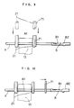
- the following problem also makes it difficult to automate the terminal inserting process. That is, in the terminal crimping step by crimping the wire crimping part B1 formed on the terminal B, the front end of the terminal B may be bent up or bent down(see double dot chain line in Fig. 19) from the crimped part at the bending point P.
- the terminal clamp 102 is designed to hold the wire crimped part B1 of the terminal B at the bending point P to insert on the basis of the holding position, a misalignment occurs between the front end B2 of the terminal B and the connector housing C, and also because of the narrow gap of the two, the terminal B may not be inserted into the connector housing C.
- a mechanism for inserting terminals fixed at ends of wires of a wiring harness into a connector housing wherein the wires have intermediate parts laid out on a lay-out board and have front end parts clamped by clamping means disposed outside of the layout board so that the terminals are directed outward of the lay-out board
- said mechanism comprising: terminal moving means for detaching the front end side of the wires from said clamping means and for moving the terminals so as to move them to a position inward of the lay-out board, housing holding means for holding the connector housing so that the terminal insertion ports in the connector housing confront the terminals which have been moved to a position inward of the lay-out board, and terminal inserting means for inserting the terminals into the terminal insertion ports by bringing the connector housing and the terminals opposite to the terminal insertion ports of the connector housing closer into the terminal insertion movable region.
- the invention is directed to a mechanism for inserting wired terminals for achieving the above object. More specifically, the present invention comprises a member for clamping the terminal to set the terminal in a state free to displace, and moving the terminal to return inward of the layout board. The invention also comprises a member for inserting the moved terminal finally into the connector housing. Hence, according to the present invention, because movement of the wire and terminal is allowed, it is not necessary to slacken or sag the wire in the intermediate part. Therefore, in the state of laying out the wire on the lay-out board, the terminals can be automatically inserted into the connector housing, which may also contribute to automation of fabrication process of wiring harness.
- the wire consecutive to the inserted terminal does not intersect the non-inserted terminal. Hence the conventional problem of interference of the wire for clamping the non-inserted terminal does not occur.
- the terminal chuck grips the front side of the terminal from the wire crimped part, the front end of the terminal can be securely inserted into the connector housing when the terminal is deformed in the terminal crimping step.
- the terminal can be positioned at a specific position, the terminal can be always gripped at the specific position by the terminal chuck.
- bending of the front end part of the wire or the terminal can be straightened, misalignment due to bending of wire front end part or the terminal can be prevented, so that defective terminal insertion can be prevented.
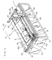
- Fig. 3 is a perspective view showing a manufacturing line of wiring harness using a mechanism for inserting wired terminals into a connector housing of the present invention.
- This manufacturing line is composed by arraying and coupling a specified number of modules in each section for each step.
- the manufacturing line comprises an automatic laying section 1, an automatic taping section 2, a stripping section 3, a stripping inspection section 4, a terminal crimping section 5, a crimping inspection section 6, a terminal inserting section 7, and a conduction inspection section 8, which are coupled in series in this order.
- the individual sections 1 to 8 are respectively realized by three automatic laying modules 1a, 1b, 1c, one automatic taping module 2a, two stripping modules 3a, 3b, one stripping inspection module 4a, four terminal crimping modules 5a, 5b, 5c, 5d, one crimping inspection module 6a, three terminal inserting modules 7a, 7b, 7c, and one conduction inspection module 8a.
- a lay-out board 9 is conveyed sequentially from the automatic laying section 1 to the conduction inspection section 8, section after section, so that the wiring harness is assembled on the lay-out board 9.
- the lay-out board 9 is a rectangular board, and multiple laying pins 9a are planted on its surface. As mentioned later, an intermediate part A2 of the wires A forming of the wiring harness are stopped by the laying pins 9a, in the automatic laying modules 1a, 1b, 1c of the automatic laying section 1, and the wires A are laid out on the lay-out board 9.
- the lay-out board 9 is supported by a moving stand 9b sequentially moving through the sections.
- clamp members 13 are mounted along one side of the lay-out board 9.
- the clamps 13 are disposed in a multiplicity along a side of the terminal inserting section 7 side in the confronting direction D2.
- Each clamp member 13 is intended to elastically clamp and hold each one of the front end parts A1 of the wires A, and is fitted to a long mounting frame 13g fixed at a specified position of the moving stand 9b.
- the clamp member 13 includes a pair of clamps 13b having a tapered end, and a U-shaped leaf spring 13c for biasing the pair of clamps 13b in the mutually approaching directions.
- Leaf spring 13c of each clamp member 13 is led into a groove 13h of the mounting frame 13g, and is fixed to the mounting frame 13g by a screw (not shown) driven through a penetration hole 13d formed in the bottom.
- the pair of clamps 13b are prevented from slipping out upward by pins 13f penetrating through holes 13e partitioned by the rounding surfaces formed on both clamps 13b and in the mounting frame 13g.
- a housing holding part 40 is further formed on the moving stand 9b.
- the housing holding part 40 includes a pair of slide guide bars 41 fixed and disposed at the upstream side and downstream side of the conveying direction D1 of the moving stand 9b, a long slide frame 42 slidably mounted between the slide guide bars 41, and a holding frame 43 for holding the connector housing C at the specified position of the slide frame 42.
- the housing holding part 40 is to hold the connector housing C in the state where the end surface of the connector housing C, in which the terminal insertion hole is formed is directed along the confronting direction D2.
- Slide frame 42 is set aside to the rear end side of the lay-out board 9 so as not to interfere the laying work as indicated by double dot chain line 42a in Fig. 2 in the step before the terminal inserting step.
- the lay-out board 9 When the lay-out board 9 is conveyed to the terminal inserting section 7, manually or automatically by the driving means not shown in the drawing, it is designed to slide to move to the front end side of the lay-out board 9, that is, in the insertion movable region of the terminal B.
- the housing holding part usable in the present invention is not particularly limited to the one shown in the foregoing embodiment provided that it is capable of holding the connector housing C in a specified state in the terminal inserting step.
- such mechanism may be provided in the terminal inserting section 7.
- the automatic laying section 1 is a section for automatically laying out a wire of a specific length on the lay-out board 9.
- wire groups 10 of specified types necessary for laying out are disposed, and wires of these wire groups 10 are taken into the automatic laying section 1 selectively, and laid on the lay-out board 9, and cut to specified length.
- the front ends A1 of the plurality of laid wires A are held by the clamp member 13 in a state of being projected from one side of the lay-out board 9 as shown in Fig. 4.
- Intermediate parts A2 of the wires A are stopped by the laying pins 9a on the lay-out board 9 as shown in Fig. 2.
- the wires A are taut between the clamp member 13 and laying pins 9a.
- the wires A laid on the lay-out board 9 contain various types depending on the circuit necessary in the wiring harness, ranging from thick size to thin size of the wires A.
- the lay-out board 9 on which wires are laid in the automatic laying section 1 are sent into the automatic taping section 2 coupled at the downstream side by the moving stand 9b, and the laid wires are taped at a specified position so that the wire bundle may not get loose.
- lay-out board 9 is then sent into the stripping section 3 coupled in series to the downstream side of the automatic taping section 2.
- the stripping section 3 the coating of the front ends of the wires A laid on the lay-out board 9 is stripped off.
- the lay-out board 9 after the stripping step is sent to the stripping inspection section 4 coupled to the downstream side of the stripping section 3.
- the stripping inspection section 4 for example, an inspection camera is installed, and striping of the front ends of the wires A is inspected, checking if the front ends of the stripped wires A are bent or loosened.
- the lay-out board 9 possessing such defective wires A may be automatically removed from the manufacturing line, or detection of the defective stripping of wires A may be indicated by a warning lamp or the like.
- the lay-out board 9 successfully passing through the stripping inspection section 4 is sent into the terminal crimping section 5.
- the terminal crimping section 5 four terminal crimping modules 5a, 5b, 5c, 5d are coupled in series.
- a conveying buffer section 11 is inserted between the second terminal crimping module 5b and the third terminal crimping module 5c.
- the lay-out board 9 sent from the second terminal crimping module 5b is folded back and conveyed into the conveying line and is sent out to the third terminal crimping module 5c.
- the conveyance of the lay-out board 9 is stopped for a predetermined time, and the timing for sending out the lay-out board 9 to the third terminal crimping module 5c is adjusted.
- terminals B (see Fig.2) are crimped to the exposed cores of the wires A after stripping the coated ends off in a state being outward of the lay-out board 9.
- the crimping inspection section 6 is coupled.
- an inspection camera is installed, and it is inspected whether the terminal B is crimped correctly to the front end of the wire A. It is also checked if the front end of the wire A to which the terminal B is crimped is bent abnormally or not.
- the lay-out board 9 having defectively crimped wires A may be removed automatically from the manufacturing line, or defective crimping may be indicated by a warning lamp or the like.
- the lay-out board 9 passing through the crimping inspection section 9 is sent to the terminal inserting section 7.
- three terminal inserting modules 7a, 7b, 7c are arranged in series.
- the terminal inserting modules 7a, 7b, 7c are realized by terminal inserting devices for automatically inserting the terminals B crimped to the front ends of the wires A into the connector housing C (see Fig. 2), and they comprise the principal block of the mechanism for inserting wired terminals into a connector housing together with the housing holding part 40 of the layout board 9 mentioned above.
- the first terminal inserting device 7a inserts terminals of group a into the connector housing C
- the second terminal inserting device 7b inserts terminals of group b into the connector housing C
- the third terminal inserting device 7c inserts terminals of group c into the connector housing C.
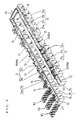
- the terminal inserting module 7a is mainly formed of a chuck part 20 including a wire chuck 21 for gripping the ends of the wires A held by the clamp member 13 and a terminal chuck 22 for gripping the terminals B crimped to the wires A, a terminal moving part 30 for moving the terminal so as to be opposite to the terminal insertion port of the connector housing C held by the housing holding part 40, by directing the front ends B2 (see Fig.
- terminal inserting part 50 for inserting the terminals B into specified positions of the connector housing C by bringing the chuck part 20 closer to the connector housing holding part 40
- terminal straightening part 60 for positioning and straightening the terminals B at specific positions, prior to gripping of the terminals B by the terminal chuck 22, and a wire straightening part 70 for straightening the bending of the ends by combing the ends of the wires A.
- the wire chuck 21 of the chuck part 20 is provided with plural pairs of chuck pawls 21a confronting each other, and is designed to clamp immobile plural positions of the wires A by the chuck pawl 21a.
- the chuck part 20 has an air chuck 23 for opening and closing the wire chuck 21, and the chuck pawls 21a are directly opened and closed by the air chuck 23.
- the chuck part 20 has an unclamping bar 27 for unclamping the wires A by the clamp member 13.
- the unclamping bar 27 is lowered by a cylinder not shown when gripping and picking up the wires A by the wire chuck 21 to get in between the clamps 13b of the clamp member 13, and the clamps 13 are opened so that the wires A may be picked up easily.
- the chuck part 20 is integrally mounted on a rotary frame 31 which rotates about the vertical shaft.
- the terminal chuck 22 is mounted elevatably on the rotary frame 31 through a first elevating frame 24.
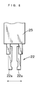
- the terminal chuck 22 is formed of a pair of chuck pawls 22a as shown in Fig. 6, and each chuck pawl 22a is directly fitted to an air chuck 25 fixed on the first elevating frame 24, and its opening and closing operations are effected by the air chuck 25.
- the terminal chuck 22 is to grip the front B2 side of the wire crimping part or press-connecting part B1 of the terminal B (Fig. 12), and is elevated or lowered by a cylinder 26 described later through the first elevating frame 24.
- the terminal moving part 30 includes a second elevating frame 32 whose front end side is extended in the horizontal direction, a rotary actuator 33 mounted on the horizontal part of the second elevating frame 32, the rotary frame 31 being rotatably mounted on the second elevating frame 32 through a bearing 31a, a pair of pulleys 33a for transmitting the driving force of the rotary actuator 33 to the rotary frame 31, and a timing belt 34 applied between the both pulleys 33a, in which the rotary frame 31 can be alternately rotated in the clockwise direction and counterclockwise direction by 180 degrees from the state indicated by solid line in Fig. 1 to the state indicated by double dot chain line.
- the second elevating frame 32 is slidably mounted on an elevating guide 35 extending in the vertical direction, and is driven vertically by an actuator not shown in the drawing.
- the position control of the second elevating frame 32 is effected accurately by using, for example, a linear scale.
- a cylinder 26 is fixed for elevating and lowering the first elevating frame 24.
- the terminal inserting part 50 includes a post 51 for movably supporting the elevating guide 35 in the confronting direction D2, a first drive mechanism (not shown) for moving the elevating guide 35, and a second drive mechanism (not shown) for moving the post 51 along a slide rail 53 provided parallel to the conveying direction D1 of the lay-out board 9.
- Each drive mechanism is formed of a slide mechanism combining, for example, a pulse motor and a ball screw, and is controlled by a control part 52 described later, so that each member may be moved to the position capable of accurately gripping the wires A and terminals B by the chuck part 20, and the position for accurately inserting the terminals B to the connector housing C.
- the terminal straightening part 60 is provided elevatably immediately beneath the terminals B and includes a locate chuck 61 which receives the front ends B2 of the terminals B and grips the front ends B2 in that state, and a terminal holder 62 for holding down from above the terminals B received by the locate chuck 61, which is driven vertically by a cylinder 63 mounted on the first elevating frame 24.
- the terminal straightening part 60 is to position the terminals B1 in a specified position, and further straighten the terminals, so that the terminal chuck 22 can grip the terminals B always in the specified position.
- the terminal straightening part 60 is integrally mounted on the post 51 by a frame member not shown, so as to be moved together with the post 51.
- the wire straightening part 70 includes a combing member 71 adjacent to the wire chuck 21, and a cylinder 72 for moving the combing member from the clamp member 13 side to the terminals B.
- the combing member 71 is so assembled as to be movable to the terminals B relative to the wire chuck 21, and is coupled with the cylinder 72 through a coupling mechanism not shown in the drawing.
- the combing member 71 has a pair of straightening pawls 71a for slidably gripping the wires A as shown in Fig. 7.
- the pair of straightening pawls 71a are opened and closed in cooperation with the wire chuck 21 by the air chuck 23 for opening and closing the wire chuck 21.
- the pair of straightening pawls 71a have protrusions 71c projecting in the state mutually deviated in the longitudinal direction of the wires A, thereby combing the wires A effectively.
- the control part 52 is composed of microcomputer and other electric parts, and is designed to drive and control the members of the corresponding modules.
- the lay-out board 9 When the lay-out board 9 is conveyed to the specified position of the terminal inserting section 7 by the moving stand 9b, the lay-out board 9 stands still at the position indicated in Fig. 2.
- the post 51 is moved along the slide rail 53 to the position corresponding to the wires A held by the specified clamp member 13, and the terminals B crimped at the end of the wires A.
- the slide frame 42 of the housing holding part 40 mounted on the moving stand 9b of the lay-out board 9 is driven in the specified method, and the connector housing C held in the holding member 43 is preliminarily moved into the insertion movable region of the terminals.
- the second elevating frame 32 is lowered along the elevating guide 35, and the wire chuck 21 and combing member 71 are lowered to the position capable of gripping the wires A with the pawls 21a, 71a being open (see Fig. 9).
- the air chuck 23 is driven, and the pawls 21a, 71a of the wire chuck 21 and combing member 71 respectively are closed simultaneously, thereby gripping the wires A.
- the cylinder 72 is driven, and the combing member 71 is moved toward the front end of the wires A to comb the wires A, thereby straightening the bending of the wires A (see Fig. 10).
- the locate chuck 61 of the terminal straightening part 60 When the locate chuck 61 of the terminal straightening part 60 is elevated, the lower surface of the terminals B is received by the locate chuck 61, and positioning is effected (see Fig. 11). Furthermore, with the terminals B being received by the locate chuck 61, the cylinder 26 is driven, and the terminal chuck 22 is lowered, with the chuck pawls 22a being open (see Fig. 12).
- the cylinder 63 is driven, the terminal holder 62 is lowered, and the front ends B2 of the terminals B are clamped between the terminal holder 62 and the locate chuck 61.
- the terminals B are positioned in the vertical direction (see Fig. 13).
- the locate chuck 61 is closed, and the terminals B are positioned and straightened in the lateral direction, then the air chuck 23 is driven, the terminal chuck 22 is closed, and the wires A are gripped.
- the combing member 71 returns to the wire chuck 21 side (see Fig. 14), and the locate chuck 61 is opened at the same time to lower to the home position.
- the second elevating frame 32 is raised, and the chuck part 20 picks up the terminals B and wires A (see Fig. 15).
- the unclamping bar 27 is lowered to open the clamp member 13, thereby making it ready to pick up the front ends A1 of the wires A.
- the front ends A1 of the wires A are released from the clamp member 13, and set free.
- the rotary actuator 33 is driven, and the rotary frame 31 is turned by 180 degrees (double dot chain line in Fig. 1, and see also Fig. 16).
- the terminals B are returned inward of the lay-out board 9.
- the front ends B2 of the terminals B confront the specified connector housing C waiting preliminarily in the insertion movable region of the terminals B.
- the height of the terminals B may be set precisely opposite to the terminal insertion port of the connector housing C held in the housing holding part 40.
- the chuck part 20 By driving the terminal inserting part 50, the chuck part 20 is moved to the connector housing C through the elevating guide 35, second elevating frame 32, rotary frame 31 and others, and the terminals b are inserted into the connector housing C (see Fig. 17).
- the terminal chuck 22 is opened to cancel the gripping state of the terminals B, and the cylinder 26 is driven by the control part 52, and the terminal chuck 22 and terminal holder 62 are set aside upward, while the wire chuck 21 is further moved closer to the connector housing C side by the terminal inserting part 50, and the terminals B are inserted into the specified position of the connector housing C (see Fig. 18).
- the terminal B can be inserted into the connector housing C.
- the ends of the wires A held by the clamp member 13 are inverted together with the terminals B, and inserted into the connector housing C, and therefore it is possible to insert the terminals B in the state of being laid out on the lay-out board 9, without having to slacken or sag the intermediate part of the wires A for allowing movement to the connector housing C side.
- terminal chuck 22 grips the front end B2 side of the wire crimped part B1 of the terminals B, if the terminal is deformed in the prior step of terminal crimping process, such terminal B can be securely inserted into the connector housing C.
- the terminals B may be always gripped at high positioning precision by the terminal chuck 22. Accordingly. the terminals B can be securely inserted into the connector housing C.
- terminals B are prevented from colliding against the specified part in the connector 5 housing C. Besides, it is easier to grip the terminal B by the locate chuck 61, further enhancing the positioning precision of the terminals B.
- the terminal inserting module is not limited to the embodiment, and the terminal inserting part 50 is not particularly defined provided that it is capable of moving the housing holding part 40 side to the direction of the terminal chuck 22 and wire chuck 21.
- the lay-out board 9 passing through the terminal inserting section 7 is conveyed to the conduction inspection section 8.
- an inspection coupler is connected to the connector housing C in which terminals B are inserted, and the conduction of the laid wires A is inspected.
- any lay-out board 9 having a defective conduction wire A is found, such lay-out board 9 may be automatically removed from the manufacturing line, or the detection of defective conduction may be alarmed by any means.
- the lay-out board 9 successfully passing through the conduction inspection section 8 is conveyed to the buffer section 12.
- the lay-out board 9 sent out to the buffer section 12 is regarded as being finished in the processing in this manufacturing line, and is forwarded to the next manufacturing process.
Applications Claiming Priority (2)
| Application Number | Priority Date | Filing Date | Title |
|---|---|---|---|
| JP234793/92 | 1992-09-02 | ||
| JP4234793A JP2706408B2 (ja) | 1992-09-02 | 1992-09-02 | 端子挿入装置 |
Publications (3)
| Publication Number | Publication Date |
|---|---|
| EP0586252A2 EP0586252A2 (en) | 1994-03-09 |
| EP0586252A3 EP0586252A3 (en) | 1994-08-24 |
| EP0586252B1 true EP0586252B1 (en) | 1995-11-29 |
Family
ID=16976483
Family Applications (1)
| Application Number | Title | Priority Date | Filing Date |
|---|---|---|---|
| EP93306955A Expired - Lifetime EP0586252B1 (en) | 1992-09-02 | 1993-09-02 | Mechanism for inserting wired terminals into a connector housing |
Country Status (4)
| Country | Link |
|---|---|
| US (1) | US5414925A (ja) |
| EP (1) | EP0586252B1 (ja) |
| JP (1) | JP2706408B2 (ja) |
| DE (1) | DE69300906T2 (ja) |
Families Citing this family (26)
| Publication number | Priority date | Publication date | Assignee | Title |
|---|---|---|---|---|
| JP2836725B2 (ja) * | 1993-11-29 | 1998-12-14 | 矢崎総業株式会社 | 端子挿入方法及び端子挿入装置 |
| JP3097806B2 (ja) * | 1994-10-07 | 2000-10-10 | 矢崎総業株式会社 | 端子挿入装置 |
| CH689288A5 (de) * | 1994-10-21 | 1999-01-29 | Komax Holding Ag | Verfahren und Vorrichtung zum Bestuecken von Steckergehaeusen. |
| JP3019737B2 (ja) * | 1994-12-08 | 2000-03-13 | 住友電装株式会社 | 端子挿入装置 |
| JP3053434B2 (ja) * | 1995-07-10 | 2000-06-19 | 株式会社小寺電子製作所 | 加工線材の挿着装置 |
| JPH09129348A (ja) * | 1995-11-07 | 1997-05-16 | Yazaki Corp | 端子挿入方法及び端子挿入装置 |
| JP3301004B2 (ja) * | 1995-07-26 | 2002-07-15 | 矢崎総業株式会社 | 端子挿入装置と端子姿勢矯正装置及び端子姿勢矯正方法並びに端子挿入方法 |
| JP3301006B2 (ja) * | 1995-11-07 | 2002-07-15 | 矢崎総業株式会社 | 端子挿入方法 |
| JP3301007B2 (ja) * | 1995-11-10 | 2002-07-15 | 矢崎総業株式会社 | 端子挿入方法 |
| JPH09134771A (ja) * | 1995-11-10 | 1997-05-20 | Yazaki Corp | 特殊配列ハウジングへの端子挿入方法 |
| US5806176A (en) * | 1996-02-05 | 1998-09-15 | Raychem Corporation | Insertion tool and method of use |
| US6612026B1 (en) * | 1999-05-24 | 2003-09-02 | Sumitomo Wiring Systems, Ltd. | Process for mounting terminals with electric wires in cavities of connector housings |
| FR2880464A1 (fr) | 2004-12-30 | 2006-07-07 | Eurocopter France | Outil, procede et dispositif de fabrication de harnais electriques |
| FR2880465A1 (fr) * | 2004-12-30 | 2006-07-07 | Eurocopter France | Procede et dispositif de fabrication de harnais electriques |
| ITPD20050297A1 (it) * | 2005-10-12 | 2007-04-13 | K M I Trade Srl | Attrezzatura per la realizzazione di cablaggi elettrici |
| EP2779328B1 (de) | 2012-04-20 | 2017-03-08 | Schleuniger Holding AG | Verfahren und Vorrichtung zur Herstellung eines Steckers |
| JP6072451B2 (ja) * | 2012-07-19 | 2017-02-01 | 矢崎総業株式会社 | ハウジング反転装置とそれを用いた端子挿入方法 |
| US20150113804A1 (en) * | 2013-10-29 | 2015-04-30 | General Electric Company | Wire strip and crimp tool |
| WO2016088088A1 (de) | 2014-12-04 | 2016-06-09 | Schleuniger Holding Ag | Verfahren zum anbringen eines bauteiles am ende eines abisolierten kabels |
| US9819134B2 (en) | 2015-02-27 | 2017-11-14 | General Electric Company | Tool for stripping and crimping a wire |
| CN106505399B (zh) * | 2015-09-07 | 2019-06-07 | 泰科电子(上海)有限公司 | 装配系统和装配方法 |
| CN109802275B (zh) * | 2018-02-09 | 2023-10-17 | 深圳市中海通机器人有限公司 | 刺芯线端子胶套自动装配系统 |
| CN108429113B (zh) * | 2018-05-14 | 2023-11-21 | 深圳市华惠连接器有限公司 | 电连接器接触件护套自动装配设备 |
| JP7111659B2 (ja) * | 2019-06-28 | 2022-08-02 | 矢崎総業株式会社 | 端子の外観検査装置 |
| EP3876370A1 (de) * | 2020-03-06 | 2021-09-08 | Andreas Ripploh | Aufnahmevorrichtung für vorkonfektionierte elektrische leiter |
| CN113258405B (zh) * | 2021-05-10 | 2022-06-21 | 东莞市新波特电气有限公司 | 一种线束组装设备的插线机构 |
Family Cites Families (13)
| Publication number | Priority date | Publication date | Assignee | Title |
|---|---|---|---|---|
| GB1556036A (en) * | 1975-10-30 | 1979-11-21 | Yazaki Corp | Process and apparatus for producing a wire-harness |
| US4055889A (en) * | 1976-02-18 | 1977-11-01 | Molex Incorporated | Connector harness assembly machine |
| GB2109644B (en) * | 1978-09-29 | 1983-10-12 | Yazaki Corp | Wiring head for use in the manufacture of a wire harness |
| US4520966A (en) * | 1983-10-07 | 1985-06-04 | The Boeing Company | Wire canister for a robotic wire harness assembly system |
| JPS6161489A (ja) * | 1984-09-03 | 1986-03-29 | キヤノン電子株式会社 | プリント配線板の製造方法 |
| EP0226665A1 (en) * | 1985-12-18 | 1987-07-01 | Elmecon, Consulting Associates B.V. | Device for assembling connector housings |
| US4779334A (en) * | 1988-02-10 | 1988-10-25 | Amp Incorporated | Apparatus for inserting terminals on the ends of wires into cavities in an electrical connector |
| ES2014657A6 (es) * | 1988-06-13 | 1990-07-16 | Yazaki Corp | Procedimiento y aparato para insertar automaticamente extremis de alambres con elementos terminales en un alojamiento conector. |
| JPH01313872A (ja) * | 1988-06-13 | 1989-12-19 | Yazaki Corp | 電線付端子のコネクタハウジングへの挿入方法及び装置 |
| JPH0736352B2 (ja) * | 1990-03-23 | 1995-04-19 | 住友電装株式会社 | 電線付端子のコネクタハウジングへの挿入方法および装置 |
| DE4010349A1 (de) * | 1990-03-28 | 1991-10-02 | Siemens Ag | Steckmodul fuer eine kabelkonfektioniereinrichtung |
| US4970777A (en) * | 1990-04-20 | 1990-11-20 | Amp Incorporated | Apparatus for connector block loading of electrical leads |
| US4967470A (en) * | 1990-04-20 | 1990-11-06 | Amp Incorporated | Alignment apparatus for positioning a connector housing during wire insertion |
-
1992
- 1992-09-02 JP JP4234793A patent/JP2706408B2/ja not_active Expired - Lifetime
-
1993
- 1993-08-31 US US08/114,044 patent/US5414925A/en not_active Expired - Fee Related
- 1993-09-02 EP EP93306955A patent/EP0586252B1/en not_active Expired - Lifetime
- 1993-09-02 DE DE69300906T patent/DE69300906T2/de not_active Expired - Fee Related
Also Published As
| Publication number | Publication date |
|---|---|
| EP0586252A3 (en) | 1994-08-24 |
| DE69300906D1 (de) | 1996-01-11 |
| JPH0684577A (ja) | 1994-03-25 |
| DE69300906T2 (de) | 1996-04-11 |
| EP0586252A2 (en) | 1994-03-09 |
| US5414925A (en) | 1995-05-16 |
| JP2706408B2 (ja) | 1998-01-28 |
Similar Documents
| Publication | Publication Date | Title |
|---|---|---|
| EP0586252B1 (en) | Mechanism for inserting wired terminals into a connector housing | |
| US4653159A (en) | Flexible automated manufacturing system | |
| US4055889A (en) | Connector harness assembly machine | |
| US6877208B2 (en) | Apparatus for connecting a terminal-connected wire to a connector | |
| US5606909A (en) | Apparatus for winding tape | |
| EP2418658B1 (en) | Electric wire terminal treatment device and electric wire terminal treatment method | |
| EP0667658B1 (en) | Device and method for measuring crimp height | |
| US6961996B2 (en) | Method for installing cable ends in plug housings | |
| US4976294A (en) | Method and apparatus for making specified-length wires for wire harness | |
| EP0614252B1 (en) | Connector housing feeding mechanism | |
| CA1257465A (en) | Flexible automated manufacturing system | |
| US5581873A (en) | Temporary holding member for a wiring assembly manufacturing apparatus | |
| EP0181780A2 (en) | Wire preparation system | |
| JP3069252B2 (ja) | 端子挿入装置及びこれに用いる端子挿入機構 | |
| US5933932A (en) | Apparatus for making electrical harness | |
| JP3095306B2 (ja) | 端子挿入装置 | |
| JP2888707B2 (ja) | 端子挿入ガイド装置 | |
| JPH0555994B2 (ja) | ||
| JPH0366790B2 (ja) | ||
| JP2661726B2 (ja) | ケーブル心線接続装置 | |
| JPS63200416A (ja) | ワイヤ−ハ−ネス自動製造装置 | |
| FI89124C (fi) | Foerfarande och anordning foer att styra en monteringsmaskin foer kabelledarknippen | |
| JPS6345780A (ja) | 端子付電線の插入装置 | |
| JPH0555992B2 (ja) | ||
| JPH11260166A (ja) | 自動電線処理装置 |
Legal Events
| Date | Code | Title | Description |
|---|---|---|---|
| PUAI | Public reference made under article 153(3) epc to a published international application that has entered the european phase |
Free format text: ORIGINAL CODE: 0009012 |
|
| AK | Designated contracting states |
Kind code of ref document: A2 Designated state(s): DE GB |
|
| PUAL | Search report despatched |
Free format text: ORIGINAL CODE: 0009013 |
|
| AK | Designated contracting states |
Kind code of ref document: A3 Designated state(s): DE GB |
|
| 17P | Request for examination filed |
Effective date: 19941004 |
|
| 17Q | First examination report despatched |
Effective date: 19950209 |
|
| GRAA | (expected) grant |
Free format text: ORIGINAL CODE: 0009210 |
|
| AK | Designated contracting states |
Kind code of ref document: B1 Designated state(s): DE GB |
|
| REF | Corresponds to: |
Ref document number: 69300906 Country of ref document: DE Date of ref document: 19960111 |
|
| PLBE | No opposition filed within time limit |
Free format text: ORIGINAL CODE: 0009261 |
|
| STAA | Information on the status of an ep patent application or granted ep patent |
Free format text: STATUS: NO OPPOSITION FILED WITHIN TIME LIMIT |
|
| 26N | No opposition filed | ||
| PGFP | Annual fee paid to national office [announced via postgrant information from national office to epo] |
Ref country code: GB Payment date: 19990901 Year of fee payment: 7 |
|
| PGFP | Annual fee paid to national office [announced via postgrant information from national office to epo] |
Ref country code: DE Payment date: 19990906 Year of fee payment: 7 |
|
| PG25 | Lapsed in a contracting state [announced via postgrant information from national office to epo] |
Ref country code: GB Free format text: LAPSE BECAUSE OF NON-PAYMENT OF DUE FEES Effective date: 20000902 |
|
| GBPC | Gb: european patent ceased through non-payment of renewal fee |
Effective date: 20000902 |
|
| PG25 | Lapsed in a contracting state [announced via postgrant information from national office to epo] |
Ref country code: DE Free format text: LAPSE BECAUSE OF NON-PAYMENT OF DUE FEES Effective date: 20010601 |