EP0579843A1 - Phasenänderungsvorrichtung und diese gebrauchendes optisches abtastgerät für eine magneto-optische speicherung - Google Patents
Phasenänderungsvorrichtung und diese gebrauchendes optisches abtastgerät für eine magneto-optische speicherung Download PDFInfo
- Publication number
- EP0579843A1 EP0579843A1 EP93903326A EP93903326A EP0579843A1 EP 0579843 A1 EP0579843 A1 EP 0579843A1 EP 93903326 A EP93903326 A EP 93903326A EP 93903326 A EP93903326 A EP 93903326A EP 0579843 A1 EP0579843 A1 EP 0579843A1
- Authority
- EP
- European Patent Office
- Prior art keywords
- magneto
- light
- pickup apparatus
- optical
- optical pickup
- Prior art date
- Legal status (The legal status is an assumption and is not a legal conclusion. Google has not performed a legal analysis and makes no representation as to the accuracy of the status listed.)
- Granted
Links
Images


Classifications
-
- G—PHYSICS
- G11—INFORMATION STORAGE
- G11B—INFORMATION STORAGE BASED ON RELATIVE MOVEMENT BETWEEN RECORD CARRIER AND TRANSDUCER
- G11B7/00—Recording or reproducing by optical means, e.g. recording using a thermal beam of optical radiation by modifying optical properties or the physical structure, reproducing using an optical beam at lower power by sensing optical properties; Record carriers therefor
- G11B7/12—Heads, e.g. forming of the optical beam spot or modulation of the optical beam
- G11B7/13—Optical detectors therefor
- G11B7/131—Arrangement of detectors in a multiple array
-
- G—PHYSICS
- G02—OPTICS
- G02B—OPTICAL ELEMENTS, SYSTEMS OR APPARATUS
- G02B5/00—Optical elements other than lenses
- G02B5/04—Prisms
-
- G—PHYSICS
- G02—OPTICS
- G02B—OPTICAL ELEMENTS, SYSTEMS OR APPARATUS
- G02B5/00—Optical elements other than lenses
- G02B5/30—Polarising elements
- G02B5/3083—Birefringent or phase retarding elements
-
- G—PHYSICS
- G11—INFORMATION STORAGE
- G11B—INFORMATION STORAGE BASED ON RELATIVE MOVEMENT BETWEEN RECORD CARRIER AND TRANSDUCER
- G11B11/00—Recording on or reproducing from the same record carrier wherein for these two operations the methods are covered by different main groups of groups G11B3/00 - G11B7/00 or by different subgroups of group G11B9/00; Record carriers therefor
- G11B11/10—Recording on or reproducing from the same record carrier wherein for these two operations the methods are covered by different main groups of groups G11B3/00 - G11B7/00 or by different subgroups of group G11B9/00; Record carriers therefor using recording by magnetic means or other means for magnetisation or demagnetisation of a record carrier, e.g. light induced spin magnetisation; Demagnetisation by thermal or stress means in the presence or not of an orienting magnetic field
- G11B11/105—Recording on or reproducing from the same record carrier wherein for these two operations the methods are covered by different main groups of groups G11B3/00 - G11B7/00 or by different subgroups of group G11B9/00; Record carriers therefor using recording by magnetic means or other means for magnetisation or demagnetisation of a record carrier, e.g. light induced spin magnetisation; Demagnetisation by thermal or stress means in the presence or not of an orienting magnetic field using a beam of light or a magnetic field for recording by change of magnetisation and a beam of light for reproducing, i.e. magneto-optical, e.g. light-induced thermomagnetic recording, spin magnetisation recording, Kerr or Faraday effect reproducing
- G11B11/10532—Heads
- G11B11/10541—Heads for reproducing
- G11B11/10543—Heads for reproducing using optical beam of radiation
-
- G—PHYSICS
- G11—INFORMATION STORAGE
- G11B—INFORMATION STORAGE BASED ON RELATIVE MOVEMENT BETWEEN RECORD CARRIER AND TRANSDUCER
- G11B7/00—Recording or reproducing by optical means, e.g. recording using a thermal beam of optical radiation by modifying optical properties or the physical structure, reproducing using an optical beam at lower power by sensing optical properties; Record carriers therefor
- G11B7/12—Heads, e.g. forming of the optical beam spot or modulation of the optical beam
- G11B7/123—Integrated head arrangements, e.g. with source and detectors mounted on the same substrate
-
- G—PHYSICS
- G11—INFORMATION STORAGE
- G11B—INFORMATION STORAGE BASED ON RELATIVE MOVEMENT BETWEEN RECORD CARRIER AND TRANSDUCER
- G11B7/00—Recording or reproducing by optical means, e.g. recording using a thermal beam of optical radiation by modifying optical properties or the physical structure, reproducing using an optical beam at lower power by sensing optical properties; Record carriers therefor
- G11B7/12—Heads, e.g. forming of the optical beam spot or modulation of the optical beam
- G11B7/135—Means for guiding the beam from the source to the record carrier or from the record carrier to the detector
- G11B7/1356—Double or multiple prisms, i.e. having two or more prisms in cooperation
-
- G—PHYSICS
- G11—INFORMATION STORAGE
- G11B—INFORMATION STORAGE BASED ON RELATIVE MOVEMENT BETWEEN RECORD CARRIER AND TRANSDUCER
- G11B7/00—Recording or reproducing by optical means, e.g. recording using a thermal beam of optical radiation by modifying optical properties or the physical structure, reproducing using an optical beam at lower power by sensing optical properties; Record carriers therefor
- G11B7/12—Heads, e.g. forming of the optical beam spot or modulation of the optical beam
- G11B7/135—Means for guiding the beam from the source to the record carrier or from the record carrier to the detector
- G11B7/1359—Single prisms
-
- G—PHYSICS
- G11—INFORMATION STORAGE
- G11B—INFORMATION STORAGE BASED ON RELATIVE MOVEMENT BETWEEN RECORD CARRIER AND TRANSDUCER
- G11B7/00—Recording or reproducing by optical means, e.g. recording using a thermal beam of optical radiation by modifying optical properties or the physical structure, reproducing using an optical beam at lower power by sensing optical properties; Record carriers therefor
- G11B7/12—Heads, e.g. forming of the optical beam spot or modulation of the optical beam
- G11B7/135—Means for guiding the beam from the source to the record carrier or from the record carrier to the detector
- G11B7/1365—Separate or integrated refractive elements, e.g. wave plates
- G11B7/1367—Stepped phase plates
Definitions
- the present invention relates to a phase changing apparatus such as a phase delay type prism, combination optical rotating plate, etc. and to an optical pickup apparatus used for an optical disk device using the phase changing apparatus more particularly relates to an optical pickup apparatus for a magneto-optic storage device suitable for reproduction of information recorded in a magneto-optic recording medium (MO) and a phase difference generation apparatus used in this optical pickup apparatus etc.
- a phase changing apparatus such as a phase delay type prism, combination optical rotating plate, etc.
- an optical pickup apparatus used for an optical disk device using the phase changing apparatus more particularly relates to an optical pickup apparatus for a magneto-optic storage device suitable for reproduction of information recorded in a magneto-optic recording medium (MO) and a phase difference generation apparatus used in this optical pickup apparatus etc.
- MO magneto-optic recording medium
- an optical pickup apparatus used for a magneto-optic storage device for reproducing information recorded in a magneto-optic recording medium for example, a magneto-optic disk
- a linear polarized laser beam is irradiated on a recording surface of the magneto-optic disk, and the information recorded as a magnetization direction on the recording surface is converted to a rotation of the polarization plane by the electrooptic Kerr effect or the Faraday effect, which are interactions between light and magnetization, and then detected.
- Such an optical pickup apparatus for a magneto-optic storage device differs from an optical pickup apparatus which reproduces information from a compact disk (CD) such as an optical disk used only for reproduction, a write-once optical disk, a phase change type optical disk, etc., that is, an optical pickup apparatus for an optical recording and reproduction apparatus which detects the change of the amount of reflection light based on the presence/absence of pits.
- CD compact disk
- an optical pickup apparatus for an optical recording and reproduction apparatus which detects the change of the amount of reflection light based on the presence/absence of pits.
- a polarization beam splitter has been known as an optical element which can exhibit desired characteristics even if it is placed in converged light, but it has been thought to be difficult to separate a MO signal using a polarization beam splitter. Nevertheless, several methods mentioned below have been known.
- a conventional optical pickup apparatus for a magneto-optic storage device is constituted by for example a semiconductor laser; a collimate lens which collimates the light emitted from this semiconductor laser to a parallel beam; an objective lens which converges the emitted light collimated to the parallel beam by this collimate lens and irradiates the same on the recording surface of the magneto-optic disk; a polarization beam splitter which is arranged between the semiconductor laser and the objective lens and separates a part of the reflection light reflected at the recording surface of the magneto-optic disk (hereinafter referred to as the first polarization beam splitter); a light detector which detects a part of the reflection light split by this first polarization beam splitter; a photoelectric conversion element which detects the level of the light transmitted through this light detector (hereinafter referred to as a detector), etc.
- the emitted light from the semiconductor laser is converged and irradiated on the recording surface of the magneto-optic disk, a part of the reflection light reflected at this recording surface is split, and the level of the component having a predetermined polarization plane in a part of the split reflection light, that is, a predetermined light vibration plane is detected, and the information recorded in the magneto-optic disk is detected from that component.
- an optical pickup apparatus for a magneto-optic storage device using a 1/2-wavelength plate and a second polarization beam splitter in place of the above-described light detector has been proposed.
- the components of the reflection light split by the first polarization beam splitter that is, the so-called P wave component, i.e., the component having the same plane of vibration as that of the emitted light from the laser, and the S wave component, which has a vibration direction orthogonal to this P wave component, are split by the 1/2-wavelength plate and the second polarization beam splitter in place of the light detector, the levels of the split orthogonal S wave component and P wave component are detected by the two detectors, a level difference between them is detected at a differential amplifier, and the recorded information is detected by the differentiation method.
- the S wave component of the laser beam split from the reflection light at the first polarization beam splitter is a magneto-optic signal (hereinafter referred to as an MO signal)
- the reflectance with respect to the S wave of the first polarization beam splitter is desirably set to 100 percent, but the reflectance with respect to the P wave component is still set so that the amount of light incident upon the detector and a shot noise of the detector or a noise due to the birefringence of the disk substrate or the like are well balanced, and therefore there is a problem in that the coupling efficiency is low in comparison with an optical pickup apparatus used only for reproduction etc.
- the laser beam split at the first polarization beam splitter is split into two components by the second polarization beam splitter, and therefore it is necessary to establish the light path for it.
- the dimensions for the establishment of the light path are large, and thus the reduction of size of the optical pickup apparatus is difficult.
- the coating for the polarization-splitting of the polarization beam splitter is difficult.
- the coating technique for reducing the phase difference with respect to the P wave and S wave is very difficult, and therefore generally it is necessary to arrange the first polarization beam splitter in the parallel beam, and a collimate lens is always necessary.
- optical pickup apparatus for a magneto-optic storage device not using a 1/2-wavelength plate and a second polarization beam splitter, but using a Wollaston prism in place of the above-described light detector.
- this optical pickup apparatus for a magneto-optic storage device also meets with a similar problem to the one which occurred in the optical pickup apparatus for a magneto-optic storage device using a 1/2-wavelength plate and a second polarization beam splitter.
- An object of the present invention is to achieve a reduction of size of a magneto-optic storage device reproducing information recorded in a magneto-optic recording medium such as a magneto-optic disk by reducing the number of parts of the optical pickup apparatus.
- Another object of the present invention is to provide an optical pickup apparatus for a magneto-optic storage device having a high coupling efficiency.
- a further object of the present invention is to provide a phase changing apparatus which can be suitably used for such an optical pickup apparatus for a magneto-optic storage device.
- Still another object of the present invention is to provide a phase changing apparatus for changing the phase of the light which can be suitably applied for various purposes, not being restricted to an optical pickup apparatus for a magneto-optic storage device.
- phase change means such as a 1/2-wavelength plate, a phase difference generation prism, a combination optical rotating plate, etc. is used.
- an optical pickup apparatus having a laser beam source, a polarization beam splitter, an objective lens, and a light detection element, which are arranged along a light axis, wherein an emitted light from the aforesaid laser beam source is emitted as converged light to the recording surface of the magneto-optic recording medium and in which a predetermined polarization light component in the reflection light from the recording surface of the magneto-optic recording medium is split by the aforesaid polarization beam splitter and taken out by the aforesaid light detection element, characterized in that: a phase change means for changing the phase of the light passing through one side of the aforesaid light axis and the phase of the light passing through the other side of the aforesaid light axis exactly at a predetermined angle is provided between the aforesaid polarization beam splitter and the aforesaid objective lens; and the light changed by the afores
- phase change means use can be made of a 1/2-wavelength plate which has two division regions obtained by division into at least two sections facing each other across the aforesaid light axis as a boundary on a plane orthogonal to the aforesaid light axis, has planes of vibration at predetermined angles with respect to the aforesaid light axis, and has C axes with respect to the aforesaid light axes as a C1 axis and C2 axis and which is arranged so as to allow the emitted light from the aforesaid laser beam source to pass through one division region and allow the reflection light reflected at the recording surface of the aforesaid magneto-optic recording medium to pass through another division region.
- the aforesaid light detection element is divided into four regions corresponding to the division of the aforesaid 1/2-wavelength plate with the aforesaid light axis as the center, preferably is divided into four so as not to have a detection portion in a portion corresponding to the aforesaid light axis, and detects the magneto-optic (MO) recording signal recorded in the aforesaid magneto-optic recording medium from the detection signals of the four division regions.
- MO magneto-optic
- the aforesaid 1/2-wavelength plate is face-adhered to the surface of the aforesaid objective lens side of the aforesaid polarization beam splitter.
- a light detection element having a large light receiving surface area is secured to the plane of the aforesaid polarization beam splitter orthogonal to the surface to which the aforesaid 1/2-wavelength plate is face-adhered.
- a hologram laser unit equipped with a focus error detection function is used as the aforesaid laser beam source.
- a polarization beam splitter having a phase difference relative to the polarized P wave component and the polarized S wave component of almost 0° is used as the aforesaid polarization beam splitter.
- a light detection element such as an avalanche photodiode (APD) in which the angles of the planes of vibration in the aforesaid two division regions of the aforesaid 1/2-wavelength plate are made different and the light receiving plane is not divided as the aforesaid light detection element is used.
- APD avalanche photodiode
- the optical pickup apparatus for the magneto-optic storage device is preferably provided with a microprism which has a first parallel plane having a plane with a predetermined inclination angle and reflecting light incident through that plane at a first position and a second parallel plane parallel to the aforesaid first parallel plane at which the light reflected at that first position is further reflected and is constituted so that the light reflected at the second parallel plane is further reflected to a second position of the first parallel plane; two light detection elements which are provided corresponding to the aforesaid first portion and second position of the aforesaid first parallel plane, each of which has three division regions obtained by division into three, i.e., a center portion and the two side portions thereof; a first mirror using a laser coupler integrally constituting a laser beam source provided so as to face the aforesaid inclined plane of the aforesaid microprism on the same semiconductor substrate and provided on the side at which the light from the aforesaid laser beam source incident upon the
- the optical pickup apparatus for the magneto-optic storage device further includes two differential amplifiers which detect the differential signal from the three division regions of the aforesaid two light detection elements and a third differential amplifier which further differentially amplifies the output signal of these differential amplifiers.
- phase difference generation device which has a 45 degree prism and has phase difference generation film which is coated on the reflection surface of the 45 degree prism, has a plurality of division regions which are obtained by division into at least two on a plane orthogonal to the aforesaid light axis and have mutually predetermined phase difference characteristics and which is arranged so that the emitted light from the aforesaid laser beam source passes through one division region, and the reflection light reflected at the recording surface of the aforesaid magneto-optic recording medium passes through another division region.
- the film thickness of the aforesaid phase difference generation film may be adjusted to change the aforesaid phase difference.
- the number of the aforesaid division regions may be two, which two division regions may be obtained by division symmetrically using a diagonal line of the aforesaid reflection plane as the center, symmetrically in the vertical direction of the reflection plane, or symmetrically in a horizontal direction of the reflection plane.
- phase change means use can be made of a combination optical rotating plate which has division regions obtained by division into at least two on a plane orthogonal to the aforesaid light axis, which passes the emitted light from the aforesaid laser beam source through one side region while optical rotating the same right or optical rotating the same left exactly at a predetermined angle and passes the reflection light reflected at the recording surface of the above-described magneto-optic recording medium through the other side region while optical rotating the same in an inverse rotation direction to the above-described rotation exactly at a predetermined angle.
- the optical rotation angle of the aforesaid combination optical rotating plate is defined by the material and thickness of the optical combination optical rotating plate.
- the aforesaid combination optical rotating plate (1) use may be made of a divisional combination optical rotating plate which is divided by a line parallel to the direction of formation of the pits of the recording surface of the aforesaid magneto-optic disk and wherein the aforesaid phase change characteristics are adjusted by setting the optical rotation angle of the divisional left optical rotating plate and right optical rotating plate to a predetermined value or (2) use may be made of a divisional optical combination rotating plate which is divided by a line orthogonal to the direction of formation of the pits of the recording surface of the aforesaid magneto-optic disk and wherein the aforesaid phase change characteristics are adjusted by setting the optical rotation angle of the divisional left optical rotating plate and right optical rotating plate to predetermined values.
- the optical rotation angle of the aforesaid combination optical rotating plate is set to about 10° or more and 22.5° in the latter half.
- a phase difference generation device which has a 45 degree prism and a plurality of division regions which are coated on the reflection surface of the 45 degree prism, are obtained by division into at least two on the plane orthogonal to the aforesaid light axis, and have mutually predetermined phase difference characteristics and wherein a predetermined phase difference is produced between the light incident upon one division region and the light emitted from the other region.
- a combination optical rotating plate which has division regions obtained by division into at least two on a plane orthogonal to the light axis and formed so as to pass the light incident upon one region therethrough while optical rotating the same right or optical rotating the same left exactly at a predetermined angle and pass the light incident upon another region while optical rotating the same in an inverse rotation direction to the above-described rotation exactly at a predetermined angle.
- the optical rotation angle of the aforesaid optical rotating plate is defined by the material and thickness of the combination optical rotating plate.
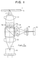
- Figure 1 is a view showing the plan structure of an optical pickup apparatus of the first embodiment of the optical pickup apparatus for the magneto-optic storage device of the present invention used when information recorded on, for example, a magneto-optic disk is reproduced.
- This optical pickup apparatus is constituted by a laser beam source 11; a collimate lens 12 which collimates the emitted light from this laser beam source 11 to a parallel beam; an objective lens which converges the parallel beam from this collimate lens 12 and irradiates the same to the recording surface 1a of the magneto-optic disk 1; a polarization beam splitter (PBS) 14 which is arranged between the laser beam source 11 and the objective lens 13 and splits the predetermined polarization beam component in the reflection light reflected at the recording surface 1a of the magneto-optic disk 1; a 1/2-wavelength plate 15 which is arranged between the polarization beam splitter 14 and the magneto-optic disk 1, in which the C axes in the regions 15a and 15b obtained by division into at least two, i.e., left and right (or upper and lower) on the plane orthogonal to the light axis O-O', that is the C1 axis and C2 axis, are set to have different angles; a
- the laser beam source 11 is constituted by, for example, a semiconductor laser.
- the collimate lens 12 collimates the emitted light from the laser beam source 11 to a parallel beam and makes the same incident upon the polarization beam splitter 14.
- the P wave having the plane of polarization (vibration direction) parallel to, for example, the P axis is output from the laser beam source 11.
- the reflectance is 0 percent with respect to the P wave and 100 percent with respect to the S wave.
- the transmittance of the polarization beam splitter 14 is 100 percent with respect to the P wave and 0 percent with respect to the S wave. Accordingly, the polarization beam splitter 14 transmits the emitted light, which is the P wave, from the laser beam source 11 100 percent therethrough, and the P wave transmitted through the polarization beam splitter 14 is incident upon the 1/2-wavelength plate 15.
- the 1/2-wavelength plate 15 has at least two division regions 15a and 15b on the plane vertical (orthogonal) to the light axis.
- the C axes in these regions that is, C1 axis and C2 axis, have the different angles.
- the boundary of the regions 15a and 15b obtained by division into two on the plane orthogonal to the light axis O-O' runs through the light axis O-O', and the C axis which is in parallel to the S axis and is the phase advanced axis of the 1/2-wavelength plate 15 has a first axis having an angle of 45 degrees with respect to the P axis in the first division region 15a (hereinafter this axis is referred to as the C1 axis) and a second axis having an angle of -22.5 degrees with respect to the P axis in the second division region 15b (hereinafter this axis is referred to as the C2 axis).
- the optical component (hereinafter referred to as the laser beam I1) passing through the first division region 15a in the P wave from the polarization beam splitter 14 passes through the first division region 15a as shown in for example Fig. 3, whereby it is converted so that the vibration plane thereof becomes linearly symmetrical relative to the C1 axis and becomes the laser beam I11 which is the S wave.
- the component (hereinafter referred to as the laser beam I2) passing through the second division region 15b in the P wave from the polarization beam splitter 14 passes through the second division region 15b as shown in for example Fig. 4, whereby it is converted so that the vibration direction thereof becomes linearly symmetrical relative to the C2 axis and becomes the laser beam I21, the vibration plane of which has an angle of -45 degrees with respect to the P axis.
- the laser beam I1 on the left side on the sheet surface and the laser beam I2 on the right side with respect to the light axis O-O' in Fig. 1 in the emitted light from the laser beam source 11 are respectively converted to the laser beam I11 of the S wave and the laser beam I21 having a vibration direction of -45 degrees with respect to the P axis by the 1/2-wavelength plate 15, and then are converged by the objective lens 13 and irradiated to the recording surface 1a of the magneto-optic disk 1.
- the recording surface 1a of the magneto-optic disk 1 is magnetized in a predetermined direction on the basis of the storage information.
- the laser beams I11 and I21 are reflected at the recording surface 1a of the magneto-optic disk 1, whereby the vibration direction thereof is rotated exactly by - ⁇ degrees as shown in Fig. 3 and Fig. 4 by the interaction between the light and magnetization, for example, the "electrooptic Kerr effect", and they are converted to the laser beams I12 and I21 with planes of vibration which respectively come to have an angle of - ⁇ degrees with respect to the laser beams I11 and I21 and, at the same time, their optical paths are inverted between the outgoing path and returning path with the light axis O-O' as a boundary.
- the laser beam I12 which is the reflection beam of the laser beam I11, passes through the right side on the sheet surface with respect to the light axis O-O' in Fig. 1
- the laser beam I22 which is the reflection beam of the laser beam I21, passes through the left side on the sheet surface with respect to the light axis O-O'.
- the laser beams I12 and I22 reflected at the storage surface 1a of the magneto-optic disk 1 are collimated to parallel beams by the objective lens 13, and then are made incident upon the 1/2-wavelength plate 15 again.
- the 1/2-wavelength plate 15 Since the 1/2-wavelength plate 15 has the C1 axis and C2 axis having different angles in the two division regions 15a and 15b as mentioned above, the laser beam I12 reflected at the recording surface 1a of the magneto-optic disk 1, passing the right side of the light axis O-O', passes through the second division region 15b, whereby, as shown in Fig. 3, it is converted so that its plane of vibration becomes linearly symmetrical relative to the C2 axis, and becomes the laser beam I13 having a plane of vibration advanced exactly by ⁇ degrees with respect to the component (indicated by a broken line) having a vibration direction coincident with the C1 axis obtained in a case where it is assumed that there is no electrooptic Kerr effect.
- the reflectances with respect to the P wave and the S wave become 0 percent and 100 percent, respectively, and therefore in the polarization beam splitter 14, only the S wave components of the laser beams I13 and I23 are reflected and are made to be incident upon the detector 16 via the condenser lens 17 and the cylindrical lens 18.
- the component obtained by projecting the laser beam I13 to the S axis (hereinafter referred to as light component I 1S ) and the component obtained by projecting the laser beam I23 to the S axis (hereinafter referred to as light component I 2S ) are made incident upon the detector 16.
- the detector 16 is divided into a plurality of parts in the light receiving region thereof, for example, as shown in Fig. 6, is divided into four regions 16a, 16b, 16c, and 16d.
- the divisional arrangement is an arrangement in which the level of the light component I 1S is detected by the regions 16b and 16c, and the level of the light component I 2S is detected by the regions 16a and 16d.
- the level signals detected at the regions 16a, 16b, 16c, and 16d of the detector 16 are the level signals A, B, C, and D, respectively, by finding the difference of the level signals (B+C) detected by the two of the regions 16b and 16c from the level signals (A+D) detected by the two of the regions 16a and 16d, that is, by the "Push ⁇ Pull method", as shown in Fig.
- the optical pickup apparatus for the magneto-optic storage device of the first embodiment of the present invention mentioned above and the conventional optical pickup apparatus for a magneto-optic storage device mentioned above will be compared.
- the light detector needed in the conventional optical pickup apparatus for the magneto-optic storage device, the 1/2-wavelength plate and polarization beam splitter used in place of the light detector, and the Wollaston prism replacing the light detector become unnecessary in the optical pickup apparatus of the present invention. That is, in the optical pickup apparatus of the present invention, the number of parts can be reduced, the size of the apparatus can be made smaller, and a lower price can be realized.
- the reflectance of the polarization beam splitter with respect to the P wave component must be set so that the amount of light incident upon the detector and the noise are well balanced, but in the present invention, the reflectance of the polarization beam splitter 14 with respect to the P wave component can be set to 0 percent in actuality, that is, the so-called coupling efficiency in the outgoing path can be made almost 100 percent, and thus a high coupling efficiency can be obtained. As a result, it becomes possible to use even a laser diode having a small output power as that used in a compact disk (CD) device etc. in the optical pickup apparatus for the magneto-optic storage device of the present invention.
- CD compact disk
- the amount of light of the P wave component and the S wave component of the laser beam passed through the 1/2-wavelength plate 15 two times is made almost 50 percent based on the emitted light, whereby it is possible to make the same resistant to the effect of the birefringence.
- the 1/2-wavelength plate 15 is formed so that the inclinations of the C1 axis and C2 are made different from each other between the region 15a and region 15b as mentioned above, whereby it can be considered that an influence is exerted upon the MO signal by the boundary between the region 15a and the region 15b, but as shown in Fig. 6, by not detecting the part corresponding to the boundary at the detector 16, it is possible to reduce the influence to zero.
- the MO signal and the focus error signal FE can be detected by one optical system.
- the optical pickup apparatus for the magneto-optic storage device of the present invention can be made to have almost the same simple structure as that of the optical pickup apparatus for the optical disk of the type used only for reproduction, of the write once type, etc. That is, the structure can be made simple compared with the conventional optical pickup apparatus for a magneto-optic storage device.
- the structures of the above-mentioned 1/2-wavelength plate 15, detector 16, etc. are not restricted to the structures shown in Fig. 1.
- the detector 19 or a 1/2-wavelength plate 15 having a large light receiving surface area on the corresponding plane of the polarization beam splitter 14 in close contact to detect the MO signal without the use of the condenser lens 17.
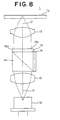
- Figure 8 is a plan structural view of the optical pickup apparatus for a magneto-optic storage device of the first modified aspect of the structure of the optical ⁇ pickup apparatus of the first embodiment shown in Fig. 1.
- the optical pickup apparatus shown in Fig. 8 has a laser beam source 11, a collimate lens 12, a polarization beam splitter 14, a 1/2-wavelength plate 15, a detector 19 having a large light receiving surface area, and an objective lens 13.
- the distance between the polarization beam splitter 14 and the objective lens 13 is shortened. Further, in the optical pickup apparatus shown in Fig. 8, the condenser lens 17 and the cylindrical lens 18 are unnecessary. As a result, the optical pickup apparatus shown in Fig. 8 becomes further smaller in size than the optical pickup apparatus shown in Fig. 1.
- the laser beam source 11A of Fig. 8 uses for example a laser unit equipped with a hologram provided with for example a focus error detection function.
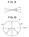
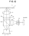
- Figure 11 is a plan structural view of the optical pickup apparatus of the second modified aspect of the first embodiment of the present invention in which the polarization beam splitter 14A formed in this way is arranged in the dispersion light (or converged light) of the laser beam source 11.
- the optical pickup apparatus shown in Fig. 11 has a laser beam source 11, a 1/2-wavelength plate 15A formed as shown in Fig. 10, a polarization beam splitter 14A reducing the phase difference to almost 0, an objective lens 13, a condenser lens 17, a cylindrical lens 18, and a detector 16.
- the MO signal can be detected by using almost 100 percent of the S wave component produced by the electrooptic Kerr effect, and therefore it is possible to considerably improve the S/N in comparison with the conventional optical pickup apparatus.
- angles ⁇ 1 and ⁇ 2 of the planes of vibration of the laser beams I3 and I4 with respect to the P axis illustrated in Fig. 9 so as to be not equal to each other, and set for example ⁇ 2 to almost 0 degree, and as illustrated in Fig. 12, use one photoelectric conversion element (detector) having an undivided light receiving plane for the MO signal, for example, an avalanche photodiode (APD) 16A in place of the detector 16 shown in Fig. 11.
- a photoelectric conversion element detector
- APD avalanche photodiode
- the laser beam source 11 it is also possible to rotate the laser beam source 11 a little around the light axis O-O', that is, change the state so that a small amount of the S wave component exists in the emitted light from the laser beam source 11, take out this S wave component in an opposite direction (left side in the drawing) to the detector 16 shown in Fig. 11 or the APD 16A shown in Fig. 12 by the polarization beam splitter 14, and perform front automatic power control (FAPC) of the laser beam source 11 based on the level of this component.
- FAPC front automatic power control
- the emitted light from the laser beam source 11, passing through the polarization beam splitter 14A consists of only the P component, and therefore there is no influence on the detection of the MO signal.
- This optical pickup apparatus is constituted by, as shown in Fig. 13, a laser coupler 20 formed by providing a laser beam source, a polarization beam splitter, a detector, etc. on the same silicon substrate; two silicon mirrors 31 and 32 for moving (polarizing) the light axis O-O' of the emitted light from this laser coupler 20; an objective lens 33 converging the emitted light reflected at the silicon mirror 32 and irradiating the same onto the recording surface 1a of the magneto-optic disk 1; and a 1/2-wavelength plate 34 which is arranged between the laser coupler 20 and the magneto-optic disk 1 and has at least two divided regions 34a and 34b obtained by division into at least two on the plane orthogonal to the light axis O-O', the C1 axis and C2 in these regions having different angles.
- the laser coupler 20 is constituted by, for example, as shown in Fig. 14, a laser beam source 22 provided on the silicon substrate 21; a microprism 23 which has a plane of polarization arranged along the light axis O-O' between this laser beam source 22 and the objective lens 33, splits the predetermined polarized beam component in the reflection light reflected at the recording surface 1a of the magneto-optic disk 1 and, at the same time, for producing the focus error signal FE; and detectors 24 and 25 which are formed on the silicon substrate 21 and respectively detect the light amounts at positions an equal distance from the focal point, respectively.
- the light receiving regions of the detectors 24 and 25 are divided to, for example, as shown in Fig. 15, three regions 24a, 24b, and 24c and three regions 25a, 25b, and 25c, respectively.
- the optical pickup apparatus shown in Fig. 13 sets the C1 axis and C2 axis in regions of the 1/2-wavelength plate 34 obtained by division into at least two on the plane vertical (orthogonal) to the light axis O-O', for example, in the two division regions 34a and 34b, to have different angles and, at the same time, set the reflectances of the plane 23a of the microprism 23 with respect to the P wave and S wave to 0 percent and 100 percent, respectively, and makes the reflection light in the emitted light from the laser beam source 22, passed through the first region 34a of the 1/2-wavelength plate 34 and reflected at the recording surface 1a of the magneto-optic disk 1, pass through the second region 34b of the 1/2-wavelength plate 34, and makes the reflection light in the emitted light from the laser beam source 22, passed through the second region 34b of the 1/2-wavelength plate 34 and reflected at the recording surface
- the optical pickup apparatus of the third modified aspect of the first embodiment shown in Fig. 13 has a structure in which the collimate lens 12 in the optical pickup apparatus of the embodiment shown in Fig. 1 and Fig. 8 is deleted, and the optical pickup apparatus is further reduced in size.
- an optical pickup apparatus shown in Fig. 16 can be constituted by combining the optical pickup apparatus shown in Fig. 8 and the optical pickup apparatus shown in Fig. 11 or Fig. 12, or Fig. 13.
- the collimate lens 12 and objective lens 13 in the optical pickup apparatus illustrated in Fig. 1 are deleted, and further the condenser lens 17 and the cylindrical lens 18 are deleted. Accordingly, in comparison with the optical pickup apparatus shown in Fig. 1, the length in the light axis O-O' direction, and the length in the direction orthogonal to the light axis O-O' are shortened very much, and the optical pickup apparatus can be further reduced in size.
- the optical pickup apparatus of the first embodiment of the present invention is not restricted to the structure illustrated in Fig. 16 and can have any structure obtained by appropriately selecting and combining the structures of Fig. 1, Fig. 8, Fig. 11, Fig. 12, and Fig. 13.
- the light axis of the S wave component split at the polarization beam splitter 14 or the plane 23a of the microprism 23 is made a diametrical (or radial) direction of the magneto-optic disk 1, but it is also possible to arrange the optical pickup apparatus so that the light axis of this S wave component becomes the tangential direction of the tracks of the magneto-optic disk 1 and detects the MO signal by the "tangential push-pull method".
- the present invention can be applied to various types of control systems of a beam spot in an optical pickup apparatus, for example, an optical pickup apparatus using the "three beam method".
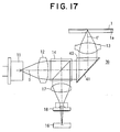
- the optical pickup apparatus of the second embodiment of the optical pickup apparatus for the magneto-optic storage device of the present invention will be explained next referring to Fig. 17 to Fig. 21.
- Figure 17 is a plan structural view of the optical pickup apparatus of the second embodiment of the optical pickup apparatus for a magneto-optic storage device of the present invention.
- This optical pickup apparatus comprises the laser beam source 11; a collimate lens 12; a polarization beam splitter 14; a combination phase retardation prism (CPR) 39; an objective lens 13; a condenser lens 17; a cylindrical lens 18; and a detector 16.
- CPR combination phase retardation prism
- the optical pickup apparatus shown in Fig. 17 uses the CPR 39 in place of the 1/2-wavelength plate 15 of the optical pickup apparatus shown in Fig. 1.
- the other constituent members are the same as those shown in Fig. 1. Note, the path of the light axis O-O' is different due to the use of the CPR 39.
- the CPR 39 shown in Fig. 18a is formed by coating a phase difference generating thin film 41 on the reflection plane 40a of the 45 degree prism 40, and the phase difference generating thin film 41 comprises a first phase difference generating thin film 41a and a second phase difference generating thin film 41b.
- the first phase difference generating thin film 41a and second phase difference generating thin film 41b have almost the same surface area and are symmetrically coated on the two sides of the reflection plane 40a in a vertical direction with the center of the reflection plane 40a as the light axis O-O'.
- phase difference generating thin films 41a and 41b all reflect the incident light.
- the first phase difference generating thin film 41a reflects the same without the change of the phase of the incident light
- the second phase difference generating thin film 41b reflects the incident light by retarding the same by 180 degrees.
- Such a phase retardation can be achieved by adjusting the film thickness of these phase difference generating thin films 41a and 41b.
- the CPR 39 exhibits a similar function to that of the 1/2-wavelength plate 15 shown in Fig. 1.
- the CPR 39A shown in Fig. 18b is formed by coating the first phase difference generating thin film 41aA and the second phase difference generating thin film 41bA as total reflection films obliquely on the reflection plane 40a half and half obliquely. These films are formed so that a phase difference of 180 degrees is produced between the first phase difference generating thin film 41aA and the second phase difference generating thin film 41bA.
- the CPR 39B shown in Fig. 18c is formed by coating the first phase difference generating thin film 41aB and the second phase difference generating thin film 41bB as total reflection films on the surface of the reflection plane 40a half and half vertically. These films are formed so that a phase difference of 180 degrees is produced between the first phase difference generating thin film 41aB and the second phase difference generating thin film 41bB.
- any of the CPR 39, 39A, and 39B illustrated in Fig. 18a to Fig. 18c can be used, but a case using the CPR 39 illustrated in Fig. 18a will be exemplified below.
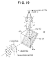
- Figure 19 is a view illustrating the ray tracing on the periphery of the CPR 39 in Fig. 17.
- the ray tracing will be mentioned.
- the light L1 from the polarization beam splitter 14 is reflected at the second phase difference generating thin film 41b of the CPR 39, passes through the objective lens 13, and is irradiated onto the recording surface 1a (MO film reflection plane) of the magneto-optic disk 1 as the converged light L2, and that reflected light L3 passes through the objective lens 13 and is incident upon the first phase difference generating thin film 41a of the CPR 39, reflected thereat, and emitted to the polarization beam splitter 14.
- Equation 1 Equation 1, equation 2, equation 4, and equation 5 stand also in this second embodiment.
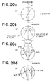
- Figure 20a to Fig. 20d are graphs showing the characteristics of the above-described lights L1 to L4.
- the plane of polarization of the light L1 is inclined exactly at the angle ⁇ .
- the C axes of the 1/2-wavelength plate 15, that is, the C1 axis and C2 axis, are in the P direction.
- the reflected light irradiated onto the recording surface 1a of the magneto-optic disk 1 via the objective lens 13 and that reflected reflection beam is inverted in the light path.
- the phase is deviated exactly by the angle + ⁇ k by the electrooptic Kerr effect.
- the light L3 in the returning path is reflected at the first phase difference generating thin film 41a, whereby the phase is deviated by 90 degrees.
- the surface areas of the semi-spheres are respectively converted to: - ( ⁇ ⁇ ⁇ k) and therefore when it is detected at the polarization beam splitter 14 and the differentiation in the detector 16 is obtained, also in the second embodiment, a result similar to that in the above-mentioned first embodiment is obtained, and the MO signal can be detected.
- An optical pickup apparatus of the first embodiment using the 1/2-wavelength plate 15 shown in Fig. 1 is compared with the optical pickup apparatus of the second embodiment using the CPR 39.
- the 1/2-wavelength plate 15 is produced, as shown in Fig. 2, by bonding a first 1/2-wavelength plate 15a and a second 1/2-wavelength plate 15b, obtained by division into two, about the light axis O-O' as a center (as the boundary), but in actuality, it is difficult to precisely produce the same, and it is not always suitable for mass production.
- the CPR 39 is formed by only coating the phase difference generating thin film 41 to the 45 degree mirror 40, and therefore can be easily produced, and thus is excellent in mass producibility.
- the division of the beam spot by the inclination of the light axis which probably occurs where the 1/2-wavelength plate 15 is used, does not occur.
- the vector-interference degree can be arbitrarily set by the angle ⁇ shown in Fig. 20a to Fig. 20d where the CPR 39 is used.
- the CPR 39 can be detected at an angle two times the angle ⁇ , and therefore the wave detection sensitivity becomes higher.
- the optical pickup apparatus of the second embodiment using the CPR 39 the light axis O-O' is deflected by the CPR 39, and therefore it is possible to reduce the distance between the laser beam source 11 and the objective lens 13. That is, there is an advantage that the optical pickup apparatus of the second embodiment can reduce the size of the optical system.
- the CPR 39 can be produced at a low cost.
- the reflected returning beam is the polarization beam in the same direction, but only the MO signal can be obtained in an inverse phase.
- the CPR 39, 39A, and 39B shown in Fig. 18a to 18c or the CPR 39 having the structure according to the same concept as that for them not only can be applied to the optical pickup apparatus, but also can be used for a wider purpose as a phase difference generation device for generating a predetermined phase difference between one light incident upon a first phase difference generating thin film 41a and the other light incident upon a second phase difference generating thin film 41b.
- This phase difference generation device can arbitrarily change the phase difference according to the film thickness of the phase difference generating thin film 41 coated on the reflection plane 40a of the 45 degree prism 40.
- the coating method of the phase difference generating thin film 41 various coating methods in accordance with the material of the phase difference generating thin film 41, for example, a coating method such as sputtering, can be applied.
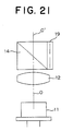
- Figure 21 is a structural view of an integral construction of the polarization beam splitter 14 corresponding to Fig. 7 and the detector 19 having a large light receiving surface area of the first modified aspect of the second optical pickup apparatus.
- the 1/2-wavelength plate 15 is not used in the optical pickup apparatus of the second embodiment, and therefore the 1/2-wavelength plate 15 shown in Fig. 7 is not face-adhered to the polarization beam splitter 14 in Fig. 21.
- the polarization beam splitter 14 and the detector 19 having a large light receiving surface area shown in Fig. 21 can be applied to the optical pickup apparatus shown in Fig. 17.
- the condenser lens 17 and cylindrical lens 18 shown in Fig. 17 become unnecessary.
- a structure corresponding to Fig. 11 and Fig. 12 that, is a structure formed by deleting the collimate lens 12 between the laser beam source 11 and the polarization beam splitter 14A, can be adopted.
- the advantage of this second modified aspect is similar to the advantage in the optical pickup apparatus shown in Fig. 11 and Fig. 12. The illustration of this structure will be omitted.
- a structure corresponding to Fig. 13 can be adopted.
- the advantage of this third modified aspect is similar to the advantage in the optical pickup apparatus shown in Fig. 13. An illustration will be omitted for also this structure.
- Figure 22 is a plan structural view of the optical pickup apparatus of the third embodiment.
- This optical pickup apparatus comprises a laser beam source 11; a collimate lens 12; a polarization beam splitter 14; an optical rotating plate 52; an objective lens 13; a condenser lens 17; a cylindrical lens 18; and a detector 16.
- the optical pickup apparatus shown in Fig. 22 differs from the optical pickup apparatus shown in Fig. 1 only in a point that the optical rotating plate 52 is used in place of the 1/2-wavelength plate 15 shown in Fig. 1.
- the fundamental structure and the other constituent members are the same as those of the optical pickup apparatus shown in Fig. 1.
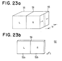
- the optical rotating plate 52 is constituted by the left optical rotating plate 52a and the right optical rotating plate 52b.
- the left optical rotating plate 52a rotates only the polarized beam exactly at the predetermined angle in a counterclockwise direction seen from the observation side, that is, from the objective lens 13 side in this example, without a change of the phase difference (true also for the following).
- the right optical rotating plate 52b rotates only the polarized beam exactly at the predetermined angle in the clockwise direction seen from the observation side without a change of the phase difference.
- the left optical rotating plate 52a and the right optical rotating plate 52b do not give an optical phase difference (retardation) to the transmission light, and therefore rotate the same as linear polarization as is. Even if the wavelength is changed, only the optical rotary power is changed. Accordingly, a difference of the optical rotation angles of exactly the sum of the optical rotation angles of the two is produced between the light incident upon the left optical rotating plate 52a and the light incident upon the right optical rotating plate 52b.
- an optical member 55 having a right optical rotation angle having a thick thickness t0 and an optical member 54 having a left optical rotation angle and having almost the same thickness are surface-adhered at the plane of the center line corresponding to the light axis O-O'.
- the thicknesses of these optical members 54 and 55 are great, and accordingly this surface-adhesion work can be easily carried out.
- optical members 54 and 55 for example, crystals obtained by cutting quartz orthogonally to the optical axis is used.
- the right crystal is used as the optical member 55 having the right optical rotation angle and the left crystal is used as the optical member 54 having the left optical rotation angle.
- the optical rotary power giving the optical rotation angle is physically determined. That is, the wavelength dependency of the optical rotation angle becomes the value shown in the following Table 1.
- the optical rotation angle is determined by the thickness t of the optical material.
- a optical rotating plate 52 having a desired thickness t is produced by polishing from the two surfaces the optical materials 54 and 55 having a thickness t0 in a state where they are face-adhered.
- the desired thickness t is, for example, about 3.7 mm in the case of an optical rotation angle of 45 degrees.
- the polishing is performed until the predetermined thickness t is obtained in accordance with the desired optical rotation angle.
- This polishing work can also be easily carried out. Accordingly, the optical rotating plate 52 formed by the face-adhesion of the left optical rotating plate 52a and the right optical rotating plate 52b can be easily produced and can be produced at a low cost and in a short time.
- the optical rotation angle can be arbitrarily set.
- the optical rotation angle is in substantially proportional to the thickness thereof.
- the linear polarized beam can be made incident toward any direction in the plane, and it is not necessary to define the polarization angle ⁇ of the incident light as shown in Fig. 20a, and therefore the degree of freedom of design can be enhanced.
- An optical rotating plate 52 formed by a combination of two plates, a left optical rotating plate 52a and a right optical rotating plate 52b, formed in this way is called a combination optical rotating plate (CRP).
- CRP combination optical rotating plate
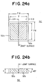
- Figure 24a is a front view of a CRP used in the third embodiment of the present invention
- Fig. 24b is a top plan view thereof.
- the numerals in the drawings show the actual dimensions using mm as the units. The machining precision was ⁇ 0.1 mm.
- a clear aperture indicated by a hatching indicating an effective light transmission surface area is 7 mm x 7 mm.
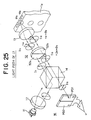
- Figure 25 and Fig. 26 are perspective views of the optical pickup apparatus illustrated in Fig. 22. Note, the orientation of the incident light from the laser beam source 11 and collimate lens 12 to the polarization beam splitter 14 and the orientation of the emitted light from the polarization beam splitter 14 to the detector 16 are different from those in Fig. 22.
- Figure 25 shows the conversion of the plane of polarization of I1
- Fig. 26 shows the conversion of the plane of polarization of I2.
- the orientations of the arrows in the circles show the orientations of the polarization of the linear polarized beam.
- the laser beam I1 which is the S polarized beam from the collimate lens 12, is completely reflected at the polarization beam splitter 14, and when it passes through the left optical rotating plate 52a, becomes the laser beam I11 obtained by the rotation of the plane of polarization exactly at + ⁇ .
- this laser beam I11 passes through the objective lens 13, is reflected at the recording surface 1a of the magneto-optic disk 1, and passes again through the objective lens 13, the returning light becomes the laser beam I12 passing through the light path on the opposite side while sandwiching the center axis of the objective lens 13 (light axis O-O') therebetween.
- the plane of polarization at this time is + ⁇ as is.
- this laser beam I12 passes through the right optical rotating plate 52b, it is then given optical rotation in the clockwise direction.
- the advance direction (orientation) of the laser beam is reverse between the left optical rotating plate 52a and the right optical rotating plate 52b, and therefore it means that the rotation in the clockwise direction further becomes + ⁇ , and the laser beam I13 transmitted through the right optical rotating plate 52b is rotated exactly by +2 ⁇ with respect to the laser beam I1 incident upon the left optical rotating plate 52a. That is, there is an optical rotation angle of +2 ⁇ in total between the incident light I1 and the emitted light I13 with respect to the optical rotating plate 52.
- the laser beam I13 receives the wave detection of polarization in the polarization beam splitter 14, only the P wave component is transmitted, and the Laser beam I 1S is incident upon the detector 16.
- the amplitude of the laser beam I 1S incident upon the detector 16 becomes the value indicated by the following equation 6.
- the conversion of the plane of polarization of the light path I2 shown in Fig. 26 becomes similar to that described above in principle.
- the laser beam I2 which is the S polarized beam from the collimate lens 12, is completely reflected at the polarization beam splitter 14, and when it passes through the right optical rotating plate 52b on the opposite side to the laser beam I1, it becomes the laser beam I21 in which the plane of polarization is inversely rotated exactly by - ⁇ .
- this laser beam I21 passes through the objective lens 13, is reflected at the recording surface 1a of the magneto-optic disk 1, and passes again through the objective lens 13, the returning light becomes the laser beam I22 passing through the light path on the opposite side while sandwiching the center axis of the objective lens 13 (light axis O-O') therebetween.
- the plane of polarization at this time is - ⁇ as is.
- this laser beam I22 passes through the left optical rotating plate 52a, it is then given rotation in the counterclockwise direction.
- the advance direction (orientation) of the laser beam is reverse between the left optical rotating plate 52a and the right optical rotating plate 52b, and therefore it means that the optical rotation in the counterclockwise direction further becomes - ⁇ , and the laser beam I23 transmitted through the left optical rotating plate 52a is rotated exactly by 2 ⁇ with respect to the laser beam I2 incident upon the right optical rotating plate 52b. That is, there is an optical rotation angle of -2 ⁇ in total between the incident light I1 and the emitted light I23 with respect to the optical rotating plate 52.
- the laser beam I23 receives the wave detection of polarization in the polarization beam splitter 14 , and the laser beam I23 is incident upon the detector 16.
- the amplitude of the laser beam I13 incident upon the detector 16 becomes the value indicated by the following equation 7.
- I23 x sin (-2 ⁇ ) (7) In this way, in the optical pickup apparatus shown in Fig. 25 and Fig. 26, a similar effect as if the Faraday element were used can be obtained. Note, in this optical pickup apparatus, the loss of the amount of light met where the Faraday element is used is theoretically zero, and a better effect is exhibited than that of the case using a Faraday element.
- MO signal is found from the differential detection of the signals obtained from the PD1 and PD2 of the detector 16.
- MO signal PD1 - PD2 (8)
- Sum (RF) signal PD1 + PD2 (9)
- Figure 27 is a view illustrating the wave detection of the MO signal by the double cross-section differential detection method.
- the double cross-section differential detection method was named in this way because while there is apparently a single laser beam, use is made of a laser beam with a cross-section controlled in polarization independently at its half-moon shaped areas so as to detect the MO signal from the differentiation of area of the light amount.
- the MO signal is the transmission light of the polarization beam splitter 14, and therefore both of the laser beams I 1S and I 2S have only the S polarized beam component. That is, the ⁇ 1 component is detected as the difference of the light intensity in the reflection stage, and when the differentiation between two signals is taken, the same phase component is removed.
- the present invention in principle, it is possible to perform the removal of the same phase up to the extinction rate of the polarization beam splitter 14, and therefore an intended MO signal having a high same phase removing ratio and high quality can be obtained.
- the MO signal can be detected out by a similar processing as with a push-pull. As a result, it is possible to constitute the detection system of the MO signal by a planar structure, and therefore the optical pickup apparatus can be made small in size.
- the MO signal can be detected by almost the same structure as that of the optical system of CD.
- the polarization beam splitter 14 is used, and therefore the retardation basically does not occur.
- the light amount is detected only in the return light path from the recording surface 1a and the light amount in the outgoing path is substantially completely transmitted, therefore the coupling efficiency is improved.
- the optical rotation angle of the combination optical rotating plate 52 without any effect upon the coupling efficiency in the outgoing path, and therefore the amount of the incident light upon the detector 16 can be controlled.
- the optical rotation angles of the left optical rotating plate 52a and the right optical rotating plate 52b are changed to 0 to 45°, respectively, the returning light to the detector 16 can be arbitrarily set to 0 to 100 percent. That is, when the optical rotation angle of the combination optical rotating plate 52 is adjusted, it is possible to arbitrarily set the returning light, and therefore freedom of design of the amplifier connected to the output side of the detector 16 can be given, and thus the SN is improved.
- the sums of the optical rotation angles in the outgoing path and return path become equal to (right optical rotation angle + left optical rotation angle) in both of the laser beam I 1S and the laser beam I 2S , and therefore it is not necessary to strictly set the specifications of the elements of the combination optical rotating plate 52.
- the polarization beam splitter 14 is cheap in comparison with the beam splitter for the MO, and also the combination optical rotating plate 52 is more inexpensive than a Wollaston prism.
- the optical pickup apparatus of the present invention is constituted as illustrated in Fig. 28.
- Figure 28 corresponds to Fig. 13 illustrating the structure of the optical pickup apparatus using the 1/2-wavelength plate 15 as the first embodiment.
- the 1/2-wavelength plate 15 is not provided in the optical pickup apparatus shown in Fig. 28, but an optical assembly 60 formed by integrally constituting the combination optical rotating plate 52, the polarization beam splitter 14, and the detector 16 as shown in Fig. 29 is provided in the attachment part of the silicon mirror 31.
- a laser coupler 20 similar to the one illustrated in Fig. 14 is provided above the plane 14a of the polarization beam splitter 14.
- the silicon mirror 32 is arranged in the optical assembly 60, and the objective lens 13 is arranged at the top thereof.
- the above-mentioned combination optical rotating plate 52 is not only used in the optical pickup apparatus for the magneto-optic storage device of the present invention, but can be applied to other various purposes changing the phase of the light and consequently generating a phase difference between a plurality of lights similar to the CPR 39 mentioned referring to the second embodiment.
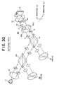
- FIG. 30 A fourth embodiment of the optical pickup apparatus for the magneto-optic storage device of the present invention will be explained next referring to Fig. 30 to Fig. 42.
- MTF space frequency axis
- Figure 30 and Fig. 31 are diagrammatical views of an optical system of an optical pickup apparatus of the fourth embodiment.
- Figure 30 shows the outgoing path and Fig. 31 shows the return path.
- This optical pickup apparatus uses the combination optical rotating plate 62 in place of the combination optical rotating plate 52 of the optical pickup apparatus shown in Fig. 22 of the third embodiment or in Fig. 25 and Fig. 26 and provides a beam splitter 64 between the collimate lens 12 and the polarization beam splitter 14 and also a second detector 66 on the emission side of this beam splitter 64.
- the laser beam source 11, collimate lens 12, polarization beam splitter 14, objective lens 13, and magneto-optic disk 1 (recording surface 1a) are similar to those of the optical pickup apparatus shown in Fig. 22.
- the beam in the combination optical rotating plate 62 differs between the half-moon shaped division regions, and the beam spot obtained by converging these beams by the lens differs from the usual beam spot.
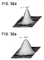
- Figure 32a to Fig. 32e respectively show the results of finding the beam spot by setting the optical rotation angle ⁇ of the combination optical rotating plate 62 to 5°, 10°, 22.5°, 30°, and 45°, by simulation.
- the optical rotation angle ⁇ becomes larger, the distribution of the outer beam spot are expanded in the division direction.
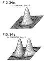
- Fig. 33 the results of simulation of how the beam spot becomes for each component in each direction where the direction along the divisional line 620 of the combination optical rotating plate 62 is an x-direction and the direction orthogonal to the divisional line 620 is the y-direction are shown in Fig. 34a and Fig. 34b. From this, there can be found the beam spot of the y-component having the same polarization direction as the so-called beam spot in the x-direction, i.e., of the same phase component but having the inverted phase to this. In the beam spot of the component in the y-direction, the light amount always becomes zero since the phase is inverted by 180° at the center of the beam.
- the beam spot becomes the beam light shape per se of the y-component E y .
- the energy distribution of this beam spot is important.
- the MTF and other parameters can be determined by this PSF (point spread function).
- the E x component and the E y component have different PSFs.
- the MO signal can be found by the double cross-section differential detection method.
- an experiment was carried out for the case of an arrangement using a push-pull for the case where the division line 620 of the combination optical rotating plate 62 was arranged in parallel to the pregroove of the recording surface 1a as shown in Fig. 35, and it was divided into left and right portions, i.e., a left optical rotating plate 62a and a right optical rotating plate 62b. It was confirmed that there was an effect of outputting the MO signal and removing the push-pull signal.
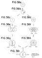
- Figure 36a to Fig. 36g and Fig. 36h show the respective beam states at the positions of I12 and I22 in the outgoing path shown in Fig. 31.
- Fig. 36a Referring to Fig. 30 and Fig. 31, in the plane of polarization of the laser beam reflected by the polarization beam splitter 14, all beam planes are in the S direction. The amplitude at this time is standardized to "1". Also the reflectance of the recording surface 1a of the magneto-optical disk 1 is set to "1".
- Fig. 36b The laser beams passed through the combination optical rotating plate 62 and reflected at the recording surface 1a are defined as I22 and I12.
- Fig. 36c and Fig. 36d The beam is considered while dividing the same to the E x component and the E y component. Then, a case where these beams are subjected to the S axis diffraction at the recording surface 1a is assumed.
- the pregroove is considered in the space frequency region of more than 1/NA (number of openings) at which the push-pull becomes maximum.
- Fig. 36e and Fig. 36f They indicate the superposing of the primary diffraction light by the pregroove (+/-) and the 0 order light.
- the intensities of (+/-) primary diffraction lights are l and r , and the intensity of the 0 order light is defined as c. Since the (+/-) primary diffraction lights are diffracted to l times and r times, respectively, in the form including also the plane of polarization, they exhibit inverse phases in the superposed part on the 0 order light in Fig. 36f.
- Fig. 36g and Fig. 36h The characteristics illustrated in Fig. 36e and Fig. 36f are indicated by the amplitude.
- Figure 36i and Fig. 36j show the state of the beams I13 and I23 in the outgoing path shown in Fig. 30 at different positions.
- Fig. 36i and Fig. 36j In a step where the light reflected at the recording surface 1a is returned, when it passes through the combination optical rotating plate 62 again, the plane of polarization is rotated exactly at the optical rotation angle ⁇ together with the beam shown in Fig. 36g and Fig. 36h, and therefore there exist again the E x component and the E y component in a mixed manner.
- Figure 36k and Fig. 36l show the state of the beams I 1SA and I 2SA in the outgoing path indicated in Fig. 30 at different positions.
- Fig. 36k and Fig. 36l The characteristics illustrated in Fig. 36i and Fig. 36j are wave-detected at the polarization beam splitter 14 and only the P component is transmitted.
- Fig. 36m The P components shown in Fig. 36k and Fig. 36l are added.
- both of the beams I 1SA and I 2SA are 2c ⁇ sin ⁇ cos ⁇ , the push-pull signal becomes "0", and the phase groove diffraction light does not depend upon the magnifications l , r , and c and does not depend on the optical rotation angle ⁇ .
- the S component in Fig. 36i and Fig. 36j is reflected at the polarization beam splitter 14 and this polarization beam depends on the magnifications l , r , and c and depends on the optical rotation angle a, and therefore contains the push-pull component, and thus it is possible to apply tracking servo control by the signal from the second detector 66.
- the beams I 1SA and I 2SA have the same plane of polarization but have the phase of 180°, and therefore the MO signal can be detected from (I 1SA - I 2SA ).
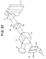
- Fig. 37 where the combination optical rotating plate 72 is divided into two, the left optical rotating plate 72a and the right optical rotating plate 72b in the tangential direction, it is possible to also take out the push-pull signal as a signal from the detector 16 by the radial push-pull method, and further to take out also the MO signal by subtraction of the signal depending on the optical rotating plate in the tangential direction.
- Figure 38a to Fig. 38i show the ray tracing corresponding to Fig. 36a to Fig. 36m in the optical system shown in Fig. 37.
- phase pit diffraction light removing (suppressing) effect A description will be made of the phase pit diffraction light removing (suppressing) effect.
- (I 1SA + I 2SA ) does not contain the information of the pregroove. Namely, a track loss signal is not derived.
- a case where the combination optical rotating plate 72 is divided in the tangential direction as illustrated in Fig. 37 means that also the phase pit is not reproduced.
- the double cross-section differential detection method is used so as to obtain the MO signal for removing such a same phase noise, and therefore the fourth embodiment exhibits an effect of the reduction of the same phase noise.
- the combination optical rotating plate 62 or the combination optical rotating plate 72 has a characteristic that the way of viewing the MO signal and pit signal differs depending upon the optical rotation angle ⁇ and the division direction in tangential the direction or the radial direction.
- Figure 39a and Fig. 39b are views of the characteristics of the differential (push-pull) signal and the characteristics of the sum (RF) signal based on simulation when the optical rotation angle ⁇ of the combination optical rotating plate 62 is equal to 0°, 5°, 22.5°, 30°, and 45° as shown in Fig. 32a to Fig. 32f.
- the abscissa shows the NA/ ⁇ .
- Figure 39b shows that the MTF of the pit train aligned in the tangential direction can be reproduced to exactly an extent of a half of the space frequency when the combination optical rotating plate 72 is divided in the tangential direction as illustrated in Fig. 37.
- the larger the optical rotation angle ⁇ of the combination optical rotating plate 72, the larger the amount of light of the beam returned to the detector 16, and therefore the absolute value varies, but as shown in Fig. 40, when it is standardized by NA/ ⁇ 0 , it is aligned to one line as indicated by a curve CV1 shown by a solid line. Note that, the curve of the broken line indicates the conventional MTF curve CV2.
- the MO signal can also be reproduced by changing the form of the MTF curve. Further, it is seen that it becomes possible to largely take out also the amplitude value of the MO signal. Particularly where ⁇ is set equal to 22.5°, wave detection is performed at 45° in PBS, and therefore the maximum amplitude can be obtained.
- Figure 41a shows the curve of the theoretical values of the MO signal and Fig. 41b shows the curve of the actually measured values. In this way, the theoretical values and the actually measured values correspond well.
- Figure 42 is a graph showing the values of Fig. 41a and Fig. 41b by the MTF curve by standardizing the same by 1.0.
- the curve CV11 shows the same phase noise, that is, RF signal;
- the combination optical rotating plate 62 or combination rotating plate 72 of the fourth embodiment of the present invention mentioned above can be applied for an optical pickup apparatus similar to Fig. 28 and Fig. 29 shown as the third embodiment.
- combination optical rotating plate 62 or the combination optical rotating plate 72 mentioned as the, fourth embodiment of the present invention can be applied to other optical apparatuses other than the optical pickup apparatus.
- the present invention is not restricted to the above-mentioned embodiments and can include other various modified aspects.
- An optical pickup apparatus for a magneto-optic storage device of the present invention can be preferably used in an optical recording and reproduction apparatus.
- the optical pickup apparatus for the magneto-optic storage device of the present invention is constituted to have a small size, and therefore also the entire magneto-optic storage device including this optical pickup apparatus for a magneto-optic storage device can be made to have a small size.
- the optical pickup apparatus for a magneto-optic storage device of the present invention can be applied to a small size magneto-optic storage device.
- the 1/2-wavelength plate, combination phase retardation prism, and combination optical rotating plate exemplified as the elements constituting the optical pickup apparatus for a magneto-optic storage device of the present invention not only can be applied to an optical pickup apparatus for a magneto-optic storage device, but also can be applied to various apparatuses changing the phase of two beams with predetermined relationships.
Landscapes
- Physics & Mathematics (AREA)
- Optics & Photonics (AREA)
- General Physics & Mathematics (AREA)
- Optical Head (AREA)
- Optical Recording Or Reproduction (AREA)
Applications Claiming Priority (7)
| Application Number | Priority Date | Filing Date | Title |
|---|---|---|---|
| JP5694592 | 1992-02-07 | ||
| JP56945/92 | 1992-02-07 | ||
| JP5694592 | 1992-02-07 | ||
| JP137769/92 | 1992-04-30 | ||
| JP13776992 | 1992-04-30 | ||
| JP13776992 | 1992-04-30 | ||
| PCT/JP1993/000158 WO1993016469A1 (fr) | 1992-02-07 | 1993-02-08 | Dispositif variateur de phase et appareil capteur optique utilisant ce dispositif pour une fonction de stockage magneto-optique |
Publications (3)
| Publication Number | Publication Date |
|---|---|
| EP0579843A1 true EP0579843A1 (de) | 1994-01-26 |
| EP0579843A4 EP0579843A4 (en) | 1996-05-08 |
| EP0579843B1 EP0579843B1 (de) | 1999-12-22 |
Family
ID=26397950
Family Applications (1)
| Application Number | Title | Priority Date | Filing Date |
|---|---|---|---|
| EP93903326A Expired - Lifetime EP0579843B1 (de) | 1992-02-07 | 1993-02-08 | Optisches abtastgerät für eine magneto-optische speicherung |
Country Status (5)
| Country | Link |
|---|---|
| US (3) | US5577018A (de) |
| EP (1) | EP0579843B1 (de) |
| JP (1) | JP3658763B2 (de) |
| DE (1) | DE69327369T2 (de) |
| WO (1) | WO1993016469A1 (de) |
Cited By (6)
| Publication number | Priority date | Publication date | Assignee | Title |
|---|---|---|---|---|
| EP0671734A1 (de) * | 1994-03-08 | 1995-09-13 | Sony Corporation | Optische Vorrichtung |
| EP0683484A1 (de) * | 1994-05-17 | 1995-11-22 | Nec Corporation | System für optischen Kopf |
| EP0762396A1 (de) * | 1995-09-08 | 1997-03-12 | Mitsubishi Denki Kabushiki Kaisha | Gerät zur Spurfolgefehlerdetektion eines optischen Kopfes |
| US5663940A (en) * | 1993-11-19 | 1997-09-02 | Sony Corporation | Optical pickup apparatus including hologram element |
| EP0735529A3 (de) * | 1995-03-31 | 1998-01-21 | Nec Corporation | Optisches Wiedergabemedium und Verfahren zur Wiedergabe von darauf gespeicherten Daten |
| US5896360A (en) * | 1994-11-10 | 1999-04-20 | Sony Corporation | Optical pickup device and optical disc driving apparatus having light polarizing hologram |
Families Citing this family (20)
| Publication number | Priority date | Publication date | Assignee | Title |
|---|---|---|---|---|
| EP0579843B1 (de) * | 1992-02-07 | 1999-12-22 | Sony Corporation | Optisches abtastgerät für eine magneto-optische speicherung |
| EP0608432B1 (de) * | 1992-07-14 | 2001-02-21 | Seiko Epson Corporation | Polarisierendes element, optisches element und optischer kopf |
| JP3451663B2 (ja) | 1993-08-18 | 2003-09-29 | ソニー株式会社 | 光ピックアップ装置 |
| KR100194455B1 (ko) * | 1995-12-30 | 1999-06-15 | 윤종용 | 팩시밀리 시스템의 예약 송신방법 |
| US6215758B1 (en) * | 1996-10-04 | 2001-04-10 | Sony Corporation | Recording medium |
| JP3110336B2 (ja) * | 1996-10-30 | 2000-11-20 | 日本電気株式会社 | 投射型カラー液晶表示装置 |
| JPH10222863A (ja) * | 1996-12-06 | 1998-08-21 | Pioneer Electron Corp | 光ピックアップ装置 |
| JP4365927B2 (ja) | 1999-03-12 | 2009-11-18 | キヤノン株式会社 | 干渉計測装置及び格子干渉式エンコーダ |
| US8837161B2 (en) * | 2002-07-16 | 2014-09-16 | Nvidia Corporation | Multi-configuration processor-memory substrate device |
| CN100351930C (zh) * | 2003-10-23 | 2007-11-28 | 松下电器产业株式会社 | 光学头及光信息介质驱动装置 |
| JP4091903B2 (ja) * | 2003-11-27 | 2008-05-28 | シャープ株式会社 | 光学装置 |
| DE102004032953B4 (de) * | 2004-07-07 | 2008-02-07 | Leica Microsystems Cms Gmbh | Optische Vorrichtung und Rastermikroskop mit einer fokussierenden Optik |
| US20080128500A1 (en) * | 2004-10-26 | 2008-06-05 | Tomas Ussing | Method And System For Determination Of Position |
| JP2006309861A (ja) * | 2005-04-27 | 2006-11-09 | Sharp Corp | 光集積ユニット及び光ピックアップ装置 |
| JP2009129502A (ja) * | 2007-11-22 | 2009-06-11 | Sony Corp | 光ピックアップ及び光ディスク装置 |
| JP5173656B2 (ja) * | 2008-07-31 | 2013-04-03 | 三洋電機株式会社 | 光ピックアップ装置 |
| JP5173659B2 (ja) * | 2008-08-01 | 2013-04-03 | 三洋電機株式会社 | 光ピックアップ装置および光ディスク装置 |
| JP5173953B2 (ja) * | 2008-08-01 | 2013-04-03 | 三洋電機株式会社 | 光ピックアップ装置および光ディスク装置 |
| DE102011108181B4 (de) * | 2011-07-22 | 2015-02-26 | Bundesrepublik Deutschland, vertreten durch das Bundesministerium für Wirtschaft und Technologie, dieses vertreten durch den Präsidenten der Physikalisch-Technischen Bundesanstalt | Verfahren zum ortsaufgelösten Messen einer Magnetisierung einer magnetischen Struktur und magnetooptischer Datenspeicher |
| CN103809708A (zh) | 2012-11-07 | 2014-05-21 | 辉达公司 | 平板电子设备及其辅助散热装置、以及两者的组件 |
Family Cites Families (30)
| Publication number | Priority date | Publication date | Assignee | Title |
|---|---|---|---|---|
| US4298244A (en) * | 1978-02-28 | 1981-11-03 | Ricoh Company, Ltd. | Information recording method and apparatus |
| JPS5788540A (en) * | 1980-11-21 | 1982-06-02 | Olympus Optical Co Ltd | Method and apparatus for information read-in of optical magnetic recording medium |
| JPS57147148A (en) * | 1981-03-05 | 1982-09-10 | Olympus Optical Co Ltd | Information reproducer with magnetooptic system |
| JPS5963040A (ja) * | 1982-09-16 | 1984-04-10 | Canon Inc | 光磁気情報読取装置 |
| JPS5979446A (ja) * | 1982-10-28 | 1984-05-08 | Sharp Corp | 磁気光学ヘッド |
| JPS5996551A (ja) * | 1982-11-25 | 1984-06-04 | Sony Corp | 光磁気記録体再生装置 |
| JPS59121637A (ja) * | 1982-12-28 | 1984-07-13 | Fujitsu Ltd | 磁気光学記録再生装置 |
| JPS59191156A (ja) * | 1983-04-13 | 1984-10-30 | Nippon Kogaku Kk <Nikon> | 旋光子を設けた磁気光学再生装置 |
| US4595261A (en) * | 1983-10-13 | 1986-06-17 | International Business Machines Corporation | Phase retardation element and prism for use in an optical data storage system |
| JPS6190346A (ja) * | 1984-10-11 | 1986-05-08 | Hitachi Ltd | 光磁気再生装置 |
| US4858218A (en) * | 1984-09-12 | 1989-08-15 | Nikon Corporation | Optical recording medium and reproducing apparatus |
| JPS61160852A (ja) * | 1984-12-30 | 1986-07-21 | Olympus Optical Co Ltd | 光磁気ピツクアツプ装置 |
| JPS6266452A (ja) * | 1985-09-19 | 1987-03-25 | Nec Corp | 光磁気ヘツド |
| WO1987005142A1 (fr) * | 1986-02-24 | 1987-08-27 | Sony Corporation | Dispositif de detection de foyer |
| JPS63138533A (ja) * | 1986-11-28 | 1988-06-10 | Fujitsu Ltd | 光磁気デイスク装置の再生方式 |
| US5270996A (en) * | 1986-12-25 | 1993-12-14 | Nec Corporation | Optical head with diffraction grating producing five diffracted detection light beams |
| JPS63200346A (ja) * | 1987-02-13 | 1988-08-18 | Nec Corp | 光磁気記録再生ヘツド |
| JPH0738260B2 (ja) * | 1987-04-01 | 1995-04-26 | 日本電気株式会社 | 光磁気用光ヘツド装置 |
| JPS63291238A (ja) * | 1987-05-21 | 1988-11-29 | Seiko Epson Corp | 光メモリ−装置 |
| JPS63292432A (ja) * | 1987-05-25 | 1988-11-29 | Sony Corp | 光学ピックアップ装置 |
| US4823220A (en) * | 1987-11-16 | 1989-04-18 | International Business Machines Corporation | Detector for magnetooptic recorders |
| JP2730136B2 (ja) * | 1988-03-18 | 1998-03-25 | ソニー株式会社 | 光学ピツクアツプ装置 |
| JPH0770065B2 (ja) * | 1988-04-20 | 1995-07-31 | シャープ株式会社 | 光ピックアップ装置 |
| JPH01273238A (ja) * | 1988-04-25 | 1989-11-01 | Sony Corp | 光学ヘッド装置 |
| DE68913681T2 (de) * | 1988-12-20 | 1994-06-16 | Nippon Electric Co | Optischer Kopf zur optimalen Detektierung eines Fokusfehlers. |
| JP2982965B2 (ja) * | 1989-09-18 | 1999-11-29 | オリンパス光学工業株式会社 | 光学式読み取り装置 |
| JPH0460933A (ja) * | 1990-06-26 | 1992-02-26 | Matsushita Electric Ind Co Ltd | 光ピックアップヘッド装置 |
| JPH0827962B2 (ja) * | 1990-06-27 | 1996-03-21 | パイオニア株式会社 | 光ピックアップ |
| US5119352A (en) * | 1990-08-17 | 1992-06-02 | Hewlett-Packard Company | Magneto optic data storage read out apparatus and method |
| EP0579843B1 (de) * | 1992-02-07 | 1999-12-22 | Sony Corporation | Optisches abtastgerät für eine magneto-optische speicherung |
-
1993
- 1993-02-08 EP EP93903326A patent/EP0579843B1/de not_active Expired - Lifetime
- 1993-02-08 WO PCT/JP1993/000158 patent/WO1993016469A1/ja not_active Ceased
- 1993-02-08 DE DE69327369T patent/DE69327369T2/de not_active Expired - Fee Related
- 1993-02-08 US US08/122,411 patent/US5577018A/en not_active Expired - Fee Related
- 1993-02-08 JP JP51041393A patent/JP3658763B2/ja not_active Expired - Fee Related
-
1995
- 1995-02-24 US US08/394,270 patent/US5563869A/en not_active Expired - Fee Related
-
1996
- 1996-07-24 US US08/685,474 patent/US5742577A/en not_active Expired - Fee Related
Cited By (11)
| Publication number | Priority date | Publication date | Assignee | Title |
|---|---|---|---|---|
| US5717667A (en) * | 1993-11-11 | 1998-02-10 | Sony Corporation | Optical pickup apparatus including an optical rotation device |
| US5663940A (en) * | 1993-11-19 | 1997-09-02 | Sony Corporation | Optical pickup apparatus including hologram element |
| EP0671734A1 (de) * | 1994-03-08 | 1995-09-13 | Sony Corporation | Optische Vorrichtung |
| US5568463A (en) * | 1994-03-08 | 1996-10-22 | Sony Corporation | Semiconductor laser device to detect a divided reflected light beam |
| EP0683484A1 (de) * | 1994-05-17 | 1995-11-22 | Nec Corporation | System für optischen Kopf |
| US5600614A (en) * | 1994-05-17 | 1997-02-04 | Nec Corporation | Optical head system having super resolution element |
| US5896360A (en) * | 1994-11-10 | 1999-04-20 | Sony Corporation | Optical pickup device and optical disc driving apparatus having light polarizing hologram |
| EP0735529A3 (de) * | 1995-03-31 | 1998-01-21 | Nec Corporation | Optisches Wiedergabemedium und Verfahren zur Wiedergabe von darauf gespeicherten Daten |
| EP0762396A1 (de) * | 1995-09-08 | 1997-03-12 | Mitsubishi Denki Kabushiki Kaisha | Gerät zur Spurfolgefehlerdetektion eines optischen Kopfes |
| US5886964A (en) * | 1995-09-08 | 1999-03-23 | Mitsubishi Denki Kabushiki Kaisha | Optical head tracking error detection device |
| CN1059284C (zh) * | 1995-09-08 | 2000-12-06 | 三菱电机株式会社 | 光头的跟踪误差检测装置 |
Also Published As
| Publication number | Publication date |
|---|---|
| US5742577A (en) | 1998-04-21 |
| JP3658763B2 (ja) | 2005-06-08 |
| DE69327369D1 (de) | 2000-01-27 |
| EP0579843A4 (en) | 1996-05-08 |
| DE69327369T2 (de) | 2000-06-21 |
| US5577018A (en) | 1996-11-19 |
| WO1993016469A1 (fr) | 1993-08-19 |
| US5563869A (en) | 1996-10-08 |
| EP0579843B1 (de) | 1999-12-22 |
Similar Documents
| Publication | Publication Date | Title |
|---|---|---|
| EP0579843B1 (de) | Optisches abtastgerät für eine magneto-optische speicherung | |
| JPWO1993016469A1 (ja) | 位相変化装置とそれを用いた光磁気記憶装置用光ピックアップ装置 | |
| US4951274A (en) | Magneto-optical head capable of separating beams for reading recorded information and servo information by use of one optical element | |
| JPS618744A (ja) | 光デイスク装置のフオ−カス誤差検出装置 | |
| US5903529A (en) | Optical pickup device and disk player apparatus | |
| US5570333A (en) | Head device for magneto-optical disk | |
| JPH02230517A (ja) | 光ヘッド | |
| US5652745A (en) | Optical system using polarized light with prevention of effect of birefringence | |
| US5528575A (en) | Optical pickup apparatus for a magneto-optical recording medium | |
| US5189651A (en) | Optical system in magneto-optical recording and reproducing device | |
| US6167018A (en) | Optical information storage apparatus having cylindrical lens for eliminating astigmatism generated by polarization beam splitter and newly generating astigmatism | |
| US6091692A (en) | Optical information storage apparatus | |
| JP3362912B2 (ja) | ビーム整形及びビーム分離装置 | |
| KR100449612B1 (ko) | 광픽업및광자기신호재생장치 | |
| JPS63197045A (ja) | 光磁気デイスクの光学ピツクアツプ装置 | |
| JPS62110643A (ja) | 光磁気信号検出方法 | |
| JP2744635B2 (ja) | 光記録再生装置 | |
| KR0135859B1 (ko) | 광헤드 | |
| JP3520629B2 (ja) | 光学ピックアップ及びこの光学ピックアップを用いた記録及び/又は再生装置 | |
| JP3167171B2 (ja) | 光ヘッド | |
| JPH0191344A (ja) | 光磁気記録媒体用ピックアップ | |
| JP3327929B2 (ja) | 光ピックアップ装置 | |
| JPH0785523A (ja) | 光磁気ディスク装置 | |
| JPH0510602B2 (de) | ||
| JPS62204436A (ja) | 光学式ピツクアツプ |
Legal Events
| Date | Code | Title | Description |
|---|---|---|---|
| PUAI | Public reference made under article 153(3) epc to a published international application that has entered the european phase |
Free format text: ORIGINAL CODE: 0009012 |
|
| AK | Designated contracting states |
Kind code of ref document: A1 Designated state(s): DE FR GB |
|
| 17P | Request for examination filed |
Effective date: 19940214 |
|
| A4 | Supplementary search report drawn up and despatched | ||
| AK | Designated contracting states |
Kind code of ref document: A4 Designated state(s): DE FR GB |
|
| 17Q | First examination report despatched |
Effective date: 19961209 |
|
| GRAG | Despatch of communication of intention to grant |
Free format text: ORIGINAL CODE: EPIDOS AGRA |
|
| GRAG | Despatch of communication of intention to grant |
Free format text: ORIGINAL CODE: EPIDOS AGRA |
|
| GRAG | Despatch of communication of intention to grant |
Free format text: ORIGINAL CODE: EPIDOS AGRA |
|
| GRAH | Despatch of communication of intention to grant a patent |
Free format text: ORIGINAL CODE: EPIDOS IGRA |
|
| GRAH | Despatch of communication of intention to grant a patent |
Free format text: ORIGINAL CODE: EPIDOS IGRA |
|
| GRAA | (expected) grant |
Free format text: ORIGINAL CODE: 0009210 |
|
| AK | Designated contracting states |
Kind code of ref document: B1 Designated state(s): DE FR GB |
|
| REF | Corresponds to: |
Ref document number: 69327369 Country of ref document: DE Date of ref document: 20000127 |
|
| ET | Fr: translation filed | ||
| PLBE | No opposition filed within time limit |
Free format text: ORIGINAL CODE: 0009261 |
|
| STAA | Information on the status of an ep patent application or granted ep patent |
Free format text: STATUS: NO OPPOSITION FILED WITHIN TIME LIMIT |
|
| 26N | No opposition filed | ||
| REG | Reference to a national code |
Ref country code: GB Ref legal event code: IF02 |
|
| PGFP | Annual fee paid to national office [announced via postgrant information from national office to epo] |
Ref country code: GB Payment date: 20020206 Year of fee payment: 10 |
|
| PGFP | Annual fee paid to national office [announced via postgrant information from national office to epo] |
Ref country code: FR Payment date: 20020212 Year of fee payment: 10 |
|
| PGFP | Annual fee paid to national office [announced via postgrant information from national office to epo] |
Ref country code: DE Payment date: 20020227 Year of fee payment: 10 |
|
| PG25 | Lapsed in a contracting state [announced via postgrant information from national office to epo] |
Ref country code: GB Free format text: LAPSE BECAUSE OF NON-PAYMENT OF DUE FEES Effective date: 20030208 |
|
| PG25 | Lapsed in a contracting state [announced via postgrant information from national office to epo] |
Ref country code: DE Free format text: LAPSE BECAUSE OF NON-PAYMENT OF DUE FEES Effective date: 20030902 |
|
| GBPC | Gb: european patent ceased through non-payment of renewal fee | ||
| PG25 | Lapsed in a contracting state [announced via postgrant information from national office to epo] |
Ref country code: FR Free format text: LAPSE BECAUSE OF NON-PAYMENT OF DUE FEES Effective date: 20031031 |
|
| REG | Reference to a national code |
Ref country code: FR Ref legal event code: ST |