EP0579274B1 - Nicht-Flüchtiger Speicher - Google Patents
Nicht-Flüchtiger Speicher Download PDFInfo
- Publication number
- EP0579274B1 EP0579274B1 EP93114480A EP93114480A EP0579274B1 EP 0579274 B1 EP0579274 B1 EP 0579274B1 EP 93114480 A EP93114480 A EP 93114480A EP 93114480 A EP93114480 A EP 93114480A EP 0579274 B1 EP0579274 B1 EP 0579274B1
- Authority
- EP
- European Patent Office
- Prior art keywords
- circuit
- memory
- data
- control circuit
- write
- Prior art date
- Legal status (The legal status is an assumption and is not a legal conclusion. Google has not performed a legal analysis and makes no representation as to the accuracy of the status listed.)
- Expired - Lifetime
Links
Images


Classifications
-
- G—PHYSICS
- G11—INFORMATION STORAGE
- G11C—STATIC STORES
- G11C17/00—Read-only memories programmable only once; Semi-permanent stores, e.g. manually-replaceable information cards
-
- G—PHYSICS
- G11—INFORMATION STORAGE
- G11C—STATIC STORES
- G11C16/00—Erasable programmable read-only memories
- G11C16/02—Erasable programmable read-only memories electrically programmable
- G11C16/06—Auxiliary circuits, e.g. for writing into memory
- G11C16/10—Programming or data input circuits
- G11C16/14—Circuits for erasing electrically, e.g. erase voltage switching circuits
- G11C16/16—Circuits for erasing electrically, e.g. erase voltage switching circuits for erasing blocks, e.g. arrays, words, groups
-
- G—PHYSICS
- G06—COMPUTING OR CALCULATING; COUNTING
- G06F—ELECTRIC DIGITAL DATA PROCESSING
- G06F12/00—Accessing, addressing or allocating within memory systems or architectures
- G06F12/14—Protection against unauthorised use of memory or access to memory
- G06F12/1416—Protection against unauthorised use of memory or access to memory by checking the object accessibility, e.g. type of access defined by the memory independently of subject rights
- G06F12/1425—Protection against unauthorised use of memory or access to memory by checking the object accessibility, e.g. type of access defined by the memory independently of subject rights the protection being physical, e.g. cell, word, block
- G06F12/1433—Protection against unauthorised use of memory or access to memory by checking the object accessibility, e.g. type of access defined by the memory independently of subject rights the protection being physical, e.g. cell, word, block for a module or a part of a module
-
- G—PHYSICS
- G11—INFORMATION STORAGE
- G11C—STATIC STORES
- G11C16/00—Erasable programmable read-only memories
- G11C16/02—Erasable programmable read-only memories electrically programmable
- G11C16/06—Auxiliary circuits, e.g. for writing into memory
-
- G—PHYSICS
- G11—INFORMATION STORAGE
- G11C—STATIC STORES
- G11C16/00—Erasable programmable read-only memories
- G11C16/02—Erasable programmable read-only memories electrically programmable
- G11C16/06—Auxiliary circuits, e.g. for writing into memory
- G11C16/22—Safety or protection circuits preventing unauthorised or accidental access to memory cells
-
- G—PHYSICS
- G11—INFORMATION STORAGE
- G11C—STATIC STORES
- G11C16/00—Erasable programmable read-only memories
- G11C16/02—Erasable programmable read-only memories electrically programmable
- G11C16/06—Auxiliary circuits, e.g. for writing into memory
- G11C16/26—Sensing or reading circuits; Data output circuits
Definitions
- the present invention relates to semiconductor storage technology, and more particularly to non-volatile memories which are electrically writable and erasable. It also relates to techniques which are effective when utilized for a non-volatile memory and a microcomputer having a non-volatile memory.
- An EEPROM Electrically Erasable and Programmable Read Only Memory
- EEPROM Electrically Erasable and Programmable Read Only Memory
- this feature gives rise to the problem that data which should be conserved can be rewritten.
- a method has been proposed wherein a security bit is provided and, access from outside the memory is inhibited subject to the status of this bit.
- a data protection system based on a security bit is discussed in, for example, "Electronic Design", March 3, 1983, pp. 123-128.
- An example of such a system is a write-only security register, which includes a non-volatile memory cell. This is isolated from ordinary memory cells and is intended for rewriting data. Access to the memory cells is inhibited subject to the status of a specified bit of the register.
- the security register is constructed so that it can erase data only when the operation of complete and simultaneous erasure of the memory cells takes place. Thus, after information that indicates the protected data in the memory cells has been written into the security register, the memory cells cannot be accessed without destroying the data. Using this method the data can be kept secret.
- US 4648076 and its equivalent EP-A-0129054 discloses function data memory for determining the functions of data memory including non-volatile memory cells.
- An address line is connected to the memory cells in the data memory and also to memory cells to a function data memory.
- the data in one row of the function data memory determines the function of the corresponding row of the data memory.
- the function data memory may be a mask programmable memory (ROM) or an electrically erasable programmable memory (EEPROM).
- JP 60059452 discloses a circuit which inhibits an input to an EEPROM at a specific address if a signal designating a specific area does not exist on a writing control signal line.
- the present invention seeks to provide a semiconductor memory which, by means of a comparatively simple circuit arrangement makes possible the protection of stored data in one part of a non-volatile memory and simultaneously, the writing or re-writing of data into or at the other part.
- a non-volatile memory device comprising:
- the present invention also relates to a microcomputer incorporating such a non-volatile memory and an integrated circuit card incorporating such a non-volatile memory.
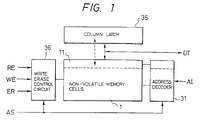
- numeral 1 indicates a group of non-volatile memory cells in which memory cells of, e.g., the MNOS (metal-nitride-oxide-semiconductor) type are disposed in an array (or matrix).
- Numeral 31 is an address decoder;
- numeral 35 is a column latch circuit which is disposed on every data line in the memory cell group 1; and
- numeral 36 is a write/erase control circuit.
- Data is written or rewritten by: applying address input signals AI to the address decoder 31, data signal DT to the memory cells 1, and a write enable signal WE to the write/erase control circuit 36.
- data (DT) may be read by applying address input signals AI and a read enable signal RE.
- Data of a designated address is erased by applying the address input signals AI and an erase enable signal ER.
- Erasure of all of the memory cells 1 ("complete" erasure) is performed by applying an all select signal AS to the address decoder 31 and the erase enable signal ER to the write/erase control circuit 36.
- AS the all select signal AS
- all the word lines in the memory cell group 1 are simultaneously selected.
- Column latches 35 are disposed on all the data lines, enabling data items to be collectively written in every row address.
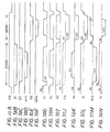
- Fig. 7A - Fig. 7 E are time charts of a write or rewrite operation for the memory described in Fig. 6.
- the operation of writing data into the memory cells 1 is initiated by applying address input signals AI, data signals DT and a write enable signal WE.
- the internal mode of operation of the memory cell (group 1) is brought into a read status by the write/erase control circuit 36, and all data items at a designated row address are fetched and saved in the column latches 35. While the data inputs (i.e. the data to be written) are accepted, the contents of the column latches 35 are rewritten according to input column addresses and the input data items.
- the acceptance of the data input signals ends after the lapse of a fixed time interval, for example, 500 ⁇ sec, and the internal mode of operation becomes an erase status in which all the memory cells in designated row address are erased.
- the internal mode of operation then becomes a write status in which the contents of the column latches 35 are written into the memory cells in the designated row address.
- the reading - erasing-writing operations described above are carried out as a series which ends when the collective writing of data in row address units has finished.
- the necessary timing device is provided in the write/erase control circuit 36.
- the operation of erasing data from the memory cell group 1 is started by applying the erase enable signal ER, which brings the internal mode of operation into the erase status.
- the erase enable signal ER which brings the internal mode of operation into the erase status.
- the all select signal AS is a "0"
- memory cells corresponding to a particular row address indicated by the address input signals AI are selected and erased
- the all select signal AS is a "1”
- all the memory cells are selected and erased.
- Fig. 1 The components represented in Fig. 1 are formed on a single semiconductor chip by well-known semiconductor techniques.
- an erase enable signal ER is applied and an all select signal AS is set at "1".
- a series of operations are then executed and these are as follows: First, data items at a previously-designated row address (for example, the first row 11 in Fig. 1 ) in the group 1 of non-volatile memory cells are fetched and held in column latches 35. Subsequently, the overall and simultaneous erasure of the group of memory cells 1 is performed. Thereafter, the contents of the column latches 35 are written into the row address 11 again.
- Fig. 2 is a diagram of the memory in an arrangement useful in understanding the present invention.
- Numeral 31 denotes an address decoder, numerals 321 - 329 high-voltage control circuits, numeral 33 a sense amplifier, numeral 34 an output buffer, numeral 35 the column latch, numeral 36 a write/erase control circuit, numerals 111,112,121 and 122 transistors which constitute the memory cells, and numerals 113 and 123 transistors which turn “on” and “off” the gate voltages of the memory cells.
- Input logic gates 51 - 53 are provided for the write enable signal WE and the erase enable signal ER which are applied to the write/erase control circuit 36 in the non-volatile memory of Fig. 6.
- a signal line 471 is provided which supplies a control signal from the write/erase control circuit 36 to the address decoder 31, and a line 48 for a control signal from the column latch 35 to the write/erase control circuit 36.
- the voltage conditions listed in Table 1 are applied to the sources S, isolated gates I, high-voltage word lines WH, selection word lines W, drains D and well regions WELL of the memory cells 111,112,121 and 122 where the operations of reading out data, writing "0" or "1" and erasing data are carried out.
- a power source voltage V cc (for example, 5 V) is applied to the word line W by the address decoder 31, and the high-voltage word line WH is set at 0 V through the high-voltage control circuit, thereby selecting the memory cells.
- the contents (D out ) of the cells are fetched from the drains D to data lines 25.
- the voltage V cc is applied to the word line W by the address decoder 31, and the same voltage V cc is applied from the high-voltage control circuit 321 or 322 to the high-voltage word line WH, a minus high-voltage -V pp (for example, -12 V) is applied from the high-voltage control circuit 324 to the well WELL, and the voltages-V pp /V cc are respectively applied to the data lines (D) according to whether the write data items are "0" or "1", whereby "0"/"1" can be written into selected memory cells.
- the voltage V cc is applied to one of the word lines W which corresponds to an address designated by the address decoder 31.
- the voltage -V pp is applied from the high-voltage control circuit 321 or 322 to the high-voltage word line WH corresponding to the address, and the voltage V cc is applied from the high-voltage control circuit 324 to the well WELL, whereby the contents of selected memory cells are erased.
- fetching the contents of designated row address(es) to save them in the colum latches 35, rewriting the contents of the column latches 35, erasing the contents of the selected row address, and writing the contents of the column latches 35 into the selected row address(es) are performed as a series of operations under the control of the write/erase control circuit 36. This is done in the same manner as in the circuit shown in Fig. 6.
- the present embodiment is constructed with logic gates 51-53 which are added so that the write/erase control circuit 36 also controls the address decoder 31.
- the memory is controlled so that the data items of a previously-designated row address are saved in the column latches before the erase operation and that the contents of the column latches are written into the row address after the erase operation.
- both the all select signal AS and erase enable signal ER are set at "1" so that a control signal C1 through the logic gates 51 and 52 becomes “1,” and a control signal C2 through the logic gate 53 becomes “0,”.
- an operation similar to the write or rewrite operation described above is instructed to the write/erase control circuit 36.
- the internal operation of the memory can be described by the series of operations of saving - erasing - writing.
- Fig. 3 shows the arrangement of the principal parts of the address decoder 31 of this arrangement.
- AI stands for address input signals, AS the all select signal, and CS the control signal which is the output from the write/erase control circuit 36 to the address decoder 31 (through the signal line 471).
- a signal for selecting the word line W1 or W2 is formed in accordance with the address input signals AI by gates 311 and 312.
- the first row address designated beforehand is a row address corresponding to the word line W1, and it is selected whenever the memory is in the overall and simultaneous erase operation, that is whenever the all select signal AS is in the status of a logical "1".
- the control signal CS which is supplied from the write/erase control circuit 36 becomes a logical "1" only in the erase operation and becomes a logical "0" in the save and write operations. Accordingly, in the all select status, a row address corresponding to the word line W2 is selected only in the erase operation, so that only the erasure of the data items of that address is carried out.
- Figs. 4A - 4D show the time charts of the overall and simultaenous erase operation in this arrangement.
- the memory may be constructed so that data inputs are accepted in the save operation and that the contents saved in the column latches 35 are written again. Alternatively, it may be constructed so that the data inputs are inhibited, in other words, so that rewriting is inhibited. This type of construction is appropriate in cases where the stored contents are secret and require protection.
- the arrangement in Fig. 2 is constructed so that protected information is included in the contents saved in the column latches 35, and the saved contents that are rewritten after the overall and simultaneous erasure are selected according to the content of the protected information.
- the protected information is stored in the memory cell 112, and the data held in the column latch 35 corresponding to the memory cell 112 is supplied to the write/erase control circuit 36 by the signal line 48 so as to make the operation thereof different.
- Fig. 5 shows the flow chart of a control process which is executed by the write/erase control circuit 36 in the overall and simultaneous erase operation of the present arrangement.
- the contents of a designated address are first saved in the column latches at a step S1. Subsequently, whether protective information is "0" or "1" is decided at a step S2. If the decided result is "0,” all the memory cells are simultaneously erased at a step S3. Thereafter, the contents of the column latches are written into the designated address again at a step S4. In contrast, if the decided result at the step S2 is "1," the control process shifts to a step S5 and ends upon performing only the overall and simultaneous erasure.
- erasure in word line unit (row address unit) can be performed in the same manner as in Fig. 6.
- a memory capacity in which the stored contents are conservable can be increased in such a way that a plurality of column latch trains are provided and that the save and rewrite operations described before are carried out a plurality of times.
- the arrangement fails to conserve the stored contents in a case where the power source voltage lowers or is cut off after the start of the overall and simultaneous erasure and before the end of the rewriting.
- a capacitor for backup is provided so as to hold necessary electric power therein, whereby the memory keeps operating even after the lowering or cutoff of the power source voltage, and the conservation can be effected.
- a non-volatile memory cell is further provided outside the group of memory cells 1, and only the fact of the occurrence of the lowering or cutoff of the power source voltage before the end of the writing is recorded in the non-volatile memory cell so as to inhibit all the subsequent operations.
- the capacity of the capacitor can be made small, and the protection of secrecy can be achieved.
- a period of time required for the erasing and the writing is 10 - 50 msec, and the lowering or cutoff of the power source voltage will, in general, pose no problem.
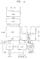
- Fig. 8 shows a block diagram of an EEPROM device which is the first embodiment of this invention.
- various circuit blocks in the figure are formed on a single semiconductor substrate such as single-crystal silicon though this is not especially restrictive.
- a memory array M-ARY is divided into a memory block MBO which is enabled to write and rewrite (also erase) data in ordinary operating statuses, and a memory block MB1 which is inhibited from writing and erasing data.
- the memory block MB1 is used as a storage area for data to-be-protected by having the write and erase operations inhibited as stated above.
- the memory array M-ARY includes a plurality of non-volatile memory cells which are arranged in the shape of a matrix, a plurality of word lines which are laterally extended, and a plurality of data lines which are vertically extended.
- the memory blocks MB0 and MB1 are so defined that some of the plurality of word lines belong to the memory block MB0, while the others belong to the memory block MB1.
- address signals which are supplied from external terminals AX0 - AXm are fed to an X-address buffer XADB.
- the X-address buffer XADB forms complementary internal address signals which consist of internal address signals inphase with the received signals and internal address signals antiphase thereto and which are supplied to an X-address decoder circuit XDCR.
- the address buffer XADB transmits predetermined address signals to a decoder DEC in order to identify accesses to the memory blocks MB0 and MB1.
- the X-address signals axm and axm-1 of the upper 2 bits are supplied to the decoder DEC and decoded therein.
- the X-address decoder circuit XDCR decodes the complementary internal address signals, and performs the operation of selecting one of the word lines.
- the non-volatile memory cell requires comparatively high voltages which differ from a voltage for the read operation thereof. Therefore, the X-address decoder circuit XDCR decodes the internal complementary address signals, and in accordance with a control signal C1 (or control signals) supplied from a control circuit CONT, it selects the word line of the memory array M-ARY under the state of the comparatively high voltage in the erase or write operation and brings the same into a selected status under the state of the comparatively low voltage in the read operation.
- address signals which are supplied from external terminals AY0 - AYn are fed to a Y-address buffer YADB.
- the Y-address buffer YADB forms complementary internal address signals which consist of internal address signals inphase with the received signals and internal address signals antiphase thereto and which are supplied to a Y-address decoder circuit YDCR.
- the Y-address decoder circuit YDCR decodes the complementary internal address signals, and performs the data line select operation of connecting at least two of the data lines to an input/output circuit I/O in order to write/read data in plural-bit unit.
- the memory array M-ARY includes a Y-gate or column switch circuit by which two or more of the data lines are selectively connected to a plurality of common data lines connected to the input/output circuit I/O. Since the non-volatile memory cell needs to supply a comparatively high voltage to the data lines in the write operation thereof, the Y-address decoder circuit YDCR has the function of forming select signals at the high voltage.
- the input/output circuit I/O includes a writing circuit which receives write signals supplied from external terminals D0 - D7 in, for example, 8-bit unit and transmits them to the data lines to-be-selected, and a reading circuit by which data items read out in 8-bit unit are delivered to the external terminals D0 - D7.
- the writing circuit and reading circuit included in the input/output circuit I/O are selectively brought into an operating status in accordance with a control signal C3 (or control signals) which is supplied from the control circuit CONT.
- control circuit CONT receives control signals supplied from external terminals, for example, a chip enable signal CE , an output enable signal OE and a write enable signal WE , as well as a writing high voltage -Vpp, and it identifies an operation mode and generates control signals and timing signals corresponding thereto.
- control signals supplied from external terminals for example, a chip enable signal CE , an output enable signal OE and a write enable signal WE , as well as a writing high voltage -Vpp, and it identifies an operation mode and generates control signals and timing signals corresponding thereto.
- the control circuit CONT executes the following three operatins in time series before the execution of the operation of writing data items into memory cells, though they are not especially restrictive: They are the first operation in which the stored information items of memory cells belonging to a word line to be selected are fetched and are held in latch circuits disposed in correspondence with data lines, the second operation in which the data items to be written are substituted into the latch circuits, and the third operation in which the erase operations of the memory cells corresponding to the word line are performed. Thereafter, it is carried out as the fourth operation that the data items held in the latch circuits are actually written into the memory cells corresponding to the word line.
- the control circuit CONT includes a timer circuit for executing the respective operations time-serially. Owing to such operations, the EEPROM can be externally accessed similarly to a static RAM.
- a register REG is disposed in order to add the function of selectively inhibiting the operations of erasing and writing data from and into the memory blocks MB0 and MB1 as described above.
- the register REG has 2-bit stored information consisting of a write inhibit signal WI and an erase inhibit signal EI.
- the write inhibit signal WI is supplied to the control circuit CONT. Even when the write enable signal WE supplied from the external terminal to the control circuit CONT is at a low level instructive of the write operation, this control circuit CONT invalidates the acceptance of the supplied signal in a case where the write inhibit signal WI indicates a status inhibiting the write operation. That is, the write inhibit signal WI is preferred to the write enable signal WE .
- the erase inhibit signal EI and the output signal of the decoder DEC are supplied to an OR gate circuit G1.
- the output signal EI' of the OR gate circuit G1 is supplied to the control circuit CONT. In a case where this signal EI' indicates a status inhibiting the erase operation, the control circuit CONT does not execute the erase operation even when the erase mode is instructed by the combination of the control signals or when the erase operation during the write operation stated before is encountered.
- the register REG is selected by setting one or more specified address terminals at a level higher than the ordinary high level, and the information items to be held are supplied from any two of the data terminals D0 thru D7.
- the address terminal or terminals By setting the address terminal or terminals at the voltage higher than the ordinary high level as stated above, the assignment of a special address to the register REG is dispensed with in an arrangement for designating this register REG, and the operation of selecting the register can be distinguished from the select operation of the memory array M-ARY.
- the control signals WI and EI may well be supplied from external terminals. Further, in a case where the EEPROM is built in a microcomputer of single chip, the control signals WI and EI can be supplied from the predetermined register of the microcomputer.
- the control signals WI and EI are basically signals which instruct the write inhibit and erase inhibit for all the cells of the memory array M-ARY without the distinction between the memory blocks MBO and MB1. In the ordinary operating statuses, therefore, both the signals WI and EI are held in reset statuses (logic "0").
- the controls with such signals WI and EI are effective for, e. g., the overall protection of the stored data items of the memory array M-ARY in a specified operating status.
- a read inhibit signal RI may well be provided in the register REG at need, thereby to add the function of selectively inhibiting the read operation. Regarding this function of selectively inhibiting the read operation, reading data items which need to be kept secret can be inhibited in such a way that an identifying code, for example, is included in a procedure for clearing the read inhibit signal (for establishing a readable status).
- Fig. 9 shows a circuit diagram of one embodiment of the memory array M-ARY as well as the decoder circuit of the EEPROM illustrated in Fig. 8.
- Fig. 9 depicts only one input terminal D in , only one output terminal D out and circuit portions associated with them. Although the other seven input and output terminals and circuit portions associated therewith are not shown, they have arrangements similar to those depicted in Fig. 9. In this regard, however, the control circuit CONT and an oscillator circuit OSC are common to the eight unit portions (each of which is constructed of the input terminal, the output terminal and the associated circuit portions).
- the EEPROM device is operated by a comparatively low power source voltage V cc of, e. g., +5 V and a minus high voltage -V pp of, e. g., -12 V which are supplied from outside the device.
- the X-address decoder XDCR, etc. constituting the selection circuit are constructed of CMOS circuits.
- the CMOS circuits are operated by being fed with the comparatively low power source voltage V cc of, e. g., +5 V. Accordingly, select/unselect signals which are formed by the address decoders XDCR and YDCR have their high level set at substantially +5 V and their low level set at substantially 0 V being the ground potential of the circuitry.
- the whole illustrated device is formed on a semiconductor substrate made of, e. g., N-type single-crystal silicon.
- An MNOS transistor is of the N-channel type, and it is formed on a P-type well region or P-type semiconductor region formed in the surface of the semiconductor substrate.
- An N-channel type MOSFET is similarly formed on the P-type semiconductor region.
- a P-channel type MOSFET is formed on the semiconductor substrate.
- one memory cell is constructed of one MNOS transistor and two MOSFET's connected in series therewith.
- the MNOS transistor and the two MOSFET's are configured into, for example, a so-called stacked gate structure in which the gate electrodes of the two MOSFET's overlap the gate electrode of the MNOS transistor, respectively.
- the MNOS transistor and the two MOSFET's constituting the memory cell are, in effect, made a unitary structure, so that the size of the memory cell is reduced.
- the memory cells are formed on a common well region.
- An N-channel MOSFET for constructing the CMOS circuit such as the X-decoder or Y-decoder is formed on a P-type well region which is independent of the common P-type well region for the memory cells.
- the N-type semiconductor substrate forms a body gate common to a plurality of P-channel MOSFET's which are formed thereon, and it is set at the level of the power source voltage V cc of the circuitry.
- a well region as the body gate of an N-channel MOSFET for constructing the CMOS circuit is maintained at the ground potential, 0 V of the circuitry.
- a memory array M-ARY includes a plurality of memory cells which are arranged in the shape of a matrix.
- One memory cell is constructed of an MNOS transistor Q2, an addressing MOSFET Q1 which is interposed between the drain of the transistor Q2 and a data line (bit line or digit line) D1, and an isolating MOSFET Q3 which is interposed between the source of the MNOS transistor Q2 and a common source line though this is not especially restrictive.
- the channel forming regions of the MOSFET's Q1 and Q3 are directly adjacent to the channel forming region of the MNOS transistor Q2. Therefore, it is to be understood that the drain and source of the MNOS transistor Q2 are terms for convenience' sake.
- the gates of the respective addressing MOSFET's Q1 etc. of the memory cells arranged in an identical row are connected to the first word line W11 in common, and the gates of the MNOS transistors Q2 etc. corresponding thereto are connected to the second word line W12 in common.
- the gates of the addressing MOSFET's and MNOS transistors of the memory cells arranged in another identical row are respectively connected to the first word line W21 and second word line W22 in common.
- the drains of the addressing MOSFET's Q1 etc. of the memory cells arranged in an identical column are connected to the data line D1 in common.
- the drains of the addressing MOSFET's of the memory cells arranged in another identical column are connected to a data line D2 in common.
- the sources of the isolating MOSFET's Q3 etc. in the memory cells are made common, to construct the common source line CS.
- the memory array M-ARY of this embodiment is operated essentially by potentials to be explained below.
- the potential V w of the well region WELL is set at a low level which is substantially equal to 0 volt being the ground potential of the circuitry.
- the common source line CS is set at the low level which is substantially equal to the ground potential.
- a control line coupled to the gates of the isolating MOSFET's Q3 is set at a high level which is substantially equal to the power source voltage V cc , so as to bring these MOSFET's Q3 into "on" statuses.
- the second word lines W12 - W22 each of which is coupled to the gate electrodes of the corresponding MNOS transistors, are set at a potential substantially equal to the ground potential, that is, a voltage intermediate between the high threshold voltage and low threshold voltage of the MNOS transistors.
- the first word line to be selected from among the first word lines W11 - W21 is brought to a select level or high level which is substantially equal to the power source voltage V cc , whereas the remaining first word lines, namely, unselected word lines are held at an unselect level or low level which is substantially equal to the ground potential.
- the data line to be selected from among the data lines D1 - D2 is fed with a sense current.
- this memory cell forms a current path for the data line with which it is coupled. If the MNOS transistor in the selected memory cell has the high threshold voltage, this memory cell forms, in effect, no current path. Accordingly, the data of the memory cell is read out by detecting the sense current.
- the well region WELL is set at a minus high voltage which is substantially equal to -V pp
- the control line coupled to the gate electrodes of the isolating MOSFET's Q3 is set at a minus high potential so as to bring these MOSFET's Q3 into "off" statuses.
- the first word lines W11 - W21 is set at the unselect level or low level which is substantially equal to the ground potential.
- One of the second word lines W12 - W22 is brought to a select level which is substantially equal to the power source voltage V cc , whereas the remaining second word lines are held at a minus high voltage which is close to the voltage -V pp .
- the data lines are set at a high level substantially equal to the power source voltage V cc or a low level having a minus high voltage close to the minus voltage -V pp , in accordance with data items to be written into the memory cells.
- the well region WELL and the common source line CS are set at an erase level or high level which is substantially equal to the power source voltage V cc .
- the first word lines W11 - W21 and the second word lines W12 - W22 are basically set at the level substantially equal to the power source voltage V cc of the circuitry and the level substantially equal to the voltage -V pp , respectively. According to this embodiment, however, the levels of the first and second word lines are determined so as to permit the memory cells to be erased every memory row though this is not especially restrictive.
- the first word line corresponding to the memory row which needs to be erased is set at an erase level substantially equal to the power source voltage V cc
- the first word lines corresponding to the memory rows which need not be erased are set at an unerase level substantially equal to the ground potential of the circuitry.
- the second word lines W12 - W22 the second word line corresponding to the first word line which is set at the erase level is brought to an erase level substantially equal to the minus voltage -V pp
- the second word lines corresponding to the first word lines which are set at the unerase level are held at an unerase level substantially equal to the power source voltage V cc .
- the body gates of the N-channel MOSFET's constituting the CMOS circuits need to be set at a potential of, for example, 0 volt independently of the body gates of the MNOS transistors.
- the body gates of the memory cells namely, the semiconductor region WELL formed with the memory array M-ARY are/is electrically isolated from the semiconductor region (well region) in which the N-channel MOSFET's constituting the peripheral circuits such as X-decoder and Y-decoder are formed.
- the first and second word lines W11 - W21 and W12 - W22 are driven by the X-decoder XDCR.
- the X-decoder XDCR is composed of a plurality of unit decoder circuits which correspond to the memory rows of the memory array M-ARY in one-to-one relationship.
- one unit decoder circuit is constructed of a NOR gate circuit NOR1 receiving address signals, a gate circuit G and a level conversion circuit LVC.
- the gate circuit G is so constructed as to transmit the output of the corresponding NOR gate circuit to the corresponding first word line in, at least, the read operation and to set the first word line at the level substantially equal to the ground potential of the circuitry irrespective of the output of the corresponding NOR gate circuit in the write operation.
- the gate circuit G in order to permit the selective erase operation stated before, is so constructed as to transmit the output of the corresponding NOR gate circuit to the corresponding first word line in the erase operation besides in the read operation.
- the level conversion circuit LVC brings the corresponding second word line to the select level substantially equal to the power source voltage V cc in response to the fact that the output of the corresponding NOR gate circuit is the select level of the high level, and it brings the second word line to the unselect level substantially equal to the minus voltage -V pp in response to the fact that the output of the NOR gate circuit is the unselect level of the low level.
- the level conversion circuit LVC brings the corresponding second word line to the erase selection level substantially equal to the minus voltage -V pp in response to the fact that the output of the corresponding NOR gate circuit is the select level of the high level, and it brings the second word line to the erase unselection level substantially equal to the power source voltage V cc in response to the fact that the output of the NOR gate circuit is the unselect level of the low level.
- the gates of the isolating MOSFET's Q3 etc. are coupled in common to the control line which is supplied with a control voltage V ig formed by a control voltage generator circuit V ig -G.
- the sources of these isolating MOSFET's Q3 etc. are made common to construct the common source line CS.
- the control voltage V ig which is supplied to the isolating MOSFET Q3 is set at a low potential of, e.
- the MOSFET Q3 may be brought into the "off" status when one of the second word lines W12 - W22 with which the memory cell to be selected is coupled is set at the high level (5 V), the well region WELL as the body gate is set at about -12 V and the data line, for example, D1 is set at about -10 V.
- the data line D2 is set at the high level of, e. g., +5 V, current is prevented from flowing from the data line D2 to the side of the memory cell into which the data is to be written.
- the common source line CS is coupled to the output terminal of a common source line driver circuit DVR.
- the driver circuit DVR may have such output characteristics that, in the erase operation, the common source line CS can be driven to the level substantially equal to the power source voltage V cc , while in the read operation, the common source line CS can be driven to the level substantially equal to the ground potential of the circuitry.
- the junction between the well region WELL and the electrode of the MOSFET Q3 coupled to the common source line CS can be prevented from being forward-biased.
- a current path required for the read operation can be formed between the common source line CS and the ground point of the circuitry.
- the driver circuit DVR is constructed, as shown in Fig. 9 , of a MOSFET Q6 which is interposed between the power source terminal V cc of the circuitry and the common source line CS, MOSFET's Q7 and Q8 which are connected in parallel between the common source line CS and the ground point of the circuitry, and a CMOS inverter circuit IV.
- the gates of the MOSFET's Q7 and Q8 are supplied with a control signal er, and the gate of the MOSFET Q6 with a signal obtained by inverting the control signal er by means of the inverter circuit IV.
- the MOSFET's Q7, Q8 and the MOSFET Q6 are complementarily turned “on” and “off” in accordance with the level of the control signal er.
- the control signal er is set at a high level substantially equal to the power source voltage V cc , so as to bring the MOSFET Q6 into the "on” status and the MOSFET's Q7 and Q8 into the "off" statuses in the erase operation, and it is set at a low level substantially equal to 0 volt, in the read and write operations.
- the control signal er has its output timing controlled in correspondence with the change timing of the potential of the well region WELL in order that PN-junctions defined by the MOSFET's etc. formed in the well region may be prevented from falling into forward-biased statuses.
- MOSFET's Q4 and Q5 are respectively interposed between the second word lines W12 and W22 and the common source line CS. These MOSFET's Q4 and Q5 are switched and controlled by a control signal er/we .
- the control signal er/we has its high level set at a level substantially equal to the power source voltage V cc and has its low level set at a level substantially equal to the ground potential.
- the MOSFET's Q4 and Q5 are made the P-channel type so as to be favorably turned “off” even when the minus potential is applied to the corresponding second word lines W12 and W22.
- the switching MOSFET's Q4 - Q5 are brought into "on" statuses so as to short-circuit the gates of the MNOS transistors Q2 etc. and the common source line CS thereby to equalize the potentials of them.
- These switching MOSFET's Q4 - Q5 are interposed between the corresponding second word lines and the common source line CS, for the following reason:
- the MOSFET's Q7 and Q8 in the driver circuit DVR are brought into the "on" statuses in the read operation in accordance with the control signal er which is set at the low level substantially equal to 0 volt.
- the MOSFET's Q7 and Q8 have unnegligible "on” resistances though they are connected in parallel as shown in the figure.
- the common source line CS has its potential raised by a current which flows through the resistances in the read operation.
- the MOSFET's Q7 and Q8 are of the P-channel type, they do not have a driving ability sufficient for changing the common source line CS to the ground potential of the circuitry, and hence, the floating magnitude of the potential of the common source line CS becomes large. More specifically, the current transfer electrodes of the MOSFET's Q7 and Q8 coupled to the common source line CS act as source electrodes with respect to a plus potential which is applied through the memory array M-ARY as well as the common source line CS. Therefore, the MOSFET's Q7 and Q8 are substantially turned “off" when the common source line CS becomes a potential below the threshold voltages of the respective MOSFET's.
- Such rise in the potential of the common source line CS incurs increase in an effective threshold voltage attributed to the substrate effect of the MNOS transistor, and lowers the conductance of the MNOS transistor which ought to have the low threshold voltage. In other words, a read current which flows through the MNOS transistor having the low threshold voltage is reduced.
- the short-circuiting MOSFET's Q4 and Q5 render the potentials of the corresponding second word lines W12 and W22 substantially equal to the potential of the common source line CS in the read operation, thereby to prevent the increase of the effective threshold voltage of the MNOS transistor.
- the well region WELL in which the memory array M-ARY is formed is supplied with the control voltage V w which is formed by a control voltage generator circuit V w -G.
- This voltage V w is set at a minus high voltage of, e. g., about -12 V in the write operation, at a potential of about +5 V in the erase operation, and at about 0 V at any other time.
- the respective data lines D1 and D2 of the memory array M-ARY are provided with N-channel MOSFET's Q11 and Q12 which electrically isolate these data lines D1 and D2 from corresponding column switch MOSFET's Q9 and Q10. More specifically, the MOSFET's Q11, Q12 etc. and the N-channel MOSFET's Q9, Q10 etc. as a Y gate (column switch) circuit C-SW are respectively interposed in series form between the corresponding data lines D1, D2 etc. and the common data line CD.
- the data line isolating MOSFET's Q11 - Q12 are formed in the same P-type well region WELL as that of the MNOS transistors.
- the gates of these MOSFET's Q11 - Q12 are supplied with a control voltage V c which is formed by a control voltage generator circuit V c -G.
- This control voltage V c is set at a minus high voltage of, e. g., -12 V in only the status of the write operation, and at a high level of, e. g., the power source voltage V cc in the other statuses of the read and erase operations.
- the MOSFET's Q11 - Q12 are turned “off” in the status of the write operation.
- the MOSFET's Q11 - Q12 are turned “off” in the status of the erase operation in accordance with the fact that the well region WELL is set at the high level of, e.
- the MOSFET's Q11 - Q12 are turned “on” only in the status of the read operation.
- the MOSFET's Q11, Q12 etc. are held in the "off" statuses in the write operation, so that even when the potentials of the data lines are brought to the minus high voltage, the nodes between the MOSFET's Q11, Q12 etc. and the column switch MOSFET's Q9, Q10 etc. to be explained below are held in floating statuses.
- the sources and drains of the switch MOSFET's Q9, Q10 etc. coupled to the mutual nodes and the well region in which these MOSFET's are formed can be prevented from being forward-biased.
- the gates of the MOSFET's Q9 - Q10 constituting the column switch circuit C-SW are supplied with the output signals of a Y-decoder YDCR.
- the outputs of the Y-decoder YDCR are set at a select level substantially equal to the power source voltage V cc or at an unselect level substantially equal to 0 volt.
- the common data line CD is coupled to the output terminal of a data input circuit DIB which constitutes an input/output circuit IOB, and to the input terminal of a data output circuit DOB which is composed of a sense amplifier SA and an output buffer circuit OBC.
- the input terminal of the data input circuit and the output terminal of the data output circuit constituting the input/output circuit IOB are coupled to an external terminal I/O.
- each of the data lines D1 - D2 is provided with a latch circuit FF which serves to hold preceding stored information before an erase/write mode, and with a level conversion circuit LVC which brings the potential of the data line to the minus high voltage -V pp selectively according to the stored information of the latch circuit FF in the write operation.
- LVC level conversion circuit
- the control circuit CONT receives the chip enable signal, write enable signal and output enable signal respectively supplied to the external terminals CE , WE and OE and the write voltage supplied to the external terminal -V pp as stated before. Thus, it discriminates various operation modes and produces various control signals for controlling the operations of the circuits such as the gate circuits G, level conversion circuits LVC, control voltage generator circuits V ig -G, V c -G and V w -G, driver circuit DVR, data input circuit DIB and data output circuit DOB.
- the control signals which are formed by the control circuit CONT principal ones are illustrated in Fig. 9.
- the waveform diagrams of the principal control signals are exemplified in Fig. 10A- Fig. 10N.
- a read operation mode is instructed by the low level, low level and high level of the respective signals (hereinbelow, expressed as signals CE , WE and OE ) at the external terminals CE , WE and OE
- a standby operation mode is instructed by the high level of the signal CE .
- the first write operation mode for writing data items into the latch circuits FF in Fig. 9 is instructed by the low level, low level, high level and low level of the respective signals CE , WE , OE and -V pp
- the second write operation mode for writing data items into the memory cells is instructed by the low level, low level, high level and high level of the respective signals CE , WE , OE and -V pp .
- An erase operation is instructed for a predetermined interval when the second write operation mode has been instructed.
- the various control signals to be delivered from the control circuit CONT are provided in time series in accordance with this embodiment.
- the oscillator circuit OSC in Fig. 9 is operated by the power source voltage V cc of, e. g., +5 volts which is applied between the external terminals V cc and GND of the EEPROM device. If necessary for lowering the power consumption of the circuitry, it is also allowed to control the oscillator circuit OSC so as to operate only when the write voltage is applied to the terminal -V pp by way of example.
- the first write mode not illustrated is carried out before the second write mode.
- the stored information items of all the memory cells coupled to one addressed word line are once fetched and are held in the latch circuits FF shown in Fig. 9 .
- a data signal supplied from the external terminal is put into the latch circuit corresponding to the data line of the memory cell into which the data item is to be written.
- the Y-addresses are sequentially switched, whereby the write signals composed of a plurality of bits and supplied from the external terminal are sequentially put into the respectively corresponding latch circuits.
- the second write mode illustrated in the charts is carried out.
- the erase operations of the MNOS transistors coupled to the word line are performed, whereupon the memory cells for one word line are simultaneously subjected to write operations in accordance with the information items of the latch circuits. Owing to the above operations, a write operation which is similar to that of a static RAM when viewed from outside can be executed.
- a control signal EW is raised from a low level to a high level.
- Internal signals er , ert and erts are respectively changed from high levels to low levels with predetermined time differences since the rise of the signal EW to the high level.
- the MOSFET Q6 of the driver circuit DVR in Fig. 13 is brought into the "on" status by the low level of the internal signal er (high level of er), so that the common source line CS of the memory array M-ARY is set at the high level of, e. g., +5 V.
- a reset signal cr is changed from +5 V to a low level of, e. g., -4 V at which it is temporarily held.
- the output terminals of the level conversion circuits LVC (the word lines W12 etc.) are reset to the ground potential and are thereafter set at the low level (0 V) in the floating statuses.
- a reset signal cu is changed from +5 V to a low level of, e. g., -4 V at which it is temporarily held.
- loads having comparatively large parasitic capacitances such as the well WELL and isolating MOSFET's, are subjected to reset operations similar to the above.
- the X-decoder XDCR starts the level changing operation thereof.
- the potential of the selected second word line in other words, the gate potentials of the MNOS transistors to be erased is/are lowered to the minus high voltage of about -10 V as explained before.
- the potentials of the word lines not to be selected, in other words, the gate voltages of the MNOS transistors to be inhibited from the erase operations are set at the high level of, e. g., +5 V as understood from the above-stated operations though this situation is not illustrated.
- control voltage generator circuit V w -G for forming the drive voltage of the body gate of the memory array M-ARY sets its voltage V w at the high level of, e. g., +5 V in response to the low level of the internal signal erts .
- the minus high voltage is supplied between the body gate and the gates of the MNOS transistors coupled to the selected word line.
- information charges gathered in the floating gates of the MNOS transistors are restored into the body gate by the tunnel effect based on the high electric field.
- the body gate and the gates of the MNOS transistors coupled to the unselected word lines are held at the identical potential, the erase operations of these MNOS transistors are not performed.
- the internal signals are respectively changed from the low levels to the high levels with time differences in the order of erts , ert and er reverse to the order for the start of the erasure. Consequently, the original statuses are restored in the order of the well region WELL, the second word line and the data lines.
- reset signals cr , cu and cw are formed by the aforementioned internal signals.
- the control voltage generator circuit V w -G brings its voltage V w to the minus high voltage -V pp of, e. g., -12 V.
- the well region WELL formed with the memory array M-ARY is first lowered to the minus high voltage -V pp .
- the control voltage generator circuit V ig -G brings its voltage V ig to the minus high voltage of, e. g., about -12 V.
- the isolating MOSFET's of the memory cells are turned “off.”
- the voltage V c is brought to the minus high voltage of, e. g., -12 V as stated above.
- the data line isolating switch MOSFET's Q11 - Q12 are turned “off.”
- the gate circuits G of the X-decoder XDCR are enabled in accordance with the low level of the internal signal we ', whereby the first word line of the selected memory cells is set at the high level (+5 V), and the unselected word lines are set at the ground potential (0 V) of the circuitry (not illustrated).
- the X-decoder XDCR brings the selected second word line to the high level (+5 V) and the unselected ones to the low level.
- the level conversion circuits LVC bring the corresponding second word line to the high level of, e. g., +5 V for the select signal of the high level and the corresponding second word lines to the minus high voltage of, e. g., -10 V for the unselect signals of the low level though the latter case is not illustrated.
- the level conversion circuits LVC coupled to the respective data lines are brought into operating statuses.
- the level conversion circuit to write logic "1" is set at the minus high voltage of about -10 V
- the level conversion circuit to write logic "0" (to be inhibited from writing) is set at the high level of about +5 V.
- the gate voltage becomes about +5 V
- the voltage of the body gate (well region WELL) becomes about -12 V
- the drain (data line) voltage becomes about -10 V, so that a high electric field of, e. g., about 15 V acts between the channel in the body gate and the gate electrode, and electrons are injected by the tunnel effect.
- the drain voltage is brought to about +5 V, so that no high voltage is applied between the gate and the channel, and the injection of electrons does not take place.
- the internal signals are respectively changed from the low levels to the high levels with a time difference in the order of wets and we ' reverse to the order for the start of the write operation. Consequently, the original statuses are restored in the order of the data lines as well as the second word lines and the well region.
- the reset signals cr , cu and cw are formed by the aforementioned internal signals.
- the control circuit CONT inhibits the memory block MB1 from the erase operation by the use of the signal formed by the decoder DEC, irrespective of the erase inhibit signal EI. That is, even when the memory block MB1 is addressed and is instructed to rewrite data, the erase operation is inhibited, so that only the write operation is performed. In other words, the various control signals for the erase operation shown in Figs. 10A - 10N are not generated, so that only the write operation is validated and executed. More specifically, in response to the erase inhibit signal EI' rendered the high level, the control circuit CONT forms various signals indicated by broken lines in an erase period shown in Figs. 10A - 10N.
- the control circuit CONT forms signals indicated by solid lines in a write period.
- the erase operation is inhibited, and only the write operation is executed.
- only the first write operation is, in effect, validated for the memory block MB1.
- data to be protected for example, a normal identifying code or ID information
- the erasure is inhibited, with the result that merely a change from the logic "1" (unwritten status) to the logic "0" (written status) is executed by the write operation.
- the identifying code or ID information be unit data composed of 8 bits.
- the number of the bits of the logic "0" is determined to be four in the unit data. Then, when the unlawful rewriting as exemplified above has been done, the logic "1" in the remaining 4 bits is changed to the logic "0," and the number of bits of the logic "0" exceeds 4.
- the identifying code or ID information etc.
- one identifying code or ID information is constructed of a plurality of data items, for example, 8 bytes, in which the summation of "0's" may be set at a number of 32.
- control circuit CONT is additionally provided with the function of instructing the overall erasure and the function of responsively invalidating the erase inhibit signal EI' delivered from the gate circuit G1.
- control circuit CONT is supplied with the write inhibit signal WI.
- the control circuit CONT forms various signals indicated by dot-and-dash lines in the write period shown in Figs. 14A - 14N.
- FIG. 11 Shown in Fig. 11 is a block diagram of an EEPROM device which is the second embodiment of this invention.
- the memory block MB1 is inhibited from erasure, and hence, the write/ erase operation tests of the memory block MB1 are inconvenient. According to this embodiment, therefore, the EEPROM in Fig. 8 is further furnished with circuits to be explained below:
- a decision circuit LOG is disposed which receives the signal of the internal signal line (common data line) between the memory array M-ARY and the input/output circuit I/O.
- This decision circuit LOG has the function of counting the number of "0's” in unit data read out of the memory array M-ARY.
- the number of "0's” in the unit data written in the memory block MB1 is set at 4 as described before.
- the decision circuit LOG forms a decision signal ER which is set at a high level (logic "1") when the number of "0's” in the read data is at least 4, and which is set at a low level (logic "0") when the number of "0's” is less than 4.
- This decision signal ER is supplied to one input of an AND gate circuit G2, the other input of which is fed with the output signal of the decoder DEC, as the control signal of the gate circuit G2.
- the output signal of the AND gate circuit G2 is supplied to one input of the OR gate circuit G1, the other input of which receives the erase inhibit signal EI from the register REG.
- the write test or erase test for the memory block MB1 can be conducted at will in such a way that the number of "0's" in data to be written is set to be less than 4. After the end of such tests, when data to be protected is written, the number of "0's" in unit data may be set at 4 as explained before.
- the addition of the decision circuit LOG and gate circuit G2 of comparatively simple arrangement makes it possible to easily perform the rewrite test of the memory block MB1 which is inhibited from the erase operation.
- the decision circuit can be endowed with the function of informing the exterior of the fact that data has been illicitly written. More specifically, the function of detecting that the set number of logical "0's" (4 in the above example) is exceeded is added as a count deciding function, and an alarm signal indicative of the illicit writing is generated.
- circuit blocks and the internal circuits and operations thereof omitted from the above description are similar to those elucidated with reference to Fig. 8 - Fig. 10N.
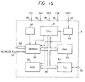
- Fig. 12 shows the third embodiment of the present invention.
- This embodiment is a single-chip microcomputer for an IC card in which the EEPROM of the first or second embodiment stated above is built.
- circuit blocks enclosed with a dot-and-dash line A in the figure are formed on one semiconductor chip such as single-crystal silicon substrate.
- the single-chip microcomputer of this embodiment includes a microprocessor unit (hereinbelow, termed “CPU”) 81 which controls the internal execute unit etc. thereof in accordance with programs so as to perform desired processes, a read only memory (ROM) 82 in which the operation program of the CPU 81, etc. are stored, a random access memory (RAM) 83 which principally offers the working area of the CPU 81, and a serial communication interface 84 which sends and receives data to and from an external apparatus such as terminal equipment, these circuits being interconnected through an internal system bus 85.
- CPU microprocessor unit
- ROM read only memory
- RAM random access memory
- serial communication interface 84 which sends and receives data to and from an external apparatus such as terminal equipment, these circuits being interconnected through an internal system bus 85.
- the read only memory 82 is constructed of an unrewritable masked ROM into which data is written by masking in the course of a manufacturing process.
- An EEPROM 86 in which data items proper to a user, such as the money information of a bank and the identifying code of the individual, are stored, and a booster circuit 87 which generates a write voltage V pp required in the operation of writing the data items into the EEPROM 86, are packaged on the chip A separately from the masked ROM 82.
- the EEPROM 86 is so constructed that it can be usually accessed by only the CPU 81.
- the IC card is provided with a testing bus 88 separately from the internal system bus 85, and with a mode setting circuit 89 for making it possible to access the EEPROM 86 from outside directly without the intervention of the CPU 81 in accordance with an external control signal TEST and by the use of the testing bus 88, as well as a terminal 90 for inputting the mode control signal TEST.
- This terminal 90 for mode control, and a terminal 91 for inputting a read enable signal RE, a write enable signal WE, an erase enable signal ER and an all select signal AS for the testing bus 88 as well as the EEPROM 86, are not connected to external terminals as the IC card. Connected to the external terminals of the IC card are only five terminals; an I/O terminal 92 for serial communications, power source terminals 93 and 94 for applying power source voltages V cc and V ss to the chip, respectively, an input terminal 95 for a reset signal RES, and an input terminal 96 for a clock CLK.
- the EEPROM 86 cannot be directly accessed using the testing bus 88.
- the EEPROM 86 when the EEPROM 86 is so constructed that some of data items can be conserved by rewriting even in the overall erasure mode as in the foregoing embodiment, the unlawful initialization of the EEPROM cannot be performed. Thus, it is possible to prevent the illicit use of the IC card ascribable to the alterations of the important data items in the EEPROM, such as money information and identifying code.
- the ROM 82 stores therein the instructions or programs according to which the CPU 81 executes the rewriting of data for the EEPROM 86 in the ordinary operation modes.
- the IC card can also be so constructed that the CPU 81 cannot access the first row address or a designation row address containing protective information.
- the control signals such as the read enable signal RE, write enable signal WE and erase enable signal ER, which are required when data items are read out of and written into the EEPROM 86 by the CPU 81 in the ordinary modes, are afforded from the CPU 81 to the EEPROM 86.
- a microcomputer for a card can also be constructed by combining an EEPROM chip with a single-chip microcomputer in which a ROM and a RAM are built.
- an EEPROM may well be such that an erase operation and a write operation are independently designated and that a memory array is erased or written according to the designated operation.
- the first write operation mode may well be shifted to the second write operation mode automatically within an EEPROM.
- overall erasure may be carried out every memory block by dividedly isolating a well region in which a memory array is constructed.
- the capacity of a memory block in which data to be protected is stored may well be made freely designated by a master slice system.
- the memory area of the memory block MB1 can be simply changed by altering the address signals which are supplied to the decoder.
- the system for dividing memory blocks may be based on the division of data lines or based on the combination of the divisions of the word and data lines. Adopting the division of the data lines in this manner can be realized by, for example, disposing a decoder which receives address signals from a Y-address buffer or supplying a select bit to a Y-address buffer or a decoder.
- a memory array and its peripheral circuits can adopt various modifications.
- the high voltage -V pp has been described as being supplied from outside, a high voltage generator circuit may well be built in.
- the peripheral circuits constructed of the CMOS circuits may be constructed of only N-channel MOSFET's or P-channel MOSFET's.
- high voltages for writing/erasing various aspects of performance can be adopted, including a method in which a substrate formed with MNOS transistors is fixed at the ground potential of circuitry, whereupon a plus high voltage and a minus high voltage are used.
- An EEPROM according to this invention is constructed as a single non-volatile memory as in any of the embodiments, and besides, it can be comparatively simply built in a digital integrated circuit, for example, a microcomputer of single chip because a circuit scale for realizing the data protective function as stated above is small.
- the single-chip microcomputer which has the built-in EEPROM endowed with the protective function as stated above is suitable for an IC card. More specifically, the IC card needs to have its physical strength increased for the purpose of protecting a built-in semiconductor integrated circuit device.
- the single-chip microcomputer having the built-in EEPROM as described above can be realized, the physical size of the semiconductor integrated circuit device built in the IC card can be made small, so that the increase of the physical strength is simplified and that the cost of the IC card can be lowered.
- a non-volatile memory element which is electrically writable and erasable may be any other than the MNOS transistor, such as an element of FLOTOX (floating-gate tunnel oxide) structure.
- FLOTOX floating-gate tunnel oxide
- This invention can be extensively utilized for semiconductor integrated circuit devices each including a non-volatile memory circuit which is electrically writable and erasable.
Landscapes
- Engineering & Computer Science (AREA)
- Computer Security & Cryptography (AREA)
- Theoretical Computer Science (AREA)
- Physics & Mathematics (AREA)
- General Engineering & Computer Science (AREA)
- General Physics & Mathematics (AREA)
- Read Only Memory (AREA)
- Storage Device Security (AREA)
Claims (7)
- Nicht-flüchtiges Speichergerät, umfassenddadurch gekennzeichnet, daß das Gerät ferner aufweist:ein Speicher-Array (M-ARY) mit einem ersten und einem zweiten Speicherblock (MB0, MB1), deren jeder nicht-flüchtige Speicherzellen enthält,eine Steuerschaltung (CONT), die einen Löschvorgang auf dem Speicher-Array steuert,eine Wähleinrichtung (XDCR, YDCR) zum Auswählen mindestens einer nicht-flüchtigen Speicherzelle aus dem Speicher-Array,eine Bestimmungsschaltung (DEC) zum Bestimmen, ob die ausgewählte nicht-flüchtige Speicherzelle im ersten oder zweiten Speicherblock liegt,eine Registerschaltung (REG) mit einem ersten Steuerbit (EI) zur Steuerung des Löschvorgangs der Steuerschaltung auf dem Speicher-Array, wobei das erste Steuerbit selektiv einen ersten Zustand zum Verhindern und einen zweiten Zustand zum Ermöglichen des Löschvorgangs der Steuerschaltung auf dem Speicher-Array annimmt, undeine mit der Bestimmungsschaltung und der Registerschaltung gekoppelte Torschaltung (G1), die den Löschvorgang der Steuerschaltung auf dem zweiten Block unabhängig von dem zweiten Zustand des ersten Steuerbits verhindert, wenn die Bestimmungsschaltung bestimmt, daß die ausgewählte nicht-flüchtige Speicherzelle im zweiten Block liegt.
- Nicht-flüchtiges Speichergerät nach Anspruch 1, wobei jede der nicht-flüchtigen Speicherzellen ein elektrisch löschbares und programmierbares Speicherelement aufweist.
- Nicht-flüchtiges Speichergerät nach Anspruch 1 oder 2, wobei die Steuerschaltung auch einen Schreibvorgang auf dem Speicher-Array steuert und die Registerschaltung ferner ein zweites Steuerbit (WI) zur Steuerung des Schreibvorgangs der Steuerschaltung auf dem Speicher-Array aufweist, wobei das zweite Steuerbit einen dritten Zustand zum Verhindern und einen vierten Zustand zum Ermöglichen des Schreibvorgangs der Steuerschaltung auf dem Speicher-Array annimmt.
- Ein-Chip-Mikrocomputer mit einem Mikroprozessor (81) und einem nicht-flüchtigen Speichergerät nach einem der Ansprüche 1 bis 3, wobei jeder der Zustände des ersten und des zweiten Steuerbits in der Registerschaltung von dem Mikroprozessor gesetzt wird.
- Integrierte Schaltungskarte mit einem Mikrocomputer nach Anspruch 4.
- Nicht-flüchtiges Speichergerät nach Anspruch 3, wobei die Steuerschaltung einen Lesevorgang auf dem Speicher-Array steuert und die Registerschaltung ferner ein drittes Steuerbit (RI) zur Steuerung des Lesevorgangs der Steuerschaltung auf dem Speicher-Array steuert, wobei das dritte Steuerbit einen fünften Zustand zum Verhindern und einen sechsten Zustand zum Ermöglichen des Lesevorgangs der Steuerschaltung auf dem Speicher-Array annimmt.
- Nicht-flüchtiges Speichergerät nach Anspruch 1 mit ferner einer Entscheidungsstufe (LOG), die aufgrund von aus dem zweiten Speicherblock (MB1) ausgelesenen Daten ein Entscheidungssignal (ER) erzeugt und mit diesem die Torschaltung (G1) beaufschlagt, um eine Bestimmungsfunktion durch die Bestimmungsschaltung ungültig zu machen.
Applications Claiming Priority (5)
| Application Number | Priority Date | Filing Date | Title |
|---|---|---|---|
| JP5880887A JP2833621B2 (ja) | 1987-03-16 | 1987-03-16 | 不揮発性記憶装置 |
| JP58808/87 | 1987-03-16 | ||
| JP139402/87 | 1987-06-03 | ||
| JP62139402A JPS63303447A (ja) | 1987-06-03 | 1987-06-03 | 半導体集積回路装置 |
| EP88302235A EP0283238B1 (de) | 1987-03-16 | 1988-03-15 | Nichtflüchtiger Speicher |
Related Parent Applications (2)
| Application Number | Title | Priority Date | Filing Date |
|---|---|---|---|
| EP88302235A Division EP0283238B1 (de) | 1987-03-16 | 1988-03-15 | Nichtflüchtiger Speicher |
| EP88302235.2 Division | 1988-03-15 |
Publications (3)
| Publication Number | Publication Date |
|---|---|
| EP0579274A2 EP0579274A2 (de) | 1994-01-19 |
| EP0579274A3 EP0579274A3 (en) | 1995-09-20 |
| EP0579274B1 true EP0579274B1 (de) | 1998-07-08 |
Family
ID=26399812
Family Applications (2)
| Application Number | Title | Priority Date | Filing Date |
|---|---|---|---|
| EP93114480A Expired - Lifetime EP0579274B1 (de) | 1987-03-16 | 1988-03-15 | Nicht-Flüchtiger Speicher |
| EP88302235A Expired - Lifetime EP0283238B1 (de) | 1987-03-16 | 1988-03-15 | Nichtflüchtiger Speicher |
Family Applications After (1)
| Application Number | Title | Priority Date | Filing Date |
|---|---|---|---|
| EP88302235A Expired - Lifetime EP0283238B1 (de) | 1987-03-16 | 1988-03-15 | Nichtflüchtiger Speicher |
Country Status (5)
| Country | Link |
|---|---|
| US (2) | US4931997A (de) |
| EP (2) | EP0579274B1 (de) |
| KR (1) | KR950014560B1 (de) |
| DE (2) | DE3856216T2 (de) |
| HK (1) | HK28396A (de) |
Families Citing this family (74)
| Publication number | Priority date | Publication date | Assignee | Title |
|---|---|---|---|---|
| US4931997A (en) * | 1987-03-16 | 1990-06-05 | Hitachi Ltd. | Semiconductor memory having storage buffer to save control data during bulk erase |
| US5315547A (en) * | 1988-07-11 | 1994-05-24 | Hitachi, Ltd. | Nonvolatile semiconductor memory device with selective tow erasure |
| JPH0812646B2 (ja) * | 1989-03-03 | 1996-02-07 | 三菱電機株式会社 | 半導体集積回路 |
| US7447069B1 (en) | 1989-04-13 | 2008-11-04 | Sandisk Corporation | Flash EEprom system |
| EP0675502B1 (de) | 1989-04-13 | 2005-05-25 | SanDisk Corporation | EEPROM-System mit aus mehreren Chips bestehender Blocklöschung |
| JPH03232196A (ja) * | 1990-02-07 | 1991-10-16 | Toshiba Corp | 半導体記憶装置 |
| JP3099887B2 (ja) * | 1990-04-12 | 2000-10-16 | 株式会社東芝 | 不揮発性半導体記憶装置 |
| JPH04123471A (ja) * | 1990-09-14 | 1992-04-23 | Oki Electric Ind Co Ltd | 半導体記憶装置のデータ書込みおよび消去方法 |
| US5337280A (en) * | 1990-09-27 | 1994-08-09 | Oki Electric Industry Co., Ltd. | EEPROM circuit |
| JPH04141794A (ja) * | 1990-10-03 | 1992-05-15 | Mitsubishi Electric Corp | Icカード |
| JP2724046B2 (ja) * | 1991-02-07 | 1998-03-09 | 富士写真フイルム株式会社 | Icメモリカードシステム |
| US5546561A (en) * | 1991-02-11 | 1996-08-13 | Intel Corporation | Circuitry and method for selectively protecting the integrity of data stored within a range of addresses within a non-volatile semiconductor memory |
| US5309402A (en) * | 1991-02-15 | 1994-05-03 | Nec Corporation | Flash electrically erasable and programmable ROM |
| JP2837970B2 (ja) * | 1991-04-12 | 1998-12-16 | 三菱電機株式会社 | Icカード |
| US5197034A (en) * | 1991-05-10 | 1993-03-23 | Intel Corporation | Floating gate non-volatile memory with deep power down and write lock-out |
| US5270980A (en) * | 1991-10-28 | 1993-12-14 | Eastman Kodak Company | Sector erasable flash EEPROM |
| WO1993010498A1 (en) * | 1991-11-12 | 1993-05-27 | Microchip Technology Inc. | Security for on-chip microcontroller memory |
| JP3080744B2 (ja) * | 1991-12-27 | 2000-08-28 | 日本電気株式会社 | 電気的に書き込み一括消去可能な不揮発性半導体記憶装置 |
| TW231343B (de) | 1992-03-17 | 1994-10-01 | Hitachi Seisakusyo Kk | |
| DE4311358C2 (de) * | 1992-04-07 | 1999-07-22 | Mitsubishi Electric Corp | Nicht-flüchtige Halbleiterspeichereinrichtung und Betriebsverfahren für eine nicht-flüchtige Halbleiterspeichereinrichtung und Verfahren zum Programmieren von Information in eine nicht-flüchtige Halbleiterspeichereinrichtung |
| US5557572A (en) * | 1992-04-24 | 1996-09-17 | Nippon Steel Corporation | Non-volatile semiconductor memory device |
| US5473753A (en) * | 1992-10-30 | 1995-12-05 | Intel Corporation | Method of managing defects in flash disk memories |
| DE4242579C2 (de) * | 1992-12-16 | 1997-08-21 | Siemens Ag | Verfahren zur Echtheitserkennung von Datenträgern |
| US5345413A (en) * | 1993-04-01 | 1994-09-06 | Microchip Technology Incorporated | Default fuse condition for memory device after final test |
| US5363334A (en) * | 1993-04-10 | 1994-11-08 | Microchip Technology Incorporated | Write protection security for memory device |
| JPH07508121A (ja) * | 1993-05-11 | 1995-09-07 | 富士通株式会社 | 不揮発性メモリ装置,不揮発性メモリセル,並びに不揮発性メモリセルおよび複数のトランジスタの各々の閾値を調整する方法 |
| US5513136A (en) * | 1993-09-27 | 1996-04-30 | Intel Corporation | Nonvolatile memory with blocks and circuitry for selectively protecting the blocks for memory operations |
| JP3579461B2 (ja) * | 1993-10-15 | 2004-10-20 | 株式会社ルネサステクノロジ | データ処理システム及びデータ処理装置 |
| JPH07192481A (ja) * | 1993-12-27 | 1995-07-28 | Mitsubishi Electric Corp | 半導体記憶装置 |
| US5623444A (en) * | 1994-08-25 | 1997-04-22 | Nippon Kokan Kk | Electrically-erasable ROM with pulse-driven memory cell transistors |
| US5538141A (en) * | 1994-09-27 | 1996-07-23 | Intel Corporation | Test flow assurance using memory imprinting |
| US5661686A (en) * | 1994-11-11 | 1997-08-26 | Nkk Corporation | Nonvolatile semiconductor memory |
| US5602779A (en) * | 1994-11-11 | 1997-02-11 | Nkk Corporation | Nonvolatile multivalue memory |
| US5808338A (en) * | 1994-11-11 | 1998-09-15 | Nkk Corporation | Nonvolatile semiconductor memory |
| US5615146A (en) * | 1994-11-11 | 1997-03-25 | Nkk Corporation | Nonvolatile memory with write data latch |
| US5491657A (en) * | 1995-02-24 | 1996-02-13 | Advanced Micro Devices, Inc. | Method for bulk (or byte) charging and discharging an array of flash EEPROM memory cells |
| DE19517946C2 (de) * | 1995-05-18 | 2001-02-01 | Pepperl & Fuchs | Verfahren zum Auffrischen von Daten in nichtflüchtigen Speichern eines Datenträgers innerhalb eines Identifikations-Systems |
| JPH08329691A (ja) * | 1995-05-30 | 1996-12-13 | Nkk Corp | 不揮発性半導体記憶装置 |
| US5721877A (en) * | 1995-05-31 | 1998-02-24 | Ast Research, Inc. | Method and apparatus for limiting access to nonvolatile memory device |
| JPH0945094A (ja) * | 1995-07-31 | 1997-02-14 | Nkk Corp | 不揮発性半導体記憶装置 |
| JPH0945090A (ja) * | 1995-07-31 | 1997-02-14 | Nkk Corp | 不揮発性半導体記憶装置 |
| JP3268732B2 (ja) * | 1996-10-21 | 2002-03-25 | 株式会社東芝 | 不揮発性半導体メモリ |
| JPH11110293A (ja) * | 1997-09-29 | 1999-04-23 | Mitsubishi Electric Corp | 不揮発性メモリ制御回路 |
| US6018686A (en) * | 1997-10-31 | 2000-01-25 | Cypress Semiconductor Corp. | Electrically imprinting a semiconductor die with identifying information |
| US6154872A (en) * | 1997-11-20 | 2000-11-28 | Cypress Semiconductor Corporation | Method, circuit and apparatus for preserving and/or correcting product engineering information |
| US6052319A (en) * | 1997-12-04 | 2000-04-18 | Cypress Semiconductor Corp. | Apparatus and method for controlling experimental inventory |
| US6148279A (en) * | 1997-12-04 | 2000-11-14 | Cypress Semiconductor Corporation | Apparatus for recording and/or reading program history |
| JPH11184834A (ja) * | 1997-12-25 | 1999-07-09 | Sanyo Electric Co Ltd | マイクロコンピュータ |
| US6181615B1 (en) | 1998-03-30 | 2001-01-30 | Cypress Semiconductor Corporation | Circuitry, apparatus and method for embedding quantifiable test results within a circuit being tested |
| US6209110B1 (en) | 1998-03-30 | 2001-03-27 | Cypress Semiconductor Corporation | Circuitry, apparatus and method for embedding a test status outcome within a circuit being tested |
| JP3729638B2 (ja) * | 1998-04-22 | 2005-12-21 | 富士通株式会社 | メモリデバイス |
| DE19819265C1 (de) * | 1998-04-30 | 1999-08-19 | Micronas Intermetall Gmbh | Verfahren zum Parametrieren einer integrierten Schaltungsanordnung und integrierte Schaltungsanordnung hierfür |
| US6075727A (en) * | 1998-07-29 | 2000-06-13 | Motorola, Inc | Method and apparatus for writing an erasable non-volatile memory |
| US5995417A (en) * | 1998-10-20 | 1999-11-30 | Advanced Micro Devices, Inc. | Scheme for page erase and erase verify in a non-volatile memory array |
| US6104638A (en) * | 1999-02-26 | 2000-08-15 | Hewlett-Packard Company | Use of erasable non-volatile memory for storage of changing information |
| US6445640B1 (en) * | 2001-03-23 | 2002-09-03 | Sun Microsystems, Inc. | Method and apparatus for invalidating memory array write operations |
| US7299203B1 (en) * | 2001-04-19 | 2007-11-20 | Xilinx, Inc. | Method for storing and shipping programmable ASSP devices |
| US6532169B1 (en) * | 2001-06-26 | 2003-03-11 | Cypress Semiconductor Corp. | SONOS latch and application |
| US6842380B2 (en) * | 2002-08-27 | 2005-01-11 | Micron Technology, Inc. | Method and apparatus for erasing memory |
| JP4248359B2 (ja) * | 2003-09-30 | 2009-04-02 | 三洋電機株式会社 | 半導体装置およびその試験方法 |
| EP1542233B1 (de) * | 2003-12-12 | 2007-05-30 | STMicroelectronics S.A. | Serieller Speicher mit Mitteln zum Schutz eines erweiterten Speicherfeldes während einer Schreiboperation |
| EP1640844A1 (de) * | 2004-09-27 | 2006-03-29 | STMicroelectronics Limited | Gesichertes OTP mit externem Speicher |
| US8997255B2 (en) | 2006-07-31 | 2015-03-31 | Inside Secure | Verifying data integrity in a data storage device |
| US8352752B2 (en) * | 2006-09-01 | 2013-01-08 | Inside Secure | Detecting radiation-based attacks |
| KR20090055314A (ko) * | 2007-11-28 | 2009-06-02 | 삼성전자주식회사 | 읽기 디스터번스를 줄일 수 있는 불휘발성 메모리 장치 |
| US8036032B2 (en) | 2007-12-31 | 2011-10-11 | Cypress Semiconductor Corporation | 5T high density NVDRAM cell |
| US8059458B2 (en) * | 2007-12-31 | 2011-11-15 | Cypress Semiconductor Corporation | 3T high density nvDRAM cell |
| US8064255B2 (en) * | 2007-12-31 | 2011-11-22 | Cypress Semiconductor Corporation | Architecture of a nvDRAM array and its sense regime |
| JP2009181624A (ja) * | 2008-01-30 | 2009-08-13 | Panasonic Corp | 不揮発性半導体記憶装置 |
| EP2485293A4 (de) * | 2009-09-28 | 2014-01-08 | Hitachi Vehicle Energy Ltd | Batteriesystem |
| KR101015108B1 (ko) * | 2010-07-28 | 2011-02-21 | 김인휘 | 무전원 방식의 휴대용 정수기 |
| KR101934433B1 (ko) | 2012-05-31 | 2019-01-02 | 에스케이하이닉스 주식회사 | 블럭 보호가 가능한 반도체 장치 |
| KR101991905B1 (ko) | 2012-07-19 | 2019-06-24 | 삼성전자주식회사 | 불휘발성 메모리, 불휘발성 메모리의 읽기 방법 및 불휘발성 메모리를 포함하는 메모리 시스템 |
| JP6364365B2 (ja) * | 2015-02-25 | 2018-07-25 | 株式会社東芝 | 半導体記憶装置 |
Family Cites Families (26)
| Publication number | Priority date | Publication date | Assignee | Title |
|---|---|---|---|---|
| US4130890A (en) * | 1977-06-08 | 1978-12-19 | Itt Industries, Inc. | Integrated DDC memory with bitwise erase |
| US4447887A (en) * | 1980-09-02 | 1984-05-08 | Fujitsu Fanuc Limited | Method of rewriting data in non-volatile memory, and system therefor |
| US4428047A (en) * | 1981-04-13 | 1984-01-24 | Texas Instruments Incorporated | Addressing a control ROM in a microcoded single-chip microcomputer using the output signals of the control ROM |
| US4408306A (en) * | 1981-09-28 | 1983-10-04 | Motorola, Inc. | Column and row erasable EEPROM |
| US4506322A (en) * | 1982-02-22 | 1985-03-19 | Texas Instruments Incorporated | Read/write memory cell for microcomputer |
| CH663186A5 (fr) * | 1982-06-04 | 1987-11-30 | Nestle Sa | Recipient composite. |
| US4521852A (en) * | 1982-06-30 | 1985-06-04 | Texas Instruments Incorporated | Data processing device formed on a single semiconductor substrate having secure memory |
| US4829469A (en) * | 1982-07-12 | 1989-05-09 | Pitney Bowes Inc. | Security system for use with electronic postage meter to prevent lock erasure of data |
| JPS5971180A (ja) * | 1982-10-16 | 1984-04-21 | Dainippon Printing Co Ltd | Icカ−ドにおける情報処理方法 |
| JPS5998395A (ja) * | 1982-11-29 | 1984-06-06 | Dainippon Printing Co Ltd | Icカ−ド |
| DE3318123A1 (de) * | 1983-05-18 | 1984-11-22 | Siemens AG, 1000 Berlin und 8000 München | Schaltungsanordnung mit einem datenspeicher und einer ansteuereinheit zum auslesen, schreiben und loeschen des speichers |
| US4686620A (en) * | 1984-07-26 | 1987-08-11 | American Telephone And Telegraph Company, At&T Bell Laboratories | Database backup method |
| US4698750A (en) * | 1984-12-27 | 1987-10-06 | Motorola, Inc. | Security for integrated circuit microcomputer with EEPROM |
| JPH0616305B2 (ja) * | 1985-03-05 | 1994-03-02 | 日本電気株式会社 | シングルチツプマイクロコンピユ−タ |
| DE3514430A1 (de) * | 1985-04-20 | 1986-10-23 | Sartorius GmbH, 3400 Göttingen | Verfahren zum abspeichern von daten in einem elektrisch loeschbaren speicher und elektrisch loeschbarer speicher zur durchfuehrung des verfahrens |
| US4744062A (en) * | 1985-04-23 | 1988-05-10 | Hitachi, Ltd. | Semiconductor integrated circuit with nonvolatile memory |
| US4752871A (en) * | 1985-09-30 | 1988-06-21 | Motorola, Inc. | Single-chip microcomputer having a program register for controlling two EEPROM arrays |
| US4802117A (en) * | 1985-12-16 | 1989-01-31 | Pitney Bowes Inc. | Method of preserving data storage in a postal meter |
| JPS6382534A (ja) * | 1986-09-26 | 1988-04-13 | Matsushita Electric Ind Co Ltd | メモリ保護装置 |
| FR2608803B1 (fr) * | 1986-12-19 | 1991-10-25 | Eurotechnique Sa | Dispositif de protection d'une memoire morte effacable et reprogrammable |
| US4860228A (en) * | 1987-02-24 | 1989-08-22 | Motorola, Inc. | Non-volatile memory incremental counting system |
| US4931997A (en) * | 1987-03-16 | 1990-06-05 | Hitachi Ltd. | Semiconductor memory having storage buffer to save control data during bulk erase |
| JPS63293664A (ja) * | 1987-05-27 | 1988-11-30 | Sharp Corp | 電子機器 |
| US4975878A (en) * | 1988-01-28 | 1990-12-04 | National Semiconductor | Programmable memory data protection scheme |
| JP3208854B2 (ja) * | 1992-08-13 | 2001-09-17 | 大日本インキ化学工業株式会社 | 紫外線硬化型樹脂組成物及びそれを用いた光ファイバー |
| JP3757242B2 (ja) * | 1992-11-16 | 2006-03-22 | 電気化学工業株式会社 | セメント組成物 |
-
1988
- 1988-02-23 US US07/159,193 patent/US4931997A/en not_active Expired - Lifetime
- 1988-03-09 KR KR1019880002444A patent/KR950014560B1/ko not_active Expired - Fee Related
- 1988-03-15 DE DE3856216T patent/DE3856216T2/de not_active Expired - Fee Related
- 1988-03-15 DE DE3852833T patent/DE3852833T2/de not_active Expired - Fee Related
- 1988-03-15 EP EP93114480A patent/EP0579274B1/de not_active Expired - Lifetime
- 1988-03-15 EP EP88302235A patent/EP0283238B1/de not_active Expired - Lifetime
-
1990
- 1990-04-24 US US07/513,569 patent/US5084843A/en not_active Expired - Lifetime
-
1996
- 1996-02-15 HK HK28396A patent/HK28396A/en not_active IP Right Cessation
Also Published As
| Publication number | Publication date |
|---|---|
| DE3852833D1 (de) | 1995-03-09 |
| DE3852833T2 (de) | 1995-06-22 |
| US4931997A (en) | 1990-06-05 |
| EP0579274A3 (en) | 1995-09-20 |
| EP0283238A2 (de) | 1988-09-21 |
| KR950014560B1 (ko) | 1995-12-05 |
| EP0283238B1 (de) | 1995-01-25 |
| EP0283238A3 (en) | 1990-11-28 |
| KR890001098A (ko) | 1989-03-18 |
| DE3856216T2 (de) | 1999-04-08 |
| EP0579274A2 (de) | 1994-01-19 |
| US5084843A (en) | 1992-01-28 |
| HK28396A (en) | 1996-02-23 |
| DE3856216D1 (de) | 1998-08-13 |
Similar Documents
| Publication | Publication Date | Title |
|---|---|---|
| EP0579274B1 (de) | Nicht-Flüchtiger Speicher | |
| US4974208A (en) | Microcomputer incorporating a nonvolatile semiconductor memory | |
| US7145799B2 (en) | Chip protection register unlocking | |
| US6522581B2 (en) | Semiconductor storage device | |
| JP3884839B2 (ja) | 半導体記憶装置 | |
| US6996692B2 (en) | Nonvolatile semiconductor memory device and method for providing security for the same | |
| JP2683739B2 (ja) | データ担体 | |
| US5978273A (en) | Non-volatile semiconductor memory device | |
| US5396461A (en) | Non-volatile dynamic random access memory device | |
| EP0645774B1 (de) | Speicherschutzschaltung für EPROM | |
| US9406388B2 (en) | Memory area protection system and methods | |
| US4680736A (en) | Method for operating a user memory designed a non-volatile write-read memory, and arrangement for implementing the method | |
| US5517460A (en) | Semiconductor integrated circuit and IC card using the same | |
| US20040141379A1 (en) | Structure for updating a block of memory cells in a flash memory device with erase and program operation reduction | |
| US5517453A (en) | Memory with multiple erase modes | |
| JP2842442B2 (ja) | マイクロコンピュータ、不揮発性半導体記憶装置、ならびにその書込みおよび消去方法 | |
| US5455800A (en) | Apparatus and a method for improving the program and erase performance of a flash EEPROM memory array | |
| JP2833621B2 (ja) | 不揮発性記憶装置 | |
| JPS63303447A (ja) | 半導体集積回路装置 | |
| US20050237800A1 (en) | Sector protection circuit for non-volatile semiconductor memory, sector protection method and non-volatile semiconductor memory | |
| JPH07169288A (ja) | 一括消去型不揮発性記憶装置 | |
| US20040264268A1 (en) | Erroneous operation preventing circuit of non-volatile memory device | |
| EP0397194A2 (de) | Halbleiterspeicheranordnung mit zwei Speicherzellentypen | |
| JPS63266562A (ja) | 半導体集積回路 | |
| KR20070042501A (ko) | 불휘발성 반도체 기억장치용 섹터 보호 회로, 섹터 보호방법 및 불휘발성 반도체 기억장치 |
Legal Events
| Date | Code | Title | Description |
|---|---|---|---|
| PUAI | Public reference made under article 153(3) epc to a published international application that has entered the european phase |
Free format text: ORIGINAL CODE: 0009012 |
|
| AC | Divisional application: reference to earlier application |
Ref document number: 283238 Country of ref document: EP |
|
| AK | Designated contracting states |
Kind code of ref document: A2 Designated state(s): DE FR GB IT |
|
| PUAL | Search report despatched |
Free format text: ORIGINAL CODE: 0009013 |
|
| RHK1 | Main classification (correction) |
Ipc: G11C 17/00 |
|
| AK | Designated contracting states |
Kind code of ref document: A3 Designated state(s): DE FR GB IT |
|
| 17P | Request for examination filed |
Effective date: 19960311 |
|
| 17Q | First examination report despatched |
Effective date: 19961029 |
|
| GRAG | Despatch of communication of intention to grant |
Free format text: ORIGINAL CODE: EPIDOS AGRA |
|
| GRAG | Despatch of communication of intention to grant |
Free format text: ORIGINAL CODE: EPIDOS AGRA |
|
| GRAH | Despatch of communication of intention to grant a patent |
Free format text: ORIGINAL CODE: EPIDOS IGRA |
|
| GRAH | Despatch of communication of intention to grant a patent |
Free format text: ORIGINAL CODE: EPIDOS IGRA |
|
| GRAA | (expected) grant |
Free format text: ORIGINAL CODE: 0009210 |
|
| AC | Divisional application: reference to earlier application |
Ref document number: 283238 Country of ref document: EP |
|
| AK | Designated contracting states |
Kind code of ref document: B1 Designated state(s): DE FR GB IT |
|
| REF | Corresponds to: |
Ref document number: 3856216 Country of ref document: DE Date of ref document: 19980813 |
|
| ET | Fr: translation filed | ||
| PGFP | Annual fee paid to national office [announced via postgrant information from national office to epo] |
Ref country code: GB Payment date: 19990305 Year of fee payment: 12 |
|
| PGFP | Annual fee paid to national office [announced via postgrant information from national office to epo] |
Ref country code: FR Payment date: 19990316 Year of fee payment: 12 |
|
| PLBE | No opposition filed within time limit |
Free format text: ORIGINAL CODE: 0009261 |
|
| PGFP | Annual fee paid to national office [announced via postgrant information from national office to epo] |
Ref country code: DE Payment date: 19990527 Year of fee payment: 12 |
|
| 26N | No opposition filed | ||
| PG25 | Lapsed in a contracting state [announced via postgrant information from national office to epo] |
Ref country code: GB Free format text: LAPSE BECAUSE OF NON-PAYMENT OF DUE FEES Effective date: 20000315 |
|
| GBPC | Gb: european patent ceased through non-payment of renewal fee |
Effective date: 20000315 |
|
| PG25 | Lapsed in a contracting state [announced via postgrant information from national office to epo] |
Ref country code: FR Free format text: LAPSE BECAUSE OF NON-PAYMENT OF DUE FEES Effective date: 20001130 |
|
| REG | Reference to a national code |
Ref country code: FR Ref legal event code: ST |
|
| PG25 | Lapsed in a contracting state [announced via postgrant information from national office to epo] |
Ref country code: DE Free format text: LAPSE BECAUSE OF NON-PAYMENT OF DUE FEES Effective date: 20010103 |
|
| PG25 | Lapsed in a contracting state [announced via postgrant information from national office to epo] |
Ref country code: IT Free format text: LAPSE BECAUSE OF NON-PAYMENT OF DUE FEES Effective date: 20050315 |