EP0474065B1 - Récipient pour lampes à décharge compactes - Google Patents
Récipient pour lampes à décharge compactes Download PDFInfo
- Publication number
- EP0474065B1 EP0474065B1 EP91114160A EP91114160A EP0474065B1 EP 0474065 B1 EP0474065 B1 EP 0474065B1 EP 91114160 A EP91114160 A EP 91114160A EP 91114160 A EP91114160 A EP 91114160A EP 0474065 B1 EP0474065 B1 EP 0474065B1
- Authority
- EP
- European Patent Office
- Prior art keywords
- electrodes
- compact lamp
- compact
- lamp according
- gas discharge
- Prior art date
- Legal status (The legal status is an assumption and is not a legal conclusion. Google has not performed a legal analysis and makes no representation as to the accuracy of the status listed.)
- Expired - Lifetime
Links
Images
Classifications
-
- H—ELECTRICITY
- H01—ELECTRIC ELEMENTS
- H01J—ELECTRIC DISCHARGE TUBES OR DISCHARGE LAMPS
- H01J61/00—Gas-discharge or vapour-discharge lamps
- H01J61/02—Details
- H01J61/56—One or more circuit elements structurally associated with the lamp
-
- H—ELECTRICITY
- H01—ELECTRIC ELEMENTS
- H01J—ELECTRIC DISCHARGE TUBES OR DISCHARGE LAMPS
- H01J61/00—Gas-discharge or vapour-discharge lamps
- H01J61/70—Lamps with low-pressure unconstricted discharge having a cold pressure < 400 Torr
Definitions
- Compact lamps also called energy-saving lamps, have been in high demand in recent years due to their low power consumption of only about a fifth compared to conventional incandescent lamps.
- a compact lamp is already known, with an outer envelope which has a dome-shaped end and with a solid body protruding symmetrically into the outer envelope.
- a gas discharge space is formed by the outer shell, the solid body and a connection base connecting the outer shell and the solid body.
- an electrode is formed on the end of the solid body of the electrodes opposite the dome part of the outer envelope and, on the opposite side on the dome of the lamp in the interior of the discharge space, a single ignition electrode which, like the other electrodes, has a spiral configuration.
- the disadvantage is that the lamp described here is not very compact because the ballast is only in the base.
- a compact lamp is known from US Pat. No. 4,571,526, in which the gas discharge space is likewise formed by an outer envelope and an inner tube projecting into it. The ballast is inserted into the hollow inner tube.
- the object of the invention is to achieve the largest possible luminous area with a compact structure, with good ignition and economical effort.
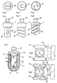
- Figures 1 to 2 represent such a known arrangement.
- a better solution can be achieved by a spiral design of the tubes, as shown in Figures 3 and 4. In this case, longer pipe lengths and thus higher outputs are obtained with the same size.
- Figures 5 and 6 show a further improvement in that the interior of the filament is designed so that at least parts of the ballast can be accommodated in the center of the filament, which either allows a shortened version of the lamp with the same Leisutng, or a higher power with the same overall length .
- the gas discharge vessel of the compact lamp from an outer envelope 2, which corresponds approximately to the outer diameter of the compact lamp, and not, as previously, from a combination of thin tubes, the required electrode connections being arranged in this way are that they can be connected directly to the ballast in a simple manner to form a complete compact lamp, it being essential to the invention that at least one of the electrodes is annular.
- the first of the two required electrodes is arranged on one side of the outer shell 2 and the second electrode 5 on the opposite side of the outer shell, with its connection 6 via a sealed, centrally located inner tube 8 is guided to the outside, preferably in the direction of the connection 4 of the first electrode 3.
- the diameter of the inner tube 8 is advantageously chosen so that there is an optimal distance of a maximum of 12 mm between the inner tube 8 and the outer shell 2.
- this ensures good properties of the gas discharge, but such a dimension also allows parts of the ballast 7 to be accommodated within the inner tube 8 and enables the compact lamp to have more favorable overall lengths.
- the construction according to the invention also has a cost-saving effect, in that only the inside of the outer shell 2 is coated with an expensive fluorescent coating 9.
- the inner tube does not have to be covered with a fluorescent material. Rather, it is recommended to provide the inner tube 8 with a well-reflective coating which increases the intensity of the irradiation of the phosphor coating.
- An inside electrically conductive coating on the inner tube 8 can favor it by its electrostatic influence on the ignition process and represents a further improvement possibility of the invention. Such an invisible application of a coating for ignition aid is not possible with the previous designs.
- the rotationally symmetrical shape of a gas discharge vessel according to the invention favors the arrangement of annular electrodes.
- the electrode 5 or the electrode 10 can advantageously be implemented either as a wire ring, or as a coiled wire ring in the case of heated electrodes, or also as a vapor-deposited conductive layer, which even allows simple heating in a known manner.
- the ring electrode 10 Under certain conditions, with high quality requirements, it is expedient to divide the ring electrode 10 into several segments and to assign terminals 12 to each segment 11.
- Coupling elements 13 include both inductive and ohmic or capacitive connections, which can be produced simply and inexpensively, particularly when the segments 11 are vapor-deposited.
- the special measure according to the invention for homogenization of the discharge consists in providing a type of ionization chamber in the form of a cavity 14 at least on one electrode 5.
- a type of ionization chamber favors the maintenance of the discharge in AC operation, but also a better spatial distribution thereof, so that special shadows are avoided. A particularly good ignition is also achieved.
- heating of the electrodes is also readily possible, provided that the additionally required heating connections are provided.
- additional ignition electrodes are also provided.
- FIG. 5 shows the possible spatial shortening of the overall length of a compact lamp by allowing a part 22 of the ballast 7 to be immersed in the filament.
- FIG. 7 shows an improved example of a gas discharge vessel according to the invention. Here, the volume of the discharge space is reduced by a large radius of the inner tube 8. The distance between the inner tube 8 and outer shell 2 is small. The result is cheaper evacuation and filling with gas.
- the inner tube 8 is provided with a coating 21 which can fulfill several tasks.
- a coating 21 which can fulfill several tasks.
- As an electrically conductive layer it capacitively favors the ignition behavior of the gas discharge.
- As a highly reflective layer it reflects the ultraviolet radiation occurring in the gas discharge space and stimulates the phosphor coating 9 to emit light more intensely. The result is a higher luminous efficacy.
- the annular electrode 10 which is schematically evaporated in FIG. 7 with its connections 12, has a direct connection to the ballast 7, which is also connected to the electrode 5 via the connection 6.
- the schematically shown cavity 14 as a trough in the area of the electrode 5 avoids shadowing and promotes gas discharge. It represents an ionization chamber.
- FIG. 8 shows a schematic circuit diagram of an annular electrode 10 which is divided into several segments 11. Each segment 11 has a connection 12 which is connected to the ballast 7.
- the ballast 7 controls the individual segments cyclically in rapid succession, so that the areas of the gas discharge assigned to the segments 11 are acted upon without flickering.
- FIG. 9 shows another variant of the control of the segments 11.
- the segments 11 are connected via coupling elements 13, so that they can work independently of one another.
- the electrodes 5 or 10 can be heated without further ado. Only additional heating connections are required. Additional ignition electrodes are also possible in a known manner.
Claims (7)
- Lampe compacte comportant une enveloppe extérieure translucide (2) qui présente une bordure en forme de coupole et dont le côté intérieur est revêtu au moins partiellement d'une couche de matière fluorescente (9), un corps intérieur cylindrique qui est placé dans l'enveloppe extérieure (2) symétriquement par rapport à celle-ci et qui forme, avec ladite enveloppe extérieure et un culot (19) obturant l'enveloppe de raccordement, un espace de décharge gazeuse fermé, et des électrodes (5, 10) qui sont disposées dans l'espace de décharge gazeuse, une première électrode (5) étant disposée au niveau du corps intérieur, en face de la bordure en forme de coupole de l'enveloppe extérieure, tandis qu'une seconde électrode (10) est prévue dans l'espace de décharge gazeuse, au niveau du culot, caractérisée en ce que l'une au moins des électrodes (5, 10) a une forme annulaire et est divisée en segments, et des raccordements (12) sont associés à chaque segment (11), étant précisé qu'un espace creux (14) est prévu comme chambre d'ionisation autour de l'une au moins des électrodes (3, 5), et que le corps intérieur comprend un tube intérieur creux (8) dans lequel est placé un ballast (7).
- Lampe compacte selon la revendication 1, caractérisée en ce que les segments (11) sont aptes à être commandés de façon cyclique par le ballast (7) par l'intermédiaire de leurs raccordements (12).
- Lampe compacte selon la revendication 1 ou 2, caractérisée en ce que les segments (11) sont aptes à être commandés tous ensemble ou par groupes par le ballast (7) par l'intermédiaire d'éléments de couplage électriques (13).
- Lampe compacte selon l'une au moins des revendications précédentes, caractérisée en ce que d'autres raccordements de chauffage ou des raccordements de chauffage supplémentaires sont prévus pour chauffer les électrodes (3, 5, 10).
- Lampe compacte selon l'une au moins des revendications précédentes, caractérisée en ce que des électrodes d'amorçage sont prévues pour un meilleur amorçage de la décharge gazeuse.
- Lampe compacte selon la revendication 1, caractérisée en ce que l'écartement de paroi entre l'enveloppe extérieure (2) et le tube intérieur (8) est de 12 mm maximum.
- Lampe compacte selon la revendication 1, caractérisée en ce que le tube intérieur (8) est pourvu au moins en partie d'une couche (21) conductrice et/ou réfléchissante.
Applications Claiming Priority (2)
| Application Number | Priority Date | Filing Date | Title |
|---|---|---|---|
| DE4027783A DE4027783A1 (de) | 1990-09-03 | 1990-09-03 | Gasentladungsgeraet fuer kompaktlampen |
| DE4027783 | 1991-09-03 |
Publications (2)
| Publication Number | Publication Date |
|---|---|
| EP0474065A1 EP0474065A1 (fr) | 1992-03-11 |
| EP0474065B1 true EP0474065B1 (fr) | 1995-06-14 |
Family
ID=6413420
Family Applications (1)
| Application Number | Title | Priority Date | Filing Date |
|---|---|---|---|
| EP91114160A Expired - Lifetime EP0474065B1 (fr) | 1990-09-03 | 1991-08-23 | Récipient pour lampes à décharge compactes |
Country Status (7)
| Country | Link |
|---|---|
| US (1) | US5243256A (fr) |
| EP (1) | EP0474065B1 (fr) |
| JP (1) | JPH0789477B2 (fr) |
| CN (1) | CN1032396C (fr) |
| AT (1) | ATE123905T1 (fr) |
| CA (1) | CA2050372A1 (fr) |
| DE (2) | DE4027783A1 (fr) |
Families Citing this family (22)
| Publication number | Priority date | Publication date | Assignee | Title |
|---|---|---|---|---|
| DE4241314A1 (de) * | 1992-12-08 | 1994-06-09 | Holzer Walter | Kompaktlampe mit Adapter |
| WO1994029895A1 (fr) * | 1993-02-24 | 1994-12-22 | Lee, Ok, Yun | Tube de type en double spirale pour lampe fluorescente, et lampe fluorescente du type ampoule comprenant un tel tube demontable |
| DE4439727A1 (de) * | 1994-11-09 | 1996-05-15 | Walter Holzer | Sockel für Kompaktlampen |
| US5705883A (en) * | 1995-03-31 | 1998-01-06 | General Electric Company | Reduced length compact fluorescent lamp and method of forming same |
| EP0735569B1 (fr) * | 1995-03-31 | 2003-09-24 | General Electric Company | Lampe fluorescente |
| DE19519518A1 (de) * | 1995-06-01 | 1996-12-05 | Walter Holzer | Gasentladungsgefäß für Niederdruckentladungslampen |
| DE19534245A1 (de) * | 1995-09-18 | 1997-03-20 | Holzer Walter Prof Dr H C Ing | Einseitig gesockelte Kompaktleuchtstofflampe mit trennbarem Vorschaltgerät |
| JPH09185951A (ja) * | 1995-09-29 | 1997-07-15 | Toshiba Lighting & Technol Corp | 蛍光ランプ装置および照明器具 |
| DE19607208C2 (de) * | 1996-02-26 | 2002-02-21 | Walter Holzer | Leuchtstofflampe mit auswechselbarem Leuchtteil |
| EP0926705A1 (fr) * | 1997-12-23 | 1999-06-30 | Patent-Treuhand-Gesellschaft für elektrische Glühlampen mbH | Radiateur plat à densité lumineuse de surface modulée localement |
| DE19755680A1 (de) * | 1997-12-15 | 1999-06-17 | Holzer Walter Prof Dr H C Ing | Einseitig gesockeltes Gasentladungsgefäß für Energiesparlampen |
| KR20000024183A (ko) * | 2000-01-27 | 2000-05-06 | 최근대 | 이중나선 벌브형 전구식 형광등 |
| JP4820051B2 (ja) * | 2002-06-12 | 2011-11-24 | パナソニック株式会社 | 発光管、発光管の製造方法及び低圧水銀ランプ |
| KR100492938B1 (ko) * | 2002-09-11 | 2005-05-30 | 강성진 | 컴팩트형 방전 램프 |
| US20050088076A1 (en) * | 2003-10-27 | 2005-04-28 | Chi-Jung Chu | Fluorescent lamp |
| DE102004018104A1 (de) * | 2004-04-14 | 2005-11-10 | Patent-Treuhand-Gesellschaft für elektrische Glühlampen mbH | Gasentladungslampe mit Helixform des Entladungsrohres und innerem Rohrstück |
| PL1941535T3 (pl) * | 2005-10-26 | 2010-08-31 | Skirtlight S A | Kompaktowa lampa fluorescencyjna |
| DE102007046343A1 (de) * | 2007-09-27 | 2009-04-02 | Osram Gesellschaft mit beschränkter Haftung | Verfahren zum Verbinden eines Entladungsgefäßes einer Entladungslampe mit einem Rohrstück, insbesondere einem Pumprohr |
| US8446085B2 (en) | 2011-09-23 | 2013-05-21 | General Electric Company | Fluorescent lamp with zinc silicate phosphor and protective phosphor layer |
| US8415869B1 (en) | 2011-09-23 | 2013-04-09 | General Electric Company | Fluorescent lamp with underlying yttrium vanadate phosphor layer and protective phosphor layer |
| US20130193835A1 (en) | 2012-01-30 | 2013-08-01 | General Electric Company | Fluorescent lamp with coated phosphor particles |
| US8987984B2 (en) | 2012-10-19 | 2015-03-24 | General Electric Company | Fluorescent lamp including phosphor composition with special BAMn phosphor, (Ba,Sr,Ca)(Mg1-x Mnx)Al10O17:Eu2+ |
Family Cites Families (20)
| Publication number | Priority date | Publication date | Assignee | Title |
|---|---|---|---|---|
| US1188194A (en) * | 1914-05-07 | 1916-06-20 | Gen Electric | Gaseous-conductor lamp. |
| DE833084C (de) * | 1951-06-05 | 1952-03-03 | Lumalampan Ab | Elektrische Entladungsroehre mit Leuchtstoffbelag |
| DE968549C (de) * | 1952-09-15 | 1958-03-06 | Ing Karl Nowak | Gasentladungslampe mit einem sich nahezu ueber die Lampenlaenge erstreckenden Einbaukolben |
| DE1589413B2 (de) * | 1967-08-22 | 1971-05-19 | Walz, Alfred, Prof Dr Ing , 7830 Emmendingen | Gasentladungslampe |
| US3609436A (en) * | 1969-04-21 | 1971-09-28 | Gen Electric | Fluorescent light source with a plurality of sequentially energized electrodes |
| DE2125638A1 (de) * | 1971-05-24 | 1972-12-07 | Doehner G | Fluoreszierender Beleuchtungskörper |
| NL7812539A (nl) * | 1978-02-14 | 1979-08-16 | Philips Nv | Lagedrukkwikdampontladingslamp. |
| US4281271A (en) * | 1979-06-12 | 1981-07-28 | Westinghouse Electric Corp. | Compact fluorescent lamp having a partitioned envelope |
| NL7906202A (nl) * | 1979-08-15 | 1981-02-17 | Philips Nv | Lagedrukontladingslamp. |
| US4341977A (en) * | 1980-02-04 | 1982-07-27 | Leo Gross | Arc spreading with initiators |
| US4347460A (en) * | 1980-03-03 | 1982-08-31 | Gte Products Corporation | Compact fluorescent lamp assembly |
| NL8001280A (nl) * | 1980-03-04 | 1981-10-01 | Philips Nv | Lagedrukontladingslamp. |
| NL8005112A (nl) * | 1980-09-11 | 1982-04-01 | Philips Nv | Lagedrukkwikdampontladingslamp. |
| DE3307763A1 (de) * | 1983-03-04 | 1984-09-06 | Patent-Treuhand-Gesellschaft für elektrische Glühlampen mbH, 8000 München | Einseitig gesockelte niederdruckentladungslampe |
| DE3333643A1 (de) * | 1983-09-17 | 1985-04-11 | Wilhelm Dr.-Ing. 5340 Bad Honnef Lepper | Leuchtstofflampe |
| DE3337441A1 (de) * | 1983-10-14 | 1985-04-25 | Bernhard Dipl.-Wirtsch.-Ing. 3002 Wedemark Mittelhäuser | Innenrueckblickspiegel fuer kraftfahrzeuge |
| DE3741566C2 (de) * | 1987-12-08 | 1996-07-18 | Patent Treuhand Ges Fuer Elektrische Gluehlampen Mbh | Kompakte Niederdruckentladungslampe |
| US4587462A (en) * | 1984-08-10 | 1986-05-06 | Gte Laboratories Incorporated | Fluorescent light source with parallel DC discharges |
| KR900008228B1 (ko) * | 1986-10-31 | 1990-11-06 | 가부시기가이샤 도시바 | 다색광을 출력하는 형광등 |
| US4935664A (en) * | 1988-09-20 | 1990-06-19 | Gte Products Corporation | Diffuse discharge lamp |
-
1990
- 1990-09-03 DE DE4027783A patent/DE4027783A1/de not_active Withdrawn
-
1991
- 1991-08-23 DE DE59105694T patent/DE59105694D1/de not_active Expired - Fee Related
- 1991-08-23 EP EP91114160A patent/EP0474065B1/fr not_active Expired - Lifetime
- 1991-08-23 AT AT91114160T patent/ATE123905T1/de not_active IP Right Cessation
- 1991-08-30 CA CA002050372A patent/CA2050372A1/fr not_active Abandoned
- 1991-09-02 JP JP3250390A patent/JPH0789477B2/ja not_active Expired - Lifetime
- 1991-09-03 US US07/754,076 patent/US5243256A/en not_active Expired - Fee Related
- 1991-09-03 CN CN91109294A patent/CN1032396C/zh not_active Expired - Fee Related
Also Published As
| Publication number | Publication date |
|---|---|
| EP0474065A1 (fr) | 1992-03-11 |
| CN1032396C (zh) | 1996-07-24 |
| ATE123905T1 (de) | 1995-06-15 |
| CA2050372A1 (fr) | 1992-03-04 |
| JPH05121045A (ja) | 1993-05-18 |
| DE4027783A1 (de) | 1992-04-30 |
| JPH0789477B2 (ja) | 1995-09-27 |
| US5243256A (en) | 1993-09-07 |
| CN1063179A (zh) | 1992-07-29 |
| DE59105694D1 (de) | 1995-07-20 |
Similar Documents
| Publication | Publication Date | Title |
|---|---|---|
| EP0474065B1 (fr) | Récipient pour lampes à décharge compactes | |
| DE3005017C2 (fr) | ||
| DE69820992T2 (de) | Hochdruckentladungslampe | |
| DE2835574C2 (fr) | ||
| DE2835183A1 (de) | Lampeneinheit | |
| DE602004010629T2 (de) | Gasentladungslampe | |
| EP0237647A1 (fr) | Lampe à décharge pour véhicule | |
| EP1276137B1 (fr) | Lampe a décharge à barrière diélectrique avec une aide à l'allumage | |
| EP0393449B1 (fr) | Lampe fluorescente | |
| DE2118828B2 (de) | Hochdruck-Natriumdampf-Entladungslampe | |
| DE1065092B (de) | Blitzlichtentladungslampe | |
| DE602004008259T2 (de) | Gasentladungslampe | |
| EP0040812A1 (fr) | Lampe à décharge à basse pression | |
| DE1489407B2 (de) | Elektrische gasgefuellte jodgluehlampe1 | |
| EP0118834B1 (fr) | Lampe à décharge à basse pression avec culot à un côté et procédé de fabrication | |
| DD284103A5 (de) | Elektrische lampe | |
| DE3307763A1 (de) | Einseitig gesockelte niederdruckentladungslampe | |
| DE3519627A1 (de) | Hochdruckentladungslampe zur verwendung in kraftfahrzeugscheinwerfern | |
| DE102004043636A1 (de) | Hochdruckentladungslampe | |
| DE2535922A1 (de) | Quecksilberdampf-hochdruckentladungslampe fuer horizontale brennlage | |
| EP0908667A2 (fr) | Lampe électrique | |
| DE102009006438B3 (de) | Leuchte mit einer Gasentladungslampe | |
| DE19519518A1 (de) | Gasentladungsgefäß für Niederdruckentladungslampen | |
| DE102021206702A1 (de) | Hochdruckentladungslampe, insbesondere natriumdampf-hochdrucklampe, mit verbesserter zündfähigkeit | |
| DE19517993A1 (de) | Gasentladungslampe mit Adapter |
Legal Events
| Date | Code | Title | Description |
|---|---|---|---|
| PUAI | Public reference made under article 153(3) epc to a published international application that has entered the european phase |
Free format text: ORIGINAL CODE: 0009012 |
|
| AK | Designated contracting states |
Kind code of ref document: A1 Designated state(s): AT BE CH DE DK ES FR GB GR IT LI LU NL SE |
|
| 17P | Request for examination filed |
Effective date: 19920820 |
|
| 17Q | First examination report despatched |
Effective date: 19930624 |
|
| GRAA | (expected) grant |
Free format text: ORIGINAL CODE: 0009210 |
|
| AK | Designated contracting states |
Kind code of ref document: B1 Designated state(s): AT BE CH DE DK ES FR GB GR IT LI LU NL SE |
|
| PG25 | Lapsed in a contracting state [announced via postgrant information from national office to epo] |
Ref country code: IT Free format text: LAPSE BECAUSE OF FAILURE TO SUBMIT A TRANSLATION OF THE DESCRIPTION OR TO PAY THE FEE WITHIN THE PRE;WARNING: LAPSES OF ITALIAN PATENTS WITH EFFECTIVE DATE BEFORE 2007 MAY HAVE OCCURRED AT ANY TIME BEFORE 2007. THE CORRECT EFFECTIVE DATE MAY BE DIFFERENT FROM THE ONE RECORDED.SCRIBED TIME-LIMIT Effective date: 19950614 Ref country code: BE Effective date: 19950614 Ref country code: GR Free format text: LAPSE BECAUSE OF FAILURE TO SUBMIT A TRANSLATION OF THE DESCRIPTION OR TO PAY THE FEE WITHIN THE PRESCRIBED TIME-LIMIT Effective date: 19950614 Ref country code: GB Effective date: 19950614 Ref country code: NL Free format text: LAPSE BECAUSE OF NON-PAYMENT OF DUE FEES Effective date: 19950614 Ref country code: ES Free format text: THE PATENT HAS BEEN ANNULLED BY A DECISION OF A NATIONAL AUTHORITY Effective date: 19950614 Ref country code: FR Effective date: 19950614 Ref country code: DK Effective date: 19950614 |
|
| REF | Corresponds to: |
Ref document number: 123905 Country of ref document: AT Date of ref document: 19950615 Kind code of ref document: T |
|
| REF | Corresponds to: |
Ref document number: 59105694 Country of ref document: DE Date of ref document: 19950720 |
|
| PG25 | Lapsed in a contracting state [announced via postgrant information from national office to epo] |
Ref country code: AT Effective date: 19950823 |
|
| PG25 | Lapsed in a contracting state [announced via postgrant information from national office to epo] |
Ref country code: LU Free format text: LAPSE BECAUSE OF NON-PAYMENT OF DUE FEES Effective date: 19950831 Ref country code: LI Effective date: 19950831 Ref country code: CH Effective date: 19950831 |
|
| PG25 | Lapsed in a contracting state [announced via postgrant information from national office to epo] |
Ref country code: SE Effective date: 19950914 |
|
| EN | Fr: translation not filed | ||
| GBV | Gb: ep patent (uk) treated as always having been void in accordance with gb section 77(7)/1977 [no translation filed] |
Effective date: 19950614 |
|
| NLV1 | Nl: lapsed or annulled due to failure to fulfill the requirements of art. 29p and 29m of the patents act | ||
| REG | Reference to a national code |
Ref country code: CH Ref legal event code: PL |
|
| PLBE | No opposition filed within time limit |
Free format text: ORIGINAL CODE: 0009261 |
|
| STAA | Information on the status of an ep patent application or granted ep patent |
Free format text: STATUS: NO OPPOSITION FILED WITHIN TIME LIMIT |
|
| 26N | No opposition filed | ||
| PGFP | Annual fee paid to national office [announced via postgrant information from national office to epo] |
Ref country code: DE Payment date: 19960919 Year of fee payment: 6 |
|
| PG25 | Lapsed in a contracting state [announced via postgrant information from national office to epo] |
Ref country code: DE Free format text: LAPSE BECAUSE OF NON-PAYMENT OF DUE FEES Effective date: 19980501 |