EP0474065B1 - Vessel for compact discharge tubes - Google Patents
Vessel for compact discharge tubes Download PDFInfo
- Publication number
- EP0474065B1 EP0474065B1 EP91114160A EP91114160A EP0474065B1 EP 0474065 B1 EP0474065 B1 EP 0474065B1 EP 91114160 A EP91114160 A EP 91114160A EP 91114160 A EP91114160 A EP 91114160A EP 0474065 B1 EP0474065 B1 EP 0474065B1
- Authority
- EP
- European Patent Office
- Prior art keywords
- electrodes
- compact lamp
- compact
- lamp according
- gas discharge
- Prior art date
- Legal status (The legal status is an assumption and is not a legal conclusion. Google has not performed a legal analysis and makes no representation as to the accuracy of the status listed.)
- Expired - Lifetime
Links
Images
Classifications
-
- H—ELECTRICITY
- H01—ELECTRIC ELEMENTS
- H01J—ELECTRIC DISCHARGE TUBES OR DISCHARGE LAMPS
- H01J61/00—Gas-discharge or vapour-discharge lamps
- H01J61/02—Details
- H01J61/56—One or more circuit elements structurally associated with the lamp
-
- H—ELECTRICITY
- H01—ELECTRIC ELEMENTS
- H01J—ELECTRIC DISCHARGE TUBES OR DISCHARGE LAMPS
- H01J61/00—Gas-discharge or vapour-discharge lamps
- H01J61/70—Lamps with low-pressure unconstricted discharge having a cold pressure < 400 Torr
Definitions
- Compact lamps also called energy-saving lamps, have been in high demand in recent years due to their low power consumption of only about a fifth compared to conventional incandescent lamps.
- a compact lamp is already known, with an outer envelope which has a dome-shaped end and with a solid body protruding symmetrically into the outer envelope.
- a gas discharge space is formed by the outer shell, the solid body and a connection base connecting the outer shell and the solid body.
- an electrode is formed on the end of the solid body of the electrodes opposite the dome part of the outer envelope and, on the opposite side on the dome of the lamp in the interior of the discharge space, a single ignition electrode which, like the other electrodes, has a spiral configuration.
- the disadvantage is that the lamp described here is not very compact because the ballast is only in the base.
- a compact lamp is known from US Pat. No. 4,571,526, in which the gas discharge space is likewise formed by an outer envelope and an inner tube projecting into it. The ballast is inserted into the hollow inner tube.
- the object of the invention is to achieve the largest possible luminous area with a compact structure, with good ignition and economical effort.
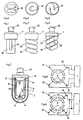
- Figures 1 to 2 represent such a known arrangement.
- a better solution can be achieved by a spiral design of the tubes, as shown in Figures 3 and 4. In this case, longer pipe lengths and thus higher outputs are obtained with the same size.
- Figures 5 and 6 show a further improvement in that the interior of the filament is designed so that at least parts of the ballast can be accommodated in the center of the filament, which either allows a shortened version of the lamp with the same Leisutng, or a higher power with the same overall length .
- the gas discharge vessel of the compact lamp from an outer envelope 2, which corresponds approximately to the outer diameter of the compact lamp, and not, as previously, from a combination of thin tubes, the required electrode connections being arranged in this way are that they can be connected directly to the ballast in a simple manner to form a complete compact lamp, it being essential to the invention that at least one of the electrodes is annular.
- the first of the two required electrodes is arranged on one side of the outer shell 2 and the second electrode 5 on the opposite side of the outer shell, with its connection 6 via a sealed, centrally located inner tube 8 is guided to the outside, preferably in the direction of the connection 4 of the first electrode 3.
- the diameter of the inner tube 8 is advantageously chosen so that there is an optimal distance of a maximum of 12 mm between the inner tube 8 and the outer shell 2.
- this ensures good properties of the gas discharge, but such a dimension also allows parts of the ballast 7 to be accommodated within the inner tube 8 and enables the compact lamp to have more favorable overall lengths.
- the construction according to the invention also has a cost-saving effect, in that only the inside of the outer shell 2 is coated with an expensive fluorescent coating 9.
- the inner tube does not have to be covered with a fluorescent material. Rather, it is recommended to provide the inner tube 8 with a well-reflective coating which increases the intensity of the irradiation of the phosphor coating.
- An inside electrically conductive coating on the inner tube 8 can favor it by its electrostatic influence on the ignition process and represents a further improvement possibility of the invention. Such an invisible application of a coating for ignition aid is not possible with the previous designs.
- the rotationally symmetrical shape of a gas discharge vessel according to the invention favors the arrangement of annular electrodes.
- the electrode 5 or the electrode 10 can advantageously be implemented either as a wire ring, or as a coiled wire ring in the case of heated electrodes, or also as a vapor-deposited conductive layer, which even allows simple heating in a known manner.
- the ring electrode 10 Under certain conditions, with high quality requirements, it is expedient to divide the ring electrode 10 into several segments and to assign terminals 12 to each segment 11.
- Coupling elements 13 include both inductive and ohmic or capacitive connections, which can be produced simply and inexpensively, particularly when the segments 11 are vapor-deposited.
- the special measure according to the invention for homogenization of the discharge consists in providing a type of ionization chamber in the form of a cavity 14 at least on one electrode 5.
- a type of ionization chamber favors the maintenance of the discharge in AC operation, but also a better spatial distribution thereof, so that special shadows are avoided. A particularly good ignition is also achieved.
- heating of the electrodes is also readily possible, provided that the additionally required heating connections are provided.
- additional ignition electrodes are also provided.
- FIG. 5 shows the possible spatial shortening of the overall length of a compact lamp by allowing a part 22 of the ballast 7 to be immersed in the filament.
- FIG. 7 shows an improved example of a gas discharge vessel according to the invention. Here, the volume of the discharge space is reduced by a large radius of the inner tube 8. The distance between the inner tube 8 and outer shell 2 is small. The result is cheaper evacuation and filling with gas.
- the inner tube 8 is provided with a coating 21 which can fulfill several tasks.
- a coating 21 which can fulfill several tasks.
- As an electrically conductive layer it capacitively favors the ignition behavior of the gas discharge.
- As a highly reflective layer it reflects the ultraviolet radiation occurring in the gas discharge space and stimulates the phosphor coating 9 to emit light more intensely. The result is a higher luminous efficacy.
- the annular electrode 10 which is schematically evaporated in FIG. 7 with its connections 12, has a direct connection to the ballast 7, which is also connected to the electrode 5 via the connection 6.
- the schematically shown cavity 14 as a trough in the area of the electrode 5 avoids shadowing and promotes gas discharge. It represents an ionization chamber.
- FIG. 8 shows a schematic circuit diagram of an annular electrode 10 which is divided into several segments 11. Each segment 11 has a connection 12 which is connected to the ballast 7.
- the ballast 7 controls the individual segments cyclically in rapid succession, so that the areas of the gas discharge assigned to the segments 11 are acted upon without flickering.
- FIG. 9 shows another variant of the control of the segments 11.
- the segments 11 are connected via coupling elements 13, so that they can work independently of one another.
- the electrodes 5 or 10 can be heated without further ado. Only additional heating connections are required. Additional ignition electrodes are also possible in a known manner.
Abstract
Description
Kompaktlampen, auch Sparlampen genannt, sind in den letzten Jahren aufgrund ihres geringen Stromverbrauchs von nur etwa einem Fünftel im Vergleich zu herkömmlichen Glühlampen stark gefragt.Compact lamps, also called energy-saving lamps, have been in high demand in recent years due to their low power consumption of only about a fifth compared to conventional incandescent lamps.
Aus der DE-A-33 33 643 ist bereits eine Kompaktlampe bekannt, mit einer Außenhülle, die einen kuppelförmigen Abschluß hat und mit einem symmetrisch in die Außenhülle hineinragenden Massivkörper. Dabei wird durch die Außenhülle, den Massivkörper und einen die Außenhülle und den Massivkörper verbindenden Anschlußsockel ein Gasentladungsraum gebildet.From DE-A-33 33 643 a compact lamp is already known, with an outer envelope which has a dome-shaped end and with a solid body protruding symmetrically into the outer envelope. In this case, a gas discharge space is formed by the outer shell, the solid body and a connection base connecting the outer shell and the solid body.
Bei der bekannten Lampe ist eine Elektrode an dem dem Kuppelteil der Außenhülle gegenüberliegenden Ende des Massivkörpers der Elektroden ausgebildet sowie gegenüberliegend an der Kuppel der Lampe im Innern des Entladungsraumes eine einzelne Zündelektrode, die ebenso wie die anderen Elektroden spiralig ausgebildet ist. Nachteilig ist, daß die hier beschriebene Lampe nicht sehr kompakt ausgebildet ist, da sich das Vorschaltgerät ausschließlich im Sockel befindet.In the known lamp, an electrode is formed on the end of the solid body of the electrodes opposite the dome part of the outer envelope and, on the opposite side on the dome of the lamp in the interior of the discharge space, a single ignition electrode which, like the other electrodes, has a spiral configuration. The disadvantage is that the lamp described here is not very compact because the ballast is only in the base.
Aus der Druckschrift US-A-4,571,526 ist eine Kompaktlampe bekannt, bei der ebenfalls der Gasentladungsraum durch eine Außenhülle und ein in diese hineinragendes Innenrohr gebildet wird. Das Vorschaltgerät ist dabei in das hohle Innenrohr eingesetzt.A compact lamp is known from US Pat. No. 4,571,526, in which the gas discharge space is likewise formed by an outer envelope and an inner tube projecting into it. The ballast is inserted into the hollow inner tube.
Aufgabe der Erfindung ist, eine möglichst große Leuchtfläche bei gedrängtem Aufbau, bei guter Zündung und sparsamem Aufwand zu erzielen.The object of the invention is to achieve the largest possible luminous area with a compact structure, with good ignition and economical effort.
Diese Aufgabe wird durch eine Kompaktlampe gemäß dem Anspruch 1 gelöst.This object is achieved by a compact lamp according to claim 1.
Herkömmliche Kompaktlampen benützen vielfach dünne Rohre von etwa 10 bis 12 mm Durchmesser, welche als mehrere parallel angeordnete, aber in Serie geschaltete Stäbe verbunden werden.Conventional compact lamps often use thin tubes of approximately 10 to 12 mm in diameter, which are connected as several rods arranged in parallel but connected in series.
Figur 1 bis 2 stellen eine solche bekannte Anordnung dar. Eine bessere Lösung kann man durch eine gewendelte Ausführung der Rohre erreichen, wie sie in Figur 3 und 4 dargestellt ist. Hier ergeben sich bereits bei gleicher Baugröße größere Rohrlängen und damit höhere Leistungen.Figures 1 to 2 represent such a known arrangement. A better solution can be achieved by a spiral design of the tubes, as shown in Figures 3 and 4. In this case, longer pipe lengths and thus higher outputs are obtained with the same size.
Figur 5 und 6 zeigen eine weitere Verbesserung, indem der Innenraum der Wendel so gestaltet ist, daß zumindest Teile des Vorschaltgeräts im Zentrum der Leuchtwendel untergebracht werden können, was entweder eine verkürzte Ausführung der Lampe bei gleicher Leisutng, oder eine höhere Leistung bei gleicher Baulänge gestattet.Figures 5 and 6 show a further improvement in that the interior of the filament is designed so that at least parts of the ballast can be accommodated in the center of the filament, which either allows a shortened version of the lamp with the same Leisutng, or a higher power with the same overall length .
Allen beschriebenen Ausführungen haftet jedoch der gemeinsame Nachteil an, daß zwischen den Rohren nichtleuchtende Zonen bestehen, und die Rohre sich gegenseitig überdecken und sich dadurch abschatten.However, all the designs described have the common disadvantage that there are non-luminous zones between the tubes, and the tubes overlap one another and thereby shade themselves.
Um die angeführten Nachteile zu vermeiden, wird erfindungsgemäss vorgeschlagen, das Gasentladungsgefäss der Kompaktlampe aus einer Außenhülle 2, welche etwa dem Außendurchmesser der Kompaktlampe entspricht, aufzubauen und nicht, wie bisher, aus einer Kombination von dünnen Rohren, wobei die erforderlichen Elektrodenanschlüsse derart angeorndet sind, daß sie direkt mit dem Vorschaltgerät in einfacher Weise zu einer kompleten Kompaktlampe verbunden werden können, wobei es erfindungswesentlich ist,daß zumindest eine der Elektroden ringförmig ausgebildet ist.In order to avoid the disadvantages mentioned, it is proposed according to the invention to construct the gas discharge vessel of the compact lamp from an
Damit erzielt man eine besonders gute Zündung und eine geschlossene Leuchtfläche. Bei guter Ausnutzung der Oberfläche werden auch besondere Abschattungen vermieden. Die sonst vorhandenen Zwischenräume entfallen und die geschlossene Außenhülle kann einfach gereinigt werden, was bei vielen bisherigen Kompaktlampen vielfach unmöglich ist und zu baldigen Lichteinbußen führte.This gives a particularly good ignition and a closed illuminated area. With good use of the surface, special shadows are also avoided. The otherwise existing gaps are eliminated and the closed outer envelope can be easily cleaned, which is often impossible with many previous compact lamps and led to a loss of light soon.
Um die Gasentladung und ihre gleichmässige Verteilung optimal zu gestalten, wird in einer ersten Ausführungsform (Figur 7) die erste der beiden erforderlichen Elektroden auf einer Seite der Außenhülle 2 angeordnet und die zweite Elektrode 5 auf der gegenüberleigenden Seite der Außenhülle, wobei deren Anschluß 6 über ein abgedichtetes, möglichst zentral gelegenes Innenrohr 8 nach außen geführt wird, vorzugsweise in Richtung des Anschlußes 4 der ersten Elektrode 3.In order to optimally design the gas discharge and its uniform distribution, in a first embodiment (FIG. 7) the first of the two required electrodes is arranged on one side of the
In einer weiteren Ausführungsform nach Figur 9 wird der Durchmesser des Innenrohres 8 vorteilhaft so gewählt, daß sich zwischen Innenrohr 8 und Außenhülle 2 ein optimaler Abstand von maximal 12 mm ergibt. Das sichert erfahrungsgemäss gute Eigenschaften der Gasentladung, aber eine solche Dimension gestattet auch die Unterbringung von Teilen des Vorschaltgerätes 7 innerhalb des Innenrohres 8 und ermöglicht günstigere Baulängen der Kompaktlampe.In a further embodiment according to FIG. 9, the diameter of the
Kostensparend wirkt sich auch die erfindungsgemässe Konstruktion aus, nur die Innenseite der Außenhülle 2 mit einem teuren Leuchtstoffbelag 9 zu beschichten. Das Innenrohr muß nicht mit einem Leuchstoffbelag versehen werden. Es wird vielmehr empfohlen, das Innenrohr 8 mit einem gut reflektierenden Belag zu versehen, welcher die Intensität der Bestrahlung des Leuchtstoffbelages erhöht.The construction according to the invention also has a cost-saving effect, in that only the inside of the
Ein innenseitiger elektrisch leitender Belag am Innenrohr 8 kann durch seinen elektrostatischen Einfluß auf den Zündvorgang diesen begünstigen und stellt eine weitere Verbesserungsmöglichkeit der Erfindung dar. Eine derartige unsichtbare Anbringung eines Belages zur Zündhilfe ist bei den bisherigen Konstruktionen nicht möglich.An inside electrically conductive coating on the
Die rotationssymmetrische Form eines erfindungsgemässen Gasentladungsgefässes begünstigt die Anordnung von ringförmigen Elektroden. Besonders die Elektrode 5 oder die Elektrode 10 lässt sich vorteilhaft entweder als Drahtring, oder als gewendelter Drahtring bei beheizten Elektroden, oder auch als aufgedampfte leitende Schicht ausführen, welche sogar eine einfache Beheizung in bekannter Art gestattet.The rotationally symmetrical shape of a gas discharge vessel according to the invention favors the arrangement of annular electrodes. In particular, the
Unter bestimmten Voraussetzungen, bei hohen Qualitätsanforderungen ist es zweckmässig, die Ringelektrode 10 in mehrere Segmente aufzuteilen und jedem Segment 11 Anschlüsse 12 zuzuordnen.Under certain conditions, with high quality requirements, it is expedient to divide the
Diese Segmente können entweder von dem Vorschaltgerät zyklisch in schneller Form angesteuert werden, oder sie können gemeinsam oder in Gruppen über elektrische Kopplungselemente 13 geschaltet werden. Als Kopplungselemente 13 kommen sowohl induktive als auch ohmsche oder kapazitive Verbindungen in Frage, welche sich besonders bei einem Aufdampfen der Segmente 11 einfachst und kostengünstig herstellen lassen.These segments can either be controlled cyclically in rapid form by the ballast, or they can be switched together or in groups via
Die besondere erfindungsgemässe Maßnahme zur Homogenisierung der Entladung besteht darin, zumindest an einer Elektrode 5 eine Art Ionisierungskammer in Form eines Hohlraumes 14 vorzusehen. Eine solche Ionisierungskammer begünstigt bei Wechselstrombetrieb die Aufrechterhaltung der Entladung, aber auch eine bessere räumliche Verteilung derselben, so daß besondere Abschattungen vermieden werden. Außerdem wird eine besonders gute Zündung erreicht.The special measure according to the invention for homogenization of the discharge consists in providing a type of ionization chamber in the form of a
Auch die Beheizung der Elektroden ist erfindungsgemäss ohne weiteres möglich, sofern man die zusätzlich erforderlichen Heizanschlüsse vorsieht. Das gleiche gilt für zusätzliche Zündelektroden.According to the invention, heating of the electrodes is also readily possible, provided that the additionally required heating connections are provided. The same applies to additional ignition electrodes.
Die nachfolgende Beschreibung von Ausführungsbeispielen ist in keiner Weise als umfassend oder beschränkend aufzufassen, sondern dient lediglich zur besseren Darstellung des Erfindungsgedankens.The following description of exemplary embodiments is in no way to be taken as comprehensive or restrictive, but merely serves to better illustrate the inventive concept.
Die Fig. 1 bis 6 zeigen bisherige Ausführungsformen von Kompaktlampen, die meist mit Leuchtrohren 18 in Stab- oder Wendelform ausgeführt wurden. Die lichttechnisch nicht genutzten Zwischenräume 22 sind klar erkennbar, ebenso die gegenseitige Abschattung der sich überdeckenden Leuchtröhren 18. Im weiteren können auch lichttechnische Abschattungen im Brennbereich auftreten, was an der Außenseite von Kompaktlampen oftmals erkennbar ist.
Bei der erfindungsgemässen Lampe werden Abschattungen des Brennbereichs weitgehend vermieden, insbesonere an der Kuppel der Lampe, weil schon von Anfang an eine gute Zündung mit leitender Ausbreitung von Ionen erfolgt.1 to 6 show previous embodiments of compact lamps, which were mostly carried out with
In the lamp according to the invention, shadowing of the burning area is largely avoided, in particular at the dome of the lamp, because good ignition with conductive propagation of ions takes place right from the start.
Die Ausführung Fig. 5 zeigt die mögliche räumliche Verkürzung der Baulänge einer Kompaktlampe, indem man einen Teil 22 des Vorschaltgeräts 7 in die Wendel eintauchen lässt. Figur 7 zeigt ein verbessertes Beispiel eines erfindungsgemässen Gasentladungsgefässes. Hierbei ist das Volumen des Entladungsraumes durch einen großen Radius des Innenrohres 8 verringert. Der Abstand zwischen Innenrohr 8 und Außenhülle 2 ist klein. Billigeres Evakuieren und Füllen mit Gas ist die Folge.5 shows the possible spatial shortening of the overall length of a compact lamp by allowing a
Das Innenrohr 8 ist nach Figur 7, wo die Erfindung dargestellt ist, mit einer Beschichtung 21 versehen, die mehrere Aufgaben erfüllen kann. Als elektrisch leitende Schicht begünstigt sie kapazitiv das Zündverhalten der Gasentladung. Als gut reflektierende Schicht reflektiert sie die im Gasentladungsraum auftretende Ultraviolettstrahlung und regt den Leuchtstoffbelag 9 zur intensiveren Lichtabgabe an. Eine höhere Lichtausbeute ist die Folge.According to FIG. 7, where the invention is shown, the
Da nur die Außenhülle 2 einen Leuchtstoffbelag 9 besitzt, werden nur tatsächlich Licht aussendende Flächen beschichtet und bisher abgedeckte oder abgeschattete Teilflächen nicht unnötig mit den sehr teuren Leuchtstoffen belebt. Eine weitere Kostensenkung ist die Folge.Since only the
Die in Figur 7 schematisch als aufgedampfte, ringförmige Elektrode 10 mit ihren Anschlüssen 12 hat direkte Verbindung zum Vorschaltgerät 7, welches auch über den Anschluß 6 mit der Elektrode 5 in Verbindung steht.The
Der schematisch dargestellte Hohlraum 14 als Mulde im Bereich der Elektrode 5 vermeidet Abschattungen und begünstigt die Gasentladung. Er stellt eine Ionisierungskammer dar.The schematically shown
In Figur 7 ist zu erkennen, daß infolge der an sich bekannten Unterbringung von Teilen des Vorschaltgeräts 7 im Innenrohr 8 die gesamte Baulänge der Kompaktlampe 1 verkleinert ist, wobei der Zugang zur Einschraubfassung besonders gut gewährleistet ist.In Figure 7 it can be seen that due to the known accommodation of parts of the
Figur 8 zeigt ein schematisches Schaltbild einer ringförmigen Elektrode 10, welche in mehrere Segmente 11 unterteilt ist. Jedes Segment 11 hat einen Anschluß 12, welcher mit dem Vorschaltgerät 7 in Verbindung steht. Das Vorschaltgerät 7 steuert die einzelnen Segmente in schneller Folge zyklisch an, so daß die den Segmenten 11 zugeordneten Bereiche der Gasentladung flimmerfrei beaufschlagt werden.FIG. 8 shows a schematic circuit diagram of an
Figur 9 zeigt eine andere Variante der Ansteuerung der Segmente 11. In diesem Beispiel sind die Segmente 11 über Kopplungselemente 13 verbunden, so daß sie unabhängig voneinander arbeiten können.FIG. 9 shows another variant of the control of the
Die Beheizung der Elektroden 5 oder 10 ist ohne weiteres möglich. Es sind lediglich zusätzliche Heizanschlüsse erforderlich. Auch zusätzliche Zündelektroden sind in bekannter Art möglich.The
Alle bisher üblichen Konstruktionen könnnen unbeschränkt angewendet werden. Sei es in der Art der Steckverbindungen, oder in Bezug au die Schaltbilder der elektronischen Vorschaltgeräte oder der verschiedenen Fassungen. Auch die verwendeten Materialien für die Bauteile, ob Glas, Kunststoff oder Metall, sind dem Konstrukteur überlassen.All constructions that have been common until now can be used without restriction. Be it in the type of plug connections, or in relation to the circuit diagrams of the electronic ballasts or the different versions. The materials used for the components, whether glass, plastic or metal, are also left to the designer.
Claims (7)
- A compact lamp with a light-permeable outer casing (2), which has a dome-shaped closure and is coated on the inner side, at least partially, with a coating (9) of fluorescent material, with a cylindrical inner body, which is inserted into the outer casing (2) symmetrically to the latter, and together with the outer casing and a connecting socket (19), which seals off the connecting casing, forms a closed gas discharge chamber, with electrodes (5,10), which are arranged in the gas discharge chamber, in which an electrode (5) is arranged lying opposite the dome-shaped closure of the outer casing on the inner body, and another electrode (10) is provided in the gas discharge chamber at the connecting socket, characterised in that at least one of the electrodes (5,10) is constructed in a ring shape and is subdivided segmentally and connections (12) are associated with each segment (11), in which at least around one of the electrodes (3, 5) a cavity (14) is provided as ionisation chamber and the inner body comprises a hollow inner tube (8) into which a connecting device (7) is inserted.
- A compact lamp according to Claim 1,
characterised in that the segments (11) are cyclically controllable by the connecting device (7) via their connections (12). - A compact lamp according to Claim 1 or 2,
characterised in that the segments (11) are able to be controlled all together or in groups via electrical coupling elements (13) by the connecting device (7). - A compact lamp according to one or more of the preceding claims, characterised in that further or additional heating connections are present to heat the electrodes (3,5,10).
- A compact lamp according to one or more of the preceding claims, characterised in that ignition electrodes are provided for better ignition of the gas discharge.
- A compact lamp according to Claim 1, characterised in that the wall spacing between the outer casing (2) and inner tube(8) amounts to a maximum of 12 mm.
- A compact lamp according to Claim 1, characterised in that the inner tube (8) is provided at least partially with a conducting and/or reflecting coating (21).
Applications Claiming Priority (2)
| Application Number | Priority Date | Filing Date | Title |
|---|---|---|---|
| DE4027783A DE4027783A1 (en) | 1990-09-03 | 1990-09-03 | GAS DISCHARGE DEVICE FOR COMPACT LAMPS |
| DE4027783 | 1990-09-03 |
Publications (2)
| Publication Number | Publication Date |
|---|---|
| EP0474065A1 EP0474065A1 (en) | 1992-03-11 |
| EP0474065B1 true EP0474065B1 (en) | 1995-06-14 |
Family
ID=6413420
Family Applications (1)
| Application Number | Title | Priority Date | Filing Date |
|---|---|---|---|
| EP91114160A Expired - Lifetime EP0474065B1 (en) | 1990-09-03 | 1991-08-23 | Vessel for compact discharge tubes |
Country Status (7)
| Country | Link |
|---|---|
| US (1) | US5243256A (en) |
| EP (1) | EP0474065B1 (en) |
| JP (1) | JPH0789477B2 (en) |
| CN (1) | CN1032396C (en) |
| AT (1) | ATE123905T1 (en) |
| CA (1) | CA2050372A1 (en) |
| DE (2) | DE4027783A1 (en) |
Families Citing this family (22)
| Publication number | Priority date | Publication date | Assignee | Title |
|---|---|---|---|---|
| DE4241314A1 (en) * | 1992-12-08 | 1994-06-09 | Holzer Walter | Compact gas discharge lamp with socket adaptor - has built-in starter circuit and contacts engaged by electrode contacts of gas discharge envelope |
| WO1994029895A1 (en) * | 1993-02-24 | 1994-12-22 | Lee, Ok, Yun | Double spiral coil-type tube for fluorescent discharge lamp and bulb-type fluorescent lamp demountably having the tube |
| DE4439727A1 (en) * | 1994-11-09 | 1996-05-15 | Walter Holzer | Screw-in base for compact gas-discharge lamp |
| US5705883A (en) * | 1995-03-31 | 1998-01-06 | General Electric Company | Reduced length compact fluorescent lamp and method of forming same |
| EP0735569B1 (en) * | 1995-03-31 | 2003-09-24 | General Electric Company | Fluorescent lamp |
| DE19519518A1 (en) * | 1995-06-01 | 1996-12-05 | Walter Holzer | Gas discharge vessel for low pressure discharge lamps |
| DE19534245A1 (en) * | 1995-09-18 | 1997-03-20 | Holzer Walter Prof Dr H C Ing | Compact fluorescent bulb with detachable ballast unit |
| JPH09185951A (en) * | 1995-09-29 | 1997-07-15 | Toshiba Lighting & Technol Corp | Fluorescent lamp device, and luminaire |
| DE19607208C2 (en) * | 1996-02-26 | 2002-02-21 | Walter Holzer | Fluorescent lamp with replaceable light part |
| EP0926705A1 (en) * | 1997-12-23 | 1999-06-30 | Patent-Treuhand-Gesellschaft für elektrische Glühlampen mbH | Flat radiator with locally modulated surface illumination density |
| DE19755680A1 (en) * | 1997-12-15 | 1999-06-17 | Holzer Walter Prof Dr H C Ing | Low power consumption gas discharge light bulb |
| KR20000024183A (en) * | 2000-01-27 | 2000-05-06 | 최근대 | compact fluorescent lamp of double spiral bulb-type |
| JP4820051B2 (en) * | 2002-06-12 | 2011-11-24 | パナソニック株式会社 | Arc tube, arc tube manufacturing method, and low-pressure mercury lamp |
| KR100492938B1 (en) * | 2002-09-11 | 2005-05-30 | 강성진 | A compact-type discharge lamp |
| US20050088076A1 (en) * | 2003-10-27 | 2005-04-28 | Chi-Jung Chu | Fluorescent lamp |
| DE102004018104A1 (en) * | 2004-04-14 | 2005-11-10 | Patent-Treuhand-Gesellschaft für elektrische Glühlampen mbH | Gas discharge lamp with helix shape of the discharge tube and inner tube piece |
| PL1941535T3 (en) * | 2005-10-26 | 2010-08-31 | Skirtlight S A | Compact fluorescent lamp |
| DE102007046343A1 (en) * | 2007-09-27 | 2009-04-02 | Osram Gesellschaft mit beschränkter Haftung | Method for connecting a discharge vessel of a discharge lamp with a pipe section, in particular a pump tube |
| US8446085B2 (en) | 2011-09-23 | 2013-05-21 | General Electric Company | Fluorescent lamp with zinc silicate phosphor and protective phosphor layer |
| US8415869B1 (en) | 2011-09-23 | 2013-04-09 | General Electric Company | Fluorescent lamp with underlying yttrium vanadate phosphor layer and protective phosphor layer |
| US20130193835A1 (en) | 2012-01-30 | 2013-08-01 | General Electric Company | Fluorescent lamp with coated phosphor particles |
| US8987984B2 (en) | 2012-10-19 | 2015-03-24 | General Electric Company | Fluorescent lamp including phosphor composition with special BAMn phosphor, (Ba,Sr,Ca)(Mg1-x Mnx)Al10O17:Eu2+ |
Family Cites Families (20)
| Publication number | Priority date | Publication date | Assignee | Title |
|---|---|---|---|---|
| US1188194A (en) * | 1914-05-07 | 1916-06-20 | Gen Electric | Gaseous-conductor lamp. |
| DE833084C (en) * | 1951-06-05 | 1952-03-03 | Lumalampan Ab | Electric discharge tubes with fluorescent coating |
| DE968549C (en) * | 1952-09-15 | 1958-03-06 | Ing Karl Nowak | Gas discharge lamp with a built-in bulb that extends almost over the length of the lamp |
| DE1589413B2 (en) * | 1967-08-22 | 1971-05-19 | Walz, Alfred, Prof Dr Ing , 7830 Emmendingen | GAS DISCHARGE LAMP |
| US3609436A (en) * | 1969-04-21 | 1971-09-28 | Gen Electric | Fluorescent light source with a plurality of sequentially energized electrodes |
| DE2125638A1 (en) * | 1971-05-24 | 1972-12-07 | Doehner G | Fluorescent lighting fixture |
| NL7812539A (en) * | 1978-02-14 | 1979-08-16 | Philips Nv | LOW-PRESSURE MERCURY DISCHARGE LAMP. |
| US4281271A (en) * | 1979-06-12 | 1981-07-28 | Westinghouse Electric Corp. | Compact fluorescent lamp having a partitioned envelope |
| NL7906202A (en) * | 1979-08-15 | 1981-02-17 | Philips Nv | LOW PRESSURE DISCHARGE LAMP. |
| US4341977A (en) * | 1980-02-04 | 1982-07-27 | Leo Gross | Arc spreading with initiators |
| US4347460A (en) * | 1980-03-03 | 1982-08-31 | Gte Products Corporation | Compact fluorescent lamp assembly |
| NL8001280A (en) * | 1980-03-04 | 1981-10-01 | Philips Nv | LOW PRESSURE DISCHARGE LAMP. |
| NL8005112A (en) * | 1980-09-11 | 1982-04-01 | Philips Nv | LOW-PRESSURE MERCURY DISCHARGE LAMP. |
| DE3307763A1 (en) * | 1983-03-04 | 1984-09-06 | Patent-Treuhand-Gesellschaft für elektrische Glühlampen mbH, 8000 München | LOW-PRESSURE DISCHARGE LAMP BASED ON ONE SIDE |
| DE3333643A1 (en) * | 1983-09-17 | 1985-04-11 | Wilhelm Dr.-Ing. 5340 Bad Honnef Lepper | Fluorescent lamp |
| DE3337441A1 (en) * | 1983-10-14 | 1985-04-25 | Bernhard Dipl.-Wirtsch.-Ing. 3002 Wedemark Mittelhäuser | Interior rear view mirror for motor vehicles |
| DE3741566C2 (en) * | 1987-12-08 | 1996-07-18 | Patent Treuhand Ges Fuer Elektrische Gluehlampen Mbh | Compact low pressure discharge lamp |
| US4587462A (en) * | 1984-08-10 | 1986-05-06 | Gte Laboratories Incorporated | Fluorescent light source with parallel DC discharges |
| KR900008228B1 (en) * | 1986-10-31 | 1990-11-06 | 가부시기가이샤 도시바 | Fluorescent lamp emitting the multi-colored beam |
| US4935664A (en) * | 1988-09-20 | 1990-06-19 | Gte Products Corporation | Diffuse discharge lamp |
-
1990
- 1990-09-03 DE DE4027783A patent/DE4027783A1/en not_active Withdrawn
-
1991
- 1991-08-23 EP EP91114160A patent/EP0474065B1/en not_active Expired - Lifetime
- 1991-08-23 DE DE59105694T patent/DE59105694D1/en not_active Expired - Fee Related
- 1991-08-23 AT AT91114160T patent/ATE123905T1/en not_active IP Right Cessation
- 1991-08-30 CA CA002050372A patent/CA2050372A1/en not_active Abandoned
- 1991-09-02 JP JP3250390A patent/JPH0789477B2/en not_active Expired - Lifetime
- 1991-09-03 US US07/754,076 patent/US5243256A/en not_active Expired - Fee Related
- 1991-09-03 CN CN91109294A patent/CN1032396C/en not_active Expired - Fee Related
Also Published As
| Publication number | Publication date |
|---|---|
| JPH05121045A (en) | 1993-05-18 |
| CN1032396C (en) | 1996-07-24 |
| CN1063179A (en) | 1992-07-29 |
| US5243256A (en) | 1993-09-07 |
| CA2050372A1 (en) | 1992-03-04 |
| ATE123905T1 (en) | 1995-06-15 |
| EP0474065A1 (en) | 1992-03-11 |
| DE4027783A1 (en) | 1992-04-30 |
| JPH0789477B2 (en) | 1995-09-27 |
| DE59105694D1 (en) | 1995-07-20 |
Similar Documents
| Publication | Publication Date | Title |
|---|---|---|
| EP0474065B1 (en) | Vessel for compact discharge tubes | |
| DE3005017C2 (en) | ||
| DE69820992T2 (en) | HIGH PRESSURE DISCHARGE LAMP | |
| DE2835574C2 (en) | ||
| DE2835183A1 (en) | LAMP UNIT | |
| DE602004010629T2 (en) | GAS DISCHARGE LAMP | |
| EP0237647A1 (en) | Motor vehicle discharge lamp | |
| EP1276137B1 (en) | Dielectric-barrier discharge lamp with starting aid | |
| EP0393449B1 (en) | Fluorescent lamp | |
| DE2118828B2 (en) | High pressure sodium vapor discharge lamp | |
| DE1065092B (en) | Flashlight discharge lamp | |
| DE602004008259T2 (en) | GAS DISCHARGE LAMP | |
| EP0040812A1 (en) | Low-pressure discharge lamp | |
| DE1489407B2 (en) | ELECTRIC GAS-FILLED IODIUM LAMP 1 | |
| EP0118834B1 (en) | Low-pressure discharge lamp with one-sided lamp base and its method of manufacture | |
| DE3307763A1 (en) | LOW-PRESSURE DISCHARGE LAMP BASED ON ONE SIDE | |
| DE3519627A1 (en) | High-pressure discharge lamp for use in motor vehicle headlights | |
| DE102004043636A1 (en) | Mercury-free halogen metal-vapor high-pressure discharge lamp for vehicle headlight, has discharge vessel provided partially with coating, so that capacitive coupling is produced between coating and electrode and/or power supply lines | |
| DE2535922A1 (en) | MERCURY VAPOR HIGH PRESSURE DISCHARGE LAMP FOR HORIZONTAL BURNING POSITION | |
| EP0908667A2 (en) | Electric lamp | |
| DE102009006438B3 (en) | Lamp with a gas discharge lamp | |
| DE19519518A1 (en) | Gas discharge vessel for low pressure discharge lamps | |
| DE102021206702A1 (en) | HIGH PRESSURE DISCHARGE LAMP, PARTICULARLY HIGH PRESSURE SODIUM VAPOR LAMP, WITH IMPROVED IGNITION ABILITY | |
| DE19517993A1 (en) | Electrical gas discharge bulb | |
| DE3613881A1 (en) | LOW PRESSURE MERCURY STEAM DISCHARGE LAMP |
Legal Events
| Date | Code | Title | Description |
|---|---|---|---|
| PUAI | Public reference made under article 153(3) epc to a published international application that has entered the european phase |
Free format text: ORIGINAL CODE: 0009012 |
|
| AK | Designated contracting states |
Kind code of ref document: A1 Designated state(s): AT BE CH DE DK ES FR GB GR IT LI LU NL SE |
|
| 17P | Request for examination filed |
Effective date: 19920820 |
|
| 17Q | First examination report despatched |
Effective date: 19930624 |
|
| GRAA | (expected) grant |
Free format text: ORIGINAL CODE: 0009210 |
|
| AK | Designated contracting states |
Kind code of ref document: B1 Designated state(s): AT BE CH DE DK ES FR GB GR IT LI LU NL SE |
|
| PG25 | Lapsed in a contracting state [announced via postgrant information from national office to epo] |
Ref country code: IT Free format text: LAPSE BECAUSE OF FAILURE TO SUBMIT A TRANSLATION OF THE DESCRIPTION OR TO PAY THE FEE WITHIN THE PRE;WARNING: LAPSES OF ITALIAN PATENTS WITH EFFECTIVE DATE BEFORE 2007 MAY HAVE OCCURRED AT ANY TIME BEFORE 2007. THE CORRECT EFFECTIVE DATE MAY BE DIFFERENT FROM THE ONE RECORDED.SCRIBED TIME-LIMIT Effective date: 19950614 Ref country code: BE Effective date: 19950614 Ref country code: GR Free format text: LAPSE BECAUSE OF FAILURE TO SUBMIT A TRANSLATION OF THE DESCRIPTION OR TO PAY THE FEE WITHIN THE PRESCRIBED TIME-LIMIT Effective date: 19950614 Ref country code: GB Effective date: 19950614 Ref country code: NL Free format text: LAPSE BECAUSE OF NON-PAYMENT OF DUE FEES Effective date: 19950614 Ref country code: ES Free format text: THE PATENT HAS BEEN ANNULLED BY A DECISION OF A NATIONAL AUTHORITY Effective date: 19950614 Ref country code: FR Effective date: 19950614 Ref country code: DK Effective date: 19950614 |
|
| REF | Corresponds to: |
Ref document number: 123905 Country of ref document: AT Date of ref document: 19950615 Kind code of ref document: T |
|
| REF | Corresponds to: |
Ref document number: 59105694 Country of ref document: DE Date of ref document: 19950720 |
|
| PG25 | Lapsed in a contracting state [announced via postgrant information from national office to epo] |
Ref country code: AT Effective date: 19950823 |
|
| PG25 | Lapsed in a contracting state [announced via postgrant information from national office to epo] |
Ref country code: LU Free format text: LAPSE BECAUSE OF NON-PAYMENT OF DUE FEES Effective date: 19950831 Ref country code: LI Effective date: 19950831 Ref country code: CH Effective date: 19950831 |
|
| PG25 | Lapsed in a contracting state [announced via postgrant information from national office to epo] |
Ref country code: SE Effective date: 19950914 |
|
| EN | Fr: translation not filed | ||
| GBV | Gb: ep patent (uk) treated as always having been void in accordance with gb section 77(7)/1977 [no translation filed] |
Effective date: 19950614 |
|
| NLV1 | Nl: lapsed or annulled due to failure to fulfill the requirements of art. 29p and 29m of the patents act | ||
| REG | Reference to a national code |
Ref country code: CH Ref legal event code: PL |
|
| PLBE | No opposition filed within time limit |
Free format text: ORIGINAL CODE: 0009261 |
|
| STAA | Information on the status of an ep patent application or granted ep patent |
Free format text: STATUS: NO OPPOSITION FILED WITHIN TIME LIMIT |
|
| 26N | No opposition filed | ||
| PGFP | Annual fee paid to national office [announced via postgrant information from national office to epo] |
Ref country code: DE Payment date: 19960919 Year of fee payment: 6 |
|
| PG25 | Lapsed in a contracting state [announced via postgrant information from national office to epo] |
Ref country code: DE Free format text: LAPSE BECAUSE OF NON-PAYMENT OF DUE FEES Effective date: 19980501 |