EP0457470A1 - Rohr für Wärmetauscher und Verfahren zur Herstellung des Rohrs - Google Patents
Rohr für Wärmetauscher und Verfahren zur Herstellung des Rohrs Download PDFInfo
- Publication number
- EP0457470A1 EP0457470A1 EP91304036A EP91304036A EP0457470A1 EP 0457470 A1 EP0457470 A1 EP 0457470A1 EP 91304036 A EP91304036 A EP 91304036A EP 91304036 A EP91304036 A EP 91304036A EP 0457470 A1 EP0457470 A1 EP 0457470A1
- Authority
- EP
- European Patent Office
- Prior art keywords
- tube
- plane
- curved lugs
- integral
- walls
- Prior art date
- Legal status (The legal status is an assumption and is not a legal conclusion. Google has not performed a legal analysis and makes no representation as to the accuracy of the status listed.)
- Granted
Links
- 238000004519 manufacturing process Methods 0.000 title claims abstract description 21
- 238000000034 method Methods 0.000 title claims description 19
- 239000002826 coolant Substances 0.000 claims description 21
- 238000005476 soldering Methods 0.000 claims description 14
- 238000005452 bending Methods 0.000 claims description 4
- 238000003466 welding Methods 0.000 claims description 3
- 229910052782 aluminium Inorganic materials 0.000 description 5
- XAGFODPZIPBFFR-UHFFFAOYSA-N aluminium Chemical compound [Al] XAGFODPZIPBFFR-UHFFFAOYSA-N 0.000 description 5
- 238000005219 brazing Methods 0.000 description 4
- 238000012546 transfer Methods 0.000 description 4
- 230000000994 depressogenic effect Effects 0.000 description 3
- 210000002105 tongue Anatomy 0.000 description 3
- 239000003795 chemical substances by application Substances 0.000 description 2
- 238000001125 extrusion Methods 0.000 description 2
- 238000012986 modification Methods 0.000 description 2
- 230000004048 modification Effects 0.000 description 2
- 238000005192 partition Methods 0.000 description 2
- 230000003014 reinforcing effect Effects 0.000 description 2
- 238000004891 communication Methods 0.000 description 1
- 230000003247 decreasing effect Effects 0.000 description 1
- 238000005516 engineering process Methods 0.000 description 1
- 239000012530 fluid Substances 0.000 description 1
- 238000003780 insertion Methods 0.000 description 1
- 230000037431 insertion Effects 0.000 description 1
- 229910052751 metal Inorganic materials 0.000 description 1
- 239000002184 metal Substances 0.000 description 1
- 230000002093 peripheral effect Effects 0.000 description 1
- 238000003825 pressing Methods 0.000 description 1
- 238000009877 rendering Methods 0.000 description 1
- 229910000679 solder Inorganic materials 0.000 description 1
- 238000000638 solvent extraction Methods 0.000 description 1
- 238000009966 trimming Methods 0.000 description 1
Images


Classifications
-
- F—MECHANICAL ENGINEERING; LIGHTING; HEATING; WEAPONS; BLASTING
- F28—HEAT EXCHANGE IN GENERAL
- F28F—DETAILS OF HEAT-EXCHANGE AND HEAT-TRANSFER APPARATUS, OF GENERAL APPLICATION
- F28F3/00—Plate-like or laminated elements; Assemblies of plate-like or laminated elements
- F28F3/02—Elements or assemblies thereof with means for increasing heat-transfer area, e.g. with fins, with recesses, with corrugations
- F28F3/04—Elements or assemblies thereof with means for increasing heat-transfer area, e.g. with fins, with recesses, with corrugations the means being integral with the element
- F28F3/042—Elements or assemblies thereof with means for increasing heat-transfer area, e.g. with fins, with recesses, with corrugations the means being integral with the element in the form of local deformations of the element
- F28F3/044—Elements or assemblies thereof with means for increasing heat-transfer area, e.g. with fins, with recesses, with corrugations the means being integral with the element in the form of local deformations of the element the deformations being pontual, e.g. dimples
-
- F—MECHANICAL ENGINEERING; LIGHTING; HEATING; WEAPONS; BLASTING
- F28—HEAT EXCHANGE IN GENERAL
- F28D—HEAT-EXCHANGE APPARATUS, NOT PROVIDED FOR IN ANOTHER SUBCLASS, IN WHICH THE HEAT-EXCHANGE MEDIA DO NOT COME INTO DIRECT CONTACT
- F28D1/00—Heat-exchange apparatus having stationary conduit assemblies for one heat-exchange medium only, the media being in contact with different sides of the conduit wall, in which the other heat-exchange medium is a large body of fluid, e.g. domestic or motor car radiators
- F28D1/02—Heat-exchange apparatus having stationary conduit assemblies for one heat-exchange medium only, the media being in contact with different sides of the conduit wall, in which the other heat-exchange medium is a large body of fluid, e.g. domestic or motor car radiators with heat-exchange conduits immersed in the body of fluid
- F28D1/03—Heat-exchange apparatus having stationary conduit assemblies for one heat-exchange medium only, the media being in contact with different sides of the conduit wall, in which the other heat-exchange medium is a large body of fluid, e.g. domestic or motor car radiators with heat-exchange conduits immersed in the body of fluid with plate-like or laminated conduits
- F28D1/0308—Heat-exchange apparatus having stationary conduit assemblies for one heat-exchange medium only, the media being in contact with different sides of the conduit wall, in which the other heat-exchange medium is a large body of fluid, e.g. domestic or motor car radiators with heat-exchange conduits immersed in the body of fluid with plate-like or laminated conduits the conduits being formed by paired plates touching each other
- F28D1/0316—Assemblies of conduits in parallel
-
- F—MECHANICAL ENGINEERING; LIGHTING; HEATING; WEAPONS; BLASTING
- F28—HEAT EXCHANGE IN GENERAL
- F28D—HEAT-EXCHANGE APPARATUS, NOT PROVIDED FOR IN ANOTHER SUBCLASS, IN WHICH THE HEAT-EXCHANGE MEDIA DO NOT COME INTO DIRECT CONTACT
- F28D1/00—Heat-exchange apparatus having stationary conduit assemblies for one heat-exchange medium only, the media being in contact with different sides of the conduit wall, in which the other heat-exchange medium is a large body of fluid, e.g. domestic or motor car radiators
- F28D1/02—Heat-exchange apparatus having stationary conduit assemblies for one heat-exchange medium only, the media being in contact with different sides of the conduit wall, in which the other heat-exchange medium is a large body of fluid, e.g. domestic or motor car radiators with heat-exchange conduits immersed in the body of fluid
- F28D1/03—Heat-exchange apparatus having stationary conduit assemblies for one heat-exchange medium only, the media being in contact with different sides of the conduit wall, in which the other heat-exchange medium is a large body of fluid, e.g. domestic or motor car radiators with heat-exchange conduits immersed in the body of fluid with plate-like or laminated conduits
- F28D1/0391—Heat-exchange apparatus having stationary conduit assemblies for one heat-exchange medium only, the media being in contact with different sides of the conduit wall, in which the other heat-exchange medium is a large body of fluid, e.g. domestic or motor car radiators with heat-exchange conduits immersed in the body of fluid with plate-like or laminated conduits a single plate being bent to form one or more conduits
-
- F—MECHANICAL ENGINEERING; LIGHTING; HEATING; WEAPONS; BLASTING
- F28—HEAT EXCHANGE IN GENERAL
- F28F—DETAILS OF HEAT-EXCHANGE AND HEAT-TRANSFER APPARATUS, OF GENERAL APPLICATION
- F28F3/00—Plate-like or laminated elements; Assemblies of plate-like or laminated elements
- F28F3/02—Elements or assemblies thereof with means for increasing heat-transfer area, e.g. with fins, with recesses, with corrugations
- F28F3/04—Elements or assemblies thereof with means for increasing heat-transfer area, e.g. with fins, with recesses, with corrugations the means being integral with the element
- F28F3/042—Elements or assemblies thereof with means for increasing heat-transfer area, e.g. with fins, with recesses, with corrugations the means being integral with the element in the form of local deformations of the element
-
- F—MECHANICAL ENGINEERING; LIGHTING; HEATING; WEAPONS; BLASTING
- F28—HEAT EXCHANGE IN GENERAL
- F28D—HEAT-EXCHANGE APPARATUS, NOT PROVIDED FOR IN ANOTHER SUBCLASS, IN WHICH THE HEAT-EXCHANGE MEDIA DO NOT COME INTO DIRECT CONTACT
- F28D21/00—Heat-exchange apparatus not covered by any of the groups F28D1/00 - F28D20/00
- F28D2021/0019—Other heat exchangers for particular applications; Heat exchange systems not otherwise provided for
- F28D2021/008—Other heat exchangers for particular applications; Heat exchange systems not otherwise provided for for vehicles
- F28D2021/0084—Condensers
-
- F—MECHANICAL ENGINEERING; LIGHTING; HEATING; WEAPONS; BLASTING
- F28—HEAT EXCHANGE IN GENERAL
- F28F—DETAILS OF HEAT-EXCHANGE AND HEAT-TRANSFER APPARATUS, OF GENERAL APPLICATION
- F28F1/00—Tubular elements; Assemblies of tubular elements
- F28F1/02—Tubular elements of cross-section which is non-circular
- F28F2001/027—Tubular elements of cross-section which is non-circular with dimples
-
- F—MECHANICAL ENGINEERING; LIGHTING; HEATING; WEAPONS; BLASTING
- F28—HEAT EXCHANGE IN GENERAL
- F28F—DETAILS OF HEAT-EXCHANGE AND HEAT-TRANSFER APPARATUS, OF GENERAL APPLICATION
- F28F2275/00—Fastening; Joining
- F28F2275/12—Fastening; Joining by methods involving deformation of the elements
- F28F2275/122—Fastening; Joining by methods involving deformation of the elements by crimping, caulking or clinching
-
- Y—GENERAL TAGGING OF NEW TECHNOLOGICAL DEVELOPMENTS; GENERAL TAGGING OF CROSS-SECTIONAL TECHNOLOGIES SPANNING OVER SEVERAL SECTIONS OF THE IPC; TECHNICAL SUBJECTS COVERED BY FORMER USPC CROSS-REFERENCE ART COLLECTIONS [XRACs] AND DIGESTS
- Y10—TECHNICAL SUBJECTS COVERED BY FORMER USPC
- Y10T—TECHNICAL SUBJECTS COVERED BY FORMER US CLASSIFICATION
- Y10T29/00—Metal working
- Y10T29/49—Method of mechanical manufacture
- Y10T29/4935—Heat exchanger or boiler making
- Y10T29/49373—Tube joint and tube plate structure
-
- Y—GENERAL TAGGING OF NEW TECHNOLOGICAL DEVELOPMENTS; GENERAL TAGGING OF CROSS-SECTIONAL TECHNOLOGIES SPANNING OVER SEVERAL SECTIONS OF THE IPC; TECHNICAL SUBJECTS COVERED BY FORMER USPC CROSS-REFERENCE ART COLLECTIONS [XRACs] AND DIGESTS
- Y10—TECHNICAL SUBJECTS COVERED BY FORMER USPC
- Y10T—TECHNICAL SUBJECTS COVERED BY FORMER US CLASSIFICATION
- Y10T29/00—Metal working
- Y10T29/49—Method of mechanical manufacture
- Y10T29/4935—Heat exchanger or boiler making
- Y10T29/49377—Tube with heat transfer means
- Y10T29/49378—Finned tube
-
- Y—GENERAL TAGGING OF NEW TECHNOLOGICAL DEVELOPMENTS; GENERAL TAGGING OF CROSS-SECTIONAL TECHNOLOGIES SPANNING OVER SEVERAL SECTIONS OF THE IPC; TECHNICAL SUBJECTS COVERED BY FORMER USPC CROSS-REFERENCE ART COLLECTIONS [XRACs] AND DIGESTS
- Y10—TECHNICAL SUBJECTS COVERED BY FORMER USPC
- Y10T—TECHNICAL SUBJECTS COVERED BY FORMER US CLASSIFICATION
- Y10T29/00—Metal working
- Y10T29/49—Method of mechanical manufacture
- Y10T29/4935—Heat exchanger or boiler making
- Y10T29/49391—Tube making or reforming
Definitions
- the invention relates to a tube for heat exchangers and a method for manufacturing the tube, more particularly, the tube being of a flat or depressed shape adapted to compose the multiflow heat exchangers which are used as the condensers in car cooler systems.
- the condensers in the car cooler systems has generally been the heat exchangers of the so-called serpentine-tube type.
- Cores as the principal parts of such prior art heat exchangers each comprises a "harmonica" tube and fins combined therewith, this tube being a flat extruded tube having internal and longitudinal openings and being bent zigzag several times to thereby form some portions parallel with one another, with each fin being disposed between those portions.
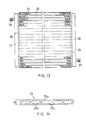
- the multiflow type heat exchangers comprise, for example as shown in Fig. 13, a pair of right and left headers 31 and 32 made of a metal pipe.
- a plurality of flat tubes 33 are connected at their ends to the headers in fluid communication therewith.
- Fins 34 are each interposed two adjacent tubes 33 and 33.
- Partitioning members 35 are each secured inside the headers 31 and 32 at suitable positions intermediate of their ends so that internal spaces of the headers are divided into some longitudinal compartments.
- a coolant passage of a zigzag pattern is formed to start from a coolant inlet 36 at an upper end of one header 31 and then to terminate at a coolant outlet 37 at a lower end of the other header 32 ( as disclosed, for example, in the United States Patent No. 4,825,941 ).
- each of those tubes has a peripheral wall 33a which is of a shape of ellipse in its cross section.
- Each tube has also one or more longitudinal partitions 33b to divide the internal space into some separate coolant paths 33c.
- seam-welded pipes have been proposed for use as the tubes in order to eliminate such a drawback (for example, see the Japanese Patent Publication 62-207572 ).
- the wall of seam-welded tubes can be rendered sufficiently thin to a thickness of about 0.4 to 0.5 mm, remarkably decreasing the tube's height to about 1.5 to 1.7 mm.
- a first object of the present invention which was made to resolve the aforementioned problems is to provide a tube composing heat exchangers which are particularly suited for use as condensers, the tube being not only of a height or thickness suppressed to such a degree as ensuring an improved heat transfer efficiency, but also being of a higher resisting pressure and easy to manufacture.
- a second object of the invention is to provide a method to manufacture a tube for heat exchangers, which tube has such features as just described in respect of the first object.
- the first object is achieved with a tube for heat exchangers which comprises a pair of plane walls spaced a predetermined distance from one another, the plane walls respectively having one lateral ends integrally connected to each other by a U-shaped bent portion, the plane walls further having their other lateral ends which abut against and are tightly secured to one another to define a flat configuration of the tube, one or more curved lugs integral with and protruding inwardly from an inner surface of each plane wall, the curved lugs respectively having innermost tops, with the innermost tops of the curved lugs protruding from one plane wall bear against and integral with the inner surface of the other plane wall or with the innermost tops of the other curved lugs protruding from said other plane wall.
- the first object is achieved with a tube for heat exchangers which comprises a pair of preformed plates spaced a predetermined distance from one another, the preformed plates being tightly secured to one another at both lateral ends to define a flat configuration of the tube, one or more curved lugs integral with and protruding inwardly from an inner surface of each preformed plate, and the curved lugs respectively having innermost tops, with the innermost tops of the curved lugs protruding from one preformed plate bear against and integral with the inner surface of the other preformed plate or with the innermost tops of the other curved lugs protruding from said other preformed plate.
- the second object is accomplished by a method for manufacturing a tube for heat exchangers, the method comprising the steps of: preparing a strip of a predetermined width; forming one or more curved lugs integrally protruding from inner surfaces of both lateral sides of a middle portion of the strip; bending the strip, having the curved lugs, at the middle portion into a U-shape in cross section to form plane walls corresponding to the lateral sides; then abutting lateral extremities of the plane walls one on another; welding the lateral extremities one to another to form an ellipse in cross section such that innermost tops of the curved lugs of one plane wall do engage with the inner surface of the other plane wall or with opposite innermost tops of the other curved lugs of said other plane wall; and then soldering the innermost tops to the inner surface or to the opposite innermost tops with which they are engaging.
- the second object is achieved by a method for manufacturing a tube for heat exchangers, the method comprising the steps of: preparing a strip of predetermined width; forming one or more curved lugs integrally protruding from inner surfaces of both lateral sides of middle portion of strip; bending the strip, having the curved lugs, at the middle portion into a U-shape in cross section to form plane walls corresponding to the lateral sides; then abutting lateral extremities of the plane walls one on another to form an ellipse in cross section such that innermost tops of the curved lugs of one plane wall engage with the inner surface of the other plane wall or with opposite innermost tops of the other curved lugs of said other plane wall; and then soldering in one operation the lateral extremities abutting one on another as well as the innermost tops to the inner surface or to the opposite innermost tops with which they are engaging.
- Each curved lug may be a tightly folded gather extending along the tube. This type of the curved lugs may alternately protrude from one and the other plane walls of the tube so as to divide an internal space thereof into a plurality of separate coolant paths.
- each curved lug may be a dimpled recess also formed integral with either plane wall.
- a plurality of this further type of the curved lugs are distributed over the inner surfaces of either or both plane walls so as to form a zigzag coolant path within the tube.
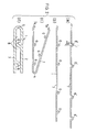
- a tube 1 for heat exchangers comprises a pair of upper and lower plane walls 2 and 3 disposed facing one another and spaced a predetermined distance, for example 0.8 mm, from each other.
- the plane walls 2 and 3 respectively have one lateral ends integrally connected to each other by a U-shaped bent portion 4.
- the plane walls further have their other lateral ends which abut against to be tightly welded one to another at a point 5, thereby forming a flat seam-welded pipe of an ellipse-like shape in its cross section.
- the tube 1 further comprises two curved lugs 6 integral with and protruding inwardly from an inner surface of each plane wall 2 and 3 so that two lugs 6 of one plane wall 2 and two other lugs 6 of the other plane wall 3 alternate in a transverse direction thereof.
- Each curved lug 6 is formed by inwardly recessing a portion of the plane wall 2 or 3 into a V-shape and by subsequently pressing two opposing legs of "V" into close contact with each other, thereby forming a double-ply wall portion.
- the curved lugs thus extend longitudinally of the tube 1.
- An innermost top of each curved lug 6 protruding from one plane wall 2 or 3 bears against the opposite inner surface of the other plane wall 3 or 2.
- the innermost tops are soldered to said opposite inner surface, while the two contacting V-legs of said double-ply wall portion are also soldered integral with each other.
- Such a soldering of the abutting or contacting portions is effected by making use of soldering agent layers of a both-sided aluminum brazing sheet which is used to form the tube. Therefore, the soldering may be performed at the same time as fins 34 and tubes 1 are soldered together and tubes 1 and headers 31 and 32 are soldered together when assembling the heat exchanger.
- the curved lugs 6 function as partitions which divide an internal space of the soldered tube 1 into a plurality of separate coolant paths 8 arranged in the transverse direction of tube 1.
- Wall thickness "t" of the tube 1 may be 0.15 to 0.5 mm, and more preferably 0.4 mm as an example.
- Tube width "w” may be 12 to 20 mm, and more preferably 16 mm as an example, with tube height "h” designed to be 1.2 to 2.0 mm, more preferably to be for example 1.6 mm.
- a strip 7 of the aluminum brazing sheet of a predetermined width is prepared to be processed as shown in Fig. 2b.
- One or more curved lugs 6 are formed by folding longitudinal portions of the strip to protrude in the same direction from surfaces of right and left lateral sides of a transverse middle portion of the strip 7, which portion is bent later. More in detail as shown in Fig. 2a, formed at first are beaded portions 6′ of an "italic-V" shape which has an upright leg perpendicular to the strip surface and an oblique leg inclined toward the upright leg by an angle ⁇ of about 30°. As the next step, each beaded portion 6′ is subjected to a trimming operation wherein the legs thereof are gathered into close contact with each other, thereby producing a desired neat shape of the curved lugs 6 as illustrated in Fig. 2b.
- the strip 7 comprising such curved lugs 6 is bent at its transverse middle portion into a U-shape which has a predetermined radius of curvature, as shown in Fig. 2c.
- Portions adjacent to lateral extremities 7a and 7a are slightly bent in opposite directions so as to abut one on another, with the abutted portions being seam-welded then as denoted by the reference numeral 5 in Fig. 2d.
- Fig. 2d shows the thus manufactured flat tube 1 in part and on an enlarged scale, the tube having a predetermined dimension and being of an ellipse-shape as a whole in its cross section.
- Fig. 3 illustrates a modified tube 1′ comprising curved lugs 6a and 6b which are of a smaller height and protrude from opposite corresponding portions of the upper and lower plane walls 2 and 3, respectively. Innermost tops of the opposite curved lugs 6a and 6b abut one on another and are soldered there to be integral with each other. Other features as well as the manufacturing method are the same as or similar to the tube 1 in the first embodiment.
- Fig. 4 shows a further modified tube 1 ⁇ which comprises the upper and lower strip-like plane walls 2 and 3 spaced apart, for example, 0.8 mm.
- the plane walls have one lateral ends integrally connected by the U-shaped bent portion 4, with other lateral ends being soldered one to another to thereby form a flat tube of an ellipse-shape in cross section.
- the other lateral ends of the walls 2 and 3 have been folded down parallel and inwardly to form creased edges 2a and 3a which are of a predetermined width, before the creased edges 2a and 3a are engaged with and soldered to each other at the region 5.
- Such a binding structure is more advantageous than the simple abutting and soldering of lateral ends as in the other cases already described, because the binding operation is easier and the soldering process in an oven becomes sure and smooth.
- the binding of lateral ends may be effected either by the soldering or the seam-welding method. It is preferable to solder said lateral ends at the same time together with other members of heat exchanger in a one-shot operation, wherein the soldering agent layers of both-sided aluminum brazing sheet may be utilized advantageously.
- the soldering of fins 34 to tubes 1 as well as the soldering thereof to headers 31 and 32 are carried out simultaneously as the lateral ends of tube walls are soldered.
- Fig. 5 shows a still further modified tube 1′′′ comprising curved lugs 6a and 6b which are of a smaller height and protrude from opposite corresponding portions of upper and lower plane walls 2 and 3, respectively. Innermost tops of the opposite curved lugs 6a and 6b abut one on another and are soldered there to be integral with each other.
- Other features of this modified tube and details of its manufacture are the same as or similar to the tube shown in Fig. 4.
- a tube 11 comprises curved lugs 16 which protrude inwardly from separate portions of upper and lower plane walls 12 and 13. Those lugs 16 are provided by recessing the portions of walls 12 and 13 inwardly into semispherical or U-shaped dimple-like shape in cross section. Thus, a plurality of the dimple-like curved lugs 16 are distributed over each plane wall. Respective innermost tops of the lugs 16 on upper wall correspond to and engage with respective innermost tops of the lugs 16 on lower wall so that they are soldered there to be integral with each other.
- An inner space of the tube 11 becomes a single coolant path 18 of a stray or zigzag pattern due to such scattered dimple-like curved lugs 16.
- the coolant flowing through this path 18 in the tube 11 will be stirred by the curved lugs 16 to thereby facilitate the exchange of heat.
- the tube 11 is made from a strip 17 of aluminum brazing sheet, which strip 17 is of a predetermined width as shown in Figs. 7 and 8.
- the dimple-like curved lugs 16 are formed at predetermined points of the strip before it is folded into U-shape in cross section at its transverse middle portion, as shown by the phantom line in Fig. 8. After that, the strip's lateral ends abutting one on another are seam-welded as shown by the numeral 5 so as to define a flat depressed tube.
- the curved lugs 16 on one of the plane walls 12 may also be arranged at positions different from those on the other plane wall 13, in a manner similar to that described hereinbefore. The innermost tops of those lugs engage with the opposite plane wall and are soldered thereto.
- a tube 21 is composed of two preformed plates P1 and P2. Curved lugs 26 protruding inwardly and longitudinally of one plate P1 and other ones 26 of the other plate P2 alternate in the transverse direction thereof.
- the preformed plates are arranged such that their curved lugs are disposed inwardly with lateral ends of said plates, i.e., plane walls, facing one another to be soldered and united.
- the number of curved lugs 26 is two for each preformed plate.
- each preformed plate P1 or P2 Both lateral ends of each preformed plate P1 or P2 are L-shaped bent portions 22a or 23a which abut each other and are soldered to be integral with one another. They may not be soldered but welded, if necessary.
- Other structural features of this tube 21 are the same as those in the first and second embodiments, therefore description thereof being omitted here.
- the third embodiment may also be modified such that the curved lugs 26 on the upper plane wall 22 arranged offset to those on the lower plane wall 23, wherein innermost tops of those lugs are engaged with and soldered to each other.
- the edges of L-shaped bent portions 23a of lower plate P2 may be bent again upwards and inwards, along the full length of tube 21′, into a U-shape.
- Each of the U-shaped edges tightly embraces the corresponding bent portion 22a of upper plate 22a.
- the upper and lower L-shaped portions 22a and 22b are formed at first so that the upper one can be slidingly inserted into the lower one.
- Fig. 11a illustrates a modified means for the preliminary setting, wherein some tongues 23b are formed to protrude from the outer edge of each L-shaped bent portion 23a of the lower plate P2.
- cutouts 22b are formed on each L-shaped bent portion 22a of the upper plate P1.
- the tongues 23b With the upper plate P1 overlying the lower one P2, the tongues 23b are bent towards the cutouts 22b and folded down onto the edges of L-shaped portion, thereby binding the plates to form a tube 21" as shown in Fig. 11b.
- Fig. 12a illustrates another modification in which small round ribs 23c protrude upwardly of the L-shaped bent portions 23a of lower plate P2.
- Respective holes 22c which are formed through the bent portions 22a of upper plate P1 correspond to the respective ribs 23c.
- Tube 21′′′ is assembled as shown in Fig. 12b, by placing the upper plate P1 upon the lower one P2 and then caulking the tops of ribs 23c projecting through the holes 22c so as to secure the ribs therein.
- those lugs 16 may be dimple-like protrusions which are formed by recessing the portions of plane walls 22 and 23 inwardly into semispherical shape or U-shape in cross section. In such a case, a plurality of the dimple-like protrusions are distributed over each plane wall. Innermost tops of the upper and lower corresponding protrusions are engaged and soldered integral with each other . Thus, an inner space of the tube becomes a single coolant path of a stray pattern due to such scattered dimple-like protrusions. The coolant flowing through this path will be stirred and assisted by the protrusions to accelerate the heat exchange.
- bent portions of lateral ends may not be bent outwards as in the third embodiment but alternatively be bent inwards.
- the tube comprises so thin walls that its height is minimized rendering it to be one of the thinnest types.
- the curved lugs which protrude from the upper and lower plane walls so as to be engaged and soldered to one another or to the opposite inner surface of the wall, can function as the reinforcing members of the tube, thereby improving its compressive strength and its resistance to internal pressure.
- the tube provided for condensers according to the invention is by no means inferior to the flat extruded tube of prior art.
- the tube of the invention it is needed merely to apply the conventional integrating technology to the single strip or two plates on which the predetermined curved lugs have been formed. Therefore, the manufacturing process does not involve any difficulty to produce the tubes at a higher productivity and lower manufacturing cost.
- the curved lugs extend longitudinally of the tube, its resisting pressure and its flexing strength are increased advantageously.
- the coolant is so effectively stirred, while flowing through the tubes' internal paths in the tubes, that their heat exchange efficiency is improved to a remarkable degree.
Landscapes
- Engineering & Computer Science (AREA)
- Physics & Mathematics (AREA)
- Thermal Sciences (AREA)
- Mechanical Engineering (AREA)
- General Engineering & Computer Science (AREA)
- Heat-Exchange Devices With Radiators And Conduit Assemblies (AREA)
- Making Paper Articles (AREA)
- Rigid Pipes And Flexible Pipes (AREA)
- Details Of Heat-Exchange And Heat-Transfer (AREA)
Applications Claiming Priority (6)
| Application Number | Priority Date | Filing Date | Title |
|---|---|---|---|
| JP122289/90 | 1990-05-11 | ||
| JP2122289A JPH0420791A (ja) | 1990-05-11 | 1990-05-11 | 熱交換器用チューブ及びその製造方法 |
| JP200206/90 | 1990-06-27 | ||
| JP20020690A JPH0486489A (ja) | 1990-07-27 | 1990-07-27 | 熱交換器用チューブ |
| AU83781/91A AU646288B2 (en) | 1990-05-11 | 1991-09-10 | Tube for heat exchangers and a method for manufacturing the tube |
| CA002054484A CA2054484C (en) | 1990-05-11 | 1991-10-29 | Tube for heat exchangers and a method for manufacturing the tube |
Publications (2)
| Publication Number | Publication Date |
|---|---|
| EP0457470A1 true EP0457470A1 (de) | 1991-11-21 |
| EP0457470B1 EP0457470B1 (de) | 1996-01-03 |
Family
ID=27423957
Family Applications (1)
| Application Number | Title | Priority Date | Filing Date |
|---|---|---|---|
| EP91304036A Expired - Lifetime EP0457470B1 (de) | 1990-05-11 | 1991-05-03 | Rohr für Wärmetauscher und Verfahren zur Herstellung des Rohrs |
Country Status (6)
| Country | Link |
|---|---|
| US (2) | US5186250A (de) |
| EP (1) | EP0457470B1 (de) |
| AT (1) | ATE132615T1 (de) |
| AU (1) | AU646288B2 (de) |
| CA (1) | CA2054484C (de) |
| DE (1) | DE69115986T2 (de) |
Cited By (26)
| Publication number | Priority date | Publication date | Assignee | Title |
|---|---|---|---|---|
| EP0632245A1 (de) * | 1993-07-01 | 1995-01-04 | THERMAL-WERKE Wärme-, Kälte-, Klimatechnik GmbH | Wasser/Luft-Wärmetauscher aus Aluminium für Kraftfahrzeuge |
| DE9318525U1 (de) * | 1993-12-03 | 1995-04-06 | Thermal-Werke, Wärme-, Kälte-, Klimatechnik GmbH, 68766 Hockenheim | Wasser/Luft-Wärmetauscher aus Aluminium für Kraftfahrzeuge |
| FR2732101A1 (fr) * | 1995-03-22 | 1996-09-27 | Behr Gmbh & Co | Tube plat pour echangeur de chaleur assemble par brasage ainsi que procede de fabrication et utilisation d'un tel tube |
| EP0815971A1 (de) * | 1996-06-26 | 1998-01-07 | Showa Aluminum Corporation | Verfahren zur Herstellung von Flachröhren für Wärmetauscher |
| EP0724125A3 (de) * | 1995-01-27 | 1998-01-14 | Zexel Corporation | Flachrohr für Wärmetauscher und Verfahren zu dessen Herstellung |
| FR2757258A1 (fr) | 1996-12-12 | 1998-06-19 | Valeo Equip Electr Moteur | Tube plat a plusieurs canaux pour echangeur de chaleur |
| FR2757615A1 (fr) * | 1996-12-24 | 1998-06-26 | Valeo Thermique Moteur Sa | Tube lamine, notamment pour un echangeur de chaleur de vehicule automobile |
| EP0854343A2 (de) * | 1997-01-20 | 1998-07-22 | Zexel Corporation | Wärmetauscher und Verfahren zu dessen Herstellung |
| FR2764647A1 (fr) * | 1997-06-17 | 1998-12-18 | Valeo Thermique Moteur Sa | Refroidisseur d'air de suralimentation de construction economique |
| EP0907062A1 (de) * | 1997-03-28 | 1999-04-07 | Sanden Corporation | Wärmetauscherrohr und verfahren zu dessen herstellung |
| EP0840081A3 (de) * | 1996-10-29 | 1999-04-14 | Denso Corporation | Wärmetauscher und Verfahren zu dessen Herstellung |
| EP0880002A3 (de) * | 1997-05-19 | 1999-08-04 | Zexel Corporation | Wärmetauscher |
| EP1027942A1 (de) * | 1997-07-09 | 2000-08-16 | Zexel Corporation | Rohr für wärmetauscher und verfahren zur herstellung |
| EP1074807A3 (de) * | 1999-08-02 | 2001-04-11 | Ford Motor Company | Gebogenes Rohr für Wärmetauscher und dessen Herstellung |
| EP1106949A1 (de) * | 1999-12-10 | 2001-06-13 | Visteon Global Technologies, Inc. | Gebogenes Rohr für Wärmetauscher und dessen Herstellung |
| AU739859B2 (en) * | 1999-05-31 | 2001-10-25 | Mitsubishi Heavy Industries, Ltd. | Heat exchanger |
| DE19723801C2 (de) * | 1996-06-06 | 2002-04-18 | Zexel Valeo Climate Contr Corp | Wärmetauscher |
| EP1253391A1 (de) | 2001-04-28 | 2002-10-30 | Behr GmbH & Co. | Gefalztes Mehrkammerflachrohr |
| WO2003060412A2 (de) | 2002-01-17 | 2003-07-24 | Behr Gmbh & Co. | Geschweisstes mehrkammerrohr |
| WO2003060410A1 (de) | 2002-01-17 | 2003-07-24 | Behr Gmbh & Co. | Mehrkammerflachrohr |
| DE10343905A1 (de) * | 2003-09-19 | 2005-06-09 | Behr Gmbh & Co. Kg | Gelötetes Wärmeübertragernetz |
| WO2007113317A1 (en) * | 2006-04-05 | 2007-10-11 | Valeo Termico S.A. | Procedure for manufacture of a tube for conveyance of a fluid of a heat exchanger, and tube obtained by such procedure |
| WO2012110036A1 (en) * | 2011-02-18 | 2012-08-23 | Nissens A/S | Method of producing a heat exchanger and a heat exchanger |
| WO2017134359A1 (fr) * | 2016-02-05 | 2017-08-10 | Valeo Systemes Thermiques | Échangeur de chaleur a tubes améliorés |
| WO2019115942A1 (fr) * | 2017-12-14 | 2019-06-20 | Valeo Systemes Thermiques | Dispositif de régulation thermique à plaques pour module de batteries |
| EP3665428A4 (de) * | 2017-08-07 | 2021-05-05 | Modine Manufacturing Company | Wärmetauscherröhre |
Families Citing this family (119)
| Publication number | Priority date | Publication date | Assignee | Title |
|---|---|---|---|---|
| JP3113100B2 (ja) * | 1992-11-05 | 2000-11-27 | 株式会社デンソー | 多穴管押出用ダイス及び多穴管 |
| JP3364665B2 (ja) * | 1993-03-26 | 2003-01-08 | 昭和電工株式会社 | 熱交換器用冷媒流通管 |
| US5931226A (en) * | 1993-03-26 | 1999-08-03 | Showa Aluminum Corporation | Refrigerant tubes for heat exchangers |
| US5784776A (en) * | 1993-06-16 | 1998-07-28 | Showa Aluminum Corporation | Process for producing flat heat exchange tubes |
| CN1132552A (zh) * | 1993-08-04 | 1996-10-02 | 因西尔科公司热部件部门 | 散热管及其制造方法和设备 |
| US5441105A (en) * | 1993-11-18 | 1995-08-15 | Wynn's Climate Systems, Inc. | Folded parallel flow condenser tube |
| JPH07180984A (ja) * | 1993-12-21 | 1995-07-18 | Sanden Corp | 熱交換器及びその製造方法 |
| JPH07227631A (ja) * | 1993-12-21 | 1995-08-29 | Zexel Corp | 積層型熱交換器の熱交換用導管及びその製造方法 |
| US5799397A (en) * | 1994-03-29 | 1998-09-01 | Calsonic Corporation | Pipe with closure portion, heat exchanger header and method of producing therefor |
| US5511613A (en) | 1994-12-12 | 1996-04-30 | Hudson Products Corporation | Elongated heat exchanger tubes having internal stiffening structure |
| US20040079522A1 (en) * | 1995-11-13 | 2004-04-29 | Roger Paulman | Folded, bent and re-expanded heat exchanger tube and assemblies |
| US5579837A (en) * | 1995-11-15 | 1996-12-03 | Ford Motor Company | Heat exchanger tube and method of making the same |
| FR2749648B1 (fr) * | 1996-06-05 | 1998-09-04 | Valeo Thermique Moteur Sa | Tube plat a entretoise mediane pour echangeur de chaleur |
| KR100261006B1 (ko) * | 1996-07-03 | 2000-07-01 | 오타 유다카 | 열교환기용 편평튜우브 |
| JP3692654B2 (ja) * | 1996-09-16 | 2005-09-07 | 株式会社デンソー | 偏平チューブのロール成形方法及び装置 |
| US5979548A (en) * | 1996-12-23 | 1999-11-09 | Fafco, Inc. | Heat exchanger having heat exchange tubes with angled heat-exchange performance-improving indentations |
| DE19654363B4 (de) * | 1996-12-24 | 2007-09-27 | Behr Gmbh & Co. Kg | Abgaswärmeübertrager für einen Verbrennungsmotor |
| DE29705396U1 (de) * | 1997-03-25 | 1998-08-13 | Elpag Ag Chur, Chur | Wärmetauscher mit ungleichmäßiger Anordnung der Mediumführungselemente |
| US5881457A (en) * | 1997-05-29 | 1999-03-16 | Ford Motor Company | Method of making refrigerant tubes for heat exchangers |
| JP3212268B2 (ja) * | 1997-08-08 | 2001-09-25 | 株式会社ゼクセルヴァレオクライメートコントロール | 熱交換器用チューブとその製造方法 |
| US5890288A (en) * | 1997-08-21 | 1999-04-06 | Ford Motor Company | Method for making a heat exchanger tube |
| US5934365A (en) * | 1997-08-21 | 1999-08-10 | Ford Motor Company | Heat exchanger |
| JP3299148B2 (ja) * | 1997-09-16 | 2002-07-08 | 株式会社ゼクセルヴァレオクライメートコントロール | 熱交換器用チューブとその製造方法 |
| DE19755037A1 (de) * | 1997-12-11 | 1999-06-17 | Behr Gmbh & Co | Wärmeübertrager und Verfahren zu seiner Herstellung |
| US6024086A (en) * | 1998-07-22 | 2000-02-15 | Rich; Albert Clark | Solar energy collector having oval absorption tubes |
| CA2289428C (en) * | 1998-12-04 | 2008-12-09 | Beckett Gas, Inc. | Heat exchanger tube with integral restricting and turbulating structure |
| US8459342B2 (en) * | 2003-11-25 | 2013-06-11 | Beckett Gas, Inc. | Heat exchanger tube with integral restricting and turbulating structure |
| FR2787180B1 (fr) * | 1998-12-11 | 2001-03-02 | Valeo Thermique Moteur Sa | Tube plie pour echangeur de chaleur et procede pour sa conformation |
| EP1022532A3 (de) * | 1999-01-19 | 2001-08-01 | Calsonic Kansei Corporation | Flachröhren für Wärmetauscher und Verfahren zu deren Herstellung |
| DE29906337U1 (de) | 1999-04-09 | 1999-07-01 | Behr Gmbh & Co, 70469 Stuttgart | Wärmeübertrager, insbesondere Kondensator für Kraftfahrzeugklimaanlagen |
| DE19920102B4 (de) * | 1999-05-03 | 2009-01-02 | Behr Gmbh & Co. Kg | Mehrkammerrohr und Wärmeübertrageranordnung für ein Kraftfahrzeug |
| US6332495B1 (en) * | 1999-06-02 | 2001-12-25 | Long Manufacturing Ltd. | Clip on manifold heat exchanger |
| CA2273456C (en) * | 1999-06-02 | 2008-09-23 | Long Manufacturing Ltd. | Clip on manifold heat exchanger |
| US6530424B2 (en) * | 1999-06-02 | 2003-03-11 | Long Manufacturing Ltd. | Clip on manifold heat exchanger |
| US6318455B1 (en) * | 1999-07-14 | 2001-11-20 | Mitsubishi Heavy Industries, Ltd. | Heat exchanger |
| US6988539B2 (en) * | 2000-01-07 | 2006-01-24 | Zexel Valeo Climate Control Corporation | Heat exchanger |
| JP2001201286A (ja) * | 2000-01-21 | 2001-07-27 | Mitsubishi Heavy Ind Ltd | 熱交換チューブ |
| DE10033070A1 (de) * | 2000-03-31 | 2002-01-17 | Modine Mfg Co | Kühler für Kraftfahrzeuge sowie Herstellungsverfahren |
| US6594897B2 (en) * | 2000-07-25 | 2003-07-22 | Mando Climate Control Corporation | Method for manufacturing coolant tube of heat exchanger |
| AU2001281638A1 (en) * | 2000-08-16 | 2002-02-25 | Max Roth | Heat exchanger |
| US6536255B2 (en) | 2000-12-07 | 2003-03-25 | Brazeway, Inc. | Multivoid heat exchanger tubing with ultra small voids and method for making the tubing |
| DE10137334A1 (de) * | 2001-07-31 | 2003-02-27 | Modine Mfg Co | Flachrohr, Herstellungsverfahren, Wärmetauscher |
| US20030031689A1 (en) * | 2001-08-09 | 2003-02-13 | Thomas Mammone | Method of skin exfoliation |
| DE10147192A1 (de) | 2001-09-25 | 2003-04-17 | Modine Mfg Co | Wärmeaustauscher mit einem Rippen-Flachrohr-Block und Herstellungsverfahren |
| US20030131976A1 (en) * | 2002-01-11 | 2003-07-17 | Krause Paul E. | Gravity fed heat exchanger |
| US6819561B2 (en) | 2002-02-22 | 2004-11-16 | Satcon Technology Corporation | Finned-tube heat exchangers and cold plates, self-cooling electronic component systems using same, and methods for cooling electronic components using same |
| BR0306209A (pt) | 2002-08-31 | 2004-08-24 | Behr Gmbh & Co | Condensador de agente de refrigeração, especialmente para instalações de ar condicionado em automóveis |
| EP1546630A4 (de) * | 2002-10-02 | 2010-11-24 | Showa Denko Kk | WûRMEAUSTAUSCHROHR UND WûRMEAUSTAUSCHER |
| FR2845747B1 (fr) * | 2002-10-15 | 2005-08-19 | Advanced Automation | Dispositif de transmission et application a un dispositif de dosage |
| JP2004263997A (ja) * | 2003-03-04 | 2004-09-24 | Calsonic Kansei Corp | エバポレータ |
| DE10328001A1 (de) * | 2003-06-21 | 2005-01-05 | Modine Manufacturing Co., Racine | Flaches Wärmetauscherrohr |
| KR20050030490A (ko) * | 2003-09-26 | 2005-03-30 | 엘에스전선 주식회사 | 열교환기 |
| DE102004036020A1 (de) * | 2004-07-23 | 2006-02-16 | Behr Gmbh & Co. Kg | Wärmeübertrager, insbesondere Kondensator |
| DE102004041101A1 (de) | 2004-08-24 | 2006-03-02 | Behr Gmbh & Co. Kg | Flachrohr für einen Wärmeübertrager, insbesondere für Kraftfahrzeuge und Verfahren zur Herstellung eines Flachrohres |
| DE102004049809A1 (de) * | 2004-10-12 | 2006-04-13 | Behr Gmbh & Co. Kg | Flachrohr für Wärmetauscher |
| EP1802932B1 (de) * | 2004-10-22 | 2009-06-03 | Aleris Aluminum Koblenz GmbH | Aus einem profilgewalzten metallprodukt hergestelltes rohr und herstellungsverfahren dafür |
| DE102005013777A1 (de) * | 2005-03-22 | 2006-09-28 | Behr Gmbh & Co. Kg | Rohr für einen Wärmetauscher |
| US7259965B2 (en) * | 2005-04-07 | 2007-08-21 | Intel Corporation | Integrated circuit coolant microchannel assembly with targeted channel configuration |
| US8091621B2 (en) * | 2006-01-19 | 2012-01-10 | Modine Manufacturing Company | Flat tube, flat tube heat exchanger, and method of manufacturing same |
| US20090014165A1 (en) * | 2006-01-19 | 2009-01-15 | Werner Zobel | Flat tube, flat tube heat exchanger, and method of manufacturing same |
| US7921559B2 (en) * | 2006-01-19 | 2011-04-12 | Modine Manufacturing Company | Flat tube, flat tube heat exchanger, and method of manufacturing same |
| JP2009524003A (ja) * | 2006-01-19 | 2009-06-25 | モーディーン・マニュファクチャリング・カンパニー | フラットチューブ、フラットチューブ型熱交換器及びその製造方法 |
| US8438728B2 (en) * | 2006-01-19 | 2013-05-14 | Modine Manufacturing Company | Flat tube, flat tube heat exchanger, and method of manufacturing same |
| US20090019696A1 (en) * | 2006-01-19 | 2009-01-22 | Werner Zobel | Flat tube, flat tube heat exchanger, and method of manufacturing same |
| US8191258B2 (en) * | 2006-01-19 | 2012-06-05 | Modine Manufacturing Company | Flat tube, flat tube heat exchanger, and method of manufacturing same |
| US8683690B2 (en) * | 2006-01-19 | 2014-04-01 | Modine Manufacturing Company | Flat tube, flat tube heat exchanger, and method of manufacturing same |
| US8434227B2 (en) | 2006-01-19 | 2013-05-07 | Modine Manufacturing Company | Method of forming heat exchanger tubes |
| US8281489B2 (en) * | 2006-01-19 | 2012-10-09 | Modine Manufacturing Company | Flat tube, flat tube heat exchanger, and method of manufacturing same |
| DE102006019823B4 (de) * | 2006-04-28 | 2011-01-27 | Arup Alu-Rohr Und -Profil Gmbh | Verfahren und Vorrichtung zur Herstellung von Rohren |
| FR2901016B1 (fr) * | 2006-05-12 | 2008-07-18 | Kapp France Sa | Echangeur de chaleur a plaques d'echange soudees |
| ES2373736T3 (es) * | 2006-08-31 | 2012-02-08 | Aurubis Ag | Un procedimiento para producir un tubo metálico revistiendo con rodillos al menos dos perfiles para formar al menos tres canales. |
| KR101250771B1 (ko) * | 2006-09-21 | 2013-04-04 | 한라공조주식회사 | 열교환기 |
| US20080078536A1 (en) * | 2006-09-29 | 2008-04-03 | International Truck Intellectual Property Company, Llc | Corrosion resistant bi-metal charge air cooler |
| US20080142202A1 (en) * | 2006-12-15 | 2008-06-19 | Valeo, Inc. | High strength fin louver design |
| DE102007004993A1 (de) | 2007-02-01 | 2008-08-07 | Modine Manufacturing Co., Racine | Herstellungsverfahren für Flachrohre und Walzenstraße |
| DE102007006664A1 (de) * | 2007-02-10 | 2008-08-14 | Modine Manufacturing Co., Racine | Flachrohr für Wärmetauscher |
| CN101925791A (zh) * | 2007-11-30 | 2010-12-22 | 霍尔泰克国际股份有限公司 | 用于风冷式热交换器的翅片管装置及其制造方法 |
| FR2929390B1 (fr) * | 2008-03-26 | 2014-10-10 | Valeo Systemes Thermiques | Plaque d'echangeur de chaleur |
| US9759495B2 (en) * | 2008-06-30 | 2017-09-12 | Lg Chem, Ltd. | Battery cell assembly having heat exchanger with serpentine flow path |
| US8234881B2 (en) * | 2008-08-28 | 2012-08-07 | Johnson Controls Technology Company | Multichannel heat exchanger with dissimilar flow |
| DE102008064090A1 (de) * | 2008-12-19 | 2010-08-12 | Mahle International Gmbh | Abgaskühler |
| CN101832726B (zh) * | 2009-03-11 | 2012-01-25 | 三花丹佛斯(杭州)微通道换热器有限公司 | 一种用于热交换器的散热管及其制造方法 |
| US20100275619A1 (en) * | 2009-04-30 | 2010-11-04 | Lg Chem, Ltd. | Cooling system for a battery system and a method for cooling the battery system |
| EP2306134B1 (de) * | 2009-10-01 | 2012-05-30 | Techspace Aero S.A. | Verfahren zur Herstellung eines Wärmetauschers und durch dieses Verfahren erhaltener Wärmetauscher |
| US20120198882A1 (en) * | 2009-10-19 | 2012-08-09 | Showa Denko K.K. | Evaporator |
| DE102009055608A1 (de) * | 2009-11-25 | 2011-05-26 | Behr Gmbh & Co. Kg | Gelöteter Aluminium-Wärmeübertrager |
| US8844472B2 (en) * | 2009-12-22 | 2014-09-30 | Lochinvar, Llc | Fire tube heater |
| DE102010023384B4 (de) | 2010-06-10 | 2014-08-28 | Modine Manufacturing Co. | Herstellungsverfahren, insbesondere für Rohre und Abreißvorrichtung |
| ITTO20100884A1 (it) * | 2010-11-05 | 2012-05-06 | Denso Thermal Systems Spa | Tubo multicanale di lamiera ripiegata per scambiatori di calore |
| US8661676B2 (en) * | 2011-03-29 | 2014-03-04 | Frank G. McNulty | Rotary die forming process and apparatus for fabricating multi-port tubes |
| US9605914B2 (en) | 2012-03-29 | 2017-03-28 | Lg Chem, Ltd. | Battery system and method of assembling the battery system |
| US9105950B2 (en) | 2012-03-29 | 2015-08-11 | Lg Chem, Ltd. | Battery system having an evaporative cooling member with a plate portion and a method for cooling the battery system |
| US9379420B2 (en) | 2012-03-29 | 2016-06-28 | Lg Chem, Ltd. | Battery system and method for cooling the battery system |
| US8852781B2 (en) | 2012-05-19 | 2014-10-07 | Lg Chem, Ltd. | Battery cell assembly and method for manufacturing a cooling fin for the battery cell assembly |
| CN102706199A (zh) * | 2012-05-25 | 2012-10-03 | 锦州秀亭制管有限公司 | 刺凸式换热管及其制造工艺 |
| US9306199B2 (en) | 2012-08-16 | 2016-04-05 | Lg Chem, Ltd. | Battery module and method for assembling the battery module |
| EP2703765B1 (de) * | 2012-08-27 | 2017-10-25 | Kelvion PHE GmbH | Plattenwärmetauscher-System |
| US9083066B2 (en) | 2012-11-27 | 2015-07-14 | Lg Chem, Ltd. | Battery system and method for cooling a battery cell assembly |
| US9453599B2 (en) * | 2013-06-21 | 2016-09-27 | Ford Global Technologies, Llc | Bi-channel coolant tube having crossover channels to allow coolant interaction |
| US9184424B2 (en) | 2013-07-08 | 2015-11-10 | Lg Chem, Ltd. | Battery assembly |
| US20150026981A1 (en) * | 2013-07-24 | 2015-01-29 | Asia Vital Components Co., Ltd. | Manufacturing mehtod of vapor chamber structure |
| JP6194700B2 (ja) * | 2013-08-30 | 2017-09-13 | 富士通株式会社 | 放熱器および放熱器の製造方法 |
| US9444124B2 (en) | 2014-01-23 | 2016-09-13 | Lg Chem, Ltd. | Battery cell assembly and method for coupling a cooling fin to first and second cooling manifolds |
| CN103909392A (zh) * | 2014-03-12 | 2014-07-09 | 无为虹波电器有限公司 | 一种电热管的成型工艺 |
| DE102014206612A1 (de) * | 2014-04-04 | 2015-10-29 | Mahle International Gmbh | Wärmetauscher |
| US10084218B2 (en) | 2014-05-09 | 2018-09-25 | Lg Chem, Ltd. | Battery pack and method of assembling the battery pack |
| US10770762B2 (en) | 2014-05-09 | 2020-09-08 | Lg Chem, Ltd. | Battery module and method of assembling the battery module |
| US10139172B2 (en) * | 2014-08-28 | 2018-11-27 | Mahle International Gmbh | Heat exchanger fin retention feature |
| US9484559B2 (en) | 2014-10-10 | 2016-11-01 | Lg Chem, Ltd. | Battery cell assembly |
| US9412980B2 (en) | 2014-10-17 | 2016-08-09 | Lg Chem, Ltd. | Battery cell assembly |
| US9786894B2 (en) | 2014-11-03 | 2017-10-10 | Lg Chem, Ltd. | Battery pack |
| US9627724B2 (en) | 2014-12-04 | 2017-04-18 | Lg Chem, Ltd. | Battery pack having a cooling plate assembly |
| JP7091308B2 (ja) * | 2017-03-03 | 2022-06-27 | 株式会社ティラド | ドロンカップ型熱交換器 |
| CN108788627A (zh) * | 2017-05-02 | 2018-11-13 | 南宁市安和机械设备有限公司 | 一种高频焊b型散热管成型工艺 |
| US10495167B2 (en) * | 2017-08-16 | 2019-12-03 | The Legion Engineering Corporation | Heat dissipating device for braking system |
| CN209310597U (zh) | 2018-12-18 | 2019-08-27 | 杭州三花微通道换热器有限公司 | 换热管及具有该换热管的换热器 |
| KR102147124B1 (ko) * | 2019-04-16 | 2020-08-31 | 주식회사 폴라앤코 | 주입관이 없는 휴대 전자기기용 박막 증기챔버 및 이의 제조방법 |
| US11805945B2 (en) * | 2019-09-18 | 2023-11-07 | Robert G. Nothum, Jr. | Heat exchange tubes for fryer in food process line |
| CN112845940B (zh) * | 2020-12-31 | 2024-09-10 | 南宁市安和机械设备有限公司 | 一种耐压油冷器管的制作工艺 |
Citations (8)
| Publication number | Priority date | Publication date | Assignee | Title |
|---|---|---|---|---|
| BE517964A (de) * | ||||
| FR358914A (fr) * | 1905-10-27 | 1906-03-12 | Charles Baudier | Refroidisseur pour moteurs à explosions |
| DE1501537A1 (de) * | 1965-07-17 | 1969-06-26 | Inst Leichtbau Und Oekonomisch | Kreuzstrom-Waermetauscher |
| FR2156359A1 (de) * | 1971-10-15 | 1973-05-25 | Union Carbide Corp | |
| DE3245531A1 (de) * | 1982-12-09 | 1984-06-14 | Vyzk Ustav Silnoproude Elekt | Gerippter bestandteil, dessen rippen durch zusammengepresste blechdurchbiegungen gebildet sind |
| DE3704215A1 (de) * | 1987-02-11 | 1988-08-25 | Laengerer & Reich Kuehler | Strangpressprofilrohr fuer waermeaustauscher |
| EP0283937A1 (de) * | 1987-03-25 | 1988-09-28 | Nihon Radiator Co., Ltd. | Flachrohr für Wärmetauscher mit eingesetzter Rippe |
| GB2223091A (en) * | 1988-08-12 | 1990-03-28 | Calsonic Corp | Heat exchange tubes |
Family Cites Families (15)
| Publication number | Priority date | Publication date | Assignee | Title |
|---|---|---|---|---|
| US349060A (en) * | 1886-09-14 | P- serve | ||
| US1316199A (en) * | 1919-09-16 | Philmobb iv spebt | ||
| US1302627A (en) * | 1915-05-17 | 1919-05-06 | Kinderman M Boblett | Automobile-radiator. |
| US1215793A (en) * | 1915-09-20 | 1917-02-13 | John B Gabrielson | Radiator. |
| US2093256A (en) * | 1935-01-10 | 1937-09-14 | Still William Joseph | Heat exchange element |
| US2151540A (en) * | 1935-06-19 | 1939-03-21 | Varga Alexander | Heat exchanger and method of making same |
| US3603384A (en) * | 1969-04-08 | 1971-09-07 | Modine Mfg Co | Expandable tube, and heat exchanger |
| US3662582A (en) * | 1970-05-18 | 1972-05-16 | Noranda Metal Ind | Heat-exchange tubing and method of making it |
| US3757856A (en) * | 1971-10-15 | 1973-09-11 | Union Carbide Corp | Primary surface heat exchanger and manufacture thereof |
| JPS597446A (ja) * | 1982-07-02 | 1984-01-14 | Nippon Denso Co Ltd | 偏平チューブとコルゲートフィンの組付方法 |
| JPS6167529A (ja) * | 1984-09-07 | 1986-04-07 | Showa Alum Corp | インナ−フインを備えた熱交換管の製造法 |
| US4688311A (en) * | 1986-03-03 | 1987-08-25 | Modine Manufacturing Company | Method of making a heat exchanger |
| US4825941B1 (en) * | 1986-07-29 | 1997-07-01 | Showa Aluminum Corp | Condenser for use in a car cooling system |
| JPH02108411A (ja) * | 1988-10-17 | 1990-04-20 | Sumitomo Light Metal Ind Ltd | 熱交換管の製造法および製造装置 |
| JP2968815B2 (ja) * | 1990-04-18 | 1999-11-02 | 三井化学株式会社 | 共重合体の製造方法 |
-
1991
- 1991-04-29 US US07/693,955 patent/US5186250A/en not_active Expired - Lifetime
- 1991-05-03 AT AT91304036T patent/ATE132615T1/de not_active IP Right Cessation
- 1991-05-03 EP EP91304036A patent/EP0457470B1/de not_active Expired - Lifetime
- 1991-05-03 DE DE69115986T patent/DE69115986T2/de not_active Expired - Fee Related
- 1991-09-10 AU AU83781/91A patent/AU646288B2/en not_active Ceased
- 1991-10-29 CA CA002054484A patent/CA2054484C/en not_active Expired - Fee Related
-
1994
- 1994-03-17 US US08/210,749 patent/US5386629A/en not_active Expired - Lifetime
Patent Citations (8)
| Publication number | Priority date | Publication date | Assignee | Title |
|---|---|---|---|---|
| BE517964A (de) * | ||||
| FR358914A (fr) * | 1905-10-27 | 1906-03-12 | Charles Baudier | Refroidisseur pour moteurs à explosions |
| DE1501537A1 (de) * | 1965-07-17 | 1969-06-26 | Inst Leichtbau Und Oekonomisch | Kreuzstrom-Waermetauscher |
| FR2156359A1 (de) * | 1971-10-15 | 1973-05-25 | Union Carbide Corp | |
| DE3245531A1 (de) * | 1982-12-09 | 1984-06-14 | Vyzk Ustav Silnoproude Elekt | Gerippter bestandteil, dessen rippen durch zusammengepresste blechdurchbiegungen gebildet sind |
| DE3704215A1 (de) * | 1987-02-11 | 1988-08-25 | Laengerer & Reich Kuehler | Strangpressprofilrohr fuer waermeaustauscher |
| EP0283937A1 (de) * | 1987-03-25 | 1988-09-28 | Nihon Radiator Co., Ltd. | Flachrohr für Wärmetauscher mit eingesetzter Rippe |
| GB2223091A (en) * | 1988-08-12 | 1990-03-28 | Calsonic Corp | Heat exchange tubes |
Cited By (36)
| Publication number | Priority date | Publication date | Assignee | Title |
|---|---|---|---|---|
| EP0632245A1 (de) * | 1993-07-01 | 1995-01-04 | THERMAL-WERKE Wärme-, Kälte-, Klimatechnik GmbH | Wasser/Luft-Wärmetauscher aus Aluminium für Kraftfahrzeuge |
| DE9318525U1 (de) * | 1993-12-03 | 1995-04-06 | Thermal-Werke, Wärme-, Kälte-, Klimatechnik GmbH, 68766 Hockenheim | Wasser/Luft-Wärmetauscher aus Aluminium für Kraftfahrzeuge |
| EP0724125A3 (de) * | 1995-01-27 | 1998-01-14 | Zexel Corporation | Flachrohr für Wärmetauscher und Verfahren zu dessen Herstellung |
| FR2732101A1 (fr) * | 1995-03-22 | 1996-09-27 | Behr Gmbh & Co | Tube plat pour echangeur de chaleur assemble par brasage ainsi que procede de fabrication et utilisation d'un tel tube |
| DE19723801C2 (de) * | 1996-06-06 | 2002-04-18 | Zexel Valeo Climate Contr Corp | Wärmetauscher |
| EP0815971A1 (de) * | 1996-06-26 | 1998-01-07 | Showa Aluminum Corporation | Verfahren zur Herstellung von Flachröhren für Wärmetauscher |
| EP1180403A1 (de) * | 1996-06-26 | 2002-02-20 | Showa Denko K.K. | Verfahren zur Herstellung von Flachröhren für Wärmetauscher |
| US5947365A (en) * | 1996-06-26 | 1999-09-07 | Showa Aluminum Corporation | Process for producing flat heat exchange tubes |
| EP0840081A3 (de) * | 1996-10-29 | 1999-04-14 | Denso Corporation | Wärmetauscher und Verfahren zu dessen Herstellung |
| US6206089B1 (en) | 1996-10-29 | 2001-03-27 | Denso Corporation | Heat exchanger and method for manufacturing the same |
| FR2757258A1 (fr) | 1996-12-12 | 1998-06-19 | Valeo Equip Electr Moteur | Tube plat a plusieurs canaux pour echangeur de chaleur |
| FR2757615A1 (fr) * | 1996-12-24 | 1998-06-26 | Valeo Thermique Moteur Sa | Tube lamine, notamment pour un echangeur de chaleur de vehicule automobile |
| EP0854343A3 (de) * | 1997-01-20 | 1999-03-17 | Zexel Corporation | Wärmetauscher und Verfahren zu dessen Herstellung |
| EP0854343A2 (de) * | 1997-01-20 | 1998-07-22 | Zexel Corporation | Wärmetauscher und Verfahren zu dessen Herstellung |
| EP0907062A1 (de) * | 1997-03-28 | 1999-04-07 | Sanden Corporation | Wärmetauscherrohr und verfahren zu dessen herstellung |
| EP0907062A4 (de) * | 1997-03-28 | 1999-11-24 | Sanden Corp | Wärmetauscherrohr und verfahren zu dessen herstellung |
| EP0880002A3 (de) * | 1997-05-19 | 1999-08-04 | Zexel Corporation | Wärmetauscher |
| FR2764647A1 (fr) * | 1997-06-17 | 1998-12-18 | Valeo Thermique Moteur Sa | Refroidisseur d'air de suralimentation de construction economique |
| EP1027942A4 (de) * | 1997-07-09 | 2001-05-16 | Zexel Valeo Climate Contr Corp | Rohr für wärmetauscher und verfahren zur herstellung |
| EP1027942A1 (de) * | 1997-07-09 | 2000-08-16 | Zexel Corporation | Rohr für wärmetauscher und verfahren zur herstellung |
| AU739859B2 (en) * | 1999-05-31 | 2001-10-25 | Mitsubishi Heavy Industries, Ltd. | Heat exchanger |
| EP1074807A3 (de) * | 1999-08-02 | 2001-04-11 | Ford Motor Company | Gebogenes Rohr für Wärmetauscher und dessen Herstellung |
| EP1106949A1 (de) * | 1999-12-10 | 2001-06-13 | Visteon Global Technologies, Inc. | Gebogenes Rohr für Wärmetauscher und dessen Herstellung |
| EP1253391A1 (de) | 2001-04-28 | 2002-10-30 | Behr GmbH & Co. | Gefalztes Mehrkammerflachrohr |
| US6622785B2 (en) | 2001-04-28 | 2003-09-23 | Behr Gmbh & Co. | Folded multi-passageway flat tube |
| WO2003060412A2 (de) | 2002-01-17 | 2003-07-24 | Behr Gmbh & Co. | Geschweisstes mehrkammerrohr |
| WO2003060410A1 (de) | 2002-01-17 | 2003-07-24 | Behr Gmbh & Co. | Mehrkammerflachrohr |
| DE10343905A1 (de) * | 2003-09-19 | 2005-06-09 | Behr Gmbh & Co. Kg | Gelötetes Wärmeübertragernetz |
| WO2007113317A1 (en) * | 2006-04-05 | 2007-10-11 | Valeo Termico S.A. | Procedure for manufacture of a tube for conveyance of a fluid of a heat exchanger, and tube obtained by such procedure |
| WO2012110036A1 (en) * | 2011-02-18 | 2012-08-23 | Nissens A/S | Method of producing a heat exchanger and a heat exchanger |
| CN103502761A (zh) * | 2011-02-18 | 2014-01-08 | 尼森斯公司 | 热交换器的制造方法和热交换器 |
| WO2017134359A1 (fr) * | 2016-02-05 | 2017-08-10 | Valeo Systemes Thermiques | Échangeur de chaleur a tubes améliorés |
| FR3047554A1 (fr) * | 2016-02-05 | 2017-08-11 | Valeo Systemes Thermiques | Echangeur de chaleur a tubes ameliores |
| EP3665428A4 (de) * | 2017-08-07 | 2021-05-05 | Modine Manufacturing Company | Wärmetauscherröhre |
| WO2019115942A1 (fr) * | 2017-12-14 | 2019-06-20 | Valeo Systemes Thermiques | Dispositif de régulation thermique à plaques pour module de batteries |
| FR3075338A1 (fr) * | 2017-12-14 | 2019-06-21 | Valeo Systemes Thermiques | Dispositif de regulation thermique a plaques pour module de batteries |
Also Published As
| Publication number | Publication date |
|---|---|
| AU646288B2 (en) | 1994-02-17 |
| US5386629A (en) | 1995-02-07 |
| CA2054484C (en) | 2003-10-07 |
| CA2054484A1 (en) | 1993-04-30 |
| ATE132615T1 (de) | 1996-01-15 |
| AU8378191A (en) | 1993-03-25 |
| DE69115986T2 (de) | 1996-05-23 |
| US5186250A (en) | 1993-02-16 |
| DE69115986D1 (de) | 1996-02-15 |
| EP0457470B1 (de) | 1996-01-03 |
Similar Documents
| Publication | Publication Date | Title |
|---|---|---|
| US5386629A (en) | Tube for heat exchangers and a method for manufacturing the tube | |
| US5123483A (en) | Heat exchanger | |
| KR100282585B1 (ko) | 열교환기용 냉매 유통관 및 그 제조방법 | |
| US7749609B2 (en) | Metal plate for producing flat tube, flat tube and process for producing the flat tube | |
| JP4171760B2 (ja) | 偏平管および偏平管の製造方法 | |
| US7708054B2 (en) | Heat exchanger | |
| EP0907062A1 (de) | Wärmetauscherrohr und verfahren zu dessen herstellung | |
| EP1180403A1 (de) | Verfahren zur Herstellung von Flachröhren für Wärmetauscher | |
| JPH0663710B2 (ja) | 一体構造のフィンユニットを備えた熱交換器及びその製造方法 | |
| US9593889B2 (en) | Heat exchanger construction | |
| US5562158A (en) | Multilayered heat exchanger | |
| KR20000034912A (ko) | 공조 시스템용 증발기 | |
| EP1191298A2 (de) | Wärmetauscheranordnung | |
| US5373895A (en) | Heat exchanger | |
| JPH0571876B2 (de) | ||
| EP0745821A1 (de) | Wärmetauscher mit abgeteilter Endkammer | |
| JP2864173B2 (ja) | 熱交換器 | |
| JP2007147173A (ja) | 熱交換器およびその製造方法 | |
| JPH0722620Y2 (ja) | 空気調和機用アルミニウム製凝縮器 | |
| EP3722724B1 (de) | Flüssigkeitsdichte verbindung für wärmetauscher und wärmetauscher, der eine solche verbindung enthält. | |
| EP0853227A2 (de) | Wärmetauscher | |
| JP4493221B2 (ja) | 積層型熱交換器の製造方法 | |
| JP3756641B2 (ja) | 熱交換器用チューブおよびその製造方法 | |
| JPH02247498A (ja) | 熱交換器 | |
| JP2004069258A (ja) | 偏平管および偏平管を用いた熱交換器の製造方法 |
Legal Events
| Date | Code | Title | Description |
|---|---|---|---|
| PUAI | Public reference made under article 153(3) epc to a published international application that has entered the european phase |
Free format text: ORIGINAL CODE: 0009012 |
|
| AK | Designated contracting states |
Kind code of ref document: A1 Designated state(s): AT DE FR GB IT SE |
|
| 17P | Request for examination filed |
Effective date: 19920120 |
|
| 17Q | First examination report despatched |
Effective date: 19930219 |
|
| GRAA | (expected) grant |
Free format text: ORIGINAL CODE: 0009210 |
|
| AK | Designated contracting states |
Kind code of ref document: B1 Designated state(s): AT DE FR GB IT SE |
|
| REF | Corresponds to: |
Ref document number: 132615 Country of ref document: AT Date of ref document: 19960115 Kind code of ref document: T |
|
| ITF | It: translation for a ep patent filed | ||
| REF | Corresponds to: |
Ref document number: 69115986 Country of ref document: DE Date of ref document: 19960215 |
|
| ET | Fr: translation filed | ||
| PLBE | No opposition filed within time limit |
Free format text: ORIGINAL CODE: 0009261 |
|
| STAA | Information on the status of an ep patent application or granted ep patent |
Free format text: STATUS: NO OPPOSITION FILED WITHIN TIME LIMIT |
|
| 26N | No opposition filed | ||
| REG | Reference to a national code |
Ref country code: GB Ref legal event code: 732E |
|
| REG | Reference to a national code |
Ref country code: GB Ref legal event code: IF02 |
|
| REG | Reference to a national code |
Ref country code: FR Ref legal event code: TP |
|
| PGFP | Annual fee paid to national office [announced via postgrant information from national office to epo] |
Ref country code: GB Payment date: 20060503 Year of fee payment: 16 |
|
| PGFP | Annual fee paid to national office [announced via postgrant information from national office to epo] |
Ref country code: SE Payment date: 20060505 Year of fee payment: 16 |
|
| PGFP | Annual fee paid to national office [announced via postgrant information from national office to epo] |
Ref country code: AT Payment date: 20060511 Year of fee payment: 16 |
|
| PGFP | Annual fee paid to national office [announced via postgrant information from national office to epo] |
Ref country code: FR Payment date: 20060515 Year of fee payment: 16 |
|
| PGFP | Annual fee paid to national office [announced via postgrant information from national office to epo] |
Ref country code: IT Payment date: 20060531 Year of fee payment: 16 |
|
| PGFP | Annual fee paid to national office [announced via postgrant information from national office to epo] |
Ref country code: DE Payment date: 20070426 Year of fee payment: 17 |
|
| EUG | Se: european patent has lapsed | ||
| GBPC | Gb: european patent ceased through non-payment of renewal fee |
Effective date: 20070503 |
|
| PG25 | Lapsed in a contracting state [announced via postgrant information from national office to epo] |
Ref country code: AT Free format text: LAPSE BECAUSE OF NON-PAYMENT OF DUE FEES Effective date: 20070503 |
|
| REG | Reference to a national code |
Ref country code: FR Ref legal event code: ST Effective date: 20080131 |
|
| PG25 | Lapsed in a contracting state [announced via postgrant information from national office to epo] |
Ref country code: GB Free format text: LAPSE BECAUSE OF NON-PAYMENT OF DUE FEES Effective date: 20070503 |
|
| PG25 | Lapsed in a contracting state [announced via postgrant information from national office to epo] |
Ref country code: SE Free format text: LAPSE BECAUSE OF NON-PAYMENT OF DUE FEES Effective date: 20070504 |
|
| PG25 | Lapsed in a contracting state [announced via postgrant information from national office to epo] |
Ref country code: FR Free format text: LAPSE BECAUSE OF NON-PAYMENT OF DUE FEES Effective date: 20070531 |
|
| PG25 | Lapsed in a contracting state [announced via postgrant information from national office to epo] |
Ref country code: DE Free format text: LAPSE BECAUSE OF NON-PAYMENT OF DUE FEES Effective date: 20081202 |
|
| PG25 | Lapsed in a contracting state [announced via postgrant information from national office to epo] |
Ref country code: IT Free format text: LAPSE BECAUSE OF NON-PAYMENT OF DUE FEES Effective date: 20070503 |