EP0439134A2 - Substrat zur Verpackung einer Halbleitervorrichtung, Verpackungsstruktur und -methode - Google Patents
Substrat zur Verpackung einer Halbleitervorrichtung, Verpackungsstruktur und -methode Download PDFInfo
- Publication number
- EP0439134A2 EP0439134A2 EP91100818A EP91100818A EP0439134A2 EP 0439134 A2 EP0439134 A2 EP 0439134A2 EP 91100818 A EP91100818 A EP 91100818A EP 91100818 A EP91100818 A EP 91100818A EP 0439134 A2 EP0439134 A2 EP 0439134A2
- Authority
- EP
- European Patent Office
- Prior art keywords
- semiconductor device
- packaging
- bump
- substrate
- recess
- Prior art date
- Legal status (The legal status is an assumption and is not a legal conclusion. Google has not performed a legal analysis and makes no representation as to the accuracy of the status listed.)
- Withdrawn
Links
Images


Classifications
-
- H—ELECTRICITY
- H01—ELECTRIC ELEMENTS
- H01L—SEMICONDUCTOR DEVICES NOT COVERED BY CLASS H10
- H01L23/00—Details of semiconductor or other solid state devices
- H01L23/12—Mountings, e.g. non-detachable insulating substrates
- H01L23/13—Mountings, e.g. non-detachable insulating substrates characterised by the shape
-
- H—ELECTRICITY
- H01—ELECTRIC ELEMENTS
- H01L—SEMICONDUCTOR DEVICES NOT COVERED BY CLASS H10
- H01L24/00—Arrangements for connecting or disconnecting semiconductor or solid-state bodies; Methods or apparatus related thereto
- H01L24/80—Methods for connecting semiconductor or other solid state bodies using means for bonding being attached to, or being formed on, the surface to be connected
- H01L24/81—Methods for connecting semiconductor or other solid state bodies using means for bonding being attached to, or being formed on, the surface to be connected using a bump connector
-
- H—ELECTRICITY
- H01—ELECTRIC ELEMENTS
- H01L—SEMICONDUCTOR DEVICES NOT COVERED BY CLASS H10
- H01L2224/00—Indexing scheme for arrangements for connecting or disconnecting semiconductor or solid-state bodies and methods related thereto as covered by H01L24/00
- H01L2224/01—Means for bonding being attached to, or being formed on, the surface to be connected, e.g. chip-to-package, die-attach, "first-level" interconnects; Manufacturing methods related thereto
- H01L2224/02—Bonding areas; Manufacturing methods related thereto
- H01L2224/04—Structure, shape, material or disposition of the bonding areas prior to the connecting process
- H01L2224/0401—Bonding areas specifically adapted for bump connectors, e.g. under bump metallisation [UBM]
-
- H—ELECTRICITY
- H01—ELECTRIC ELEMENTS
- H01L—SEMICONDUCTOR DEVICES NOT COVERED BY CLASS H10
- H01L2224/00—Indexing scheme for arrangements for connecting or disconnecting semiconductor or solid-state bodies and methods related thereto as covered by H01L24/00
- H01L2224/01—Means for bonding being attached to, or being formed on, the surface to be connected, e.g. chip-to-package, die-attach, "first-level" interconnects; Manufacturing methods related thereto
- H01L2224/02—Bonding areas; Manufacturing methods related thereto
- H01L2224/04—Structure, shape, material or disposition of the bonding areas prior to the connecting process
- H01L2224/06—Structure, shape, material or disposition of the bonding areas prior to the connecting process of a plurality of bonding areas
- H01L2224/0601—Structure
- H01L2224/0603—Bonding areas having different sizes, e.g. different heights or widths
-
- H—ELECTRICITY
- H01—ELECTRIC ELEMENTS
- H01L—SEMICONDUCTOR DEVICES NOT COVERED BY CLASS H10
- H01L2224/00—Indexing scheme for arrangements for connecting or disconnecting semiconductor or solid-state bodies and methods related thereto as covered by H01L24/00
- H01L2224/01—Means for bonding being attached to, or being formed on, the surface to be connected, e.g. chip-to-package, die-attach, "first-level" interconnects; Manufacturing methods related thereto
- H01L2224/10—Bump connectors; Manufacturing methods related thereto
- H01L2224/12—Structure, shape, material or disposition of the bump connectors prior to the connecting process
- H01L2224/14—Structure, shape, material or disposition of the bump connectors prior to the connecting process of a plurality of bump connectors
- H01L2224/1401—Structure
- H01L2224/1403—Bump connectors having different sizes, e.g. different diameters, heights or widths
-
- H—ELECTRICITY
- H01—ELECTRIC ELEMENTS
- H01L—SEMICONDUCTOR DEVICES NOT COVERED BY CLASS H10
- H01L2224/00—Indexing scheme for arrangements for connecting or disconnecting semiconductor or solid-state bodies and methods related thereto as covered by H01L24/00
- H01L2224/01—Means for bonding being attached to, or being formed on, the surface to be connected, e.g. chip-to-package, die-attach, "first-level" interconnects; Manufacturing methods related thereto
- H01L2224/10—Bump connectors; Manufacturing methods related thereto
- H01L2224/15—Structure, shape, material or disposition of the bump connectors after the connecting process
- H01L2224/16—Structure, shape, material or disposition of the bump connectors after the connecting process of an individual bump connector
- H01L2224/161—Disposition
- H01L2224/16151—Disposition the bump connector connecting between a semiconductor or solid-state body and an item not being a semiconductor or solid-state body, e.g. chip-to-substrate, chip-to-passive
- H01L2224/16221—Disposition the bump connector connecting between a semiconductor or solid-state body and an item not being a semiconductor or solid-state body, e.g. chip-to-substrate, chip-to-passive the body and the item being stacked
- H01L2224/16225—Disposition the bump connector connecting between a semiconductor or solid-state body and an item not being a semiconductor or solid-state body, e.g. chip-to-substrate, chip-to-passive the body and the item being stacked the item being non-metallic, e.g. insulating substrate with or without metallisation
- H01L2224/16237—Disposition the bump connector connecting between a semiconductor or solid-state body and an item not being a semiconductor or solid-state body, e.g. chip-to-substrate, chip-to-passive the body and the item being stacked the item being non-metallic, e.g. insulating substrate with or without metallisation the bump connector connecting to a bonding area disposed in a recess of the surface of the item
-
- H—ELECTRICITY
- H01—ELECTRIC ELEMENTS
- H01L—SEMICONDUCTOR DEVICES NOT COVERED BY CLASS H10
- H01L2224/00—Indexing scheme for arrangements for connecting or disconnecting semiconductor or solid-state bodies and methods related thereto as covered by H01L24/00
- H01L2224/80—Methods for connecting semiconductor or other solid state bodies using means for bonding being attached to, or being formed on, the surface to be connected
- H01L2224/80001—Methods for connecting semiconductor or other solid state bodies using means for bonding being attached to, or being formed on, the surface to be connected by connecting a bonding area directly to another bonding area, i.e. connectorless bonding, e.g. bumpless bonding
- H01L2224/8012—Aligning
- H01L2224/80136—Aligning involving guiding structures, e.g. spacers or supporting members
- H01L2224/80138—Aligning involving guiding structures, e.g. spacers or supporting members the guiding structures being at least partially left in the finished device
- H01L2224/8014—Guiding structures outside the body
-
- H—ELECTRICITY
- H01—ELECTRIC ELEMENTS
- H01L—SEMICONDUCTOR DEVICES NOT COVERED BY CLASS H10
- H01L2224/00—Indexing scheme for arrangements for connecting or disconnecting semiconductor or solid-state bodies and methods related thereto as covered by H01L24/00
- H01L2224/80—Methods for connecting semiconductor or other solid state bodies using means for bonding being attached to, or being formed on, the surface to be connected
- H01L2224/81—Methods for connecting semiconductor or other solid state bodies using means for bonding being attached to, or being formed on, the surface to be connected using a bump connector
- H01L2224/8112—Aligning
- H01L2224/81136—Aligning involving guiding structures, e.g. spacers or supporting members
- H01L2224/81138—Aligning involving guiding structures, e.g. spacers or supporting members the guiding structures being at least partially left in the finished device
- H01L2224/8114—Guiding structures outside the body
-
- H—ELECTRICITY
- H01—ELECTRIC ELEMENTS
- H01L—SEMICONDUCTOR DEVICES NOT COVERED BY CLASS H10
- H01L2224/00—Indexing scheme for arrangements for connecting or disconnecting semiconductor or solid-state bodies and methods related thereto as covered by H01L24/00
- H01L2224/80—Methods for connecting semiconductor or other solid state bodies using means for bonding being attached to, or being formed on, the surface to be connected
- H01L2224/81—Methods for connecting semiconductor or other solid state bodies using means for bonding being attached to, or being formed on, the surface to be connected using a bump connector
- H01L2224/8119—Arrangement of the bump connectors prior to mounting
- H01L2224/81191—Arrangement of the bump connectors prior to mounting wherein the bump connectors are disposed only on the semiconductor or solid-state body
-
- H—ELECTRICITY
- H01—ELECTRIC ELEMENTS
- H01L—SEMICONDUCTOR DEVICES NOT COVERED BY CLASS H10
- H01L2224/00—Indexing scheme for arrangements for connecting or disconnecting semiconductor or solid-state bodies and methods related thereto as covered by H01L24/00
- H01L2224/80—Methods for connecting semiconductor or other solid state bodies using means for bonding being attached to, or being formed on, the surface to be connected
- H01L2224/81—Methods for connecting semiconductor or other solid state bodies using means for bonding being attached to, or being formed on, the surface to be connected using a bump connector
- H01L2224/8138—Bonding interfaces outside the semiconductor or solid-state body
- H01L2224/81385—Shape, e.g. interlocking features
-
- H—ELECTRICITY
- H01—ELECTRIC ELEMENTS
- H01L—SEMICONDUCTOR DEVICES NOT COVERED BY CLASS H10
- H01L2224/00—Indexing scheme for arrangements for connecting or disconnecting semiconductor or solid-state bodies and methods related thereto as covered by H01L24/00
- H01L2224/80—Methods for connecting semiconductor or other solid state bodies using means for bonding being attached to, or being formed on, the surface to be connected
- H01L2224/81—Methods for connecting semiconductor or other solid state bodies using means for bonding being attached to, or being formed on, the surface to be connected using a bump connector
- H01L2224/818—Bonding techniques
- H01L2224/81801—Soldering or alloying
-
- H—ELECTRICITY
- H01—ELECTRIC ELEMENTS
- H01L—SEMICONDUCTOR DEVICES NOT COVERED BY CLASS H10
- H01L2924/00—Indexing scheme for arrangements or methods for connecting or disconnecting semiconductor or solid-state bodies as covered by H01L24/00
- H01L2924/01—Chemical elements
- H01L2924/01005—Boron [B]
-
- H—ELECTRICITY
- H01—ELECTRIC ELEMENTS
- H01L—SEMICONDUCTOR DEVICES NOT COVERED BY CLASS H10
- H01L2924/00—Indexing scheme for arrangements or methods for connecting or disconnecting semiconductor or solid-state bodies as covered by H01L24/00
- H01L2924/01—Chemical elements
- H01L2924/01033—Arsenic [As]
-
- H—ELECTRICITY
- H01—ELECTRIC ELEMENTS
- H01L—SEMICONDUCTOR DEVICES NOT COVERED BY CLASS H10
- H01L2924/00—Indexing scheme for arrangements or methods for connecting or disconnecting semiconductor or solid-state bodies as covered by H01L24/00
- H01L2924/01—Chemical elements
- H01L2924/01061—Promethium [Pm]
-
- H—ELECTRICITY
- H01—ELECTRIC ELEMENTS
- H01L—SEMICONDUCTOR DEVICES NOT COVERED BY CLASS H10
- H01L2924/00—Indexing scheme for arrangements or methods for connecting or disconnecting semiconductor or solid-state bodies as covered by H01L24/00
- H01L2924/01—Chemical elements
- H01L2924/01078—Platinum [Pt]
-
- H—ELECTRICITY
- H01—ELECTRIC ELEMENTS
- H01L—SEMICONDUCTOR DEVICES NOT COVERED BY CLASS H10
- H01L2924/00—Indexing scheme for arrangements or methods for connecting or disconnecting semiconductor or solid-state bodies as covered by H01L24/00
- H01L2924/013—Alloys
- H01L2924/014—Solder alloys
-
- H—ELECTRICITY
- H01—ELECTRIC ELEMENTS
- H01L—SEMICONDUCTOR DEVICES NOT COVERED BY CLASS H10
- H01L2924/00—Indexing scheme for arrangements or methods for connecting or disconnecting semiconductor or solid-state bodies as covered by H01L24/00
- H01L2924/10—Details of semiconductor or other solid state devices to be connected
- H01L2924/11—Device type
- H01L2924/14—Integrated circuits
-
- H—ELECTRICITY
- H01—ELECTRIC ELEMENTS
- H01L—SEMICONDUCTOR DEVICES NOT COVERED BY CLASS H10
- H01L2924/00—Indexing scheme for arrangements or methods for connecting or disconnecting semiconductor or solid-state bodies as covered by H01L24/00
- H01L2924/15—Details of package parts other than the semiconductor or other solid state devices to be connected
- H01L2924/151—Die mounting substrate
- H01L2924/1517—Multilayer substrate
- H01L2924/15172—Fan-out arrangement of the internal vias
- H01L2924/15173—Fan-out arrangement of the internal vias in a single layer of the multilayer substrate
-
- H—ELECTRICITY
- H05—ELECTRIC TECHNIQUES NOT OTHERWISE PROVIDED FOR
- H05K—PRINTED CIRCUITS; CASINGS OR CONSTRUCTIONAL DETAILS OF ELECTRIC APPARATUS; MANUFACTURE OF ASSEMBLAGES OF ELECTRICAL COMPONENTS
- H05K1/00—Printed circuits
- H05K1/02—Details
- H05K1/0284—Details of three-dimensional rigid printed circuit boards
-
- H—ELECTRICITY
- H05—ELECTRIC TECHNIQUES NOT OTHERWISE PROVIDED FOR
- H05K—PRINTED CIRCUITS; CASINGS OR CONSTRUCTIONAL DETAILS OF ELECTRIC APPARATUS; MANUFACTURE OF ASSEMBLAGES OF ELECTRICAL COMPONENTS
- H05K3/00—Apparatus or processes for manufacturing printed circuits
- H05K3/30—Assembling printed circuits with electric components, e.g. with resistor
- H05K3/32—Assembling printed circuits with electric components, e.g. with resistor electrically connecting electric components or wires to printed circuits
- H05K3/34—Assembling printed circuits with electric components, e.g. with resistor electrically connecting electric components or wires to printed circuits by soldering
- H05K3/341—Surface mounted components
- H05K3/3431—Leadless components
- H05K3/3436—Leadless components having an array of bottom contacts, e.g. pad grid array or ball grid array components
-
- H—ELECTRICITY
- H05—ELECTRIC TECHNIQUES NOT OTHERWISE PROVIDED FOR
- H05K—PRINTED CIRCUITS; CASINGS OR CONSTRUCTIONAL DETAILS OF ELECTRIC APPARATUS; MANUFACTURE OF ASSEMBLAGES OF ELECTRICAL COMPONENTS
- H05K3/00—Apparatus or processes for manufacturing printed circuits
- H05K3/40—Forming printed elements for providing electric connections to or between printed circuits
- H05K3/4007—Surface contacts, e.g. bumps
-
- Y—GENERAL TAGGING OF NEW TECHNOLOGICAL DEVELOPMENTS; GENERAL TAGGING OF CROSS-SECTIONAL TECHNOLOGIES SPANNING OVER SEVERAL SECTIONS OF THE IPC; TECHNICAL SUBJECTS COVERED BY FORMER USPC CROSS-REFERENCE ART COLLECTIONS [XRACs] AND DIGESTS
- Y10—TECHNICAL SUBJECTS COVERED BY FORMER USPC
- Y10T—TECHNICAL SUBJECTS COVERED BY FORMER US CLASSIFICATION
- Y10T29/00—Metal working
- Y10T29/49—Method of mechanical manufacture
- Y10T29/49002—Electrical device making
- Y10T29/49117—Conductor or circuit manufacturing
- Y10T29/49124—On flat or curved insulated base, e.g., printed circuit, etc.
- Y10T29/4913—Assembling to base an electrical component, e.g., capacitor, etc.
- Y10T29/49139—Assembling to base an electrical component, e.g., capacitor, etc. by inserting component lead or terminal into base aperture
-
- Y—GENERAL TAGGING OF NEW TECHNOLOGICAL DEVELOPMENTS; GENERAL TAGGING OF CROSS-SECTIONAL TECHNOLOGIES SPANNING OVER SEVERAL SECTIONS OF THE IPC; TECHNICAL SUBJECTS COVERED BY FORMER USPC CROSS-REFERENCE ART COLLECTIONS [XRACs] AND DIGESTS
- Y10—TECHNICAL SUBJECTS COVERED BY FORMER USPC
- Y10T—TECHNICAL SUBJECTS COVERED BY FORMER US CLASSIFICATION
- Y10T29/00—Metal working
- Y10T29/53—Means to assemble or disassemble
- Y10T29/5313—Means to assemble electrical device
- Y10T29/53174—Means to fasten electrical component to wiring board, base, or substrate
- Y10T29/53178—Chip component
Definitions
- the present invention relates to a substrate for packaging a semiconductor device such as an IC chip and packaging method.
- the electrode terminal on the substrate has been formed flat.
- the bump on the semiconductor device is not exactly positioned at the material will swell out to a periphery of the electrode terminal and may shorten the adjacent electrode terminals.
- a recess for receiving at least a top of a bump on the semiconductor device is formed in an electrode terminal on the substrate.
- a recess for receiving at least a top of a bump on the semiconductor device is formed on the surface of the substrate in such a manner that a depth of the recess gradually increases as it goes from a periphery to a center, and an electrode terminal to which the bump is to be connected is formed at the center of the recess.
- the bump on the semiconductor device can be precisely positioned to the electrode terminal on the substrate.
- some of bump electrodes on a semiconductor device are formed higher than the remaining bump electrodes, recesses for receiving tops of the some of the bump electrodes are formed on a packaging substrate corresponding to the some of the bump electrodes, inserting the tops of the some of the bump electrodes into the recesses to position the semiconductor device to the packaging substrate, and the semiconductor device is packaged to the packaging substrate.
- the bump electrodes on the semiconductor device can be highly precisely positioned to the electrode terminals on the packaging substrate. Since the height of the some of the bump electrodes which contribute to the positioning is higher than that of the remaining bump electrodes, the number of bump electrodes and the number of electrode terminals which contact to each other before the positioning is completed are reduced.
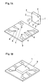
- a plurality of bumps 2 are formed on a semiconductor device 1 to project from the surface thereof.
- a plurality of electrode terminals 5 corresponding to the bumps 2 on the semiconductor devices 1 are formed on the substrate 3 to which the semiconductor device 1 is to be packaged (Fig. 1A).
- the electrode terminal 5 may, for example, be formed in the following manner. First, a recess is formed at an area of the substrate 3 at which the electrode terminal 5 is to be formed. The recess is large enough to receive at least the top (bottom in the drawing) of the bump 2 formed on the semiconductor device 1. The recess is selectively plated to form the electrode terminal 5.
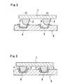
- the electrode terminal 5 thus formed has the recess 4 for receiving at least the top of the bump 2 on the surface thereof (See Fig. 2 and 3). It is preferable that a center of the electrode terminal 5 coincides to a deepest (lowest) position of the recess 4.
- the bump 2 on the semiconductor device 1 is positioned to the electrode terminal 5 on the substrate by a positioning machine (not shown). This positioning may be coarse to assure that a portion of the bump 2 abuts the metal layer 5 as shown in Fig. 2.
- the bump 2 is guided along the surface of the recess 4 of the electrode terminal 5 as shown in Fig. 3 by lightly pushing the semiconductor device 1 to the substrate 3 after the positioning so that the bump 2 is automatically moved to the center of the electrode terminal 5 and precisely positioned to the electrode terminal 5. After such precise positioning, the substrate 3 is heated to melt the bump 2 so that the bump 2 is connected to the electrode terminal 5.
- a surface tension of the molten bump material functions to minimize a surface area of the bump material between the electrode pad (not shown) on the semiconductor device 1 at which the bump 2 is formed and the electrode terminal 5 on the substrate 3.
- the surface tension functions to minimize the total positional error between the electrode pad on the semiconductor device 1 at which the bump 2 is formed and the electrode terminal 5 on the substrate 3 and the semiconductor device 1 is guided to a position at which the surface tensions of the respective bump materials balance. By this surface tension, more precise positioning is automatically attained. Where spare solder is provided to the electrode terminal and it is reflown, the surface tension of the molten solder functions in the same manner.
- insulative bonding agent which contracts when it cures may be filled into a gap between the semiconductor device 1 and the substrate 3 and the bump 2 may be pushed to the electrode terminal 5 by a curing contraction force of the bonding agent to electrically connect the bump 2 to the electrode terminal 5.
- a plurality of bumps 2 are formed on a semiconductor device 1 to project from the surface thereof.
- a plurality of recesses 4 corresponding to the bumps on the semiconductor device 1 are formed on the substrate 3 on which the semiconductor device 1 is to be packaged, and the electrode terminals 5 are formed at the centers of the recesses 4 (See Figs. 4 and 5).
- Each of the recesses 4 has a dimension which is large enough to receive at least a top (bottom in the drawing) of the bump 2 formed on the semiconductor device 1, and a depth of the recess gradually increases as it goes from the periphery to the center at which the electrode terminal 5 is formed.
- the depth of the recess 4 may gradually increase continuously from the periphery to the center.
- the electrode 5 may, for example, be formed by selectively plating at the center of the recess 4.
- the bump 2 on the semiconductor device 1 is positioned to the electrode terminal on the substrate 3 by a positioning machine (not shown). This positioning may be coarse positioning which assures that the top of the bump 2 does not swell out of the recess 4 as shown in Fig. 4.
- a size of the bump 2 formed on the semiconductor device 1 was 80 ⁇ m in diameter and approximately 30 ⁇ m in height, and a size of the electrode terminal 5 on the substrate 3 was 100 ⁇ m in diameter.
- the outer diameter of the recess 4 was substantially equal to the diameter of the electrode terminal and the depth of the recess 4 was approximately 10 ⁇ m.
- the semiconductor device 1 was packaged on the substrate 3. In this case, a positioning precision required for a positioning machine in order to maintain a positioned error between the bump 2 and the electrode terminal 5 after the packaging within + 10 ⁇ m was + 50 ⁇ m.
- the same semiconductor device as that of the above example was packaged on a prior art substrate having a flat electrode terminal of the same dimension as that of the above example.
- the precision required for the positioning machine was +/- 10 ⁇ m. The result is shown below.
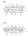
- a plurality of bump electrodes are formed on a semiconductor device 1 to project therefrom.
- a height of some bump electrode 2a is higher than that of the remaining bump electrode 2b so that the bump electrode 2a projects more largely from the surface of the semiconductor device 1 than the remaining bump electrode 2b.
- a plurality of electrode terminals 5a and 5b are formed on a packaging substrate 3 on which the semiconductor device 1 is packaged, corresponding to the bump electrodes 2a and 2b on the semiconductor device 1.
- a recess 4 for receiving at least a top of the bump electrode 2a is formed on a surface of the electrode terminal 5a which corresponds to the bump electrode 2a (See Figs. 6 and 7).
- a depth of the recess 4 gradually increases as it goes from a periphery to a center and it is deepest at the center.
- the electrode terminal 5a having such recess 4 may, for example, be formed in the following manner. First, a recess is formed at an area of the packaging substrate 3 at which the electrode terminal 5a is to be formed. The recess is large enough to receive at least a top (bottom in the drawing) of the bump 2 formed on the semiconductor device 1. The recess is selectively metal-plated or vacuum-deposited to form the electrode terminal 5a. The electrode terminal 5a thus formed has the recess 4 for receiving at least the top of the bump electrode 2a, formed there on.
- the bump 2 on the semiconductor device 1 is positioned to the electrode terminal 5 on the substrate by a positioning machine (not shown). This positioning may be coarse to assure that a portion of the bump 2 abuts the metal layer 5a as shown in Fig. 6. Because if the top of the bump 2 is positioned within a range of the recess 4 of the electrode terminal 5, the bump 2 is guided along the surface of the recess 4 of the electrode terminal 5 by lightly pushing the semiconductor device 1 to the substrate 3 after the positioning and it is automatically moved toward the center of the recess 4.
- the bump electrode 2a is positioned to the center of the electrode terminal 5a and the other bump electrode 2b abuts against the corresponding electrode terminal 5a. And the first abutted bump electrode 2a slides on the packaging substrate 3 while it contacts thereto. Accordingly, the bump electrode 2a contacts to the wiring pattern formed on the packaging substrate 3 including the electrode terminals 5a and 5b, and the wiring pattern is damaged by the contact. In order to reduce the damage which the wiring pattern suffers from the contact to the bump electrode, in accordance with the present invention, some bump electrode 2a projects more largely from the surface of the semiconductor device 1 than the other bump electrode 2b.
- the number of bump electrodes which contact to the wiring pattern before the positioning is completed can be reduced, and the damage which the bump electrode and the wiring pattern suffer from the contact can be reduced. Accordingly, a total reliability of the bump electrodes 2a and 2b and the electrode terminals 5a and 5b is improved and a yield of packaging is improved.
- the bump electrode 2a which is formed higher than the other bump electrode 2b from a low bump electrode density area such as a corner of the semiconductor device 1 as shown in Fig. 8, a frequency of contact of the bump electrode 2a to the wiring pattern formed on the packaging substrate 3 can be further reduced.
- the recess 4 for receiving the top of the bump electrode 2a is formed only in the electrode terminal 5a formed on the packaging substrate 3 correspondingly to the bump electrode 2a.
- the recess 4 By forming the recess 4 only in the limited electrode terminals, the number of electrode terminals having the recesses formed therein can be reduced.
- the bump electrode 2a and the electrode terminal 5a which contribute to the positioning as a bump electrode and an electrode terminal for exclusively positioning use which are not connected to the electronic circuit formed on the semiconductor device 3
- the other bump electrode 2b and electrode terminal 5b which are connected to the electronic circuit of the semiconductor device and contribute to the exchange of electrical signals with the electronic circuit do not contact to each other until the positioning is completed and the damage due to the contact is prevented.
- a possible area of break due to the formation of steps disappears from the exchange of the electrical signals with the electronic circuit.
- the packaging substrate 3 After the positioning of the semiconductor device 1 to the packaging substrate 3, the packaging substrate 3 is heated, spare solder (not shown) applied to the electrode terminals 5a and 5b is reflown and the bump, electrodes 2a and 2b and the corresponding electrode terminals 5a and 5b are interconnected.
- a surface tension of the reflown spare solder acts to gaps between the bump electrodes 2a and 2b and the electrode terminals 5a and 5b and more precise positioning is automatically attained by the action of the surface tension. Even if the spare solder is not applied, a same effect may be attained by melting the bump electrodes 2a and 2b by heating them.
- the recess 4 for receiving the top of the bump electrode 2a is formed in the electrode terminal 5a on the packaging substrate.
- a recess for receiving the top of the bump electrode 2a may be formed on the surface of the packaging substrate 3 and an electrode terminal which is formed correspondingly to the bump electrode 2a may be arranged at the center of the recess to attain similar operation and effect.
- a high precision and expensive positioning machine used in the prior art is not required and a relatively inexpensive positioning machine can be used.
- the positioning by the positioning machine may be coarse, the positioning time required for the positioning by the positioning machine is shorter than that in the prior art which required the precise positioning by the positioning machine. Accordingly, the time and cost for the packaging can be reduced.
- the damage of the electrode terminals and the bump electrodes which are formed on the packaging substrate and connected to the electronic circuit of the semiconductor device is reduced, the reliability of the electrode terminal and the bump electrodes is improved and the semiconductor device can be packaged on the packaging substrate with high reliability and high yield.
Applications Claiming Priority (6)
| Application Number | Priority Date | Filing Date | Title |
|---|---|---|---|
| JP2013413A JPH03218035A (ja) | 1990-01-23 | 1990-01-23 | 半導体素子実装用基板 |
| JP13413/90 | 1990-01-23 | ||
| JP13412/90 | 1990-01-23 | ||
| JP2013417A JPH03218039A (ja) | 1990-01-23 | 1990-01-23 | 半導体素子の実装方法 |
| JP2013412A JPH03218034A (ja) | 1990-01-23 | 1990-01-23 | 半導体素子実装用基板 |
| JP13417/90 | 1990-01-23 |
Publications (2)
| Publication Number | Publication Date |
|---|---|
| EP0439134A2 true EP0439134A2 (de) | 1991-07-31 |
| EP0439134A3 EP0439134A3 (de) | 1994-02-02 |
Family
ID=27280241
Family Applications (1)
| Application Number | Title | Priority Date | Filing Date |
|---|---|---|---|
| EP91100818A Withdrawn EP0439134A2 (de) | 1990-01-23 | 1991-01-23 | Substrat zur Verpackung einer Halbleitervorrichtung, Verpackungsstruktur und -methode |
Country Status (5)
| Country | Link |
|---|---|
| US (1) | US5214308A (de) |
| EP (1) | EP0439134A2 (de) |
| KR (1) | KR950001365B1 (de) |
| AU (1) | AU645283B2 (de) |
| CA (1) | CA2034703A1 (de) |
Cited By (11)
| Publication number | Priority date | Publication date | Assignee | Title |
|---|---|---|---|---|
| US5329423A (en) * | 1993-04-13 | 1994-07-12 | Scholz Kenneth D | Compressive bump-and-socket interconnection scheme for integrated circuits |
| EP0637070A1 (de) * | 1993-07-28 | 1995-02-01 | The Whitaker Corporation | Von der Peripherie-unabhängiges präzises Positionsglied für einen Halbleiterchip und Herstellungsverfahren dafür |
| EP0663140A1 (de) * | 1992-10-02 | 1995-07-19 | Irvine Sensors Corporation | Herstellung von dichten parallelen loethoeckerverbindungen |
| WO1998027596A1 (en) * | 1996-12-19 | 1998-06-25 | Telefonaktiebolaget Lm Ericsson (Publ) | High density electrical connectors |
| WO1998027587A1 (en) * | 1996-12-19 | 1998-06-25 | Telefonaktiebolaget Lm Ericsson (Publ) | A packaging structure for integrated circuits |
| SG80587A1 (en) * | 1998-03-25 | 2001-05-22 | Texas Instr Singapore Pte Ltd | Semiconductor device testing and burn-in methodology |
| DE10240461A1 (de) * | 2002-08-29 | 2004-03-11 | Infineon Technologies Ag | Universelles Gehäuse für ein elektronisches Bauteil mit Halbleiterchip und Verfahren zu seiner Herstellung |
| EP1431242A2 (de) * | 2002-11-14 | 2004-06-23 | Samsung Electronics Co., Ltd. | Verbindungsstruktur und Verbindungsverfahren für Flip-chip und Mems |
| WO2005001933A2 (de) * | 2003-06-28 | 2005-01-06 | Infineon Technologies Ag | Multichip-halbleiterbaustein und verfahren zu seiner herstellung |
| EP2054933A1 (de) * | 2006-07-31 | 2009-05-06 | Intellectual Ventures Fund 27 LLC | Substrat und prozess für eine halbleiter-flipchip-kapselung |
| CN103579012A (zh) * | 2013-10-24 | 2014-02-12 | 天水华天科技股份有限公司 | 带焊球面阵列四面扁平无引脚封装件生产方法 |
Families Citing this family (224)
| Publication number | Priority date | Publication date | Assignee | Title |
|---|---|---|---|---|
| JP2673993B2 (ja) * | 1990-07-02 | 1997-11-05 | 日本無線株式会社 | 表面弾性波装置 |
| US5656507A (en) * | 1992-01-28 | 1997-08-12 | British Telecommunications Public Limited Company | Process for self-aligning circuit components brought into abutment by surface tension of a molten material and bonding under tension |
| JP3215424B2 (ja) * | 1992-03-24 | 2001-10-09 | ユニシス・コーポレイション | 微細自己整合特性を有する集積回路モジュール |
| US5411400A (en) * | 1992-09-28 | 1995-05-02 | Motorola, Inc. | Interconnect system for a semiconductor chip and a substrate |
| US5435482A (en) * | 1994-02-04 | 1995-07-25 | Lsi Logic Corporation | Integrated circuit having a coplanar solder ball contact array |
| US5578869A (en) * | 1994-03-29 | 1996-11-26 | Olin Corporation | Components for housing an integrated circuit device |
| US5712192A (en) * | 1994-04-26 | 1998-01-27 | International Business Machines Corporation | Process for connecting an electrical device to a circuit substrate |
| US5523628A (en) * | 1994-08-05 | 1996-06-04 | Hughes Aircraft Company | Apparatus and method for protecting metal bumped integrated circuit chips during processing and for providing mechanical support to interconnected chips |
| FR2727227B1 (fr) * | 1994-11-17 | 1996-12-20 | Schlumberger Ind Sa | Dispositif de securite actif a memoire electronique |
| US6826827B1 (en) * | 1994-12-29 | 2004-12-07 | Tessera, Inc. | Forming conductive posts by selective removal of conductive material |
| US5573171A (en) * | 1995-02-16 | 1996-11-12 | Trw Inc. | Method of thin film patterning by reflow |
| KR100273499B1 (ko) * | 1995-05-22 | 2001-01-15 | 우찌가사끼 이사오 | 배선기판에전기접속된반도체칩을갖는반도체장치 |
| US20020004320A1 (en) * | 1995-05-26 | 2002-01-10 | David V. Pedersen | Attaratus for socketably receiving interconnection elements of an electronic component |
| US5598036A (en) * | 1995-06-15 | 1997-01-28 | Industrial Technology Research Institute | Ball grid array having reduced mechanical stress |
| JP3310499B2 (ja) * | 1995-08-01 | 2002-08-05 | 富士通株式会社 | 半導体装置 |
| US5810609A (en) * | 1995-08-28 | 1998-09-22 | Tessera, Inc. | Socket for engaging bump leads on a microelectronic device and methods therefor |
| DE59611449D1 (de) * | 1995-09-08 | 2007-12-20 | Fraunhofer Ges Forschung | Verfahren und vorrichtung zum testen eines chips |
| US5795194A (en) | 1995-09-29 | 1998-08-18 | Berg Technology, Inc. | Electrical connector with V-grooves |
| US6376921B1 (en) | 1995-11-08 | 2002-04-23 | Fujitsu Limited | Semiconductor device, method for fabricating the semiconductor device, lead frame and method for producing the lead frame |
| US6159770A (en) * | 1995-11-08 | 2000-12-12 | Fujitsu Limited | Method and apparatus for fabricating semiconductor device |
| US6329711B1 (en) | 1995-11-08 | 2001-12-11 | Fujitsu Limited | Semiconductor device and mounting structure |
| US6072239A (en) * | 1995-11-08 | 2000-06-06 | Fujitsu Limited | Device having resin package with projections |
| KR100438256B1 (ko) * | 1995-12-18 | 2004-08-25 | 마츠시타 덴끼 산교 가부시키가이샤 | 반도체장치 및 그 제조방법 |
| US5660321A (en) * | 1996-03-29 | 1997-08-26 | Intel Corporation | Method for controlling solder bump height and volume for substrates containing both pad-on and pad-off via contacts |
| US5726502A (en) * | 1996-04-26 | 1998-03-10 | Motorola, Inc. | Bumped semiconductor device with alignment features and method for making the same |
| JP2830852B2 (ja) * | 1996-08-08 | 1998-12-02 | 松下電器産業株式会社 | 電子部品実装方法 |
| SE9604678L (sv) | 1996-12-19 | 1998-06-20 | Ericsson Telefon Ab L M | Bulor i spår för elastisk lokalisering |
| US6406989B1 (en) * | 1997-02-21 | 2002-06-18 | Nec Corporation | Method of fabricating semiconductor device with bump electrodes |
| JPH10233413A (ja) * | 1997-02-21 | 1998-09-02 | Nec Kansai Ltd | 半導体装置およびその製造方法並びに配線基板 |
| US6040618A (en) * | 1997-03-06 | 2000-03-21 | Micron Technology, Inc. | Multi-chip module employing a carrier substrate with micromachined alignment structures and method of forming |
| US6246548B1 (en) | 1997-03-24 | 2001-06-12 | Maxtor Corporation | Mechanically formed standoffs in a circuit interconnect |
| US5929521A (en) * | 1997-03-26 | 1999-07-27 | Micron Technology, Inc. | Projected contact structure for bumped semiconductor device and resulting articles and assemblies |
| JPH1174312A (ja) * | 1997-08-28 | 1999-03-16 | Mitsubishi Electric Corp | 半導体装置およびはんだバンプの形成方法 |
| US6096576A (en) | 1997-09-02 | 2000-08-01 | Silicon Light Machines | Method of producing an electrical interface to an integrated circuit device having high density I/O count |
| KR100266637B1 (ko) * | 1997-11-15 | 2000-09-15 | 김영환 | 적층형볼그리드어레이반도체패키지및그의제조방법 |
| US6046910A (en) * | 1998-03-18 | 2000-04-04 | Motorola, Inc. | Microelectronic assembly having slidable contacts and method for manufacturing the assembly |
| US6040630A (en) | 1998-04-13 | 2000-03-21 | Harris Corporation | Integrated circuit package for flip chip with alignment preform feature and method of forming same |
| US6172414B1 (en) * | 1998-04-28 | 2001-01-09 | Trw Inc. | Apparatus and method for snap-on thermo-compression bonding |
| US6337509B2 (en) * | 1998-07-16 | 2002-01-08 | International Business Machines Corporation | Fixture for attaching a conformal chip carrier to a flip chip |
| US6303986B1 (en) | 1998-07-29 | 2001-10-16 | Silicon Light Machines | Method of and apparatus for sealing an hermetic lid to a semiconductor die |
| JP3846611B2 (ja) * | 1998-09-25 | 2006-11-15 | ソニー株式会社 | 実装用半導体部品、実装構造及び実装方法 |
| US6887723B1 (en) * | 1998-12-04 | 2005-05-03 | Formfactor, Inc. | Method for processing an integrated circuit including placing dice into a carrier and testing |
| US6927491B1 (en) * | 1998-12-04 | 2005-08-09 | Nec Corporation | Back electrode type electronic part and electronic assembly with the same mounted on printed circuit board |
| JP2000195984A (ja) * | 1998-12-24 | 2000-07-14 | Shinko Electric Ind Co Ltd | 半導体装置用キャリア基板及びその製造方法及び半導体装置及びその製造方法 |
| US6456099B1 (en) * | 1998-12-31 | 2002-09-24 | Formfactor, Inc. | Special contact points for accessing internal circuitry of an integrated circuit |
| US6965166B2 (en) * | 1999-02-24 | 2005-11-15 | Rohm Co., Ltd. | Semiconductor device of chip-on-chip structure |
| JP3399518B2 (ja) * | 1999-03-03 | 2003-04-21 | インターナショナル・ビジネス・マシーンズ・コーポレーション | 半導体構造およびその製造方法 |
| JP3726998B2 (ja) * | 1999-04-01 | 2005-12-14 | 株式会社村田製作所 | 表面波装置 |
| JP4362163B2 (ja) * | 1999-04-06 | 2009-11-11 | 富士通マイクロエレクトロニクス株式会社 | 半導体装置の製造方法 |
| US6517359B1 (en) | 1999-05-21 | 2003-02-11 | Agilent Technologies, Inc. | System and method for mating electrical connections |
| US6313999B1 (en) | 1999-06-10 | 2001-11-06 | Agere Systems Optoelectronics Guardian Corp. | Self alignment device for ball grid array devices |
| US6077766A (en) * | 1999-06-25 | 2000-06-20 | International Business Machines Corporation | Variable thickness pads on a substrate surface |
| US6352881B1 (en) | 1999-07-22 | 2002-03-05 | National Semiconductor Corporation | Method and apparatus for forming an underfill adhesive layer |
| US6805278B1 (en) * | 1999-10-19 | 2004-10-19 | Fci America Technology, Inc. | Self-centering connector with hold down |
| TW531948B (en) | 1999-10-19 | 2003-05-11 | Fci Sa | Electrical connector with strain relief |
| JP4464527B2 (ja) * | 1999-12-24 | 2010-05-19 | 大日本印刷株式会社 | 半導体搭載用部材およびその製造方法 |
| EP1122567A1 (de) * | 2000-02-02 | 2001-08-08 | Corning Incorporated | Passive Ausrichtung unter Verwendung von geneigter Sockelwand |
| US6580165B1 (en) * | 2000-11-16 | 2003-06-17 | Fairchild Semiconductor Corporation | Flip chip with solder pre-plated leadframe including locating holes |
| US6707591B2 (en) | 2001-04-10 | 2004-03-16 | Silicon Light Machines | Angled illumination for a single order light modulator based projection system |
| US6782205B2 (en) | 2001-06-25 | 2004-08-24 | Silicon Light Machines | Method and apparatus for dynamic equalization in wavelength division multiplexing |
| US6747781B2 (en) | 2001-06-25 | 2004-06-08 | Silicon Light Machines, Inc. | Method, apparatus, and diffuser for reducing laser speckle |
| US6829092B2 (en) | 2001-08-15 | 2004-12-07 | Silicon Light Machines, Inc. | Blazed grating light valve |
| JP2003188507A (ja) * | 2001-12-18 | 2003-07-04 | Mitsubishi Electric Corp | 半導体集積回路およびこれを実装するためのプリント配線板 |
| US6800238B1 (en) | 2002-01-15 | 2004-10-05 | Silicon Light Machines, Inc. | Method for domain patterning in low coercive field ferroelectrics |
| US6767751B2 (en) | 2002-05-28 | 2004-07-27 | Silicon Light Machines, Inc. | Integrated driver process flow |
| US6728023B1 (en) | 2002-05-28 | 2004-04-27 | Silicon Light Machines | Optical device arrays with optimized image resolution |
| DE10223738B4 (de) * | 2002-05-28 | 2007-09-27 | Qimonda Ag | Verfahren zur Verbindung integrierter Schaltungen |
| US6822797B1 (en) | 2002-05-31 | 2004-11-23 | Silicon Light Machines, Inc. | Light modulator structure for producing high-contrast operation using zero-order light |
| US6829258B1 (en) | 2002-06-26 | 2004-12-07 | Silicon Light Machines, Inc. | Rapidly tunable external cavity laser |
| US6813059B2 (en) | 2002-06-28 | 2004-11-02 | Silicon Light Machines, Inc. | Reduced formation of asperities in contact micro-structures |
| US6714337B1 (en) | 2002-06-28 | 2004-03-30 | Silicon Light Machines | Method and device for modulating a light beam and having an improved gamma response |
| US7423337B1 (en) | 2002-08-19 | 2008-09-09 | National Semiconductor Corporation | Integrated circuit device package having a support coating for improved reliability during temperature cycling |
| US6801354B1 (en) | 2002-08-20 | 2004-10-05 | Silicon Light Machines, Inc. | 2-D diffraction grating for substantially eliminating polarization dependent losses |
| JP3722137B2 (ja) * | 2002-08-21 | 2005-11-30 | セイコーエプソン株式会社 | 半導体装置の実装方法、半導体装置の実装構造、電気光学装置、電気光学装置の製造方法及び電子機器 |
| US6917892B2 (en) * | 2002-09-16 | 2005-07-12 | Anritsu Company | Single port single connection VNA calibration apparatus |
| US6791845B2 (en) * | 2002-09-26 | 2004-09-14 | Fci Americas Technology, Inc. | Surface mounted electrical components |
| US6712480B1 (en) | 2002-09-27 | 2004-03-30 | Silicon Light Machines | Controlled curvature of stressed micro-structures |
| US6906598B2 (en) * | 2002-12-31 | 2005-06-14 | Mcnc | Three dimensional multimode and optical coupling devices |
| US20040129453A1 (en) * | 2003-01-07 | 2004-07-08 | Boggs David W. | Electronic substrate with direct inner layer component interconnection |
| US6900389B2 (en) * | 2003-01-10 | 2005-05-31 | Fci Americas Technology, Inc. | Cover for ball-grid array connector |
| US7253510B2 (en) | 2003-01-16 | 2007-08-07 | International Business Machines Corporation | Ball grid array package construction with raised solder ball pads |
| US20040147169A1 (en) | 2003-01-28 | 2004-07-29 | Allison Jeffrey W. | Power connector with safety feature |
| US7301222B1 (en) | 2003-02-12 | 2007-11-27 | National Semiconductor Corporation | Apparatus for forming a pre-applied underfill adhesive layer for semiconductor wafer level chip-scale packages |
| US6806997B1 (en) | 2003-02-28 | 2004-10-19 | Silicon Light Machines, Inc. | Patterned diffractive light modulator ribbon for PDL reduction |
| US6829077B1 (en) | 2003-02-28 | 2004-12-07 | Silicon Light Machines, Inc. | Diffractive light modulator with dynamically rotatable diffraction plane |
| US7462936B2 (en) * | 2003-10-06 | 2008-12-09 | Tessera, Inc. | Formation of circuitry with modification of feature height |
| US7495179B2 (en) * | 2003-10-06 | 2009-02-24 | Tessera, Inc. | Components with posts and pads |
| US8641913B2 (en) * | 2003-10-06 | 2014-02-04 | Tessera, Inc. | Fine pitch microcontacts and method for forming thereof |
| US7084500B2 (en) * | 2003-10-29 | 2006-08-01 | Texas Instruments Incorporated | Semiconductor circuit with multiple contact sizes |
| US7425759B1 (en) * | 2003-11-20 | 2008-09-16 | Bridge Semiconductor Corporation | Semiconductor chip assembly with bumped terminal and filler |
| US8207604B2 (en) * | 2003-12-30 | 2012-06-26 | Tessera, Inc. | Microelectronic package comprising offset conductive posts on compliant layer |
| US7709968B2 (en) * | 2003-12-30 | 2010-05-04 | Tessera, Inc. | Micro pin grid array with pin motion isolation |
| US7176043B2 (en) * | 2003-12-30 | 2007-02-13 | Tessera, Inc. | Microelectronic packages and methods therefor |
| EP1702389B1 (de) | 2003-12-31 | 2020-12-09 | Amphenol FCI Asia Pte. Ltd. | Elektrische leistungskontakte und verbinder damit |
| US7458839B2 (en) * | 2006-02-21 | 2008-12-02 | Fci Americas Technology, Inc. | Electrical connectors having power contacts with alignment and/or restraining features |
| US7303941B1 (en) | 2004-03-12 | 2007-12-04 | Cisco Technology, Inc. | Methods and apparatus for providing a power signal to an area array package |
| US20050208749A1 (en) * | 2004-03-17 | 2005-09-22 | Beckman Michael W | Methods for forming electrical connections and resulting devices |
| US7282375B1 (en) | 2004-04-14 | 2007-10-16 | National Semiconductor Corporation | Wafer level package design that facilitates trimming and testing |
| US7109583B2 (en) * | 2004-05-06 | 2006-09-19 | Endwave Corporation | Mounting with auxiliary bumps |
| WO2006004671A2 (en) * | 2004-06-25 | 2006-01-12 | Tessera, Inc. | Microelectronic package structure with spherical contact pins |
| US7453157B2 (en) * | 2004-06-25 | 2008-11-18 | Tessera, Inc. | Microelectronic packages and methods therefor |
| EP1765724B1 (de) * | 2004-07-08 | 2013-12-18 | International Business Machines Corporation | Verfahren zur verbesserung der ausrichtungsgenauigkeit von teilen in mems |
| US8525314B2 (en) * | 2004-11-03 | 2013-09-03 | Tessera, Inc. | Stacked packaging improvements |
| TWI237364B (en) * | 2004-12-14 | 2005-08-01 | Advanced Semiconductor Eng | Flip chip package with anti-floating mechanism |
| US7476108B2 (en) | 2004-12-22 | 2009-01-13 | Fci Americas Technology, Inc. | Electrical power connectors with cooling features |
| US7384289B2 (en) * | 2005-01-31 | 2008-06-10 | Fci Americas Technology, Inc. | Surface-mount connector |
| US7939934B2 (en) * | 2005-03-16 | 2011-05-10 | Tessera, Inc. | Microelectronic packages and methods therefor |
| US7364945B2 (en) * | 2005-03-31 | 2008-04-29 | Stats Chippac Ltd. | Method of mounting an integrated circuit package in an encapsulant cavity |
| US7303427B2 (en) * | 2005-04-05 | 2007-12-04 | Fci Americas Technology, Inc. | Electrical connector with air-circulation features |
| US7354800B2 (en) | 2005-04-29 | 2008-04-08 | Stats Chippac Ltd. | Method of fabricating a stacked integrated circuit package system |
| US8957511B2 (en) * | 2005-08-22 | 2015-02-17 | Madhukar B. Vora | Apparatus and methods for high-density chip connectivity |
| US7745301B2 (en) * | 2005-08-22 | 2010-06-29 | Terapede, Llc | Methods and apparatus for high-density chip connectivity |
| US20070045812A1 (en) * | 2005-08-31 | 2007-03-01 | Micron Technology, Inc. | Microfeature assemblies including interconnect structures and methods for forming such interconnect structures |
| US8067267B2 (en) * | 2005-12-23 | 2011-11-29 | Tessera, Inc. | Microelectronic assemblies having very fine pitch stacking |
| US8058101B2 (en) | 2005-12-23 | 2011-11-15 | Tessera, Inc. | Microelectronic packages and methods therefor |
| US7768125B2 (en) * | 2006-01-04 | 2010-08-03 | Stats Chippac Ltd. | Multi-chip package system |
| US7456088B2 (en) | 2006-01-04 | 2008-11-25 | Stats Chippac Ltd. | Integrated circuit package system including stacked die |
| US7750482B2 (en) * | 2006-02-09 | 2010-07-06 | Stats Chippac Ltd. | Integrated circuit package system including zero fillet resin |
| US8704349B2 (en) * | 2006-02-14 | 2014-04-22 | Stats Chippac Ltd. | Integrated circuit package system with exposed interconnects |
| US7385299B2 (en) * | 2006-02-25 | 2008-06-10 | Stats Chippac Ltd. | Stackable integrated circuit package system with multiple interconnect interface |
| JP2007266111A (ja) * | 2006-03-27 | 2007-10-11 | Sharp Corp | 半導体装置、それを用いた積層型半導体装置、ベース基板、および半導体装置の製造方法 |
| US7425145B2 (en) * | 2006-05-26 | 2008-09-16 | Fci Americas Technology, Inc. | Connectors and contacts for transmitting electrical power |
| US7726982B2 (en) * | 2006-06-15 | 2010-06-01 | Fci Americas Technology, Inc. | Electrical connectors with air-circulation features |
| US7545029B2 (en) * | 2006-08-18 | 2009-06-09 | Tessera, Inc. | Stack microelectronic assemblies |
| US20080150101A1 (en) * | 2006-12-20 | 2008-06-26 | Tessera, Inc. | Microelectronic packages having improved input/output connections and methods therefor |
| US7641500B2 (en) | 2007-04-04 | 2010-01-05 | Fci Americas Technology, Inc. | Power cable connector system |
| JP5350604B2 (ja) * | 2007-05-16 | 2013-11-27 | スパンション エルエルシー | 半導体装置及びその製造方法 |
| US7905731B2 (en) | 2007-05-21 | 2011-03-15 | Fci Americas Technology, Inc. | Electrical connector with stress-distribution features |
| US7564130B1 (en) * | 2007-07-06 | 2009-07-21 | National Semiconductor Corporation | Power micro surface-mount device package |
| KR101388538B1 (ko) | 2007-09-28 | 2014-04-23 | 테세라, 인코포레이티드 | 이중 포스트를 사용하여 플립칩 상호연결한 마이크로전자 어셈블리 |
| US7762857B2 (en) * | 2007-10-01 | 2010-07-27 | Fci Americas Technology, Inc. | Power connectors with contact-retention features |
| US8004070B1 (en) * | 2008-04-29 | 2011-08-23 | Wei Chen | Wire-free chip module and method |
| US8062051B2 (en) | 2008-07-29 | 2011-11-22 | Fci Americas Technology Llc | Electrical communication system having latching and strain relief features |
| US20100044860A1 (en) * | 2008-08-21 | 2010-02-25 | Tessera Interconnect Materials, Inc. | Microelectronic substrate or element having conductive pads and metal posts joined thereto using bond layer |
| USD640637S1 (en) | 2009-01-16 | 2011-06-28 | Fci Americas Technology Llc | Vertical electrical connector |
| USD664096S1 (en) | 2009-01-16 | 2012-07-24 | Fci Americas Technology Llc | Vertical electrical connector |
| USD610548S1 (en) | 2009-01-16 | 2010-02-23 | Fci Americas Technology, Inc. | Right-angle electrical connector |
| USD608293S1 (en) | 2009-01-16 | 2010-01-19 | Fci Americas Technology, Inc. | Vertical electrical connector |
| USD606497S1 (en) | 2009-01-16 | 2009-12-22 | Fci Americas Technology, Inc. | Vertical electrical connector |
| US8323049B2 (en) | 2009-01-30 | 2012-12-04 | Fci Americas Technology Llc | Electrical connector having power contacts |
| USD619099S1 (en) | 2009-01-30 | 2010-07-06 | Fci Americas Technology, Inc. | Electrical connector |
| US8366485B2 (en) | 2009-03-19 | 2013-02-05 | Fci Americas Technology Llc | Electrical connector having ribbed ground plate |
| USD618181S1 (en) | 2009-04-03 | 2010-06-22 | Fci Americas Technology, Inc. | Asymmetrical electrical connector |
| USD618180S1 (en) | 2009-04-03 | 2010-06-22 | Fci Americas Technology, Inc. | Asymmetrical electrical connector |
| US8603862B2 (en) * | 2010-05-14 | 2013-12-10 | International Business Machines Corporation | Precise-aligned lock-and-key bonding structures |
| US8330272B2 (en) | 2010-07-08 | 2012-12-11 | Tessera, Inc. | Microelectronic packages with dual or multiple-etched flip-chip connectors |
| US8482111B2 (en) | 2010-07-19 | 2013-07-09 | Tessera, Inc. | Stackable molded microelectronic packages |
| US9159708B2 (en) | 2010-07-19 | 2015-10-13 | Tessera, Inc. | Stackable molded microelectronic packages with area array unit connectors |
| US8580607B2 (en) | 2010-07-27 | 2013-11-12 | Tessera, Inc. | Microelectronic packages with nanoparticle joining |
| KR101075241B1 (ko) | 2010-11-15 | 2011-11-01 | 테세라, 인코포레이티드 | 유전체 부재에 단자를 구비하는 마이크로전자 패키지 |
| US8994048B2 (en) * | 2010-12-09 | 2015-03-31 | Stats Chippac, Ltd. | Semiconductor device and method of forming recesses in substrate for same size or different sized die with vertical integration |
| US8853558B2 (en) | 2010-12-10 | 2014-10-07 | Tessera, Inc. | Interconnect structure |
| US20120146206A1 (en) | 2010-12-13 | 2012-06-14 | Tessera Research Llc | Pin attachment |
| US9137903B2 (en) | 2010-12-21 | 2015-09-15 | Tessera, Inc. | Semiconductor chip assembly and method for making same |
| KR101128063B1 (ko) | 2011-05-03 | 2012-04-23 | 테세라, 인코포레이티드 | 캡슐화 층의 표면에 와이어 본드를 구비하는 패키지 적층형 어셈블리 |
| US8618659B2 (en) | 2011-05-03 | 2013-12-31 | Tessera, Inc. | Package-on-package assembly with wire bonds to encapsulation surface |
| US8872318B2 (en) | 2011-08-24 | 2014-10-28 | Tessera, Inc. | Through interposer wire bond using low CTE interposer with coarse slot apertures |
| US8404520B1 (en) | 2011-10-17 | 2013-03-26 | Invensas Corporation | Package-on-package assembly with wire bond vias |
| US20130119532A1 (en) * | 2011-11-11 | 2013-05-16 | Taiwan Semiconductor Manufacturing Company, Ltd. | Bumps for Chip Scale Packaging |
| EP2624034A1 (de) | 2012-01-31 | 2013-08-07 | Fci | Abbaubare optische Kupplungsvorrichtung |
| US8946757B2 (en) | 2012-02-17 | 2015-02-03 | Invensas Corporation | Heat spreading substrate with embedded interconnects |
| US8372741B1 (en) | 2012-02-24 | 2013-02-12 | Invensas Corporation | Method for package-on-package assembly with wire bonds to encapsulation surface |
| US9349706B2 (en) | 2012-02-24 | 2016-05-24 | Invensas Corporation | Method for package-on-package assembly with wire bonds to encapsulation surface |
| US9257778B2 (en) | 2012-04-13 | 2016-02-09 | Fci Americas Technology | High speed electrical connector |
| US8944831B2 (en) | 2012-04-13 | 2015-02-03 | Fci Americas Technology Llc | Electrical connector having ribbed ground plate with engagement members |
| USD727852S1 (en) | 2012-04-13 | 2015-04-28 | Fci Americas Technology Llc | Ground shield for a right angle electrical connector |
| USD718253S1 (en) | 2012-04-13 | 2014-11-25 | Fci Americas Technology Llc | Electrical cable connector |
| USD727268S1 (en) | 2012-04-13 | 2015-04-21 | Fci Americas Technology Llc | Vertical electrical connector |
| US8835228B2 (en) | 2012-05-22 | 2014-09-16 | Invensas Corporation | Substrate-less stackable package with wire-bond interconnect |
| US9543703B2 (en) | 2012-07-11 | 2017-01-10 | Fci Americas Technology Llc | Electrical connector with reduced stack height |
| USD751507S1 (en) | 2012-07-11 | 2016-03-15 | Fci Americas Technology Llc | Electrical connector |
| US9391008B2 (en) | 2012-07-31 | 2016-07-12 | Invensas Corporation | Reconstituted wafer-level package DRAM |
| US9502390B2 (en) | 2012-08-03 | 2016-11-22 | Invensas Corporation | BVA interposer |
| CN104662460B (zh) * | 2012-09-27 | 2016-11-09 | 株式会社藤仓 | 光模块 |
| US8975738B2 (en) | 2012-11-12 | 2015-03-10 | Invensas Corporation | Structure for microelectronic packaging with terminals on dielectric mass |
| US8878353B2 (en) | 2012-12-20 | 2014-11-04 | Invensas Corporation | Structure for microelectronic packaging with bond elements to encapsulation surface |
| USD745852S1 (en) | 2013-01-25 | 2015-12-22 | Fci Americas Technology Llc | Electrical connector |
| US9136254B2 (en) | 2013-02-01 | 2015-09-15 | Invensas Corporation | Microelectronic package having wire bond vias and stiffening layer |
| US9055701B2 (en) * | 2013-03-13 | 2015-06-09 | International Business Machines Corporation | Method and system for improving alignment precision of parts in MEMS |
| USD720698S1 (en) | 2013-03-15 | 2015-01-06 | Fci Americas Technology Llc | Electrical cable connector |
| US9034696B2 (en) | 2013-07-15 | 2015-05-19 | Invensas Corporation | Microelectronic assemblies having reinforcing collars on connectors extending through encapsulation |
| US9023691B2 (en) | 2013-07-15 | 2015-05-05 | Invensas Corporation | Microelectronic assemblies with stack terminals coupled by connectors extending through encapsulation |
| US8883563B1 (en) | 2013-07-15 | 2014-11-11 | Invensas Corporation | Fabrication of microelectronic assemblies having stack terminals coupled by connectors extending through encapsulation |
| US9167710B2 (en) | 2013-08-07 | 2015-10-20 | Invensas Corporation | Embedded packaging with preformed vias |
| US9685365B2 (en) | 2013-08-08 | 2017-06-20 | Invensas Corporation | Method of forming a wire bond having a free end |
| US20150076714A1 (en) | 2013-09-16 | 2015-03-19 | Invensas Corporation | Microelectronic element with bond elements to encapsulation surface |
| US9087815B2 (en) | 2013-11-12 | 2015-07-21 | Invensas Corporation | Off substrate kinking of bond wire |
| US9082753B2 (en) | 2013-11-12 | 2015-07-14 | Invensas Corporation | Severing bond wire by kinking and twisting |
| US9583456B2 (en) | 2013-11-22 | 2017-02-28 | Invensas Corporation | Multiple bond via arrays of different wire heights on a same substrate |
| US9379074B2 (en) | 2013-11-22 | 2016-06-28 | Invensas Corporation | Die stacks with one or more bond via arrays of wire bond wires and with one or more arrays of bump interconnects |
| US9263394B2 (en) | 2013-11-22 | 2016-02-16 | Invensas Corporation | Multiple bond via arrays of different wire heights on a same substrate |
| US20150153524A1 (en) * | 2013-12-03 | 2015-06-04 | Forelux Inc. | Integrated optoelectronic module |
| US9583411B2 (en) | 2014-01-17 | 2017-02-28 | Invensas Corporation | Fine pitch BVA using reconstituted wafer with area array accessible for testing |
| US20150237732A1 (en) * | 2014-02-18 | 2015-08-20 | Qualcomm Incorporated | Low-profile package with passive device |
| US9214454B2 (en) | 2014-03-31 | 2015-12-15 | Invensas Corporation | Batch process fabrication of package-on-package microelectronic assemblies |
| US10032699B1 (en) * | 2014-04-28 | 2018-07-24 | Amkor Technology, Inc. | Flip chip self-alignment features for substrate and leadframe applications |
| US10381326B2 (en) | 2014-05-28 | 2019-08-13 | Invensas Corporation | Structure and method for integrated circuits packaging with increased density |
| US9646917B2 (en) | 2014-05-29 | 2017-05-09 | Invensas Corporation | Low CTE component with wire bond interconnects |
| US9412714B2 (en) | 2014-05-30 | 2016-08-09 | Invensas Corporation | Wire bond support structure and microelectronic package including wire bonds therefrom |
| TWI567887B (zh) * | 2014-06-11 | 2017-01-21 | 矽品精密工業股份有限公司 | 封裝結構及其製法 |
| US9735084B2 (en) | 2014-12-11 | 2017-08-15 | Invensas Corporation | Bond via array for thermal conductivity |
| US9888579B2 (en) | 2015-03-05 | 2018-02-06 | Invensas Corporation | Pressing of wire bond wire tips to provide bent-over tips |
| US9502372B1 (en) | 2015-04-30 | 2016-11-22 | Invensas Corporation | Wafer-level packaging using wire bond wires in place of a redistribution layer |
| US9761554B2 (en) | 2015-05-07 | 2017-09-12 | Invensas Corporation | Ball bonding metal wire bond wires to metal pads |
| US9633971B2 (en) | 2015-07-10 | 2017-04-25 | Invensas Corporation | Structures and methods for low temperature bonding using nanoparticles |
| US10886250B2 (en) | 2015-07-10 | 2021-01-05 | Invensas Corporation | Structures and methods for low temperature bonding using nanoparticles |
| US10468363B2 (en) * | 2015-08-10 | 2019-11-05 | X-Celeprint Limited | Chiplets with connection posts |
| US11495560B2 (en) | 2015-08-10 | 2022-11-08 | X Display Company Technology Limited | Chiplets with connection posts |
| US10490528B2 (en) | 2015-10-12 | 2019-11-26 | Invensas Corporation | Embedded wire bond wires |
| US9490222B1 (en) | 2015-10-12 | 2016-11-08 | Invensas Corporation | Wire bond wires for interference shielding |
| US10332854B2 (en) | 2015-10-23 | 2019-06-25 | Invensas Corporation | Anchoring structure of fine pitch bva |
| US10181457B2 (en) | 2015-10-26 | 2019-01-15 | Invensas Corporation | Microelectronic package for wafer-level chip scale packaging with fan-out |
| US9704822B2 (en) * | 2015-11-10 | 2017-07-11 | International Business Machines Corporation | Bonding substrates using solder surface tension during solder reflow for three dimensional self-alignment of substrates |
| US10043779B2 (en) | 2015-11-17 | 2018-08-07 | Invensas Corporation | Packaged microelectronic device for a package-on-package device |
| US9659848B1 (en) | 2015-11-18 | 2017-05-23 | Invensas Corporation | Stiffened wires for offset BVA |
| US9984992B2 (en) | 2015-12-30 | 2018-05-29 | Invensas Corporation | Embedded wire bond wires for vertical integration with separate surface mount and wire bond mounting surfaces |
| US9935075B2 (en) | 2016-07-29 | 2018-04-03 | Invensas Corporation | Wire bonding method and apparatus for electromagnetic interference shielding |
| JPWO2018042846A1 (ja) * | 2016-08-30 | 2019-06-24 | 株式会社村田製作所 | 電子デバイス及び多層セラミック基板 |
| US10299368B2 (en) | 2016-12-21 | 2019-05-21 | Invensas Corporation | Surface integrated waveguides and circuit structures therefor |
| US20200045425A1 (en) * | 2018-03-07 | 2020-02-06 | USound GmbH | Method of manufacturing a mems printed circuit board module and/or sound transducer assembly |
| CN112204732A (zh) * | 2018-05-31 | 2021-01-08 | 华为技术有限公司 | 一种电路板及移动终端 |
| CN109309069A (zh) * | 2018-09-19 | 2019-02-05 | 深圳市心版图科技有限公司 | 焊球阵列封装芯片及其焊接方法 |
| JP2022011066A (ja) * | 2020-06-29 | 2022-01-17 | 日本電気株式会社 | 量子デバイス |
| US20230068329A1 (en) * | 2021-08-30 | 2023-03-02 | Taiwan Semiconductor Manufacturing Company, Ltd. | Semiconductor device |
Citations (5)
| Publication number | Priority date | Publication date | Assignee | Title |
|---|---|---|---|---|
| US3436818A (en) * | 1965-12-13 | 1969-04-08 | Ibm | Method of fabricating a bonded joint |
| DE3042085A1 (de) * | 1979-11-12 | 1981-06-04 | Hitachi, Ltd., Tokyo | Halbleiterplaettchen-montageaufbau und verfahren zu seiner herstellung |
| DE3305952A1 (de) * | 1983-02-21 | 1984-08-23 | ETA S.A. Fabriques d'Ebauches, Granges | Verfahren zum anbringen einer platte mit integrierter schaltung auf einem substrat |
| US4545610A (en) * | 1983-11-25 | 1985-10-08 | International Business Machines Corporation | Method for forming elongated solder connections between a semiconductor device and a supporting substrate |
| US4581680A (en) * | 1984-12-31 | 1986-04-08 | Gte Communication Systems Corporation | Chip carrier mounting arrangement |
Family Cites Families (5)
| Publication number | Priority date | Publication date | Assignee | Title |
|---|---|---|---|---|
| JPH07112041B2 (ja) * | 1986-12-03 | 1995-11-29 | シャープ株式会社 | 半導体装置の製造方法 |
| US4937653A (en) * | 1988-07-21 | 1990-06-26 | American Telephone And Telegraph Company | Semiconductor integrated circuit chip-to-chip interconnection scheme |
| US4935803A (en) * | 1988-09-09 | 1990-06-19 | Motorola, Inc. | Self-centering electrode for power devices |
| AU634334B2 (en) * | 1990-01-23 | 1993-02-18 | Sumitomo Electric Industries, Ltd. | Packaging structure and method for packaging a semiconductor device |
| AU637874B2 (en) * | 1990-01-23 | 1993-06-10 | Sumitomo Electric Industries, Ltd. | Substrate for packaging a semiconductor device |
-
1991
- 1991-01-22 CA CA002034703A patent/CA2034703A1/en not_active Abandoned
- 1991-01-22 AU AU69822/91A patent/AU645283B2/en not_active Ceased
- 1991-01-23 KR KR91001104A patent/KR950001365B1/ko not_active IP Right Cessation
- 1991-01-23 US US07/644,587 patent/US5214308A/en not_active Expired - Fee Related
- 1991-01-23 EP EP91100818A patent/EP0439134A2/de not_active Withdrawn
Patent Citations (5)
| Publication number | Priority date | Publication date | Assignee | Title |
|---|---|---|---|---|
| US3436818A (en) * | 1965-12-13 | 1969-04-08 | Ibm | Method of fabricating a bonded joint |
| DE3042085A1 (de) * | 1979-11-12 | 1981-06-04 | Hitachi, Ltd., Tokyo | Halbleiterplaettchen-montageaufbau und verfahren zu seiner herstellung |
| DE3305952A1 (de) * | 1983-02-21 | 1984-08-23 | ETA S.A. Fabriques d'Ebauches, Granges | Verfahren zum anbringen einer platte mit integrierter schaltung auf einem substrat |
| US4545610A (en) * | 1983-11-25 | 1985-10-08 | International Business Machines Corporation | Method for forming elongated solder connections between a semiconductor device and a supporting substrate |
| US4581680A (en) * | 1984-12-31 | 1986-04-08 | Gte Communication Systems Corporation | Chip carrier mounting arrangement |
Cited By (19)
| Publication number | Priority date | Publication date | Assignee | Title |
|---|---|---|---|---|
| EP0663140A1 (de) * | 1992-10-02 | 1995-07-19 | Irvine Sensors Corporation | Herstellung von dichten parallelen loethoeckerverbindungen |
| EP0663140A4 (de) * | 1992-10-02 | 1997-08-27 | Irvine Sensors Corp | Herstellung von dichten parallelen loethoeckerverbindungen. |
| US5329423A (en) * | 1993-04-13 | 1994-07-12 | Scholz Kenneth D | Compressive bump-and-socket interconnection scheme for integrated circuits |
| EP0637070A1 (de) * | 1993-07-28 | 1995-02-01 | The Whitaker Corporation | Von der Peripherie-unabhängiges präzises Positionsglied für einen Halbleiterchip und Herstellungsverfahren dafür |
| US5637919A (en) * | 1993-07-28 | 1997-06-10 | Grabbe; Dimitry G. | Perimeter independent precision locating member |
| US6042391A (en) * | 1996-12-19 | 2000-03-28 | Telefonaktiebolaget Lm Ericsson | High density electrical connectors |
| US6014313A (en) * | 1996-12-19 | 2000-01-11 | Telefonaktiebolgey Lm Ericsson | Packaging structure for integrated circuits |
| WO1998027596A1 (en) * | 1996-12-19 | 1998-06-25 | Telefonaktiebolaget Lm Ericsson (Publ) | High density electrical connectors |
| WO1998027587A1 (en) * | 1996-12-19 | 1998-06-25 | Telefonaktiebolaget Lm Ericsson (Publ) | A packaging structure for integrated circuits |
| SG80587A1 (en) * | 1998-03-25 | 2001-05-22 | Texas Instr Singapore Pte Ltd | Semiconductor device testing and burn-in methodology |
| US6867471B2 (en) | 2002-08-29 | 2005-03-15 | Infineon Technologies Ag | Universal package for an electronic component with a semiconductor chip and method for producing the universal package |
| DE10240461A1 (de) * | 2002-08-29 | 2004-03-11 | Infineon Technologies Ag | Universelles Gehäuse für ein elektronisches Bauteil mit Halbleiterchip und Verfahren zu seiner Herstellung |
| EP1431242A3 (de) * | 2002-11-14 | 2005-10-12 | Samsung Electronics Co., Ltd. | Verbindungsstruktur und Verbindungsverfahren für Flip-chip und Mems |
| EP1431242A2 (de) * | 2002-11-14 | 2004-06-23 | Samsung Electronics Co., Ltd. | Verbindungsstruktur und Verbindungsverfahren für Flip-chip und Mems |
| WO2005001933A2 (de) * | 2003-06-28 | 2005-01-06 | Infineon Technologies Ag | Multichip-halbleiterbaustein und verfahren zu seiner herstellung |
| WO2005001933A3 (de) * | 2003-06-28 | 2005-08-04 | Infineon Technologies Ag | Multichip-halbleiterbaustein und verfahren zu seiner herstellung |
| EP2054933A1 (de) * | 2006-07-31 | 2009-05-06 | Intellectual Ventures Fund 27 LLC | Substrat und prozess für eine halbleiter-flipchip-kapselung |
| EP2054933A4 (de) * | 2006-07-31 | 2010-04-21 | Intellectual Ventures Fund 27 | Substrat und prozess für eine halbleiter-flipchip-kapselung |
| CN103579012A (zh) * | 2013-10-24 | 2014-02-12 | 天水华天科技股份有限公司 | 带焊球面阵列四面扁平无引脚封装件生产方法 |
Also Published As
| Publication number | Publication date |
|---|---|
| AU6982291A (en) | 1991-07-25 |
| CA2034703A1 (en) | 1991-07-24 |
| US5214308A (en) | 1993-05-25 |
| AU645283B2 (en) | 1994-01-13 |
| EP0439134A3 (de) | 1994-02-02 |
| KR950001365B1 (en) | 1995-02-17 |
Similar Documents
| Publication | Publication Date | Title |
|---|---|---|
| EP0439134A2 (de) | Substrat zur Verpackung einer Halbleitervorrichtung, Verpackungsstruktur und -methode | |
| US5367435A (en) | Electronic package structure and method of making same | |
| US6118080A (en) | Z-axis electrical contact for microelectronic devices | |
| EP1353374B1 (de) | Halbleiterchipanordnung und Verfahren zu Ihrer Herstellung | |
| KR100865426B1 (ko) | 반도체 장치 및 그 제조 방법 | |
| US7271481B2 (en) | Microelectronic component and assembly having leads with offset portions | |
| US5949142A (en) | Chip size package and method of manufacturing the same | |
| KR100645415B1 (ko) | 반도체장치및그제조방법 | |
| US6476505B2 (en) | Semiconductor device having pads, the intervals of which are adjusted and arranged in semiconductor chip corners | |
| US5866950A (en) | Semiconductor package and fabrication method | |
| US7019221B1 (en) | Printed wiring board | |
| US6438830B1 (en) | Process of producing plastic pin grid array | |
| US6396155B1 (en) | Semiconductor device and method of producing the same | |
| US6472734B2 (en) | Stacked semiconductor device and method for manufacturing the same | |
| JP3656861B2 (ja) | 半導体集積回路装置及び半導体集積回路装置の製造方法 | |
| JPH10303345A (ja) | 半導体チップの基板への実装構造 | |
| JPH03218039A (ja) | 半導体素子の実装方法 | |
| US5841188A (en) | Tape carrier structure for a tape carrier package | |
| KR100246367B1 (ko) | 반도체 패키지 및 그 제조방법 | |
| JP3174238B2 (ja) | 半導体装置およびその製造方法 | |
| US6297542B1 (en) | Connecting a die in an integrated circuit module | |
| EP1500041B1 (de) | Modul für einen datenträger mit verbesserten bump-gegenstücken | |
| KR200278534Y1 (ko) | 칩 크기 패키지 | |
| KR100505394B1 (ko) | 웨이퍼수준 칩크기 반도체 패키지와 그 제조방법 | |
| KR100370851B1 (ko) | 반도체패키지 |
Legal Events
| Date | Code | Title | Description |
|---|---|---|---|
| PUAI | Public reference made under article 153(3) epc to a published international application that has entered the european phase |
Free format text: ORIGINAL CODE: 0009012 |
|
| AK | Designated contracting states |
Kind code of ref document: A2 Designated state(s): DE FR GB IT NL SE |
|
| PUAL | Search report despatched |
Free format text: ORIGINAL CODE: 0009013 |
|
| AK | Designated contracting states |
Kind code of ref document: A3 Designated state(s): DE FR GB IT NL SE |
|
| 17P | Request for examination filed |
Effective date: 19940405 |
|
| 17Q | First examination report despatched |
Effective date: 19950222 |
|
| STAA | Information on the status of an ep patent application or granted ep patent |
Free format text: STATUS: THE APPLICATION IS DEEMED TO BE WITHDRAWN |
|
| 18D | Application deemed to be withdrawn |
Effective date: 19960705 |