EP0431379B1 - Procédé et appareil pour le nettoyage ou cardage des fibres textiles - Google Patents
Procédé et appareil pour le nettoyage ou cardage des fibres textiles Download PDFInfo
- Publication number
- EP0431379B1 EP0431379B1 EP90122024A EP90122024A EP0431379B1 EP 0431379 B1 EP0431379 B1 EP 0431379B1 EP 90122024 A EP90122024 A EP 90122024A EP 90122024 A EP90122024 A EP 90122024A EP 0431379 B1 EP0431379 B1 EP 0431379B1
- Authority
- EP
- European Patent Office
- Prior art keywords
- carding
- elements
- drum
- zone
- clothing
- Prior art date
- Legal status (The legal status is an assumption and is not a legal conclusion. Google has not performed a legal analysis and makes no representation as to the accuracy of the status listed.)
- Revoked
Links
- 238000009960 carding Methods 0.000 title claims description 87
- 238000004140 cleaning Methods 0.000 title claims description 24
- 238000000034 method Methods 0.000 title claims description 16
- 239000004753 textile Substances 0.000 title claims description 4
- 239000000835 fiber Substances 0.000 claims description 29
- 230000000694 effects Effects 0.000 claims description 14
- 230000007423 decrease Effects 0.000 claims description 3
- 238000006073 displacement reaction Methods 0.000 description 9
- 229920000742 Cotton Polymers 0.000 description 5
- 239000000463 material Substances 0.000 description 3
- 241001417494 Sciaenidae Species 0.000 description 2
- 230000015572 biosynthetic process Effects 0.000 description 2
- 239000000969 carrier Substances 0.000 description 2
- 239000007795 chemical reaction product Substances 0.000 description 2
- 239000002184 metal Substances 0.000 description 2
- 239000000203 mixture Substances 0.000 description 2
- 239000000047 product Substances 0.000 description 2
- 125000006850 spacer group Chemical group 0.000 description 2
- 238000009987 spinning Methods 0.000 description 2
- 230000006978 adaptation Effects 0.000 description 1
- 210000000481 breast Anatomy 0.000 description 1
- 238000009395 breeding Methods 0.000 description 1
- 230000001488 breeding effect Effects 0.000 description 1
- 230000003749 cleanliness Effects 0.000 description 1
- 230000001427 coherent effect Effects 0.000 description 1
- 230000001419 dependent effect Effects 0.000 description 1
- 239000004033 plastic Substances 0.000 description 1
- 238000004904 shortening Methods 0.000 description 1
Images

Classifications
-
- D—TEXTILES; PAPER
- D01—NATURAL OR MAN-MADE THREADS OR FIBRES; SPINNING
- D01G—PRELIMINARY TREATMENT OF FIBRES, e.g. FOR SPINNING
- D01G9/00—Opening or cleaning fibres, e.g. scutching cotton
- D01G9/14—Details of machines or apparatus
- D01G9/20—Framework; Casings; Coverings; Grids
-
- D—TEXTILES; PAPER
- D01—NATURAL OR MAN-MADE THREADS OR FIBRES; SPINNING
- D01G—PRELIMINARY TREATMENT OF FIBRES, e.g. FOR SPINNING
- D01G15/00—Carding machines or accessories; Card clothing; Burr-crushing or removing arrangements associated with carding or other preliminary-treatment machines
- D01G15/02—Carding machines
- D01G15/12—Details
- D01G15/14—Constructional features of carding elements, e.g. for facilitating attachment of card clothing
- D01G15/24—Flats or like members
Definitions
- the invention relates to a method and a device for cleaning or carding textile fibers between a rotating cleaning or carding drum with a clothing permanently fixed thereon and carding elements surrounding this drum, on which a clothing is also provided.
- the increase in performance also requires an increase in the working speeds of the working drums, for example in a fine cleaning machine of the cleaning drum and in a carding machine the speed of the reel.
- the cleaning drum of the fine cleaning machine and the reel of the card are each provided with tooth sets, which capture the fiber flakes of the preceding feed elements and, by further dissolving or carding, clean and separate the fibers until the fibers are parallelized.
- Application No. 02312 / 89-9 shows and describes the applicant the possibility of adapting the carding intensity by changing the aggressiveness of the clothing on carding elements which are arranged around the carding drum.
- the applicant's application No. 1929 / 89-1 shows a method for optimizing the processing of the cotton in a spinning mill with regard to throughput.
- the invention helps with a further step to solve this problem by procedural cleaning or Carding effect is different within a predetermined circumferential area of the drum and is preferably designed such that the dissolving effect increases in the direction of rotation of the drum (in the fiber transport direction).
- the circumferential area, where the dissolving effect increases, can follow a point (viewed in the direction of rotation of the drum) where the fibers on the drum become tangled.
- the invention is of particular importance in the card, namely in the area which (viewed in the direction of rotation of the spool) follows the customer, that is to say in the so-called sub-carding zone, but also in the area which follows the beater, that is to say in the so-called pre-carding zone.
- the same advantages can also be achieved in a cleaning machine (in particular in a cleaning machine with a saw tooth set) if the principle of increasing intensity is used to resolve a tangle of fibers on the work roll.
- the intensity of the fiber processing can advantageously increase gradually (continuously or quasi-continuously) in the direction of rotation of the drum.
- the intensity can increase from carrier to carrier.
- the angle can change from a negative to a positive value within the circumferential range mentioned.
- the intensity of the processing will normally be caused by a change in the structure of the clothing carried by the drum casing.
- the invention has the Significant advantage that within the work area in which the fiber tangle has to be lifted up to the parallel position, a variation of aggressiveness intensities of the clothing can be used in such a way that the tangle is primarily dealt with with a gentle carding effect, in order to be more energetic later when the tangle has already been solved to be tackled.
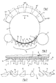
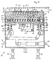
- the pre-carding zone is located between the Briseur 1 and the traveling lid 4, the carding zone extends over the area of the traveling lid, the post-carding zone is delimited by the traveling lid 4 and the doffer roller 3 and the sub-carding zone lies between the doffer roller 3 and the beater roller 1.
- the direction of rotation of the drum is marked with 8.
- the directions of rotation of the other elements are omitted for the sake of simplicity.
- FIG. 2 shows the stationary carding elements from FIG. 1 in a purely schematically stretched arrangement, that is to say arranged in a line next to one another.
- FIG. 1 a drum set 7 is also shown in detail on the drum 2, which is also shown in a stretched manner in FIG. 2.
- line 15 is at the same time the base line for the teeth described below of the sets described below.
- the set 9 has a so-called negative direction with respect to the direction of movement 8 of the drum set 7 with a relatively large angle ⁇ (see FIG. 3) while the last set 14 seen in the direction of movement 8 has a tooth directed in the opposite direction to that Set 9 and accordingly has a much smaller angle ⁇ .
- a negative set should not be understood to mean a set with a negative effect, but this designation is chosen only for the sake of simplicity in order to obtain a difference between the sets 9 to 11 and the sets 12 to 14.
- the angle ⁇ can be between 130 and 50 °.
- FIGS. 11 to 16 which have already been described in a CH application of the applicant with the number 04 103 / 88-3, which is why the description analogously essentially relates to the application of these elements in connection with the Invention is limited.
- rotatable carding elements 20 instead of the stationary carding elements 5, rotatable carding elements 20 (only one shown in FIG. 4) can be provided.
- carding elements 20 have a polygonal cross section and are around a shaft 21 in the direction of rotation 26 rotatable, wherein they can be fixed in positions in which the sets 22 to 25 of a set 18 of the drum 17 are opposite.
- positions can each be changed somewhat in that the distance A and B can be adapted to the requirement; this means that, for example, the distance A is chosen to be greater than the distance B in order to reinforce the carding effect within a position.
- the sets are different according to the needs. However, they can, for example, be chosen such that the clothing 23 corresponds to the clothing 9 of the stationary carding element 5, while the clothing 24 can correspond to the clothing 11, the clothing 25 to the clothing 13 or 12 and the clothing 22 to the clothing 14 of the carding element 5.
- a clothing combination can be selected which essentially corresponds to the clothing combination of FIGS. 1 to 3, with the advantage that the clothing combination can also be changed by rotating the carding elements 20 .
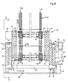
- FIG. 5 shows the elements of FIG. 4 seen from the direction of arrow II (FIG. 4) and has further details in order to illustrate the manner in which the carding element 20 can be provided in a rotatable manner.
- the drum 17 rotates by means of the shaft 16 and an actuator 33 rotates, by means of a shaft 34, the eccentric shaft 29, on which 2 eccentrics 30 are provided, which in turn accommodate an eccentric bearing body 31.
- This eccentric bearing body 31 also serves to rotatably receive the shaft 21, which is guided in a bearing support 32 within guide slots 37 (FIG. 6) such that the movements 27 and 28 indicated by arrows (see also FIGS. 4 and 7) can be carried out . These latter movements are performed by the eccentric 30.
- a servomotor 35 is provided, which is guided between guide surfaces 39 for movement in the directions 27 and 28, and which is connected via the shaft 36 to the shaft 21 of the rotatable carding element 20.
- the two servomotors 33 and 35 can be controlled via a controller (not shown) in order to select a desired combination of the sets, as is shown, for example, in FIG.
- a controller not shown
- the polygonal cross section has six clothing surfaces, so that more variations of clothing are possible than shown with FIG. 4.
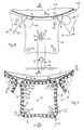
- FIGS. 8, 9 and 10 show a further variant of a carding element 40, in which the sets are not part of a firmly mounted set plate, but part of a chain link 41 (FIG. 9). However, since the sets can be the same as those shown in FIGS. 4 and 5, the sets are identified by the same reference numerals.
- the chain links 41 form the chain 42 with the aid of chain link rods 43 which are continuous in the axial direction of the carding element 40.
- tubular spacers 56 (FIG. 8) are provided, which are likewise mounted on the rods 43.
- spacers 56 are received in grooves 44 by sprockets 45, as is the case with a bicycle chain.
- the chain wheels 45 are provided on a continuous shaft 46, each at a mutual, predetermined distance (not marked), whereby the sum of all chains 42 forms the actual carding element 40.
- a continuous shaft 46 each at a mutual, predetermined distance (not marked)
- only two such shafts 46 can also be provided, as a result of which only two different sets can be provided.
- the shafts 46 are at their two ends in a bearing plate 47, respectively. 48 rotatably mounted, one of the shafts being connected to a servomotor 49.
- This servomotor is shown purely schematically in FIGS. 8 and 10. The rotation of the three other shafts, which are not driven separately by a servomotor, takes place by means of the chains 42.
- each groove 51 is endlessly shaped in such a way that the chain 42 forms the curvature with the radius R (FIG. 9) which is shown schematically by dash-dotted lines.
- This curvature as shown in Figure 9, for the sets 22, 23, 24 and. 25 kept the same.
- This curvature with the radius R corresponds to one of the axis of rotation (not shown) of the roller 2; 17 concentric curvature, provided the distance between the set 7; 18 of the roller 2; 17 and the one in action located set of the carding element 70 is the same over the entire length of the circumferential length of the set.
- guides 57 can be provided for each chain section (only shown for one in FIG. 9) which carries a different set, which supports the bars 43 in absorbing the pressure caused by the radial forces.
- FIGS. 9 and 10 show that more than one carding element 40 can be provided.
- a nonwoven guide element 52 is provided before and after a carding element 40 or between two carding elements 40.
- the element 52 ensures that the on the set 7; 18 of the roller 2; 17 lying fleece not by the centrifugal force, which with rotating roller 2; 18 acts on this fleece, is flung away between two carding elements 40, but is fed to the next carding element 40.
- each carding element 40 in the directions of movement 27 and 28 and in the direction of rotation.
- the bearing plate 47 has an axis 53 and the bearing plate 48 has a shaft 54. Both, that is, axis 53 and shaft 54, are coaxial with the axis of rotation 56 of the end shields 47, respectively. 48 fixed.
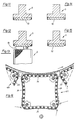
- FIGS. 11, 12, 13, 14 and 15 each show a stationary carding element 5, element 5 of FIG. 11 having a clothing 13 already shown, while FIGS. 12, 13, 14 and 15 show variations of clothing in comparison,
- FIGS. 12 and 13 are a corded surface 61 (also called a creased surface)
- FIG. 14 is a grooved set 60
- FIG. 15 is a shaft set 62.
- the various types of clothing are used based on empirical tests.
- FIG. 17 shows, with a carding element 89, a further variant of a carding element according to the invention, with a movable needle set 90.
- Each needle of this set 90 has a needle foot 91, which on the one hand has a linear up and down movement 92 and 93, with a view, by means mentioned below seen on Figure 17, and on the other hand can perform a back and forth movement 94 and 95, also seen with reference to Figure 12.
- the needle tips of the clothing 90 protrude at a predetermined distance M from an upper housing wall 96 of a housing 97 which extends across the width of the card and is rod-shaped when viewed from the outside.
- an angle of attack ⁇ which is formed by the needle wall 90.1 (not shown) and the surface 96.1 of the housing wall 96, is automatically changed with a change in the distance M at an angle of inclination ⁇ which is smaller or greater than 90 °.
- the angle of inclination ⁇ is formed by a line of symmetry S of the needle 90 which intersects the pivot axis Q of the needle foot 91 and an imaginary plane E which includes the pivot axes Q.
- the needle foot 91 has a spherical shape and, when using flat needles punched out of a metal plate, has a tapered needle shape and a disk-like shape.
- the needle foot is embedded in longitudinal grooves, seen in the longitudinal direction of a carding element, which have the supplementary form to the needle foot and are part of a base plate 99 (not shown).
- the longitudinal direction of a carding element runs in a direction perpendicular to the surface of the sheet provided with FIG. 17. That is, the base plate 99 (not shown) has as many grooves arranged side by side and in parallel as there are needle feet in the transverse direction to the base plate.
- the needle feet are covered with a rubber mat 100, in which the needles are effectively inserted, and a rigid plate 101.
- the plate 101 can be, for example, a metal or rigid plastic plate, in any case this plate 101 requires openings 102 in which the individual needles of the needle set 90 can move freely in order to be able to assume the various positions. It is not necessary to have an opening in the rubber mat 100 corresponding to the opening 102, since the rubber mat is so soft that the material adapts to the movements of the needles without having any significant or disruptive changes.
- the base plate 99, the rubber mat 100 and the cover plate 101 together form a coherent unit with a predetermined thickness, which is guided between two guide surfaces 103 and 104 in the displacement directions 94 and 95.
- the guide surfaces 103 and 104 are parts of a displacement element 105, which for vertical displacement in the displacement directions 92 and 93 are provided with plungers 106 distributed over the length of the displacement element 105, on each of which a plunger plate 107 is fixedly arranged at its free end.
- a guide plate 108 is provided as part of the housing 97 for guiding the plungers 106.
- the base plate 99 For the movement of the base plate 99 (not shown) in the directions of movement 94 and 95, the base plate 99 has a rack 109 at each of its two longitudinal ends, which is firmly connected to the base plate 99.
- gear wheel 110 In engagement with these racks is a gear wheel 110, which is connected to a shaft 111 in a rotationally fixed manner.
- the shaft 111 is also rotatably supported in supports (not shown) which are part of the displacement element 105.
- the distance (not shown) between the two racks is such that the displacement torque of each gearwheel acts as far as possible in the end region, seen in the longitudinal direction of the base plate, that is to say in the direction perpendicular to FIG. 13.
- the housing 97 can either be stationary on one as with the carriers 115, shown with dashed lines immovable machine part 116 may be provided or be provided with the servomotors 82 in an analogous manner as shown in FIG. 12 of the aforementioned CH patent application, so that the distances A.2 and B.2 can be variably adjusted, as described for FIG. 12 of the application CH 2312/89 were.
- FIG. 5 of application No. 3452/89 shows a carding plate
- FIG. 7 of the same application shows an overall arrangement which comprises this carding plate.
- the carding plate (also called comb segment) of application CH 3452/89 can also be provided with such a clothing or with clothing elements such that the intensity of the fiber processing increases in the direction of rotation of the drum.
- the reasons for the tangle of the fibers in the area of the carding plate according to CH 3452/89 or in the pre-carding zone of a card are not those for the tangle of the fibers in the sub-carding zone.
- There is a confusion in the fine cleaning or in the pre-carding zone because "shortly before" (viewed in the direction of rotation of the drum) new material has been fed to the drum or the drum. In the sub-carding zone, however, the confusion does not come about because of the supply of new material, but because of a work intervention by one element of the machine, namely the customer.
- the change in intensity is preferably brought about by changing the working angle of the clothing; that is, where the clothing is provided with needles or saw teeth ("tips"), by changing the angle between the longitudinal direction of the tip and a predetermined arbitrary reference (for example a tangential plane or a radial plane).
- This angle preferably changes within a predetermined circumferential range in such a way that the “tip” at the beginning of the range (viewed in the direction of rotation of the drum) extends in the direction of rotation of the drum and arises at the end of the range against this direction of rotation.
Landscapes
- Engineering & Computer Science (AREA)
- Textile Engineering (AREA)
- Preliminary Treatment Of Fibers (AREA)
Claims (21)
- Procédé pour nettoyer ou carder des fibres textiles entre un tambour rotatif de nettoyage ou de cardage (8) et des éléments (9, 10, 11, 12, 13, 14) entourant ce tambour (8), qui possèdent des types de garniture,
caractérisé par le fait que
lesdits types de garniture des éléments entourants (9, 10, 11, 12, 13, 14) sont prévus d'une manière différente, l'un par rapport à l'autre, dans le sens de mouvement du tambour rotatif (8), de telle sorte que, dans une zone circonférentielle prédéterminée du tambour (8), l'effet d'ouvraison (effet de nettoyage respectivement de cardage) est différent. - Procédé selon revendication 1,
caractérisé par le fait que
l'effet d'ouvraison augmente. - Procédé selon revendication 2,
caractérisé par le fait que
l'effet d'ouvraison est effectué par des pointes et le changement de l'effet d'ouvraison est causé par un changement de l'angle de travail des pointes. - Procédé selon revendication 3,
caractérisé par le fait que
l'angle de travail est changé depuis le début de ladite zone circonférentielle jusqu'a la fin de cette zone (vu dans le sens de rotation du tambour), depuis une valeur négative jusqu'a une valeur positive. - Procédé selon revendication 1,
caractérisé par le fait que
l'effet d'ouvraison augmente et diminue d'une manière alternante. - Procédé selon revendication 5,
caractérisé par le fait que
l'effet d'ouvraison augmente et diminue plus d'une fois, en forme d'ondes, d'une manière alternante. - Procédé selon revendication 6,
caractérisé par le fait que,
lors du changement en forme d'ondes, l'effet d'ouvraison augmente de telle manière que la hauteur moyenne d'onde augmente. - Procédé selon l'une des revendications précédentes,
caractérisé par le fait que
ladite zone circonférentielle se trouve dans la zone de cardage inférieure (5) d'une carde. - Procédé selon l'une des revendications 1 à 7,
caractérisé par le fait que
ladite zone circonférentielle se trouve dans la zone de cardage préliminaire (2) d'une carde. - Procédé selon l'une des revendications 1 à 7,
caractérisé par le fait que
ladite zone circonférentielle se trouve dans la zone de cardage principale respectivement postérieure d'une carde. - Procédé selon l'une des revendications 1 à 7,
caractérisé par le fait que
ladite zone se trouve dans une machine de nettoyage fin. - Dispositif de cardage ou de nettoyage avec un tambour rotatif de cardage ou de nettoyage (8), et avec des éléments (9, 10, 11, 12, 13, 14), prévus avec des garnitures, entourant ce tambour (8),
caractérisé par le fait que
le type de garniture d'éléments voisins (9, 10, 11, 12, 13, 14) est différent. - Dispositif selon revendication 12,
caractérisé par le fait que
le type de garniture est différent d'une telle manière que, dans le sens de mouvement du tambour (8), celui-ci est différemment agressif. - Dispositif selon revendication 13,
caractérisé par le fait que
le type de garniture augmente en agressivité. - Dispositif selon revendication 14,
caractérisé par le fait que
le type de garniture possède une agressivité en forme d'ondes, c'est-à-dire qui augmente et diminue. - Dispositif selon revendication 12,
caractérisé par le fait que
les éléments (9, 10, 11, 12, 13, 14) sont stationnaires. - Dispositif selon revendication 12,
caractérisé par le fait que
les éléments (9, 10, 11, 12, 13, 14) sont mobiles. - Dispositif selon revendication 17,
caractérise par le fait que
les éléments (9, 10, 11, 12, 13, 14) sont rotatifs de telle manière que, par la rotation de ceux-ci, un type de garniture différent est disponible pour le traitement de fibres. - Dispositif selon revendication 17,
caractérisé par le fait que
les éléments sont des chapeaux dits balladeurs (40). - Procédé selon revendication 19,
caractérisé par le fait que
des chapeaux balladeurs voisins (40) possèdent des garnitures différentes. - Dispositif selon revendication 16,
caractérisé par le fait que
les éléments (9, 10, 11, 12, 13, 14) sont prévus dans la zone de cardage inférieure d'une carde.
Applications Claiming Priority (2)
| Application Number | Priority Date | Filing Date | Title |
|---|---|---|---|
| CH434889 | 1989-12-04 | ||
| CH4348/89 | 1989-12-04 |
Publications (2)
| Publication Number | Publication Date |
|---|---|
| EP0431379A1 EP0431379A1 (fr) | 1991-06-12 |
| EP0431379B1 true EP0431379B1 (fr) | 1994-05-04 |
Family
ID=4274424
Family Applications (1)
| Application Number | Title | Priority Date | Filing Date |
|---|---|---|---|
| EP90122024A Revoked EP0431379B1 (fr) | 1989-12-04 | 1990-11-17 | Procédé et appareil pour le nettoyage ou cardage des fibres textiles |
Country Status (4)
| Country | Link |
|---|---|
| US (1) | US5142741A (fr) |
| EP (1) | EP0431379B1 (fr) |
| JP (1) | JPH03180515A (fr) |
| DE (1) | DE59005618D1 (fr) |
Families Citing this family (13)
| Publication number | Priority date | Publication date | Assignee | Title |
|---|---|---|---|---|
| FR2677378A1 (fr) * | 1991-06-07 | 1992-12-11 | Schlumberger Cie N | Carde dite "laine". |
| FR2705366B1 (fr) * | 1993-05-19 | 1995-06-30 | Schlumberger Cie N | Dispositif de réglage de la distance entre les cylindres travailleurs et le grand tambour et/ou entre le peigneur et le grand tambour sur une carde. |
| JP2717630B2 (ja) * | 1994-05-06 | 1998-02-18 | 日東紡績株式会社 | 梳綿機 |
| GB9512830D0 (en) * | 1995-06-23 | 1995-08-23 | Crosrol Ltd | Fibre opener device |
| US5672213A (en) * | 1995-08-18 | 1997-09-30 | Alcon Laboratories, Inc. | Liquid enzyme compositions containing aromatic acid derivatives |
| DE59804953D1 (de) | 1997-02-24 | 2002-09-05 | Rieter Ag Maschf | Hochleistungskarde |
| DE59806797D1 (de) * | 1997-09-12 | 2003-02-06 | Rieter Ag Maschf | Kardendeckel |
| DE10042205B4 (de) * | 2000-08-28 | 2004-10-21 | Hollingsworth Gmbh | Vorrichtung wie Karde oder Krempel für die Faserverarbeitung |
| DE102005012251B4 (de) * | 2005-03-15 | 2019-05-09 | Trützschler GmbH & Co Kommanditgesellschaft | Vorrichtung an einer Karde zur Verarbeitung von Textilfasern, z. B. Baumwolle, Chemiefasern u. dgl. mit einer Trommel |
| CN104278365B (zh) * | 2014-09-09 | 2018-11-06 | 盐城金大纺织机械制造有限公司 | 梳棉机双区辊筒式分梳盖板 |
| CH710221A1 (de) * | 2014-10-09 | 2016-04-15 | Graf + Cie Ag | Garnitur für die Bearbeitung von textilen Fasern |
| CH711166A1 (de) * | 2015-06-05 | 2016-12-15 | Graf + Cie Ag | Ganzstahlgarnitur. |
| CN113832576B (zh) * | 2021-09-15 | 2022-08-23 | 徐州市全鑫毛制品有限公司 | 一种绒毛制品生产用杂质处理装置 |
Family Cites Families (24)
| Publication number | Priority date | Publication date | Assignee | Title |
|---|---|---|---|---|
| GB190015155A (en) * | 1900-08-25 | 1901-06-22 | William Hall Cook | Improvements in the Construction of Filleting for Carding Engines more particularly that used for the Flats used on Revolving Flat Cards. |
| GB190906425A (en) * | 1909-03-17 | 1910-03-17 | Ralph Illingworth | Improvements in and in the Manufacture of Toothed Feed-rollers, Workers, Swifts and the like for Machines for Preparing or Treating Rags, Waste, Wool, and other Fibrous Materials. |
| US2703439A (en) * | 1953-11-30 | 1955-03-08 | Firth Carpet Company Inc | Means for producing irregular yarns |
| DE1106653B (de) * | 1957-11-11 | 1961-05-10 | Herbert Hausmann | Kratzenbeschlag fuer die Deckel von Karden |
| FR1493015A (fr) * | 1966-07-11 | 1967-08-25 | Garniture rigide à dents, double cardante, pour le cardage des fibres textiles | |
| JPS5111211B1 (fr) * | 1968-04-19 | 1976-04-09 | ||
| US3824650A (en) * | 1968-04-19 | 1974-07-23 | Nagoya Metallic Card Co Ltd | Apparatus and process for transferring a fiber web |
| CH467349A (de) * | 1968-06-11 | 1969-01-15 | Graf & Co Ag | Kardengarnitur |
| CH521454A (de) * | 1970-06-03 | 1972-04-15 | Graf & Co Ag | Kardengarnitur |
| US4090276A (en) * | 1971-12-28 | 1978-05-23 | Glen Walton Company Limited | Textile carding |
| DE2825506A1 (de) * | 1978-06-10 | 1979-12-20 | Truetzschler & Co | Kardiergarnitur |
| US4291438A (en) * | 1979-02-17 | 1981-09-29 | Kabushiki Kaisha Toyoda Jidoshokki Seisakusho | Fiber feeding roller of open-end spinning apparatus |
| US4398318A (en) * | 1981-04-30 | 1983-08-16 | Ashworth Bros., Inc. | Card clothing for carding machine elements |
| DE3265065D1 (en) * | 1982-05-29 | 1985-09-05 | Wolters Peter Fa | Carding bar |
| DD225599A3 (de) * | 1982-12-30 | 1985-07-31 | Textima Veb K | Garnitur fuer kardiersegmente an karden |
| DE3333618A1 (de) * | 1983-09-17 | 1985-04-18 | Trützschler GmbH & Co KG, 4050 Mönchengladbach | Abdeckung fuer die walze einer spinnereivorbereitungsmaschine |
| EP0138778B1 (fr) * | 1983-10-05 | 1991-09-11 | Marcello Giuliani | Carde à chapeaux pourvue d'éléments auto-nettoyants en forme de lame ou de peigne |
| ES288973Y (es) * | 1984-10-11 | 1987-02-01 | Sole Leris Roger | Guarnicion rigida para chapones para cardas perfeccionada. |
| DE8430562U1 (de) * | 1984-10-18 | 1985-02-21 | Staedtler & Uhl, 8540 Schwabach | Saegezahn-stanzteil als garnitur fuer ein kaemmsegment einer kammwalze fuer textilmaschinen |
| CH664165A5 (de) * | 1984-11-09 | 1988-02-15 | Neidhart & Co Ag | Verfahren zum kardieren sowie eine vorrichtung zur durchfuehrung des verfahrens auf einer krempel. |
| IT1201259B (it) * | 1985-03-21 | 1989-01-27 | Marcello Giuliani | Carda a capelli fissi con cedimento elastico e registrazione di inclinazione |
| DE3618801A1 (de) * | 1986-06-04 | 1987-12-10 | Wolters Peter | Kardierstab |
| CN1022337C (zh) * | 1989-03-23 | 1993-10-06 | 里特机械公司 | 纤维网除尘器 |
| EP0403989B1 (fr) * | 1989-06-21 | 1993-11-24 | Maschinenfabrik Rieter Ag | Garniture de carde |
-
1990
- 1990-11-17 EP EP90122024A patent/EP0431379B1/fr not_active Revoked
- 1990-11-17 DE DE59005618T patent/DE59005618D1/de not_active Revoked
- 1990-11-28 JP JP2323406A patent/JPH03180515A/ja active Pending
- 1990-12-04 US US07/621,979 patent/US5142741A/en not_active Expired - Fee Related
Also Published As
| Publication number | Publication date |
|---|---|
| JPH03180515A (ja) | 1991-08-06 |
| DE59005618D1 (de) | 1994-06-09 |
| EP0431379A1 (fr) | 1991-06-12 |
| US5142741A (en) | 1992-09-01 |
Similar Documents
| Publication | Publication Date | Title |
|---|---|---|
| EP0431379B1 (fr) | Procédé et appareil pour le nettoyage ou cardage des fibres textiles | |
| DE69321232T2 (de) | Vorrichtung zum Rauhen von Geweben oder Gestricken mit Spannungsteuerung | |
| DE602808C (de) | Nadelwalzenpaar zum Aufloesen von Fasergut | |
| CH626660A5 (fr) | ||
| DE2343064A1 (de) | Vorrichtung zur herstellung von faservliesen aus textilen faserstoffen u. dgl | |
| EP0403989B1 (fr) | Garniture de carde | |
| EP3162927B1 (fr) | Cardeuse à chapeaux tournants | |
| DE10140864A1 (de) | Vorrichtung zum Vernadeln eines förderbaren Faservlieses | |
| DE2819292B2 (de) | Vorrichtung zum Öffnen von Faserballen | |
| CH675886A5 (fr) | ||
| DE3786267T2 (de) | Verfahren und Vorrichtung zur kontinuierlichen Aufbereitung von Pflanzenstengeln. | |
| DE102005001241A1 (de) | Abzugswalzen einer Kämmmaschine | |
| DE1510252A1 (de) | Verfahren und Vorrichtung zum parallelen Ausrichten von Textilfasern | |
| CH695615A5 (de) | Vorrichtung an einer Karde für Textilfasern, z.B. Baumwolle oder Chemiefasern. | |
| EP0365856B1 (fr) | Dispositif de courroie transversal à la sortie d'une machine de cardage | |
| DE3334912C1 (de) | Karde oder Krempel zum wahlweisen Herstellen von laengsorientierten Vliesen oder Wirrvliesen | |
| DE1510218A1 (de) | Vorrichtung zum kontinuierlichen Entwirren und Strecken von Fasern | |
| DE2624367C2 (de) | Verfahren zum Ausscheiden von Verunreinigung aus einem Faserbelag und Reinigungsvorrichtung zur Ausfürhrung dieses Verfahrens | |
| EP1917387A1 (fr) | Cable a dents de scie | |
| DE1410604A1 (de) | Krempelmaschine | |
| EP1277859B1 (fr) | Dispositif pour défibrer une mèche pour un métier à filer à bout libre | |
| DE4110297A1 (de) | Vorrichtung zum reinigen und oeffnen von in flockenform befindlichem fasergut, z. b. baumwolle, synthetischem fasergut u. dgl. | |
| DE4321351C1 (de) | Fasertransport- und Kämmeinrichtung | |
| EP1697569B1 (fr) | Surface d'appui et element d'appui | |
| WO2007048262A2 (fr) | Cylindre d'ouverture et puits de remplissage pour machine a carder |
Legal Events
| Date | Code | Title | Description |
|---|---|---|---|
| PUAI | Public reference made under article 153(3) epc to a published international application that has entered the european phase |
Free format text: ORIGINAL CODE: 0009012 |
|
| 17P | Request for examination filed |
Effective date: 19910412 |
|
| AK | Designated contracting states |
Kind code of ref document: A1 Designated state(s): CH DE ES FR GB IT LI |
|
| 17Q | First examination report despatched |
Effective date: 19931014 |
|
| GRAA | (expected) grant |
Free format text: ORIGINAL CODE: 0009210 |
|
| AK | Designated contracting states |
Kind code of ref document: B1 Designated state(s): CH DE ES FR GB IT LI |
|
| PG25 | Lapsed in a contracting state [announced via postgrant information from national office to epo] |
Ref country code: FR Effective date: 19940504 |
|
| REF | Corresponds to: |
Ref document number: 59005618 Country of ref document: DE Date of ref document: 19940609 |
|
| ITF | It: translation for a ep patent filed | ||
| PG25 | Lapsed in a contracting state [announced via postgrant information from national office to epo] |
Ref country code: ES Free format text: LAPSE BECAUSE OF FAILURE TO SUBMIT A TRANSLATION OF THE DESCRIPTION OR TO PAY THE FEE WITHIN THE PRESCRIBED TIME-LIMIT Effective date: 19940805 |
|
| GBT | Gb: translation of ep patent filed (gb section 77(6)(a)/1977) |
Effective date: 19940712 |
|
| EN | Fr: translation not filed | ||
| PLBI | Opposition filed |
Free format text: ORIGINAL CODE: 0009260 |
|
| 26 | Opposition filed |
Opponent name: TRUETZSCHLER GMBH & CO. KG Effective date: 19950103 |
|
| PGFP | Annual fee paid to national office [announced via postgrant information from national office to epo] |
Ref country code: GB Payment date: 19951016 Year of fee payment: 6 |
|
| PGFP | Annual fee paid to national office [announced via postgrant information from national office to epo] |
Ref country code: DE Payment date: 19951020 Year of fee payment: 6 |
|
| PGFP | Annual fee paid to national office [announced via postgrant information from national office to epo] |
Ref country code: CH Payment date: 19951103 Year of fee payment: 6 |
|
| PLBF | Reply of patent proprietor to notice(s) of opposition |
Free format text: ORIGINAL CODE: EPIDOS OBSO |
|
| RDAG | Patent revoked |
Free format text: ORIGINAL CODE: 0009271 |
|
| STAA | Information on the status of an ep patent application or granted ep patent |
Free format text: STATUS: PATENT REVOKED |
|
| 27W | Patent revoked |
Effective date: 19951202 |
|
| GBPR | Gb: patent revoked under art. 102 of the ep convention designating the uk as contracting state |
Free format text: 951202 |
|
| REG | Reference to a national code |
Ref country code: CH Ref legal event code: PL |
|
| K1C1 | Correction of patent application (title page) published |
Effective date: 19910612 |