EP0427202A2 - Farbstrahlaufzeichnungsvorrichtung - Google Patents
Farbstrahlaufzeichnungsvorrichtung Download PDFInfo
- Publication number
- EP0427202A2 EP0427202A2 EP90121220A EP90121220A EP0427202A2 EP 0427202 A2 EP0427202 A2 EP 0427202A2 EP 90121220 A EP90121220 A EP 90121220A EP 90121220 A EP90121220 A EP 90121220A EP 0427202 A2 EP0427202 A2 EP 0427202A2
- Authority
- EP
- European Patent Office
- Prior art keywords
- time
- cap member
- ink
- suction
- Prior art date
- Legal status (The legal status is an assumption and is not a legal conclusion. Google has not performed a legal analysis and makes no representation as to the accuracy of the status listed.)
- Granted
Links
Images


Classifications
-
- B—PERFORMING OPERATIONS; TRANSPORTING
- B41—PRINTING; LINING MACHINES; TYPEWRITERS; STAMPS
- B41J—TYPEWRITERS; SELECTIVE PRINTING MECHANISMS, i.e. MECHANISMS PRINTING OTHERWISE THAN FROM A FORME; CORRECTION OF TYPOGRAPHICAL ERRORS
- B41J2/00—Typewriters or selective printing mechanisms characterised by the printing or marking process for which they are designed
- B41J2/005—Typewriters or selective printing mechanisms characterised by the printing or marking process for which they are designed characterised by bringing liquid or particles selectively into contact with a printing material
- B41J2/01—Ink jet
- B41J2/135—Nozzles
- B41J2/165—Preventing or detecting of nozzle clogging, e.g. cleaning, capping or moistening for nozzles
- B41J2/16517—Cleaning of print head nozzles
- B41J2/1652—Cleaning of print head nozzles by driving a fluid through the nozzles to the outside thereof, e.g. by applying pressure to the inside or vacuum at the outside of the print head
- B41J2/16523—Waste ink collection from caps or spittoons, e.g. by suction
Definitions
- the present invention relates to an ink jet recording apparatus in which a linear array of small nozzles and pressure generators communicating with respective ones of those nozzles are provided, and dots are formed on a recording sheet in such a manner that the pressure generators pressure feed ink to the nozzles, and in turn the nozzles shoot ink jets onto the recording sheet.
- a linear array of small nozzles is formed on the top of the print head.
- the print head is moved over the surface of a recording sheet by a carriage.
- paper particles from the recording sheet and dust stuck to the same tend to adhere to the nozzle openings.
- the nozzles thus tend to get clogged with the paper particles and dust. This leads to printing defects.
- air bubbles sometimes enter into a connecting portion between the ink tank and the nozzles. In an extreme case, the supply of ink to the nozzles is halted, resulting in no print.
- an ink sucking device in which a negative pressure generating unit, which applies a negative pressure to a cap member for hermetically sealing the nozzle openings of the print head, is installed in the printer.
- a negative pressure generating unit which applies a negative pressure to a cap member for hermetically sealing the nozzle openings of the print head.
- the user pushes a print recovery button on a control panel.
- the negative pressure generating unit is driven to produce a negative pressure within the space of the cap member, and hence to forcibly expel a larger amount of ink from the nozzles than in normal printing.
- the sucking of the ink paper particles and dust adhering to the nozzle openings are washed away with the ink jets. In this way, the printer is recovered from the clogging of the nozzles.
- Air bubbles are normally present outside from the nozzle openings.
- the ink thus must be sucked up in such an amount as to extract the air bubble from the nozzle openings. According technically, to eliminate air bubbles, the amount of the sucked ink is much larger than that for removing paper particles and dust.
- the forcible discharge of the ink consumes a great amount of ink, which is much larger than that in normal printing.
- the usual practice is to limit the amount of ink discharged for each operation of the recovery switch to a preset value.
- the amount of ink discharged during one suction operation is set at such an amount as to remove the clogging of the nozzles that frequently occurs due to accumula tion of paper particles and dust thereon. This amount is 0.5 cc, for example. Therefore, if a user mistakenly pushes the recovery button, the amount of ink consumed is about 0.55 cc at most.
- the recovery button In case where about 2 cc of ink must be discharged, for example, to remove air bubble is removed, the recovery button must be pushed many times. This work is cumbersome for the user. The number of button pushings can be reduced by increasing the amount of ink discharged by one suction operation to such an extent as to remove the bubbles. Where the technique is employed, the ink is excessively discharged or sucked for curing light printing defects caused by paper particles and dust stuck to the nozzles, which frequently occurs.
- an object of the present invention is to provide an ink jet recording apparatus with a printing defect recovery function which limits the amount of ink required for curing light printing defects, and to reduce the number of ink sucking operations for removing air bubbles.
- the present invention relates to a technique for removing light printing defects due to paper particles, dust, and like, and heavy printing defects due to mixing of air bubbles into the ink jets.
- the present invention also provides an ink jet recording apparatus with a printing defect recovery function which reduces the amount of time a brush is operated for removing the paper particles and dust.
- a microcomputer determines whether a printing defect is a light printing defect, that is, a defect caused by paper particles and dust stuck to the nozzles, or a heavy printing defect, that which, is a defect caused by air bubbles entering the ink flow paths. The determination is made on the basis of intervals of operating a print recovery button mounted on a chassis of the recording apparatus.
- the computer instructs the placement of a cap member on the front face of the nozzles of the print head and the application of a negative pressure to the nozzles, thereby to reduce the amount of ink emitted from the nozzles.
- the computer increases the amount of ink jetted.
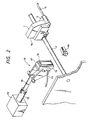
- Fig. 1 is a perspective view showing the construction of an ink jet printer according to the present invention.
- reference numeral 1 designates an ink jet print head having an array of nozzles.
- the print head is disposed with the openings of the nozzles facing a print surface.
- the print head is mounted on a carriage 4 which reciprocatively moves in the direction of width of a recording sheet 3 along a pair of guide rails 2 and 2′.
- An ink tank (not shown) supplies ink through a tube 5 to the print head 1.
- Reference numeral 6 designates a platen to support the recording sheet 3.
- the platen 6 is rotatably supported at both ends by a pair of base plates 7 and 9.
- a cap member 10, which is to be in contact with the front face of the print head 1, is disposed on the left side of the base plate 8 and out of a print region.
- the cap member 10 communicates with a suction pump by means of a tube 11.
- Fig. 2 is a perspective view showing the details of the cap member 10.
- the cap member 10 is retractably coupled with a solenoid 12 by means of a rod 13 and an arm 14.
- a resilient member 16 which is provided on a base member 15, is shaped so as to enclose the front end containing a nozzle face 1a of the print head 1, and defines a nozzle receiving chamber 17.
- a negative pressure as transferred from a pump 20 enters the nozzle receiving chamber 17.
- the detector produces a signal and sends it to a control circuit 26 to be given later.
- the solenoid 12 is driven to move the base member 15 of the cap member toward the nozzle face 1a.
- the cap member 10 hermetically seals the nozzle face 1a of the print head 1.
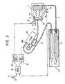
- Fig. 3 is a block and schematic diagram, showing an arrangement of the printer containing an ink supply flow system, an ink suction flow system operating in a print recovery mode, and a control system for print recovery.
- a suction pump 20 is coupled at the suction port 20a with the nozzle receiving chamber 17 of the cap member 10 by way of the tube 11, and at the discharge port 20b with a used-ink tank 23 of an ink cartridge 22 by way of a tube 21.
- An ink tank 24 contained in the cartridge 22 is connected to the print head 10 by way of a tube 5.
- the control circuit 26 which executes sequences of print recovery process steps, is arranged as shown in Fig. 4.
- the control circuit 26 is composed of a microcomputer 33 including a CPU 30, a ROM 31 and a RAM 32, a clock circuit 34, and a memory 35 for storing time data representative of time of pushing of the recovery button 27.
- the circuit 26 is programmed so as to execute a sequence of operations as given below.
- the recovery button 27 which is provided on an operating panel of the printer chassis, is pushed, the position detector 18 produces a signal.
- the control circuit sends a signal to the solenoid drive circuit 28 (Fig. 3).
- the drive circuit 28 drives the solenoid 12 to press the cap member 10 against the print head 1.
- the control circuit sends a signal to the pump drive circuit 29 to operate the suction pump 20 for a preset time.
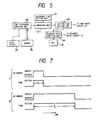
- Fig. 5 is a functional block diagram showing a model of the function to be realized by the microcomputer 33.
- the circuit is composed of time difference computing unit 40, reference time setting unit 41, comparing unit 42, suction time setting unit 43, and solenoid drive unit 44.
- the time difference computing unit 40 computes a time difference ⁇ T between time data of the previous pushing of the recovery button 27 as stored in the memory 35 and the time of the present pushing.
- the reference time setting unit 41 stores a reference time T0 to determine a type of printing defect.
- the comparing unit 42 compares the time difference ⁇ T derived from the time difference computing unit 40 with the reference time T0.
- the suction time setting unit 43 selects a suction time T S long enough to wash away paper particles and dust or a suction time T L long enough to remove air bubbles on the basis of the result of the comparison.
- the solenoid drive unit 44 energizes the solenoid 12 by a signal from the position detector 18, and de-energized the same when the suction is completed.
- a user pushes the recovery button 27, which is provided on the chassis of the printer (step 200). Then, the carriage 4 is moved toward the cap member 10 under control of a carriage control circuit (not shown). The carriage 4 faces the cap member 10. At this time, the position detector 18 produces a signal (step 201). In response to the signal, the microcomputer 33 stores time data t1 derived from the clock circuit 34, and then sends a signal to the solenoid drive circuit 28 to energize the solenoid 12. As a result, the cap member 10 hermetically closes the nozzle face 1a of the print head 1 (step 202).
- the present pushing of the button is the first pushing after power on.
- the CPU determines that the time difference ⁇ T is longer than the reference time T0 (step 204).
- the reference time T0 is the time that will elapse until the nozzles get clogged by foreign material, such as paper particles and dust, when the printer is operated in an ordinary printing mode, and is usually approximately five to ten hours. Printing defects due to foreign material adhering to the nozzle openings occur on the average of about five to ten hours after the printer is continuously operated, although the time depends on ambient conditions of the printer installed and the quality of paper. This fact was experimentally confirmed by the present inventors.
- the computer 33 issues a signal to the pump drive circuit 29, so that the suction pump 20 is operated to generate a negative pressure in the nozzle receiving chamber 17 of the cap member 10 (step 205).
- the negative pressure acts on the nozzle face 1a to extract ink through the nozzle openings. With the flow of the ink, paper particles and dust sticking to the nozzle openings are washed away.
- time T S that is, the time taken until the pump has sucked an amount of ink necessary for removing the foreign material, elapses, viz. the time necessary for sucking ink of approximately 0.5 cc (this ink amount is denoted as Q a ) elapses (Fig.
- the microcomputer 33 stops the operation of the pump 20, and at the same time de-energizes the solenoid 12 to separate the cap member 10 from the print head 1 (step 207). Under this condition, the print head 1 is operable in a print region and starts the printing operation again.
- a printing defect occurs again after a relatively short time of ten and several minutes to one hour from the previous pushing of the button 27.
- the user pushes the button 27 again (step 200).
- the carriage 4 is moved and reaches the position of the cap member 10, and the position detector 18 produces a signal (step 201).
- the microcomputer 33 stores time data 12 from the clock circuit 34 into the memory 35, and sends a signal to the solenoid drive circuit 28.
- the cap member 10 is pressed against the nozzle openings of the print head 1 (step 202).
- the microcomputer 33 computes a time difference between time t1 of the previous ink suction as stored in the memory 35, and time t2 of the present ink suction, viz.
- the computer When the nozzle face 1a of the print head 1 is hermetically closed by the cap member 10, the computer operates the pump 20 to apply a negative pressure to the nozzle receiving chamber 17 of the cap member 10 (step 208).
- the negative pressure acting on the nozzle face 1a ink is discharged from the ink flow path through the nozzle openings into the nozzle receiving chamber. Together with the discharged ink, the air bubbles are attracted toward the nozzle openings and discharged outside from the nozzles (Fig. 7, waveforms II).
- step 209 the microcomputer 33 stops the operation of the pump 20, and de-energizes the solenoid 12 to separate the cap member 10 from the nozzle openings. Under this condition, the carriage 4 is movable in the print region (step 207).
- the carriage 4 retracts to the position of the cap member 10 and the position detector 18 produces a signal.
- the microcomputer 33 stores the time data t3 as applied from the clock circuit 34 into the memory 35, and then sends a signal to the solenoid drive circuit 28.
- the solenoid 12 is energized to make the cap member 10 contact with the print head 1 (step 202).
- the type of printing defect is determined on the basis of the time interval between the pushings of the recovery button.
- the amount of ink to be sucked is set according to the result of this determination.
- a small amount of ink is sucked.
- a large amount of ink is sucked. Accordingly, the number of pushings of the recovery button as required for curing heavy printing defects is reduced, and hence the printer can be quickly recovered from its abnormal state.
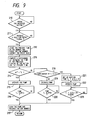
- Fig. 8 shows a second embodiment of the present invention in terms of the functions to be realized by the microcomputer 33 constituting the control circuit 26.
- the control circuit is composed of time difference computing unit 40, reference time setting unit 41, comparing unit 42, suction time setting unit 43, solenoid drive unit 44, and suction time prolong unit 48.
- the time difference computing unit 40 computes a time difference ⁇ T between time data as stored in the memory 35 and the times of pushing the recovery button.
- the reference time setting unit 41 stores a reference time T0 to determine the type of printing defect.
- the comparing unit 42 compares the time difference ⁇ T derived from the time difference computing unit 40 with the reference time T0.
- the suction time setting unit 43 selects a suction time T S long enough to wash away paper particles and dust or a suction time T L long enough to remove air bubbles on the basis of the result of the comparison.
- the solenoid drive unit 44 energizes the solenoid 12 with a signal from the position detector 18, and de-energizes the same when suction is completed.
- the suction time extending unit 48 increments the suction time by a fixed time ⁇ T a every N number of pushings of the recovery button.
- the user pushes the recovery button 27, which is provided on the chassis of the printer (step 210). Then, the carriage 4 is moved toward the cap member 10 under the control of a carriage control circuit (not shown). The carriage 4 faces the cap member 10. At this time, the position detector 18 produces a signal (step 211). In response to the signal, the microcomputer 33 stores time data t1 derived from the clock circuit 34, and then sends a signal to the solenoid drive circuit 28 to energize the solenoid 12. As a result, the cap member 10 hermetically closes the nozzle face 1a of the print head 1 (step 212).
- step 216 When time T S , which is the time taken until the pump has sucked an amount of ink necessary for removing the foreign material, elapses (step 216), the microcomputer 33 stops the operation of the pump 20, and at the same time de-energizes the solenoid 12 to separate the cap member 10 from the print head 1 (step 217; Fig. 10, waveforms I). Under this condition, the print head 1 is operable within the print region gnd starts the printing operation again.
- the printing defect occurs again after a relatively short time of ten and several minutes to one hour from the previous pushing of the button 27.
- the user pushes the button 27 again (step 210).
- the carriage 4 is moved and reaches the position of the cap member 10, and the position detector 18 produces a signal (step 211).
- the microcomputer 33 stores time data t2 from the clock circuit 34 into the memory 35, and sends a signal to the solenoid drive circuit 28.
- the cap member 10 is pressed against the nozzle openings of the print head 1 (step 212).
- the microcomputer 33 operates the pump 20 (step 219), and stops the same after the time T L taken for sucking the amount Q L of ink, which is necessary for removing the air bubbles (step 220), and separates the cap member 10 from the print head 1 (step 217; Fig. 10, waveforms II).
- the printing defect due to the air bubbles will occur again within a very short of time, e.g., ten and several minutes. If such printing defect occurs and the user pushes the recovery button 27 (step 210), the carriage 4 is moved to the position of the cap member and the position detector 18 produces an output signal (step 211). At this time, the microcomputer 33 sends a signal to the solenoid drive circuit 28. Then, the cap member 10 is pressed against the nozzle openings of the print head 1 (step 212).
- the suction time for the bubble removal is incremented by time ⁇ T x N every N number of pushings to be T L + ⁇ T x N (step 221).
- the printing defect found is a heavy printing defect requiring frequent pushings of the recovery button, it can be cured by incrementing the amount of the ink to be sucked, with the feature of incrementing the suction time for the bubble removal.
- the inventors conducted an experiment to cure a heavy printing defect due to air bubbles into the ink flow path.
- two printers were used; one a conventional printer in which the amount of ink to be sucked is fixed at 2 cc, and the other a printer according to the instant embodiment which increments the amount of the sucked ink every time the recovery button is pushed.
- the results of the experiment are shown in Table 2.
- TABLE 2 Number of recovery operations Conventional printer Present Invention 1st time 2 1 2nd time 2 2 3rd time 2 3 4th time 2 4 ⁇ Ready for print 5th time 2 ⁇ Ready for print Total ink consumption 10 10
- the printer of the invention can save the number of the pushings of the button by one time, and proportionally reduce the print rest time required for the ink suction operation.
- the interval between the operations of the recovery button is obtained from the time data of the clock circuit. If required, a timer unit operated in connection with the recovery button may be used for obtaining the button operation interval.
- the amount of sucked ink is determined on the basis of the time interval between button pushings.
- the ink suction time and the amount of sucked ink by the cap member can be determined on the basis of the quantities of print and paper feed.
- Fig. 11 shows a third embodiment of the present invention in the form of an arrangement of the control circuit 26.
- the control circuit 26 is composed of a microcomputer 54 including a CPU 51, a ROM 52 and a RAM 53, a counter 55 for counting a print quantity, such as the number of printed characters, the number of lines, and an amount of paper feed, and a memory 57 for storing data of the counted print quantity derived from the counter 55 when the recovery button 27 is pushed. It is programmed so as to execute a sequence of operations as given below.
- the recovery button 27 which is provided on an operating panel of the printer chassis, is pushed, the position detector 18 shown in Fig. 2 produces a signal.
- the control circuit sends a signal to the solenoid drive circuit 28.
- the drive circuit 28 drives the solenoid 12 to control circuit sends a signal to the pump drive circuit 29 to operate the suction pump 20 for a preset time.
- Fig. 12 is a functional block diagram showing a model of the function to be realized by the microcomputer 54.
- the circuit is composed of print quantity difference computing unit 58, reference print quantity setting unit 59, comparing unit 60, suction time setting unit 61, and solenoid drive directing unit 62.
- the print quantity difference computing unit 58 computes a print quantity difference AL between print quantity data stored in the memory 57 and data output from the counter 55 when the recovery button 27 is pushed.
- the reference print quantity setting unit 59 stores a reference print quantity L0 to determine the type of printing defect.
- the comparing unit compares the print quantity difference data from the print quantity difference computing unit 58 with the reference print quantity L0.
- the suction time setting unit 61 selects a suction time T S long enough to wash away paper particles and dust or a suction time T L long enough to remove air bubbles on the basis of the result of the comparison.
- the solenoid drive directing unit 62 energizes the solenoid 12 by a signal from the position detector 18, and de-energizes the same when the suction is completed.
- the microcomputer 54 Upon start of a printing operation, the microcomputer 54 causes the counter 55 to count the print quantity (step 230). During the printing operation, if a printing defect is found, the user pushes the recovery button 27, which is provided on the chassis of the printer (step 231). Then, the carriage 4 is moved toward the cap member 10 under control of a carriage control circuit (not shown). The carriage 4 faces the cap member 10. At this time, the position detector 18 produces a signal (step 232). In response to the signal, the microcomputer 54 fetches the print quantity l1 at the instant that the recovery button 27 produces a signal, and stores it in the memory 57. Further the microcomputer 54 sends a signal to the solenoid drive circuit 28 to energize the solenoid 12.
- the cap member 10 hermetically closes the nozzle face 1a of the print head 1 (step 233).
- the present pushing of the button is the first pushing after power on. Accordingly, the CPU determines that the print quantity difference ⁇ L is larger than the reference print quantity L0 (step 235).
- the computer 54 issues a signal to the pump drive circuit 29, so that the suction pump 20 is operated to generate a negative pressure in the nozzle receiving chamber 17 of the cap member 10 (step 236).
- the negative pressure acts on the nozzle face 1a to extract ink through the nozzle openings. With the flow of the ink, paper particles and dust stuck to the nozzle openings are washed away.
- time T S which is the time taken until the pump has sucked an amount of ink necessary for removing the foreign material, elapses (step 237)
- the micro computer 54 stops the operation of the pump 20, and at the same time de-energizes the solenoid 12 to separate the cap member 10 from the print head 1 (step 238). Under this condition, the print head 1 is operable in a print region and starts the sprinting operation again.
- a printing defect occurs again after a relatively short time of ten and several lines to several pages from the previous pushing of the button 27.
- the user pushes the button 27 again (step 231).
- the carriage 4 is moved and reaches the position of the cap member 10, and the position detector 18 produces a signal (step 232).
- the microcomputer 54 stores print quantity data l2 from the counter 55 in the memory 57, and sends a signal to the solenoid drive circuit 28.
- the cap member 10 is pressed against the nozzle openings of the print head 1 (step 233).
- the reference print quantity L0 is selected on the basis of this figure (250) of the number of lines until the recovery button is pushed again.
- the printing defect due to foreign material stuck to the nozzle openings when the printer is continuously operated, will happen between approximately 1,000 and 10,000 lines, although the numbers of lines in a given situation will of course depend on ambient conditions and the quality of paper used. This fact was experimentally confirmed by the inventors.
- the microcomputer 54 stops the operation of the pump 20, and de-energizes the solenoid 12 to separate the cap member 10 from the nozzle openings. Under this condition, the carriage 4 is movable in the print region (step 238).
- the carriage 4 retracts to the position of the cap member 10 and the position detector 18 produces a signal.
- the microcomputer 54 stores the time data 13, which comes from the clock circuit 34, in the memory 57, and, then sends a signal to the solenoid drive circuit 28. By this signal, the solenoid 12 is energized to make the cap member 10 contact with the print head 1 (step 233).
- the ink jet printer of the instant embodiment detects the amounts of paper particles and dust, which are proportional to the print quantity. Accordingly, the recovery of the printer from the printing defect is quickened.
- Fig. 14 shows a fourth embodiment of the present invention in terms of the function to be realized by the microcomputer 54.
- the circuit is composed of print quantity difference computing unit 65, reference print quantity setting unit 66, comparing unit 67, suction time setting unit 68, suction time prolong unit 69, and solenoid drive unit 70.
- the print quantity difference computing unit 65 computes a print quantity difference ⁇ L between print quantity data stored in the memory 57 and data output from the counter 55 when the recovery button 27 is pushed.
- the reference print quantity setting unit 66 stores a reference print quantity L0 to determine the type of printing defect.
- the comparing unit 67 compares the print quantity difference data from the print quantity difference computing unit 65 with the reference print quantity L0.
- the suction time setting unit 68 selects a suction time T S long enough to wash away paper particles and dust or a suction time T L long enough to remove air bubbles on the basis of the result of the comparison.
- the suction time extending unit 69 increments the suction time by fixed time T a every the N number of pushings of the recovery button.
- the solenoid drive unit 70 energizes the solenoid 12 by a signal from the position detector 18, and de-energizes the same when the suction is completed.
- the microcomputer 54 Upon start of a printing operation, the microcomputer 54 causes the counter 55 to count the print quantity (step 250). During the printing operation, if a printing defect is found, the user pushes the recovery button 27, which is provided on the chassis of the printer (step 251). Then, the carriage 4 is moved toward the cap member 10 under control of a carriage control circuit (not shown). The carriage 4 faces the cap member 10. At this time, the position detector 18 produces a signal (step 252). In response to the signal, the microcomputer 54 fetches the print quantity l1 at the instant that the recovery button 27 produces a signal, and stores it in the memory 57. Further, the microcomputer 54 sends a signal to the solenoid drive circuit 28 to energize the solenoid 12.
- the cap member 10 is pressed against the print head 1 (step 253).
- the computer 54 issues a signal to the pump drive circuit 29, so that the suction pump 20 is operated to generate a negative pressure in the nozzle receiving chamber 17 of the cap member 10 (step 256).
- the negative pressure acts on the nozzle face 1a to extract ink through the nozzle openings. With the flow of the ink, paper particles and dust stuck to the nozzle openings are washed away.
- step 257 When time T S , which is the time taken until the pump has sucked an amount of ink necessary for removing the foreign material, elapses (step 257), the microcomputer 54 stops the operation of the pump 20, and at the same time de-energizes the solenoid 12 to separate the cap member 10 from the print head 1 (step 258). Under this condition, the print head 1 is operable in a print region and starts the printing operation again.
- a printing defect occurs again after a relatively short time of several lines to several pages from the previous pushing of the button 27.
- the user pushes the button 27 again (step 251).
- the carriage 4 is moved and reaches the position of the cap member 10, and the position detector 18 produces a signal (step 252).
- the microcomputer 54 stores print quantity data l2 from the counter 55 in the memory 57, and sends a signal to the solenoid drive circuit 28.
- the cap member 10 is pressed against the nozzle openings of the print head 1 (step 253).
- the printing defect due to the air bubbles will occur again within a very short of time, e.g., ten and several minutes. If such printing defects occurs and a user pushes the recovery button 27 (step 251), the carriage 4 is moved to the position of the cap member 10 and the position detector 18 produces an output signal (step 252). At this time, the microcomputer 33 stores the print quantity l3 of the counter 55 into the memory 57, and sends a signal to the solenoid drive circuit 28. Then, the cap member 10 is pressed against the nozzle openings of the print head 1 (step 253).
- the suction time for the removal is incremented by time ⁇ T ⁇ N every N number of pushings to be T L + ⁇ T ⁇ N (step 262).
- the printing defect found is a heavy printing defect requiring frequent pushings of the recovery button, it can be cured by incrementing the amount of the ink to be sucked, with the feature of incrementing the suction time for bubble removal.
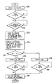
- Fig. 16 shows a fifth embodiment of the present invention in the form of the cap member and its related structure.
- a suction pump 20 is coupled at the suction port 20a with a first through hole 10a of the cap member 10 by way of the tube 11, and at the discharge port 20b with a used-ink tank 23 of an ink cartridge 22 by way of a tube 70.
- An ink tank 24 contained in the cartridge 22 is connected to the print head 10 by way of a tube 5.
- the cap member 10 is further provided with a second through hole 10b, and is coupled with an air open valve 72 by way of a tube 71.
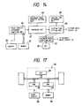
- a control circuit 73 is provided for executing a sequence of print recovery process steps, and is arranged as shown in Fig. 17.
- the control circuit 73 is composed of a microcomputer 84 including a CPU 81, a ROM 82 and a RAM 83, a clock circuit 85, and a memory 86 for storing time data representative of times of pushing of the recovery button 27.
- the microcomputer 84 is programmed so as to execute a sequence of operations as given below.
- the recovery button 27 which is provided on an operating panel of the printer chassis, is pushed, the position detector 18 produces a signal.
- the control circuit sends a signal to the solenoid drive circuit 28 (Fig. 16).
- the drive circuit 28 drives the solenoid 12 to press the cap member 10 against the print head 1.
- the control circuit sends a signal to the pump drive circuit 29 to operate the suction pump 20 for a preset time. Further, it sends a signal to the valve drive circuit 74, which intermittently opens and closes the air open valve 72 when a long suction time is completed.
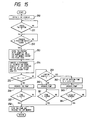
- Fig. 18 is a functional block diagram showing a model of the function to be realized by the microcomputer 84.
- the circuit is composed of time setting unit 91, comparing unit 92, suction time setting unit 93, solenoid drive unit 94, and valve drive directing unit 95.
- the time difference computing unit 90 computes a time difference ⁇ T between time data as stored in the memory 86 and the time of the present pushing of the recovery switch 27.
- the reference time setting unit 91 stores a reference time T0 to determine a type of printing defect.
- the comparing unit 92 compares the time difference ⁇ T derived from the time difference computing unit 90 with the reference time T0.
- the suction time setting unit 93 selects a suction time T S long enough to wash away paper particles and dust or a suction time T L long enough to remove air bubbles on the basis of the result of the comparison.
- the solenoid drive unit 94 energizes the solenoid 12 by a signal from the position detector 18, and de-energizes the same when the suction is completed.
- the valve drive directing unit 95 sends a signal to intermittently open and close the air open valve 72 when the suction of the suction time T L is completed, and the cap member 10 is separated from the print head 1.
- the users pushes the recovery button 27, which is provided on the chassis of the printer (step 270). Then, the carriage 4 is moved toward the cap member 10 under control of a carriage control circuit (not shown). The carriage 4 faces the cap member 10. At this time, the position detector 18 produces a signal (step 271). In response to the signal, the microcomputer 84 stores time data from the clock circuit 85 in the memory 86, and then sends a signal to the solenoid drive circuit 28 to energize the solenoid 12 (step 272). As a result, the cap member 10 hermetically closes the nozzle face 1a of the print head 1.
- the present pushing of the button is the first pushing after power on. Accordingly, the CPU determines that the time difference ⁇ T is longer than the reference time T0 (step 274).
- the computer 84 issues a signal to the pump drive circuit 29, thereby to operate the suction pump 20, and then closes the air open valve 72, whereby a negative pressure is generated in the nozzle receiving chamber 17 of the cap member 10 (step 275).
- the negative pressure acts on the nozzle face 1a to extract ink through the nozzle openings.
- step 276 the microcomputer 84 stops the operation of the pump 20 and opens the valve 72, and at the same time de-energizes the solenoid 12 to separate the cap member 10 from the print head 1 (step 277).
- the suction time is short, the pressure in the cap member 10 is relatively high (Fig. 20, waveforms 1). Accordingly, if the pump 20 is stopped, no impact will be applied to the meniscus of the nozzle.
- a printing defect occurs again after a relatively short time of approximately ten and several minutes from the previous pushing of the button 27.
- the user pushes the button 27 again (step 270).
- the carriage 4 is moved and reaches the position of the cap member 10, and the position detector 18 produces a signal (step 271).
- the microcomputer 84 stores time data l2 from the clock circuit 85 in the memory 86, and sends a signal to the solenoid drive circuit 28.
- the cap member 10 is pressed against the nozzle openings of the print head 1 (step 272).
- the reference time T0 is the time that elapses until the nozzles get clogged by foreign material, such as paper particles and dust, when the printer is operated in an ordinary printing mode, usually five to ten hours.
- the computer 84 selects the suction time T L longer than the suction time T S necessary for removing the foreign material.
- the computer When the nozzle face 1a of the print head 1 is hermetically closed by the cap member 10, the computer operates the pump 20 and closes the valve 72 to apply a negative pressure to the nozzle receiving chamber 17 of the cap member 10 (step 278).
- the negative pressure acting on the nozzle face 1a ink is discharged from the ink flow path through the nozzle openings into the nozzle receiving chamber. Together with the discharged ink, the air bubbles are attracted toward the nozzle openings and discharged from the nozzles.
- the microcomputer 84 sends a signal to the valve drive circuit 74, thereby to open and close the valve 72 plural times (step 280).
- a pressure in the nozzle receiving chamber 17 of the cap member 10 gradually rises (Fig. 20, waveforms II).
- the microcomputer 84 stops the operation of the pump 20, opens the valve 72, and separates the cap member 10 from the nozzle openings (step 277).
- the inner pressure within the cap member 10 which has gradually dropped, due to the long ink suction time, by pressure ⁇ P relative to the inner pressure at the time of paper particles removal, is gradually increased. Then, the pump 20 is stopped. Therefore, the suction operation can be stopped without applying an impact to the meniscus of the nozzle, and the next printing operation can be started reliably.
- the carriage 4 retracts to the position of the cap member 10 and the position detector 18 produces a signal.
- the microcomputer 84 stores the time data t3, which is received from the clock circuit 85, in the memory 86, and then sends a signal to the solenoid drive circuit 28.
- the solenoid 12 is energized to make the cap member 10 contact with the print head 1 (step 272).
- the time of operating the pump 20 is short, and hence the pressure in the cap member 10 is relatively high. Therefore, if the pump 20 is stopped, little adverse effects are placed on the meniscus of the nozzle.
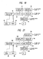
- Fig. 21 shows a sixth embodiment in terms of the function to be realized by the microcomputer 84.
- the circuit is composed of time difference computing unit 100, reference time setting unit 101, comparing unit 102, suction time setting unit 103, suction time prolong unit 104, solenoid drive directing unit 105, and valve drive directing unit 106.
- the time difference computing unit 100 computes a time difference ⁇ T between the time data stored in the memory 86 and the time of the present pushing of the recovery switch 27.
- the reference time setting unit 101 stores a reference time T0 to determine a type of printing defect.
- the comparing unit 102 compares the time difference ⁇ T derived from the time difference computing unit 100 with the reference time T0.
- the suction time setting unit 103 selects a suction time T S long enough to remove air bubbles on the basis of the result of the comparison.
- the suction time prolong unit 104 increments the suction time by fixed time ⁇ T a every the N number of the pushings of the recovery button.
- the solenoid drive directing unit 105 energizes the solenoid 12 either directly or via solenoid drive circuit 28, by a signal from the position detector 18, and de-energizes the same when the suction is completed.
- the valve drive directing unit 106 sends a signal to intermittently open and close the air open valve 72 when the suction of the suction time T L is completed, and the cap member 10 is separated from the print head 1.
- the user pushes the recovery button 27, which is provided on the chassis of the printer (step 290). Then, the carriage 4 is moved toward the cap member 10 under control of a carriage control circuit (not shown). The carriage 4 faces the cap member 10. At this time, the position detector 18 produces a signal (step 291). In response to the signal, the microcomputer 84 stores time data from the clock circuit 85 in the memory 86, and then sends a signal to the solenoid drive circuit 28 to energize the solenoid 12 (step 292). As a result, the cap member 10 hermetically closes the nozzle face 1a of the print head 1.
- the present pushing of the button is the first pushing after power on. Accordingly, the CPU determines that the time difference ⁇ T is longer than the reference time T0 (step 294).
- the computer 84 issues a signal to the pump drive circuit 29, thereby to operate the suction pump 20, and then closes the air open valve 72, whereby a negative pressure is generated in the nozzle receiving chamber 17 of the cap member 10 (step 295).
- the negative pressure acts on the nozzle face 1a to extract ink through the nozzle openings.
- step 296 the microcomputer 84 stops the operation of the pump 20 and opens the valve 72, and at the same time de-energizes the solenoid 12 to separate the cap member 10 from the print head 1 (step 297).
- the suction time is short, the pressure in the cap member 10 is relatively high (Fig. 23, waveforms I).
- the print head 1 is operable within the print region, and starts to operate again.
- a printing defect occurs again after a relatively short time of approximately ten and several minutes from the previous pushing of the button 27.
- the user pushes the button 27 again (step 290).
- the carriage 4 is moved and reaches the position of the cap member 10, and the position detector 18 produces a signal (step 291).
- the microcomputer 84 stores time data 12 from the clock circuit 85 in the memory 86, and sends a signal to the solenoid drive circuit 28.
- the cap member 10 is pressed against the nozzle openings of the print head 1 (step 292).
- it compares the difference time with the reference time T0 (step 294).
- the microcomputer 84 stops the operation of the pump 20, opens the valve 72, and separates the cap member 10 from the nozzle openings (step 297; Fig. 23, waveforms II).
- the microcomputer 84 opens and closes the valve 72 several times, to increase the pressure within the cap member 10 (step 301). Then, it stops the pump 20, opens the valve 72, and separates the print head 1 from the cap member 10 (step 297; Fig. 23, waveforms III).
- the suction time for the bubble removal is incremented by time ⁇ T ⁇ N every N number of pushings to be T L + ⁇ T ⁇ N (step 302).
- the present defect found is a heavy printing defect requiring frequent pushings of the recovery button, it can be cured by incrementing the amount sof the ink to be sucked. Further, the drop of the inner pressure of the cap member 10, which is caused by the long time suction, is relieved, thereby protecting the meniscus of the nozzles from the impact applied thereto. In this respect, reliable performance of the printer is ensured.
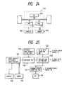
- Fig. 24 shows a seventh embodiment of the present invention in the form of an arrangement of the control circuit 73 .
- the control circuit 73 is composed of a microcomputer 113 including a CPU 110, a ROM 111 and a RAM 112, a counter 114 for counting a print quantity, such as the number of printed characters, the number of lines, and an amount of paper feed, and a memory 115 for storing data of the counted print quantity derived from the counter 114 when the recovery button 27 is pushed. It is programmed so as to execute a sequence of operations as given below. When the recovery button 27, which is provided on an operating panel of the printer chassis, is pushed, the position detector 18 shown in Fig. 16 produces a signal.
- the control circuit sends a signal to the solenoid drive circuit 28.
- the drive circuit 28 drives the solenoid 12 to press the cap member 10 against the print head 1, and sends a signal to the pump drive circuit 29 to operate the suction pump 20 for a preset time. Further, it sends a signal to the valve drive circuit 74, which intermittently opens and closes the air open valve 72 when a long suction time is completed.
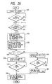
- Fig. 25 is a functional block diagram showing a model of the function to be realized by the microcomputer 113.
- the circuit is composed of print quantity difference computing unit 117, reference print quantity setting unit 118, comparing unit 119, suction time setting unit 120, solenoid drive directing unit 121, and valve drive directing unit 122.
- the print quantity difference computing unit 117 computes a print quantity difference ⁇ L between print quantity data stored in the memory 115 and data output from the counter 114 when the recovery button 27 is pushed.
- the reference print quantity setting unit 118 stores a reference print quantity L0 to determine a type of printing defect.
- the comparing unit 119 compares the print quantity difference data from the print quantity difference computing unit 117 with the reference print quantity L0.
- the suction time setting unit 120 selects a suction time T S long enough to wash away paper particles and dust or a suction time T L long enough to remove air bubbles on the basis of the result of the comparison.
- the solenoid drive directing unit 121 energizes directly or via solenoid drive circuit, 28 the solenoid 12 by a signal from the position detector 18, and de-energizes the same when the suction is completed.
- the valve drive directing unit 122 sends a signal to intermittently open and close the air open valve 72 when the suction of the suction time T L or more is completed, and the cap member 10 is separated from the print head 1.
- the microcomputer 113 Upon start of a printing operation, the microcomputer 113 causes the counter 114 to count the print quantity (step 310). During the printing operation, if a printing defect is found, the user pushes the recovery button 27, which is provided on the chassis of the printer (step 311). Then, the carriage 4 is moved toward the cap member 10 under control of a carriage control circuit (not shown). The carriage 4 faces the cap member 10. At this time, the position detector 18 produces a signal (step 312). In response to the signal, the microcomputer 113 stores the print quantity l1 of the counter 114 in the memory 115, and at the same time sends a signal to the solenoid drive circuit 28 to energize the solenoid 12.
- the cap member 10 hermetically closes the nozzle face 1a of the print head 1 (step 313).
- the present pushing of the button is the first pushing after power on. Accordingly, the CPU determines that the print quantity difference ⁇ L is larger than the reference print quantity L0 (step 315).
- the computer 113 issues a signal to the pump drive circuit 29, thereby to operate the section pump 20, and then closes the valve 72, whereby a negative, pressure is generated in the nozzle receiving chamber 17 of the cap member 10 (step 316).
- the negative pressure acts on the nozzle face 1a to extract ink through the nozzle openings. With the flow of the ink paper particles and dust stuck to the nozzle openings are washed away.
- step 317 the microcomputer 113 stops the operation of the pump 20 and opens the valve 74, and at the same time de-energizes the solenoid 12 to separate the cap member 10 from the print head 1 (step 318). Under this condition, the print head 1 is operable in a print region and starts the printing operation again.
- a printing defect occurs again after a relatively short time of ten and several lines from the previous pushing of the button 27.
- the user pushes the button 27 again (step 311).
- the carriage 4 is moved and reaches the position of the cap member 10, and the position detector 18 produces a signal (step 312).
- the microcomputer 113 stores print quantity data l2 from the counter 114 in the memory 115, and sends a signal to the solenoid drive circuit 28.
- the cap member 10 is pressed against the nozzle openings of the print head 1 (step 313).
- the microcomputer 113 computes a print quantity difference between the print quantity data l2 and the previous print quantity l1 stored in the memory 115, viz.
- ⁇ L l2 - l1 (step 314). Then, it compares the difference print quantity with the reference print quantity L0 (step 315).
- the microcomputer 113 selects the suction time T L , which is longer than the suction time T S for removing the paper particles and dust (step 319).
- the computer When the nozzle face 1a of the print head 1 is hermetically closed by the cap member 10, the computer operates the pump 20 and closes the valve 72, to apply a negative pressure to the nozzle receiving chamber 17 of the cap member 10 (step 319).
- the negative pressure acting on the nozzle face 1a ink is discharged from the ink flow path through the nozzle openings into the nozzle receiving chamber. Together with the discharged ink, the air bubbles are attracted toward the nozzle openings and discharged outside from the nozzles.
- the microcomputer 84 sends a signal to the valve drive circuit 74, thereby to open and close the valve 72 plural times (step 321). As a result, a pressure in the nozzle receiving chamber 17 of the cap member 10 gradually rises (step 321). Then, the microcomputer 84 stops the operation of the pump 20, opens the valve 72, de-energizes the solenoid 12, and separates the cap member 10 from the nozzle openings (step 318). Under this condition, the carriage 4 is movable within the print region (step 318).
- the carriage 4 retracts to the position of the cap member 10 and the position detector 18 produces a signal.
- the microcomputer 113 stores the print quantity data l3 of the counter 114 in the memory 115, and then sends a signal to the solenoid drive circuit 28.
- the solenoid 12 is energized to make the cap member 10 contact with the print head 1 (step 313).
- Fig. 27 shows an eighth embodiment in the form of the function to be realized by the microcomputer.
- the circuit is composed of print quantity difference computing unit 130, reference print quantity setting unit 131, comparing unit 132, suction time setting unit 133, suction time extending unit 134, solenoid drive directing unit 135, and valve drive directing unit 136.
- the print quantity difference computing unit 130 computes a print quantity difference ⁇ L between print quantity data stored in the memory 115 and data output from the counter 114 when the recovery button 27 is pushed.
- the reference print quantity setting unit 131 stores a reference print quantity L0 to determine the type of printing defect.
- the comparing unit 132 compares the print quantity difference data from the print quantity difference computing unit 130 with the reference print quantity L0.
- the suction time setting unit 133 selects a suction time T S long enough to wash away paper particles and dust or a suction time T L long enough to remove air bubbles on the basis of the result of the comparison.
- the suction time extending unit 136 increments the suction time by fixed time ⁇ T a every the N number of pushings of the recovery button.
- the solenoid drive unit 135 energizes the solenoid 12 by a signal from the position detector 18, and de-energizes the same when the suction is completed.
- the valve drive directing unit 136 sends a signal to intermittently open and close the air open valve 72 when the suction of the suction time T L or more is completed, and the cap member 10 is separated from the print head 1.
- the microcomputer 113 Upon starting of a printing operation, the microcomputer 113 causes the counter 114 to count the print quantity (step 330). During the printing operation, if a printing defect is found, the user pushes the recovery button 27, which is provided on the chassis of the printer (step 331). Then, the carriage 4 is moved toward the cap member 10 under control of a carriage control circuit (not shown). The carriage 4 faces the cap member 10. At this time, the position detector 18 produces a signal (step 332).
- the microcomputer 113 fetches from the counter 114 the print quantity l1 at the instant that the recovery button 27 generates a signal, and stores the print quantity l1 of the counter 114 in the memory 115, and at the same time sends a signal to the solenoid drive circuit 28 to energize the solenoid 12.
- the cap member 10 hermetically closes the nozzle face 1a of the print head 1 (step 333).
- the microcomputer 113 fetches from the computer 114 the print quantity l1 until the recovery button 27 produces a signal. Then, the microcomputer 113 computes a print quantity difference between the print quantity l1 and a print quantity 10 obtained in the previous pushing of the recovery button 27, viz.
- ⁇ L l1 - l0 (step 334), and compares the different print quantity with the reference print quantity L0 (step 335). Then, the computer 113 issues a signal to the pump drive circuit 29, thereby to operate the suction pump 20, and then closes the valve 72, whereby a negative pressure is generated in the nozzle receiving chamber 17 of the cap member 10 (step 336). The negative pressure acts on the nozzle face 1a to extract ink through the nozzle openings. With the flow of the ink, paper particles and dust stuck to the nozzle openings are washed away.
- step 337) the microcomputer 113 stops the operation of the pump 20 and opens the valve 74, and at the same time de-energizes the solenoid 12 to separate the cap member 10 from the print head 1 (step 338). Under this condition, the print head 1 is operable in a print region and starts the printing operation again.
- a printing defect occurs again after a relatively short time of several tens lines from the previous pushing of the button 27.
- the user pushes the button 27 again (step 331).
- the carriage 4 is moved and reaches the position of the cap member 10, and the position detector 18 produces a signal (step 332).
- the microcomputer 113 stores print quantity data l2 from the counter 114 in the memory 57, and sends a signal to the solenoid drive circuit 28.
- the cap member 10 is pressed against the nozzle openings of the print head 1 (step 333).
- it compares the difference print quantity with the reference print quantity L0 (step 335).
- the computer When the nozzle face 1a of the print head 1 is hermetically closed by the cap member 10, the computer operates the pump 20 and closes the valve 72, to apply a negative pressure to the nozzle receiving chamber 17 of the cap member 10 (step 339).
- the negative pressure acting on the nozzle face 1a ink is discharged from the ink flow path through the nozzle openings into the nozzle receiving chamber. Together with the discharged ink, the air bubbles are attracted toward the nozzle openings and discharged outside from the nozzles.
- the microcomputer 84 sends a signal to the valve drive circuit 74, thereby to open and close the valve 72 plural times (step 321). As a result, a pressure in the nozzle receiving chamber 17 of the cap member 10 gradually rises (step 321). Then, the microcomputer 84 stops the operation of the pump 20, opens the valve 72, de-energizes the solenoid 12, and separates the cap member 10 from the nozzle openings (step 338). Under this condition, the carriage 4 is movable within the print region (step 338) and the print operation starts again.
- step 331 When the recovery button 27 is pushed again, with a small print quantity of several tens after the previous pushing of the button 27 (step 331), the carriage 4 retracts to the position of the cap member 10 and the position detector 18 produces a signal. At this time (step 332), the microcomputer 113 stores the print quantity data 12 of the counter 114 in the memory 115, and then sends a signal to the solenoid drive circuit 28. By the signal, the solenoid 12 is energized to make the cap member 10 contact with the print head 1 (step 333).
- the printing defect due to the air bubbles will occur again within a very short time, e.g. , several lines to ten and several lines. If such printing defect occurs and the user pushes the recovery button 27 (step 331), the carriage 4 is moved to the position of the cap member 10 and the position detector 18 produces an output signal (step 332). At this time, the microcomputer 33 stores the print quantity l3 of the counter 114 in the memory 115, and sends a signal to the solenoid drive circuit 28. Then, the cap member 10 is pressed against the nozzle openings of the print head 1 (step 333).
- the microcomputer After the incremented suction time T L + ⁇ T a elapses (step 345), the microcomputer opens the valve 72 plural times (step 342). When the inner pressure in the cap member 72 has been increased, the microcomputer stops, opens the valve 72, and separates the cap member 10 from the print head 1 (step 338).
- the suction time for the bubble removal is incremented by time ⁇ T ⁇ N every N number of pushings to be T L + ⁇ T ⁇ N (step 262).
- the print found is a heavy printing defect requiring frequent pushings of the recovery button, it can be cured by incrementing the amount of the ink to be sucked.
- the pressure within the cap member which has been considerably reduced as the result of a long time of operation of the pump, is gradually increased up to atmospheric pressure. This feature allows the cap member to be removed without disturbing the meniscus of the nozzles.
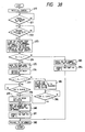
- Fig. 29 is a perspective view showing a ninth embodiment of the present invention in the form of a structure including a cap member and its related structure, which is suitable for curing printing defects caused by such a brush.
- reference numeral 140 designates a brush mechanism which is located outside the print region, or adjacent to the cap member 10, in this instance.
- a belt 143 with linear members as brushes 144 and 144 fixed thereto, is strained between paired rollers 141 and 142, which are driven by a drive mechanism (not shown).
- the tips of the brushes 144 and 144 contact the nozzle openings of the print head 1 to thus wipe the nozzle openings and the portion in the vicinity thereof.
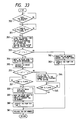
- Fig. 30 is a block and schematic diagram showing the arrangement of a printer containing an ink supply flow system, an ink suction flow system operating in a print recovery mode, and a control system for print recovery.
- the brush mechanism 140 is driven by a wiper drive circuit 146, which receives a signal from a control circuit 145 (described in more detail below).
- a suction pump 20, constructed as already described referring to Fig. 2 is coupled at the suction port 20a via a first through hole 10a of the cap member 10 by way of the tube 70, and at the discharge port 20b with a used-ink tank 23 of an ink cartridge 22 by way of a tube 70.
- An ink tank 24 contained in the cartridge 22 is connected for ink supply to the print head 10 via a tube 5.
- the cap member 10 is moved to and retracted from the front face 1a of the print head 1 by the solenoid 12, which is driven by a signal from the solenoid drive circuit 28.
- Fig. 31 shows an embodiment of the control circuit for executing a sequence of print recovery process steps, which is arranged as shown in Fig. 4.
- the control circuit 26 is composed of a microcomputer 151 including a CPU 148, a ROM 149 and a RAM 150, a clock circuit 152, and a memory 153 for storing time data representative of the time of pushing of the recovery button 27.
- the control circuit 26 is programmed so as to execute a sequence of operations as given below.
- the recovery button 27 which is provided on an operating panel of the printer chassis, is pushed, the position detector 18 produces a signal.
- the control circuit 145 sends a signal to the solenoid drive circuit 28 (Fig.30) .
- the drive circuit 28 drives the solenoid 12 to press the cap member 10 against the print head 1.
- the control circuit sends a signal to the pump drive circuit 29 to operate the suction pump 20 for a preset time.
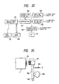
- Fig. 32 is a functional block diagram showing the functions to be realized by the microcomputer 151.
- the circuit is composed of a time difference computing unit 155, reference time setting unit 156, comparing unit 157, wiping time setting unit 158, suction time setting unit 159, and solenoid drive directing unit 160.
- the time difference computing unit 155 computes a time difference ⁇ T between time data stored in the memory 153 and time data generated from the clock circuit 152 when the recovery button 27 is pushed.
- the reference time setting unit 156 stores a reference time T0 to determine a type of printing defect.
- the comparing unit 157 the time difference ⁇ T derived from the time difference computing unit 155 with the reference time T0.
- the wiping time setting unit 158 sets a brush mechanism drive time T d necessary for removing paper particles and dust, on the basis of the comparison result.
- the suction time setting unit 159 selects an ink suction time T c after the wiping or a suction time T L long enough to remove air bubbles.
- the solenoid drive directing unit 160 In response to the position detector 18, the solenoid drive directing unit 160 generates a signal that directly or via solenoid drive circuit 28 moves the print head 1 toward the brush mechanism 140 or the cap member 10, and such that when the print head 1 is positioned in front of the cap member 10, it energizes the solenoid 12 or de-energizes the same when the suction is completed.
- the microcomputer 151 moves the print head toward the brush 140, which is located separated by a fixed distance from the position detector 18, and places it to face the brush mechanism 140 (step 354). Then, it sends a signal to the wiper drive circuit 146 to operate the brush mechanism 140 (step 355).
- the belt 143 is driven by the drive mechanism (not shown), so that the brushes 144 and 144 move in contact with the nozzle openings of the print head 1 to wipe away paper particles and dust at the nozzle openings.
- a preset time T b the duration of the first brushing operation in this case
- the brush mechanism 140 is stopped (step 358).
- the computer 151 issues a signal to the solenoid drive circuit 28, and energizes the solenoid 12 to hermetically close the nozzle face 1a of the print head 1 with the cap member 10 (step 359).
- the microcomputer 151 sends a signal to the pump drive circuit 29 to operate the suction pump 20.
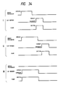
- the microcomputer 151 stops the operation of the pump 20 (step 360), and at the same time de-energizes the solenoid 12 to separate the cap member 10 from the print head (step 361). Under this condition, the print head 1 is operated in a print region and starts the printing operation again (Fig. 34, waveforms I).
- a printing defect occurs again after a relatively short time of ten and several minutes to one hour from the previous pushing of the button 27.
- the user pushes the button 27 again (step 350).
- the carriage 4 is moved and reaches the position of the cap member 10, and the position detector 18 produces a signal (step 351).
- the microcomputer 151 sends a signal to the solenoid drive circuit 28 to press the cap member 10 against the nozzle front faces of the print head 1 (step 362). Then, it operates the pump 20 to apply a negative pressure into the nozzle receiving chamber 17 of the cap member 10 (step 363).
- the negative pressure acts on the nozzle front face 1a, and extracts jet from the ink flow path through the nozzle openings. Together with the discharge of the ink, the bubbles contained in the ink flow path is discharged through the nozzle openings to exterior.
- the solenoid 12 is de-energized to remove the cap member 10 from the nozzle openings, and the carriage 4 is placed to be movable to the print region (step 361).
- the microcomputer 351 executes the process from the step 350 to step 361 to remove the foreign material and to recover the printer from its abnormal state, (Fig. 34, waveform III).
- time T0′ elapses, which is longer than the reference time T0, but is very close to the reference time T0.
- the button 27 is pushed again (step 350).
- the cap member 10 moves to and faces the print head 1, and the position detector 18 produces a signal (step 351).
- the comparison result shows that the reference time T0 is shorter than the time difference computed (step 353).
- the microcomputer 151 moves the print head 1 toward the brush mechanism 140, which is located separated by a fixed distance from the position detector 18, and places it to face the brush mechanism 140 (step 354). Then, the microcomputer 151 sends a signal to the wiper drive circuit 146 to operate the brush mechanism 140 (step 355). As a result, the belt 143 is driven by the drive mechanism (not shown), so that the brushes 144 and 144 move in contact with the nozzle openings of the print head 1, to wipe away paper particles and dust at the nozzle openings. In the case now discussed, the time interval between the pushings of the button 27 is very close to the reference time T0 (step 356).
- the brush mechanism 140 is stopped (step 358).
- the steps 359 to 361 are executed, and the print recovery operation ends. In this way, the paper particles and pieces can be removed completely (Fig. 34, waveforms II).
- the brushing time T d is incremented.
- the brushes are mounted on the belt.
- the brushes is moved in contact with the nozzle face of the printer head with the rotation of the belt.
- an eccentric cam 164 is coupled with a rotating drive mechanism (not shown).
- An arm 166 which is swingable about a shaft 163, is held in contact with the eccentric cam 164 by means of a spring 165.
- a brush 167 is mounted on the free end of the arm 166.
- the cam 164 rotates and accordingly the brush 167 reciprocatively contacts the nozzle face 1a of the printer head 1.
- the brush may be fixed at a position where it is in contact with the nozzle face of the printer head, and under this condition the print head is moved with the reciprocative motion of the carriage.
- Fig. 36 shows a tenth embodiment of the present invention in the form of an arrangement of the control circuit 145.
- the control circuit 145 is composed a microcomputer 173 including a CPU 170, a ROM 171 and a RAM 172, a counter 174 for counting a print quantity, such as the number of printed characters, the number of lines, and an amount of paper feed, and a memory 175 for storing data of the counted print quantity derived from the counter 174 when the recovery button 27 is pushed. It is programmed so as to execute a sequence of operations as given below.
- the recovery button 27 which is provided on an operating panel of the printer chassis, is pushed, the position detector 18 produces a signal.
- the control circuit sends a signal to the solenoid drive circuit 28.
- the drive circuit 28 drives the solenoid 12 to press the cap member 10 against the print head 1. Then, it sends a signal to the pump drive circuit 29 to operate the suction pump 20 for a preset time, or it sends a signal to the wiper drive circuit 146 to drive the brush mechanism 140.
- Fig. 37 is a functional block diagram showing a model of the function to be realized by the microcomputer 173.
- the circuit is composed of print quantity difference computing unit 177, reference print quantity setting unit 178, comparing unit 179, wiping time setting unit 180, suction time setting unit 181, and solenoid drive directing unit 182.
- the print quantity difference computing unit 177 computes a print quantity difference between print quantity data stored in the memory 175 and data output from the counter 174 when the recovery button 27 is pushed.
- the reference print quantity setting unit 178 stores a reference print quantity L0 to determine the type of printing defect.
- the comparing unit 179 compares the print quantity difference data from the print quantity difference computing unit 177 with the reference print quantity L0.
- the wiping time setting unit 180 is for setting a wiping time T d necessary for removing paper particles and dust, on the basis of the comparison result.
- the suction time setting unit 181 selects an ink suction time T c after the wiping or a suction time T L long enough to remove air bubbles on the basis of the result of the comparison.
- the solenoid drive directing unit 182 generates a signal that moves directly or via solenoid drive circuit 28 the print head 1 toward the brush mechanism 140 of the cap member 10, and that, when the print head 1 is positioned in front of the cap member 10, energizes the solenoid 12 or de-energizes the same when the suction operation is completed.
- the microcomputer 173 Upon start of a printing operation, the microcomputer 173 causes the counter 174 to count the print quantity (step 370). During the printing operation, if a printing defect is found, the user pushes the recovery button 27 provided on the chassis of the printer (step 371). Then, the carriage 4 is moved toward the cap member 10 under control of a carriage control circuit (not shown). The carriage 4 faces the cap member 10. At this time, the position detector 18 produces a signal (step 372). In response to the signal, the microcomputer 173 fetches from the counter 174 the print quantity l1, and stores it in the memory 175. Then, the microcomputer 173 computes a print quantity difference between the print quantity l1 and a print quantity l0 obtained in the previous pushing of the recovery button 27, viz.
- step 373 When the computed time data is compared with the reference time data T0 and the former is smaller than the latter (step 374), the microcomputer 151 moves the print head 1 toward the brush mechanism 140, which is located separated by a fixed distance from the position detector 18, and places it to face the brush mechanism 140 (step 375). Then, it sends a signal to the wiper drive circuit 146, to operate the brush mechanism 140 (step 376). As a result, the belt 143 is driven by the drive mechanism (not shown), so that the brushes 144 and 144 move in contact with the nozzle openings of the print head 1, to wipe away paper particles and dust at the nozzle openings.
- step 377 After a preset time, or time T b because of the first brushing operation in this case (step 377), elapses (step 378), the brush mechanism 140 is stopped (step 379). Then, the computer 173 moves the print head 1 to the cap member 10, and issues a signal to the solenoid drive circuit 28, and energizes the solenoid 12 to hermetically close the nozzle face 1a of the print head 1 with the cap member 10 (step 380). The microcomputer 151 sends a signal to the pump drive circuit 29 to operate the suction pump 20. As a consequence, the negative pressure acts on the nozzle face 1a to extract ink through the nozzle openings. With the flow of the ink, paper particles and dust adhering to the nozzle openings are washed away.
- the microcomputer 151 stops the operation of the pump 20 (step 381), and at the same time de-energizes the solenoid 12 to separate the cap member 10 from the print head 1 (step 382). Under the condition, the print head 1 is operable in a print region and starts the printing operation again.
- a printing defect occurs again after a relatively small print quantity of several tens lines from the previous pushing of the button 27.
- the user pushes the button 27 again (step 371).
- the carriage 4 is moved and reaches the position of the cap member 10, and the position detector 18 produces a signal (step 372).
- the result of the comparison shows that the reference time T0 is shorter than the difference time (step 374).
- the microcomputer 173 sends a signal to the solenoid drive circuit 28 to press the cap member 10 against the nozzle front faces of the print head 1 (step 383). Then, it operates the pump 20 to apply a negative pressure in the nozzle receiving chamber 17 of the cap member 10. The negative pressure acts on the nozzle front face 1a, and extracts jet from the ink flow path through the nozzle openings. Together with the discharge of the ink, the bubbles contained in the ink flow path is discharged through the nozzle openings to exterior.
- the solenoid 12 is de-energized to remove the cap member 10 from the nozzle openings, and the carriage 4 is placed to be movable to the print region (step 382).
- the print quantity l2 of the previous pushing of the button 27 grows to be in excess of the reference print quantity L0.
- the recovery button 27 is pushed.
- the microcomputer 173 executes the process from the step 371 to step 382, to remove the foreign material and to recover the printer from its abnormal state.
- a print quantity L3 is obtained, which is larger than the reference print quantity L0, but is smaller than the reference print quantity L0′ which is slightly larger than that L0.
- the button 27 is pushed again (step 371).
- the cap member 10 moves to and faces the print head 1, and the position detector 18 produces a signal (step 372).
- the comparison result shows that the reference print quantity L0 is shorter than the print quantity difference computed (step 374).
- the microcomputer 173 moves the print head 1 toward the brush mechanism 140, which is located separated by a fixed distance from the position detector 18, and places it to face the brush mechanism 140 (step 375). Then, it sends a signal to the wiper drive circuit 146, to operate the brush mechanism 140 (step 376).
- the belt 143 is driven by the drive mechanism (not shown), so that the brushes 144 and 144 move in contact with the nozzle openings of the print head 1 to wipe away paper particles and dust at the nozzle openings.
- the print quantity interval between the pushings of the button 27 is very close the reference print quantity L0 (step 377).
- the brush mechanism 140 is stopped (step 379).
- the steps 380 to 382 are executed, and the print recovery operation ends. In this way, the paper particles and pieces can be removed completely.
- the microcomputer in the control circuit determines the brushing time of each brushing and the number of brushings on the basis of the time intervals between the pushings of the recovery button 27. Therefore, the printer can be quickly recovered from light printing defects which frequently occur due to paper particles and dust accumulating on the nozzles openings during the printing operation. For heavy printing defects due to paper pieces caused by jamming, the brushing time is extended to reduce the recovery time of the printer and the number of pushings of the recovery button.
- the present invention is applicable to printers in which the ink tank and the print head are assembled in a single unit, and the unit is mounted on the carriage.
Applications Claiming Priority (6)
| Application Number | Priority Date | Filing Date | Title |
|---|---|---|---|
| JP28839089 | 1989-11-06 | ||
| JP288390/89 | 1989-11-06 | ||
| JP30285389 | 1989-11-21 | ||
| JP302853/89 | 1989-11-21 | ||
| JP13898090 | 1990-05-29 | ||
| JP138980/90 | 1990-05-29 |
Publications (3)
| Publication Number | Publication Date |
|---|---|
| EP0427202A2 true EP0427202A2 (de) | 1991-05-15 |
| EP0427202A3 EP0427202A3 (en) | 1991-07-24 |
| EP0427202B1 EP0427202B1 (de) | 1996-07-10 |
Family
ID=27317778
Family Applications (1)
| Application Number | Title | Priority Date | Filing Date |
|---|---|---|---|
| EP90121220A Expired - Lifetime EP0427202B1 (de) | 1989-11-06 | 1990-11-06 | Farbstrahlaufzeichnungsvorrichtung |
Country Status (6)
| Country | Link |
|---|---|
| US (3) | US5153614A (de) |
| EP (1) | EP0427202B1 (de) |
| JP (1) | JP2946725B2 (de) |
| DE (1) | DE69027739T2 (de) |
| HK (1) | HK124697A (de) |
| SG (1) | SG47065A1 (de) |
Cited By (12)
| Publication number | Priority date | Publication date | Assignee | Title |
|---|---|---|---|---|
| EP0525988A2 (de) * | 1991-07-17 | 1993-02-03 | Canon Kabushiki Kaisha | Farbstrahlaufzeichnungsgerät |
| US5248999A (en) * | 1990-10-12 | 1993-09-28 | Seiko Epson Corporation | Ink jet printing apparatus having ink purging feature |
| EP0608104A2 (de) * | 1993-01-19 | 1994-07-27 | Canon Kabushiki Kaisha | Abfallfarbeüberwachung für Tintenstrahlaufzeichnungsvorrichtung |
| WO1996004141A1 (en) * | 1994-07-29 | 1996-02-15 | Mit Modular Ink Technology I Stockholm Ab | Printing arrangement |
| EP0698495A2 (de) * | 1994-08-26 | 1996-02-28 | Canon Kabushiki Kaisha | Tintenstrahlaufzeichnungsvorrichtung und Rückgewinnungsverfahren dafür |
| EP0972644A1 (de) * | 1998-07-15 | 2000-01-19 | Seiko Epson Corporation | Tintenstrahldrucker und Inbetriebsstellungsverfahren dafür |
| DE19849567A1 (de) * | 1998-10-27 | 2000-05-04 | Tally Computerdrucker Gmbh | Tintendrucker mit einer Wechselkartusche für Tintenflüssigkeit |
| US6227646B1 (en) * | 1991-10-02 | 2001-05-08 | Canon Kabushiki Kaisha | Ink jet recording apparatus |
| DE10105352C1 (de) * | 2001-02-05 | 2002-08-08 | Tally Computerdrucker Gmbh | Tintendrucker mit einer Absaugstation |
| WO2002064375A1 (de) * | 2001-02-14 | 2002-08-22 | Zünd Systemtechnik Ag | Verfahren und vorrichtung zum befüllen von druckköpfen |
| EP1464499A2 (de) * | 2003-03-24 | 2004-10-06 | Toshiba Tec Kabushiki Kaisha | Reinigungsvorrichtung für Tintenstrahlkopf und Tintenstrahldruckvorrichtung |
| CN101138907B (zh) * | 2006-09-08 | 2011-03-30 | 佳能株式会社 | 记录设备、废液收集系统、液体容器和喷墨记录方法 |
Families Citing this family (39)
| Publication number | Priority date | Publication date | Assignee | Title |
|---|---|---|---|---|
| US6145956A (en) * | 1990-04-11 | 2000-11-14 | Canon Kabushiki Kaisha | Discharge recovery method and apparatus for an ink jet recording head |
| SG46707A1 (en) * | 1991-05-15 | 1998-02-20 | Seiko Epson Corp | Ink jet type recording apparatus and method of cleaning a recording head |
| JPH04355153A (ja) * | 1991-05-31 | 1992-12-09 | Canon Inc | インクジェット記録装置 |
| US5812165A (en) * | 1991-08-29 | 1998-09-22 | Hewlett-Packard Company | Leak resistant ink-jet pen |
| JP3159225B2 (ja) * | 1992-06-26 | 2001-04-23 | セイコーエプソン株式会社 | インクジェット記録装置 |
| EP0802058B1 (de) * | 1993-02-02 | 1999-05-06 | Seiko Epson Corporation | Verfahren zum Befüllen von Tintendurchgängen mit Tinte |
| JP3233175B2 (ja) * | 1993-03-11 | 2001-11-26 | セイコーエプソン株式会社 | インクジェット式記録装置 |
| EP0765751B1 (de) * | 1993-03-11 | 2000-01-19 | Seiko Epson Corporation | Tintenstrahlaufzeichnungsgerät |
| US5559539A (en) * | 1993-10-12 | 1996-09-24 | Dataproducts Corporation | Ink jet recording apparatus having self aligning print head cleaning system and method of operating the print head cleaning system |
| ATE209571T1 (de) * | 1993-12-27 | 2001-12-15 | Canon Kk | Tintenstrahlgerät und verfahren dieses zu steuern |
| JP3259748B2 (ja) * | 1994-03-31 | 2002-02-25 | セイコーエプソン株式会社 | インクジェット式記録装置 |
| US5627572A (en) * | 1994-10-24 | 1997-05-06 | Lexmark International, Inc. | Programmable head type detection and maintenance system |
| KR0132809B1 (ko) * | 1995-03-14 | 1998-04-14 | 김광호 | 잉크 제트 프린터에서의 잉크흡입량 조절방법 |
| JP3270664B2 (ja) * | 1995-08-30 | 2002-04-02 | キヤノン株式会社 | インクジェット記録装置及びインクジェット記録装置の回復方法 |
| US5946008A (en) * | 1995-12-19 | 1999-08-31 | Seiko Epson Corporation | Ink-jet printer for improving the freedom of movement of the carriage during a cleaning operation |
| JP3480478B2 (ja) * | 1996-01-16 | 2003-12-22 | セイコーエプソン株式会社 | インクジェット式記録装置 |
| US5980034A (en) * | 1996-03-11 | 1999-11-09 | Videojet Systems International, Inc. | Cross flow nozzle system for an ink jet printer |
| WO1999022941A1 (fr) * | 1997-11-05 | 1999-05-14 | Seiko Epson Corporation | Imprimante et son procede de commande |
| US6045206A (en) * | 1998-02-09 | 2000-04-04 | Pitney Bowes Inc. | Ink-jet printer having variable maintenance algorithm |
| EP0976568B1 (de) * | 1998-07-29 | 2005-10-19 | Seiko Epson Corporation | Druckvorrichtung, sein Rücksetzverfahren und Speichermedium |
| US6637853B1 (en) | 1999-07-01 | 2003-10-28 | Lexmark International, Inc. | Faulty nozzle detection in an ink jet printer by printing test patterns and scanning with a fixed optical sensor |
| US6215557B1 (en) | 1999-07-01 | 2001-04-10 | Lexmark International, Inc. | Entry of missing nozzle information in an ink jet printer |
| JP2001162784A (ja) * | 1999-12-13 | 2001-06-19 | Canon Inc | インクジェット記録装置および記録方法 |
| DE10109761C2 (de) * | 2001-02-28 | 2003-06-18 | Tally Computerdrucker Gmbh | Verfahren und Einrichtung zum Befüllen eines Tintenzuführungssystems in einem Tintendrucker |
| JP3874680B2 (ja) * | 2002-03-19 | 2007-01-31 | 三菱電機株式会社 | 対物レンズ駆動装置 |
| CN1286645C (zh) * | 2003-02-28 | 2006-11-29 | 精工爱普生株式会社 | 液滴喷出装置及液滴喷出头的喷出异常检测、判断方法 |
| JP3867792B2 (ja) * | 2003-03-27 | 2007-01-10 | セイコーエプソン株式会社 | 液滴吐出装置及びインクジェットプリンタ |
| JP3867794B2 (ja) * | 2003-04-16 | 2007-01-10 | セイコーエプソン株式会社 | 液滴吐出装置、インクジェットプリンタ及びヘッド異常検出・判定方法 |
| JP3867788B2 (ja) * | 2003-03-12 | 2007-01-10 | セイコーエプソン株式会社 | 液滴吐出装置およびインクジェットプリンタ |
| JP3867791B2 (ja) * | 2003-03-27 | 2007-01-10 | セイコーエプソン株式会社 | 液滴吐出装置、及びインクジェットプリンタ |
| JP3867793B2 (ja) * | 2003-03-28 | 2007-01-10 | セイコーエプソン株式会社 | 液滴吐出装置、インクジェットプリンタ及び液滴吐出ヘッドの吐出異常検出方法 |
| JP3867789B2 (ja) * | 2003-03-20 | 2007-01-10 | セイコーエプソン株式会社 | 液滴吐出装置、インクジェットプリンタ、及び液滴吐出ヘッドの吐出異常判定方法 |
| JP2005103792A (ja) * | 2003-09-29 | 2005-04-21 | Brother Ind Ltd | インクジェット記録装置 |
| JP2007118547A (ja) * | 2005-10-31 | 2007-05-17 | Brother Ind Ltd | インクジェットプリンタ |
| JP4944631B2 (ja) * | 2007-02-02 | 2012-06-06 | キヤノン株式会社 | インクジェット記録装置および回復処理方法 |
| JP2009154406A (ja) * | 2007-12-27 | 2009-07-16 | Brother Ind Ltd | インクジェット記録装置 |
| JP5333091B2 (ja) * | 2009-09-09 | 2013-11-06 | 株式会社リコー | 画像形成装置、画像形成システム、画像形成プログラムおよびそれを記録した記録媒体 |
| JP2013052644A (ja) * | 2011-09-06 | 2013-03-21 | Shima Seiki Mfg Ltd | インクジェットプリントシステムのノズルクリーニング方法とインクジェットプリントシステム |
| CN114166743B (zh) * | 2019-09-29 | 2023-06-30 | 安徽万磁电子股份有限公司 | 一种磁瓦表面缺陷检查系统的磁瓦凹面的缺陷判定方法 |
Citations (5)
| Publication number | Priority date | Publication date | Assignee | Title |
|---|---|---|---|---|
| US4362572A (en) * | 1981-06-25 | 1982-12-07 | Burroughs Corporation | Method and apparatus for cleaning ink jet printer heads |
| US4577203A (en) * | 1981-09-30 | 1986-03-18 | Epson Corporation | Ink jet recording apparatus |
| DE3611333A1 (de) * | 1985-04-05 | 1986-10-16 | Canon K.K., Tokio/Tokyo | Fluessigkeitsstrahl-aufzeichnungsgeraet und in dem geraet verwendete saug-regeneriereinrichtung |
| US4692777A (en) * | 1983-11-08 | 1987-09-08 | Canon Kabushiki Kaisha | Means for restoring liquid discharge function of a liquid jet recorder |
| JPS63115755A (ja) * | 1986-11-04 | 1988-05-20 | Canon Inc | インクジエツト回復装置 |
Family Cites Families (4)
| Publication number | Priority date | Publication date | Assignee | Title |
|---|---|---|---|---|
| JPS59190858A (ja) * | 1983-04-15 | 1984-10-29 | Canon Inc | インクジエツトプリンタ |
| JPS61249759A (ja) * | 1985-04-30 | 1986-11-06 | Canon Inc | 印字装置 |
| US4926196A (en) * | 1986-12-25 | 1990-05-15 | Canon Kabushiki Kaisha | Ink jet printer |
| JP2728436B2 (ja) * | 1988-06-23 | 1998-03-18 | キヤノン株式会社 | インクジェット記録装置 |
-
1990
- 1990-10-19 JP JP28135090A patent/JP2946725B2/ja not_active Expired - Fee Related
- 1990-11-05 US US07/608,858 patent/US5153614A/en not_active Expired - Lifetime
- 1990-11-06 DE DE69027739T patent/DE69027739T2/de not_active Expired - Fee Related
- 1990-11-06 EP EP90121220A patent/EP0427202B1/de not_active Expired - Lifetime
- 1990-11-06 SG SG1996005259A patent/SG47065A1/en unknown
-
1992
- 1992-08-18 US US07/913,636 patent/US5296876A/en not_active Expired - Lifetime
-
1993
- 1993-03-15 US US08/032,186 patent/US5379061A/en not_active Expired - Lifetime
-
1997
- 1997-06-26 HK HK124697A patent/HK124697A/xx not_active IP Right Cessation
Patent Citations (5)
| Publication number | Priority date | Publication date | Assignee | Title |
|---|---|---|---|---|
| US4362572A (en) * | 1981-06-25 | 1982-12-07 | Burroughs Corporation | Method and apparatus for cleaning ink jet printer heads |
| US4577203A (en) * | 1981-09-30 | 1986-03-18 | Epson Corporation | Ink jet recording apparatus |
| US4692777A (en) * | 1983-11-08 | 1987-09-08 | Canon Kabushiki Kaisha | Means for restoring liquid discharge function of a liquid jet recorder |
| DE3611333A1 (de) * | 1985-04-05 | 1986-10-16 | Canon K.K., Tokio/Tokyo | Fluessigkeitsstrahl-aufzeichnungsgeraet und in dem geraet verwendete saug-regeneriereinrichtung |
| JPS63115755A (ja) * | 1986-11-04 | 1988-05-20 | Canon Inc | インクジエツト回復装置 |
Non-Patent Citations (1)
| Title |
|---|
| PATENT ABSTRACTS OF JAPAN, vol. 12, no. 360 (M-476)[3207], 27th September 1988; & JP-A-63 115 755 (CANON INC.) 20-05-1988 * |
Cited By (23)
| Publication number | Priority date | Publication date | Assignee | Title |
|---|---|---|---|---|
| US5248999A (en) * | 1990-10-12 | 1993-09-28 | Seiko Epson Corporation | Ink jet printing apparatus having ink purging feature |
| EP0525988A3 (de) * | 1991-07-17 | 1993-02-24 | Canon Kabushiki Kaisha | Farbstrahlaufzeichnungsgerät |
| EP0525988A2 (de) * | 1991-07-17 | 1993-02-03 | Canon Kabushiki Kaisha | Farbstrahlaufzeichnungsgerät |
| US6227646B1 (en) * | 1991-10-02 | 2001-05-08 | Canon Kabushiki Kaisha | Ink jet recording apparatus |
| US5764253A (en) * | 1993-01-19 | 1998-06-09 | Canon Kabushiki Kaisha | Ink jet recording apparatus provided with means for calculating waste ink amount, and information processing system provided with such an ink jet recording apparatus |
| EP0608104A2 (de) * | 1993-01-19 | 1994-07-27 | Canon Kabushiki Kaisha | Abfallfarbeüberwachung für Tintenstrahlaufzeichnungsvorrichtung |
| EP0608104A3 (de) * | 1993-01-19 | 1995-03-22 | Canon Kk | Abfallfarbeüberwachung für Tintenstrahlaufzeichnungsvorrichtung. |
| AU678188B2 (en) * | 1993-01-19 | 1997-05-22 | Canon Kabushiki Kaisha | Ink jet recording apparatus provided with means for calculating waste ink amount, and information processing system provided with such an ink jet recording apparatus |
| WO1996004141A1 (en) * | 1994-07-29 | 1996-02-15 | Mit Modular Ink Technology I Stockholm Ab | Printing arrangement |
| US5805180A (en) * | 1994-08-26 | 1998-09-08 | Canon Kabushiki Kaisha | Ink jet recording apparatus which performs suction recovery with a cap and method for same |
| EP0698495A2 (de) * | 1994-08-26 | 1996-02-28 | Canon Kabushiki Kaisha | Tintenstrahlaufzeichnungsvorrichtung und Rückgewinnungsverfahren dafür |
| US6340217B1 (en) | 1994-08-26 | 2002-01-22 | Canon Kabushiki Kaisha | Ink jet recording apparatus and recovery method thereof |
| EP0698495A3 (de) * | 1994-08-26 | 1997-12-10 | Canon Kabushiki Kaisha | Tintenstrahlaufzeichnungsvorrichtung und Rückgewinnungsverfahren dafür |
| EP0972644A1 (de) * | 1998-07-15 | 2000-01-19 | Seiko Epson Corporation | Tintenstrahldrucker und Inbetriebsstellungsverfahren dafür |
| US6364448B2 (en) | 1998-07-15 | 2002-04-02 | Seiko Epson Corporation | Ink jet printer and ink priming method therefor |
| DE19849567B4 (de) * | 1998-10-27 | 2004-02-12 | Tally Computerdrucker Gmbh | Tintendrucker mit einer Wechselkartusche für Tintenflüssigkeit |
| DE19849567A1 (de) * | 1998-10-27 | 2000-05-04 | Tally Computerdrucker Gmbh | Tintendrucker mit einer Wechselkartusche für Tintenflüssigkeit |
| DE10105352C1 (de) * | 2001-02-05 | 2002-08-08 | Tally Computerdrucker Gmbh | Tintendrucker mit einer Absaugstation |
| WO2002064375A1 (de) * | 2001-02-14 | 2002-08-22 | Zünd Systemtechnik Ag | Verfahren und vorrichtung zum befüllen von druckköpfen |
| EP1464499A2 (de) * | 2003-03-24 | 2004-10-06 | Toshiba Tec Kabushiki Kaisha | Reinigungsvorrichtung für Tintenstrahlkopf und Tintenstrahldruckvorrichtung |
| EP1464499A3 (de) * | 2003-03-24 | 2005-08-10 | Toshiba Tec Kabushiki Kaisha | Reinigungsvorrichtung für Tintenstrahlkopf und Tintenstrahldruckvorrichtung |
| CN101138907B (zh) * | 2006-09-08 | 2011-03-30 | 佳能株式会社 | 记录设备、废液收集系统、液体容器和喷墨记录方法 |
| US8523315B2 (en) | 2006-09-08 | 2013-09-03 | Canon Kabushiki Kaisha | Recording device with a storage section including an absorption member to store a waste liquid collected from a recording head according to the operation of a pump which receives information from a processing unit which retains information about waste liquid retention and pump operation times |
Also Published As
| Publication number | Publication date |
|---|---|
| US5379061A (en) | 1995-01-03 |
| US5296876A (en) | 1994-03-22 |
| JP2946725B2 (ja) | 1999-09-06 |
| HK124697A (en) | 1997-09-12 |
| US5153614A (en) | 1992-10-06 |
| DE69027739T2 (de) | 1996-12-05 |
| JPH0473159A (ja) | 1992-03-09 |
| SG47065A1 (en) | 1998-03-20 |
| DE69027739D1 (de) | 1996-08-14 |
| EP0427202B1 (de) | 1996-07-10 |
| EP0427202A3 (en) | 1991-07-24 |
Similar Documents
| Publication | Publication Date | Title |
|---|---|---|
| EP0427202B1 (de) | Farbstrahlaufzeichnungsvorrichtung | |
| US4967204A (en) | Method for ensuring stable operation of an ink jet recording apparatus | |
| EP0552472B1 (de) | Verfahren und Vorrichtung zur Ausstosswiederherstellung für Tintenstrahldrucker | |
| EP0674996B1 (de) | Abdeckverfahren für Farbstrahlaufzeichnungsvorrichtung | |
| JPH0519468B2 (de) | ||
| JP4009936B2 (ja) | インクジェット式記録装置 | |
| EP0836945B1 (de) | Tintenstrahlaufzeichnungsgerät | |
| JP3491662B2 (ja) | インクジェット式記録装置 | |
| JP3695502B2 (ja) | インクジェット式記録装置および同装置における記録ヘッドのクリーニング制御方法 | |
| JPH0957989A (ja) | インクジェット記録装置 | |
| JP4296605B2 (ja) | インクジェット記録装置 | |
| JP3757627B2 (ja) | インクジェット記録装置およびそのインク吸引処理方法 | |
| EP1050411A1 (de) | Tintenstrahlaufzeichnungsgerät | |
| JPH106531A (ja) | インクジェット記録装置 | |
| US5886715A (en) | Print head maintenance mechanism | |
| US7246877B2 (en) | Ink jet printing apparatus | |
| JPH04307256A (ja) | インクヘッド回復装置 | |
| JP2002137415A (ja) | インクジェット式記録装置のフラッシング方法及びインクジェット式記録装置 | |
| JP3794209B2 (ja) | インクジェット記録装置及びその回復処理方法 | |
| JP2805770B2 (ja) | インクジェット記録装置 | |
| JP2740228B2 (ja) | 液体噴射記録装置および該液体噴射記録装置の回復方法 | |
| JP4395916B2 (ja) | インクジェット記録装置 | |
| JP3064440B2 (ja) | インクジェット記録装置 | |
| JPH1029314A (ja) | インクジェットヘッドのキャップ手段 | |
| JPH06143554A (ja) | インクジェット記録装置 |
Legal Events
| Date | Code | Title | Description |
|---|---|---|---|
| PUAI | Public reference made under article 153(3) epc to a published international application that has entered the european phase |
Free format text: ORIGINAL CODE: 0009012 |
|
| AK | Designated contracting states |
Kind code of ref document: A2 Designated state(s): DE FR GB |
|
| PUAL | Search report despatched |
Free format text: ORIGINAL CODE: 0009013 |
|
| AK | Designated contracting states |
Kind code of ref document: A3 Designated state(s): DE FR GB |
|
| 17P | Request for examination filed |
Effective date: 19920122 |
|
| 17Q | First examination report despatched |
Effective date: 19931001 |
|
| GRAH | Despatch of communication of intention to grant a patent |
Free format text: ORIGINAL CODE: EPIDOS IGRA |
|
| GRAA | (expected) grant |
Free format text: ORIGINAL CODE: 0009210 |
|
| AK | Designated contracting states |
Kind code of ref document: B1 Designated state(s): DE FR GB |
|
| REF | Corresponds to: |
Ref document number: 69027739 Country of ref document: DE Date of ref document: 19960814 |
|
| ET | Fr: translation filed | ||
| PLBE | No opposition filed within time limit |
Free format text: ORIGINAL CODE: 0009261 |
|
| STAA | Information on the status of an ep patent application or granted ep patent |
Free format text: STATUS: NO OPPOSITION FILED WITHIN TIME LIMIT |
|
| 26N | No opposition filed | ||
| REG | Reference to a national code |
Ref country code: GB Ref legal event code: IF02 |
|
| PGFP | Annual fee paid to national office [announced via postgrant information from national office to epo] |
Ref country code: DE Payment date: 20071101 Year of fee payment: 18 |
|
| PGFP | Annual fee paid to national office [announced via postgrant information from national office to epo] |
Ref country code: GB Payment date: 20071031 Year of fee payment: 18 Ref country code: FR Payment date: 20071108 Year of fee payment: 18 |
|
| GBPC | Gb: european patent ceased through non-payment of renewal fee |
Effective date: 20081106 |
|
| REG | Reference to a national code |
Ref country code: FR Ref legal event code: ST Effective date: 20090731 |
|
| PG25 | Lapsed in a contracting state [announced via postgrant information from national office to epo] |
Ref country code: DE Free format text: LAPSE BECAUSE OF NON-PAYMENT OF DUE FEES Effective date: 20090603 |
|
| PG25 | Lapsed in a contracting state [announced via postgrant information from national office to epo] |
Ref country code: GB Free format text: LAPSE BECAUSE OF NON-PAYMENT OF DUE FEES Effective date: 20081106 |
|
| PG25 | Lapsed in a contracting state [announced via postgrant information from national office to epo] |
Ref country code: FR Free format text: LAPSE BECAUSE OF NON-PAYMENT OF DUE FEES Effective date: 20081130 |