EP0426008B1 - Fassadenkonstruktion - Google Patents
Fassadenkonstruktion Download PDFInfo
- Publication number
- EP0426008B1 EP0426008B1 EP90120484A EP90120484A EP0426008B1 EP 0426008 B1 EP0426008 B1 EP 0426008B1 EP 90120484 A EP90120484 A EP 90120484A EP 90120484 A EP90120484 A EP 90120484A EP 0426008 B1 EP0426008 B1 EP 0426008B1
- Authority
- EP
- European Patent Office
- Prior art keywords
- profiles
- structure according
- facade structure
- auxiliary
- facade
- Prior art date
- Legal status (The legal status is an assumption and is not a legal conclusion. Google has not performed a legal analysis and makes no representation as to the accuracy of the status listed.)
- Expired - Lifetime
Links
Images

Classifications
-
- E—FIXED CONSTRUCTIONS
- E06—DOORS, WINDOWS, SHUTTERS, OR ROLLER BLINDS IN GENERAL; LADDERS
- E06B—FIXED OR MOVABLE CLOSURES FOR OPENINGS IN BUILDINGS, VEHICLES, FENCES OR LIKE ENCLOSURES IN GENERAL, e.g. DOORS, WINDOWS, BLINDS, GATES
- E06B7/00—Special arrangements or measures in connection with doors or windows
- E06B7/14—Measures for draining-off condensed water or water leaking-in frame members for draining off condensation water, throats at the bottom of a sash
-
- E—FIXED CONSTRUCTIONS
- E04—BUILDING
- E04B—GENERAL BUILDING CONSTRUCTIONS; WALLS, e.g. PARTITIONS; ROOFS; FLOORS; CEILINGS; INSULATION OR OTHER PROTECTION OF BUILDINGS
- E04B2/00—Walls, e.g. partitions, for buildings; Wall construction with regard to insulation; Connections specially adapted to walls
- E04B2/88—Curtain walls
- E04B2/96—Curtain walls comprising panels attached to the structure through mullions or transoms
- E04B2/967—Details of the cross-section of the mullions or transoms
-
- E—FIXED CONSTRUCTIONS
- E06—DOORS, WINDOWS, SHUTTERS, OR ROLLER BLINDS IN GENERAL; LADDERS
- E06B—FIXED OR MOVABLE CLOSURES FOR OPENINGS IN BUILDINGS, VEHICLES, FENCES OR LIKE ENCLOSURES IN GENERAL, e.g. DOORS, WINDOWS, BLINDS, GATES
- E06B3/00—Window sashes, door leaves, or like elements for closing wall or like openings; Layout of fixed or moving closures, e.g. windows in wall or like openings; Features of rigidly-mounted outer frames relating to the mounting of wing frames
- E06B3/54—Fixing of glass panes or like plates
- E06B3/5427—Fixing of glass panes or like plates the panes mounted flush with the surrounding frame or with the surrounding panes
Definitions
- the invention relates to a facade construction with frameless insulating glazing (structural glazing) attached to facade profiles via load-bearing seals.
- a facade construction is known in which insulating glass panes are attached to facade profiles via a load-bearing seal.
- An auxiliary profile protrudes into the space formed between the edge regions of adjacent insulating glass panes, the outer end of the auxiliary profile being arranged at a distance from the edge region of the insulating glass pane.
- the free end of the auxiliary profile has grooves open to the outside for receiving a folding seal. The folding seal thus bridges part of the space between the edge areas of the adjacent insulating glass panes.
- the remaining free spaces between the auxiliary profile and the respective edge areas of the insulating glass panes are sealed by first having this intermediate space on the weather side with a silicone compound and then directly on the room side with a stop compound which is in direct contact with the sealing of the insulating glass panes.
- the entire space between the edge regions of the adjacent insulating glass panes is thus sealed or closed in the manner of a weather seal.
- the disadvantage of this known construction is that a stop compound and a silicone compound are arranged directly after the sealing of the insulating glass panes. Despite the silicone mass on the weather side, it cannot be prevented that in the area between Stop and silicone mass as well as the sealing of the insulating glass panes, moisture penetrates and accumulates there. The area of the sealing of the insulating glass panes is thus constantly surrounded by a moisture-containing area, which moisture cannot be removed due to the lack of ventilation. As a result, there is a risk that, due to differences in vapor pressure, moisture will get through the sealing of the insulating glass pane into the space between the individual insulating glass panes, which is not desirable.
- GB-A-2 196 047 discloses a facade construction in which insulating glass panes are held on facade profiles by means of a prestressed holder with the interposition of a seal. While a free end of the holder is fixed to the facade profiles, the other free end of the holder encompasses the inner pane of the insulating glazing in its edge area, the free end of this holder reaching as far as the sealing of the insulating glass panes.
- the region of the free end of the holder facing insulating glazing is designed such that a seal-like profile can be clipped into the holder, which overlaps the outer panes of adjacent insulating glazing.
- a mechanical holder for insulating glass panes on a facade is known from EP-A-0 130 438.
- the mechanical holding means engage in appropriately designed spacers of the insulating glazing and are mechanically attached to the facade.
- the space between the edges of adjacent insulating glazing can be filled in sections with a filler material, and openings can additionally be provided in the weather seal between the free edges of the outer glass panes.
- the solution according to the invention advantageously leads to an essentially watertight intermediate space or glass rebate space in which the insulating glass back or insulating glass pane edges remain optimally ventilated.
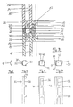
- FIG. 1 to 3 show facade profiles 10 to which frameless glazings 14 are fastened via load-bearing seals 12, while spacers 13 maintain the distance between the insulating glazings 14 and the facade profiles 10.
- Each insulating glazing 14 consists of an outer pane 16 and an inner pane 18. Between the panes 16 and 18, spacers 26 are arranged, which are arranged offset inwards from the edge regions 22 of the panes 16 and 18. Seals are arranged in the space between the spacers 26 and the edge regions of the panes 16 and 18 lying outside them, which form load-bearing insulating glass backs 30. In addition, inner seals 56 are arranged between the opposing end faces of the inner panes 18, while the space between the inner seals 56, the inner load-bearing Seals 12 and the adjacent facade profiles 10, a backfill material 58 is arranged.
- auxiliary profiles 20 or 21 or 32 or 60 are arranged between the mutually opposite edge regions 22 of the outer panes 16 of the glazing units 14. These auxiliary profiles bridge the distance between the mutually opposite edge regions of adjacent outer panes 16 and keep the space 24 between opposite seals 30 of the glazings 14 free, i.e. There is no material in the room, nor is there any filling material.
- auxiliary profiles of all embodiments are designed to be resilient or flexible perpendicular to their longitudinal axis in order to be able to accommodate movements of the individual insulating glazings against one another.
- a weather seal 28 is provided on the outside of the auxiliary profiles 32, which may consist of silicone.
- the auxiliary profiles 32 consist of a plastic on which silicone does not adhere, or an interruption in adhesion is provided between the auxiliary profiles 32 and the weather seal 28, which can be formed, for example, by a polyethylene film 29 inserted between the auxiliary profile 32 and the weather seal 28.
- auxiliary profiles of all embodiments can consist of polyethylene.
- the auxiliary profiles 72 can have the embodiment shown in cross section.
- the auxiliary profiles 32 are U-shaped in cross section.
- the U-legs 34 of the auxiliary profiles 32 are formed at regular intervals with recesses 36, while the U-web 38 is zigzag or meandering.
- These auxiliary profiles 32 rest with their U-legs 34 on mutually opposite supporting backs 30 of the insulating glazing 14.
- FIG. 6 shows another embodiment of an auxiliary profile 40, which is designed as a box profile in the form of two mutually inverted U-profiles, as shown in FIG. 5. These box profiles rest with their leg surfaces 42 on the opposing supporting back 30 of the insulating glazing 14. Recesses 36 are also formed in the leg surfaces 42 at regular intervals.
- the auxiliary profiles 40 designed as box profiles are each surrounded by two profile strips 44, 46 with a U-shaped cross section.
- the distances between the U-legs 48 and 50 of the profile strips 44, 46 are selected to be of different sizes, so that the profile strips 44, 46 can move relative to one another transversely to their longitudinal axis.
- the profile strips 44, 46 have interruptions 52 in their U-webs 54 at regular intervals.
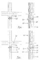
- openings 64 are formed in auxiliary profiles 60, which are arranged in vertical joints between adjacent glazings 14 in the outer wall 62 serve to compensate for vapor pressure differences and for drainage.
- Curved plastic tubes 66 are arranged in the openings 64 and are inserted with their openings pointing downwards.
- Cross seals 68 are provided under the openings 64 in the vertical joints behind the auxiliary profiles 60.
- openings 64 are provided both above and below the transverse seals 68.
- openings 70 are provided in the auxiliary profiles 60, which are arranged in horizontal joints between adjacent glazings 14, which also serve to compensate for vapor pressure differences and for drainage.
- These openings 70 are advantageously arranged in or near the intersection area of the auxiliary profiles 60, an arrangement being preferred which is arranged lower than the upper edge of a lower glazing, wherein a curved tube with a downward opening is also inserted in each of these openings 70 is.
Landscapes
- Engineering & Computer Science (AREA)
- Civil Engineering (AREA)
- Structural Engineering (AREA)
- Architecture (AREA)
- Physics & Mathematics (AREA)
- Electromagnetism (AREA)
- Load-Bearing And Curtain Walls (AREA)
Applications Claiming Priority (4)
| Application Number | Priority Date | Filing Date | Title |
|---|---|---|---|
| DE3936114 | 1989-10-30 | ||
| DE3936114 | 1989-10-30 | ||
| DE3939619 | 1989-11-30 | ||
| DE3939619A DE3939619C1 (pt) | 1989-10-30 | 1989-11-30 |
Publications (2)
| Publication Number | Publication Date |
|---|---|
| EP0426008A1 EP0426008A1 (de) | 1991-05-08 |
| EP0426008B1 true EP0426008B1 (de) | 1994-07-20 |
Family
ID=25886576
Family Applications (1)
| Application Number | Title | Priority Date | Filing Date |
|---|---|---|---|
| EP90120484A Expired - Lifetime EP0426008B1 (de) | 1989-10-30 | 1990-10-25 | Fassadenkonstruktion |
Country Status (2)
| Country | Link |
|---|---|
| EP (1) | EP0426008B1 (pt) |
| DE (2) | DE3939619C1 (pt) |
Families Citing this family (10)
| Publication number | Priority date | Publication date | Assignee | Title |
|---|---|---|---|---|
| DE59101574D1 (de) * | 1991-01-10 | 1994-06-09 | Gartner & Co J | Fassadenkonstruktion. |
| IT1253665B (it) * | 1991-12-20 | 1995-08-22 | Facciata strutturale continua per edifici ad elementi indipendenti | |
| DE4204799C3 (de) * | 1992-02-18 | 1998-03-26 | Wicona Bausysteme Gmbh | Fassadenkonstruktion |
| DE4218351A1 (de) * | 1992-06-04 | 1993-12-16 | Mero Raumstruktur Gmbh & Co | Abdichtsystem für Ein- bzw. Abdeckungselemente von Gebäudedächern und-fassaden |
| FR2711725B1 (fr) * | 1993-10-21 | 1996-01-19 | Saint Gobain Vitrage Int | Moyen de jointoiement pour vitrages. |
| DE4343964C2 (de) * | 1993-12-22 | 2002-07-18 | Seele Gmbh | Gebäudekonstruktion als Glasfassade oder Glasdach |
| DE19649942C2 (de) * | 1996-12-03 | 2000-02-17 | Wicona Bausysteme Gmbh | Aus Pfosten und Riegeln in Form von Hohlprofilen aufgebaute Rahmenkonstruktion |
| DE59900893D1 (de) * | 1998-05-13 | 2002-04-04 | Schulz Harald | Fassadenkonstruktion |
| KR101344734B1 (ko) * | 2013-03-27 | 2013-12-24 | 주식회사 중일 | 단열재가 내장된 커튼월 |
| CN106352462A (zh) * | 2016-09-30 | 2017-01-25 | 南京理工大学 | 一种带有净化除尘功能的箱式通风双层玻璃幕墙及其净化除尘方法 |
Family Cites Families (6)
| Publication number | Priority date | Publication date | Assignee | Title |
|---|---|---|---|---|
| US4552790A (en) * | 1983-06-30 | 1985-11-12 | Francis Geoffrey V | Structural spacer glazing with connecting spacer device |
| DE8333529U1 (de) * | 1983-11-22 | 1989-02-02 | Straub, Theodor, 8857 Gottmannshofen | Fassade |
| DE3425740C3 (de) * | 1984-07-12 | 1996-06-13 | Gartner & Co J | Distanzprofilkörper für die rahmenlose Befestigung von Verglasungselementen an Gebäuden |
| DE3540385A1 (de) * | 1985-11-14 | 1987-05-21 | Eltreva Ag | Fassadenkonstruktion aus metallprofilen |
| DE3631566A1 (de) * | 1986-09-17 | 1988-04-14 | Eltreva Ag | Fassadenkonstruktion |
| DE3703650C2 (de) * | 1987-02-06 | 1996-01-04 | Baukonstruktionen Ges Gbk | Glasfassade bzw. Glasdach mit Drainage für zwischen den Falzen der Glasfelder verbleibende hohle Falzräume |
-
1989
- 1989-11-30 DE DE3939619A patent/DE3939619C1/de not_active Expired - Lifetime
-
1990
- 1990-10-25 DE DE59006501T patent/DE59006501D1/de not_active Expired - Fee Related
- 1990-10-25 EP EP90120484A patent/EP0426008B1/de not_active Expired - Lifetime
Also Published As
| Publication number | Publication date |
|---|---|
| EP0426008A1 (de) | 1991-05-08 |
| DE59006501D1 (de) | 1994-08-25 |
| DE3939619C1 (pt) | 1991-06-27 |
Similar Documents
| Publication | Publication Date | Title |
|---|---|---|
| DE69432603T2 (de) | System zur errichtung einer mauer aus blöcken und komponenten dafür | |
| DE69419772T2 (de) | Verglasungssystem für gebäude | |
| DE2746365B2 (de) | Vorhangwand | |
| DE2811604A1 (de) | Rahmen | |
| EP0426008B1 (de) | Fassadenkonstruktion | |
| AT396497B (de) | Gebäudeaussenverkleidung, insbesondere fassade, mit plattenförmigen bauelementen | |
| EP0018006B1 (de) | Isolation für Dach oder Wand eines Gebäudes und Verfahren zum Montieren derselben | |
| DE3815140C2 (de) | Blendrahmen zur Bildung einer Fugenschalung zwecks Verbindung von einzelnen Glasbauelementen | |
| AT392311B (de) | Rahmenkonstruktion in pfosten-riegel-bauweise, insbesondere fuer fassaden, daecher, fensterwaende od. dgl. | |
| DE29607069U1 (de) | Isolierglasscheibe mit fotovoltaischem Element | |
| DE2907267C2 (de) | Vorgefertigtes Deckenauflagerelement | |
| EP0169340A2 (de) | Fassade oder Dach in einer Metall-Glas-Ausführung | |
| DE202014010902U1 (de) | Isolierelement für Fassaden- oder Lichtdachkonstruktionen | |
| EP0374891B1 (de) | Gebäudewand aus Glasbauelementen | |
| DE4343964C2 (de) | Gebäudekonstruktion als Glasfassade oder Glasdach | |
| EP0495150B1 (de) | Fassadenkonstruktion | |
| DE2553934A1 (de) | Wandverkleidung | |
| DE4100578C2 (de) | Fassadenkonstruktion | |
| AT393703B (de) | Rahmenkonstruktion in pfosten-riegel-bauweise, insbesondere fuer fassaden od. dgl. | |
| EP0100558B1 (de) | Kantenschutz für Isolierglas | |
| DE3141482A1 (de) | "glasscheibe mit umlaufendem kantenschutz aus dauerelastischem kunststoff" | |
| DE2411082A1 (de) | Grossflaechenprofil-verglasung aus durchsichtigem glas | |
| DE10015838A1 (de) | Zusatzelement für Isolierglasscheiben | |
| DE3343264C1 (de) | Türrahmen | |
| DE2824519C3 (de) | Verwendung einer wärme- und/oder schalldämmenden Isolierglasscheibe |
Legal Events
| Date | Code | Title | Description |
|---|---|---|---|
| PUAI | Public reference made under article 153(3) epc to a published international application that has entered the european phase |
Free format text: ORIGINAL CODE: 0009012 |
|
| AK | Designated contracting states |
Kind code of ref document: A1 Designated state(s): DE FR GB NL |
|
| 17P | Request for examination filed |
Effective date: 19910612 |
|
| 17Q | First examination report despatched |
Effective date: 19920522 |
|
| GRAA | (expected) grant |
Free format text: ORIGINAL CODE: 0009210 |
|
| AK | Designated contracting states |
Kind code of ref document: B1 Designated state(s): DE FR GB NL |
|
| REF | Corresponds to: |
Ref document number: 59006501 Country of ref document: DE Date of ref document: 19940825 |
|
| GBT | Gb: translation of ep patent filed (gb section 77(6)(a)/1977) |
Effective date: 19940804 |
|
| ET | Fr: translation filed | ||
| PLBE | No opposition filed within time limit |
Free format text: ORIGINAL CODE: 0009261 |
|
| STAA | Information on the status of an ep patent application or granted ep patent |
Free format text: STATUS: NO OPPOSITION FILED WITHIN TIME LIMIT |
|
| 26N | No opposition filed | ||
| PGFP | Annual fee paid to national office [announced via postgrant information from national office to epo] |
Ref country code: NL Payment date: 19981030 Year of fee payment: 9 Ref country code: GB Payment date: 19981030 Year of fee payment: 9 |
|
| PG25 | Lapsed in a contracting state [announced via postgrant information from national office to epo] |
Ref country code: GB Free format text: LAPSE BECAUSE OF NON-PAYMENT OF DUE FEES Effective date: 19991025 |
|
| PGFP | Annual fee paid to national office [announced via postgrant information from national office to epo] |
Ref country code: FR Payment date: 19991028 Year of fee payment: 10 |
|
| PG25 | Lapsed in a contracting state [announced via postgrant information from national office to epo] |
Ref country code: NL Free format text: LAPSE BECAUSE OF NON-PAYMENT OF DUE FEES Effective date: 20000501 |
|
| GBPC | Gb: european patent ceased through non-payment of renewal fee |
Effective date: 19991025 |
|
| NLV4 | Nl: lapsed or anulled due to non-payment of the annual fee |
Effective date: 20000501 |
|
| PGFP | Annual fee paid to national office [announced via postgrant information from national office to epo] |
Ref country code: DE Payment date: 20001220 Year of fee payment: 11 |
|
| PG25 | Lapsed in a contracting state [announced via postgrant information from national office to epo] |
Ref country code: FR Free format text: LAPSE BECAUSE OF NON-PAYMENT OF DUE FEES Effective date: 20010629 |
|
| REG | Reference to a national code |
Ref country code: FR Ref legal event code: ST |
|
| PG25 | Lapsed in a contracting state [announced via postgrant information from national office to epo] |
Ref country code: DE Free format text: LAPSE BECAUSE OF NON-PAYMENT OF DUE FEES Effective date: 20020702 |