EP0423774B1 - Anlage zur Beschichtung bahnförmiger Trägermaterialien oder zur Herstellung trägerloser Bahnen - Google Patents
Anlage zur Beschichtung bahnförmiger Trägermaterialien oder zur Herstellung trägerloser Bahnen Download PDFInfo
- Publication number
- EP0423774B1 EP0423774B1 EP90119939A EP90119939A EP0423774B1 EP 0423774 B1 EP0423774 B1 EP 0423774B1 EP 90119939 A EP90119939 A EP 90119939A EP 90119939 A EP90119939 A EP 90119939A EP 0423774 B1 EP0423774 B1 EP 0423774B1
- Authority
- EP
- European Patent Office
- Prior art keywords
- installation according
- coating
- water
- carrier
- cooled
- Prior art date
- Legal status (The legal status is an assumption and is not a legal conclusion. Google has not performed a legal analysis and makes no representation as to the accuracy of the status listed.)
- Expired - Lifetime
Links
Images


Classifications
-
- B—PERFORMING OPERATIONS; TRANSPORTING
- B32—LAYERED PRODUCTS
- B32B—LAYERED PRODUCTS, i.e. PRODUCTS BUILT-UP OF STRATA OF FLAT OR NON-FLAT, e.g. CELLULAR OR HONEYCOMB, FORM
- B32B37/00—Methods or apparatus for laminating, e.g. by curing or by ultrasonic bonding
- B32B37/14—Methods or apparatus for laminating, e.g. by curing or by ultrasonic bonding characterised by the properties of the layers
- B32B37/24—Methods or apparatus for laminating, e.g. by curing or by ultrasonic bonding characterised by the properties of the layers with at least one layer not being coherent before laminating, e.g. made up from granular material sprinkled onto a substrate
-
- B—PERFORMING OPERATIONS; TRANSPORTING
- B05—SPRAYING OR ATOMISING IN GENERAL; APPLYING FLUENT MATERIALS TO SURFACES, IN GENERAL
- B05C—APPARATUS FOR APPLYING FLUENT MATERIALS TO SURFACES, IN GENERAL
- B05C19/00—Apparatus specially adapted for applying particulate materials to surfaces
- B05C19/04—Apparatus specially adapted for applying particulate materials to surfaces the particulate material being projected, poured or allowed to flow onto the surface of the work
-
- B—PERFORMING OPERATIONS; TRANSPORTING
- B05—SPRAYING OR ATOMISING IN GENERAL; APPLYING FLUENT MATERIALS TO SURFACES, IN GENERAL
- B05C—APPARATUS FOR APPLYING FLUENT MATERIALS TO SURFACES, IN GENERAL
- B05C5/00—Apparatus in which liquid or other fluent material is projected, poured or allowed to flow on to the surface of the work
- B05C5/001—Apparatus in which liquid or other fluent material is projected, poured or allowed to flow on to the surface of the work incorporating means for heating or cooling the liquid or other fluent material
-
- B—PERFORMING OPERATIONS; TRANSPORTING
- B05—SPRAYING OR ATOMISING IN GENERAL; APPLYING FLUENT MATERIALS TO SURFACES, IN GENERAL
- B05C—APPARATUS FOR APPLYING FLUENT MATERIALS TO SURFACES, IN GENERAL
- B05C5/00—Apparatus in which liquid or other fluent material is projected, poured or allowed to flow on to the surface of the work
- B05C5/02—Apparatus in which liquid or other fluent material is projected, poured or allowed to flow on to the surface of the work the liquid or other fluent material being discharged through an outlet orifice by pressure, e.g. from an outlet device in contact or almost in contact, with the work
- B05C5/0254—Coating heads with slot-shaped outlet
-
- B—PERFORMING OPERATIONS; TRANSPORTING
- B05—SPRAYING OR ATOMISING IN GENERAL; APPLYING FLUENT MATERIALS TO SURFACES, IN GENERAL
- B05C—APPARATUS FOR APPLYING FLUENT MATERIALS TO SURFACES, IN GENERAL
- B05C9/00—Apparatus or plant for applying liquid or other fluent material to surfaces by means not covered by any preceding group, or in which the means of applying the liquid or other fluent material is not important
- B05C9/04—Apparatus or plant for applying liquid or other fluent material to surfaces by means not covered by any preceding group, or in which the means of applying the liquid or other fluent material is not important for applying liquid or other fluent material to opposite sides of the work
-
- B—PERFORMING OPERATIONS; TRANSPORTING
- B05—SPRAYING OR ATOMISING IN GENERAL; APPLYING FLUENT MATERIALS TO SURFACES, IN GENERAL
- B05C—APPARATUS FOR APPLYING FLUENT MATERIALS TO SURFACES, IN GENERAL
- B05C9/00—Apparatus or plant for applying liquid or other fluent material to surfaces by means not covered by any preceding group, or in which the means of applying the liquid or other fluent material is not important
- B05C9/06—Apparatus or plant for applying liquid or other fluent material to surfaces by means not covered by any preceding group, or in which the means of applying the liquid or other fluent material is not important for applying two different liquids or other fluent materials, or the same liquid or other fluent material twice, to the same side of the work
-
- B—PERFORMING OPERATIONS; TRANSPORTING
- B05—SPRAYING OR ATOMISING IN GENERAL; APPLYING FLUENT MATERIALS TO SURFACES, IN GENERAL
- B05C—APPARATUS FOR APPLYING FLUENT MATERIALS TO SURFACES, IN GENERAL
- B05C9/00—Apparatus or plant for applying liquid or other fluent material to surfaces by means not covered by any preceding group, or in which the means of applying the liquid or other fluent material is not important
- B05C9/08—Apparatus or plant for applying liquid or other fluent material to surfaces by means not covered by any preceding group, or in which the means of applying the liquid or other fluent material is not important for applying liquid or other fluent material and performing an auxiliary operation
- B05C9/12—Apparatus or plant for applying liquid or other fluent material to surfaces by means not covered by any preceding group, or in which the means of applying the liquid or other fluent material is not important for applying liquid or other fluent material and performing an auxiliary operation the auxiliary operation being performed after the application
-
- B—PERFORMING OPERATIONS; TRANSPORTING
- B29—WORKING OF PLASTICS; WORKING OF SUBSTANCES IN A PLASTIC STATE IN GENERAL
- B29C—SHAPING OR JOINING OF PLASTICS; SHAPING OF MATERIAL IN A PLASTIC STATE, NOT OTHERWISE PROVIDED FOR; AFTER-TREATMENT OF THE SHAPED PRODUCTS, e.g. REPAIRING
- B29C41/00—Shaping by coating a mould, core or other substrate, i.e. by depositing material and stripping-off the shaped article; Apparatus therefor
- B29C41/24—Shaping by coating a mould, core or other substrate, i.e. by depositing material and stripping-off the shaped article; Apparatus therefor for making articles of indefinite length
- B29C41/28—Shaping by coating a mould, core or other substrate, i.e. by depositing material and stripping-off the shaped article; Apparatus therefor for making articles of indefinite length by depositing flowable material on an endless belt
-
- B—PERFORMING OPERATIONS; TRANSPORTING
- B32—LAYERED PRODUCTS
- B32B—LAYERED PRODUCTS, i.e. PRODUCTS BUILT-UP OF STRATA OF FLAT OR NON-FLAT, e.g. CELLULAR OR HONEYCOMB, FORM
- B32B37/00—Methods or apparatus for laminating, e.g. by curing or by ultrasonic bonding
- B32B37/08—Methods or apparatus for laminating, e.g. by curing or by ultrasonic bonding characterised by the cooling method
-
- B—PERFORMING OPERATIONS; TRANSPORTING
- B32—LAYERED PRODUCTS
- B32B—LAYERED PRODUCTS, i.e. PRODUCTS BUILT-UP OF STRATA OF FLAT OR NON-FLAT, e.g. CELLULAR OR HONEYCOMB, FORM
- B32B37/00—Methods or apparatus for laminating, e.g. by curing or by ultrasonic bonding
- B32B37/14—Methods or apparatus for laminating, e.g. by curing or by ultrasonic bonding characterised by the properties of the layers
- B32B37/144—Methods or apparatus for laminating, e.g. by curing or by ultrasonic bonding characterised by the properties of the layers using layers with different mechanical or chemical conditions or properties, e.g. layers with different thermal shrinkage, layers under tension during bonding
-
- B—PERFORMING OPERATIONS; TRANSPORTING
- B32—LAYERED PRODUCTS
- B32B—LAYERED PRODUCTS, i.e. PRODUCTS BUILT-UP OF STRATA OF FLAT OR NON-FLAT, e.g. CELLULAR OR HONEYCOMB, FORM
- B32B39/00—Layout of apparatus or plants, e.g. modular laminating systems
-
- B—PERFORMING OPERATIONS; TRANSPORTING
- B29—WORKING OF PLASTICS; WORKING OF SUBSTANCES IN A PLASTIC STATE IN GENERAL
- B29K—INDEXING SCHEME ASSOCIATED WITH SUBCLASSES B29B, B29C OR B29D, RELATING TO MOULDING MATERIALS OR TO MATERIALS FOR MOULDS, REINFORCEMENTS, FILLERS OR PREFORMED PARTS, e.g. INSERTS
- B29K2095/00—Use of bituminous materials as moulding material
-
- B—PERFORMING OPERATIONS; TRANSPORTING
- B32—LAYERED PRODUCTS
- B32B—LAYERED PRODUCTS, i.e. PRODUCTS BUILT-UP OF STRATA OF FLAT OR NON-FLAT, e.g. CELLULAR OR HONEYCOMB, FORM
- B32B37/00—Methods or apparatus for laminating, e.g. by curing or by ultrasonic bonding
- B32B37/14—Methods or apparatus for laminating, e.g. by curing or by ultrasonic bonding characterised by the properties of the layers
- B32B37/24—Methods or apparatus for laminating, e.g. by curing or by ultrasonic bonding characterised by the properties of the layers with at least one layer not being coherent before laminating, e.g. made up from granular material sprinkled onto a substrate
- B32B2037/243—Coating
-
- B—PERFORMING OPERATIONS; TRANSPORTING
- B32—LAYERED PRODUCTS
- B32B—LAYERED PRODUCTS, i.e. PRODUCTS BUILT-UP OF STRATA OF FLAT OR NON-FLAT, e.g. CELLULAR OR HONEYCOMB, FORM
- B32B2309/00—Parameters for the laminating or treatment process; Apparatus details
- B32B2309/02—Temperature
-
- B—PERFORMING OPERATIONS; TRANSPORTING
- B32—LAYERED PRODUCTS
- B32B—LAYERED PRODUCTS, i.e. PRODUCTS BUILT-UP OF STRATA OF FLAT OR NON-FLAT, e.g. CELLULAR OR HONEYCOMB, FORM
- B32B37/00—Methods or apparatus for laminating, e.g. by curing or by ultrasonic bonding
- B32B37/0046—Methods or apparatus for laminating, e.g. by curing or by ultrasonic bonding characterised by constructional aspects of the apparatus
-
- B—PERFORMING OPERATIONS; TRANSPORTING
- B32—LAYERED PRODUCTS
- B32B—LAYERED PRODUCTS, i.e. PRODUCTS BUILT-UP OF STRATA OF FLAT OR NON-FLAT, e.g. CELLULAR OR HONEYCOMB, FORM
- B32B37/00—Methods or apparatus for laminating, e.g. by curing or by ultrasonic bonding
- B32B37/10—Methods or apparatus for laminating, e.g. by curing or by ultrasonic bonding characterised by the pressing technique, e.g. using action of vacuum or fluid pressure
- B32B37/1027—Pressing using at least one press band
- B32B37/1036—Pressing between one press band and a cylinder
-
- B—PERFORMING OPERATIONS; TRANSPORTING
- B32—LAYERED PRODUCTS
- B32B—LAYERED PRODUCTS, i.e. PRODUCTS BUILT-UP OF STRATA OF FLAT OR NON-FLAT, e.g. CELLULAR OR HONEYCOMB, FORM
- B32B41/00—Arrangements for controlling or monitoring lamination processes; Safety arrangements
Definitions
- the invention relates to a system for single or multiple bottom and / or top coating of web-shaped carrier materials or for the production of strapless webs with or from one or more covering materials, such as bitumen, possibly with the application of a sprinkling material, such as slate granulate, quartz sand, talc, etc. , and optional cover with foils or the like.
- a sprinkling material such as slate granulate, quartz sand, talc, etc.
- Sheet-shaped, coated material is required in a wide variety of technical areas.
- roofing membranes coated with bitumen material with more and more membranes being used here which enable easy installation by virtue of the fact that an adhesive layer activated before installation considerably simplifies the adhesive process.
- a layer with a scattering material such as slate granulate, is also arranged on the upper covering mass layer, which is intended to protect the covering bitumen from the sun, since the plastic and the masses are not UV-stable.
- coated material there are a number of other applications for coated material, be it for insulation on buildings, in motor vehicles for insulation of the body, etc.
- bituminous covering is applied to the carrier from below by means of an application roller or from below and above by means of an immersion system and stripped off by means of two calibration rollers and brought to the desired product thickness.
- Devices are also known in which the bitumen mass is supplied from above via corresponding distributions and is applied to the top of the carrier material. The excess runs into a heated pan and when the carrier material is pulled horizontally, a scoop roller applies the bitumen to the carrier from below.
- the bitumen mass applied to the top of the carrier must be specified with a large excess. This has the consequence that the surface of the bitumen partially cools and zones of different warmth occur within the calibration device, which in turn have the effect that the uniformity of the coating is adversely affected, the surface quality may suffer and the scattering adheres differently so that streaking occurs on the sprinkling.
- the rollers continue to generate a build-up of the hot bitumen masses after calibration, irrespective of whether they stand or run in opposite directions, which in turn leads to increased stress on the carrier.
- the excess sprinkling materials are transported back via vibratory conveyors, screw conveyors or conveyor belts, which transport the material to the side, which is then conveyed up by elevators and conveyed back into the bunker of the sprinkling system.
- vibratory conveyors screw conveyors or conveyor belts
- elevators transported up by elevators and conveyed back into the bunker of the sprinkling system.
- These devices require a high level of technical complexity and a large space requirement. Due to the high abrasiveness of the materials used, these devices wear out in a very short time. All in all, the known devices have significant disadvantages which prevent the carrier webs from being produced and coated in accordance with quality.
- the object of the invention is to improve a device or system of the type specified in the preamble of claim 1 to the extent that a variety of differently shaped sheet products can be produced in improved quality.
- the system should be largely automated and user-friendly.
- the thickness of the cover layers applied to the carrier should be precisely adjustable and definable and should be correctable at any time.
- the system should be simple in construction and easy to retrofit as needed. The disadvantages occurring above in known devices should be avoided.
- the system should not only be able to carry out coatings on carrier materials, it should also be possible to manufacture strapless products of any thickness.
- the coating system has a cooling belt and at least one coating device for the underside and top of the carrier as well as sprinkling devices for the top and bottom with suction and finally an additional coating device for film coating and strapless web production.
- a large number of differently coated products can be produced on the system, only slight forces being exerted on the carrier during the coating, that is to say the application of the covering compound, such as bitumen, so that the carrier remains free of tension.
- the coating devices have a heatable application box for the covering compound, the side walls of which are adjustable in the transverse direction, so that the box can be adjusted exactly to the width of the web to be coated.
- the coating devices are equipped with a heatable doctor blade, which is interchangeable and can therefore be adapted to the respective covering materials processed.
- the rear wall of the application box is designed to be adjustable, so that the application gap can be changed in accordance with the requirements.
- the heatable box and the heated doctor blade keep the covering mass evenly warm over the entire width.
- the doctoring devices result in very good and smooth surfaces even with modified masses with a filler content of up to 30%.
- the thickness of the coating can be influenced by simply adjusting the coating devices in the vertical direction.
- the coating device provided for the film coating has a well-cooled application roller with a double jacket system, so that the bitumen mass applied solidifies very quickly at the small zone of the contact surface with the cooling roller, so that there is a very good separation from the roller surface.
- the cooling belt is in the area of this Coating device kept a higher temperature by switching off the cooling on the underside of the cooling belt, so that the bitumen product sticks to the cooling belt, is taken along and only cools and dissolves in the course of the cooling section.
- the height of the cooling roller is adjustable, so that carrier-free bitumen products of any thickness can be produced in the highest quality.
- the cooling belt is suspended from cantilever arms, so that the cooling belt made of steel can be easily replaced.
- the system has, in addition to the sprinkling devices for the top and bottom, an additional device for marginal sprinkling, which is also associated with a suction. This further increases the universal usability of the system.
- the system allows the covering materials to be supplied in a temperature range of approximately 150 to 160 ° C, while known devices operate in a temperature range of 180 to 190 ° C. Due to the lower temperature range, the thermal load is significantly lower. The performance of the system can also be increased since the masses are already cooled in the agitators and not only via the cooling system of the system. Due to the high cooling capacity of the cooling roller, the durability of the foils is maintained even at higher covering material temperatures.
- the system has a further downstream cooling belt; alternatively, cooling rollers can also be provided.
- the sprinkling devices are equipped with adjustable sieves for the coarse and fine sprinkling material, whereby guiding devices are provided for aligning the platelet-shaped sprinkling material.
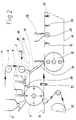
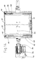
- the system or device shown schematically in FIG. 1 for multiple coating of web-like carrier material or for the production of carrierless webs consists of the machine frame 1 with the heated or unheated and driven transfer rollers 2 and 3 arranged above it for two material webs 4 and 5, which are made by one supply roll, not shown, are removed or have also passed through an impregnation bath, also not shown. Furthermore, web edge controls 6, 7 and 8 are provided which monitor and if necessary correct the web path by means of photo-optical, mechanical or pneumatic edge scanning and a corresponding control device, so that an exact web path is ensured.
- a coating device 9 is arranged for coating the underside of the web, several of which can optionally be provided one behind the other in order to to be able to carry out a multiple coating of the carrier material.
- This coating device 9 with support table 81 will be discussed in more detail in connection with FIGS. 4, 5 and 6.
- the device 9 is assigned a heated collecting trough 10 for excess material overflowing at the edges.
- the coating material is in fact added in excess, so that it flows down at the edges and edges of the carrier 4 or 5 and thus the carrier edges are also completely covered and coated.
- Lateral wipers 79 which are curved, wipe off excess material and smooth the edge.
- a knife 80 is provided, which is arranged on the underside of the carrier and has a smoothing effect here.
- the system has a heated deflecting roller 11, to which a stripping device can also be assigned.
- a container or bunker 12 for under-spreading is arranged, which is coupled to a dust extraction system 13. Excess under-sprinkling is collected in the tub 14 and conveyed back to the bunker 12.
- a probe 92 can also be seen in FIG. 2, with which the position of the side edges of the carrier is recognized and measured.
- the system has a cooling belt 17 resting on the two rollers 15 and 16, which is designed as an endlessly welded steel belt in a cantilever construction, that is to say self-supporting.
- the cooling belt 17 is held by cantilever arms 18, so that a quick change of the cooling belt 17 can be accomplished.
- the cooling takes place via the cooling device 73, which is designed as a water nozzle, cooling trough, etc. can (see for example also Fig. 2 and 3).
- Two further coating devices 22, 23 are provided just above the cooling belt 17, which serve to coat the top of the carrier, the device 23 essentially corresponding in structure to the coating station 9, which is described in connection with FIGS. 4, 5 and 6, during the Structure of the device 22 is shown in FIGS. 10 and 11.
- a support roller 24 is provided under each of the coating stations 22, 23 and is arranged within the cooling belt 17.
- the excess material stripped from the carrier and collected in the collecting trough 10 is fed directly to the device 22.
- the container 25 for the main and top sprinkling with suction 26 for accumulating dust is arranged, which is followed by the container 27 for the edge sprinkling, with the feed 28 or, in the case of edge spreading on both sides, is equipped with two such feeds 28.
- the suction 29 for excess edge sprinkling is arranged downstream of the feed 28, which prevents the sprinkling from mixing.
- Two rubberized press-in rollers 30 ensure that the sprinkling material is pressed into the applied top layer, while the return conveyor 31 feeds excess material from the top sprinkling back into the container 25, so that no material is lost.
- a cyclone device can also be arranged downstream of the suction and return conveyor systems, which separates the sprinkling material and the dust from one another.
- the dust can then be disposed of and fed to the mixing plant for the bitumen mass as a filler.
- the system is equipped with a further cooling belt system 32, which connects to the cooling belt 17.
- this second cooling belt 32 which is also a steel belt with nozzle cooling
- roller cooling can alternatively also be provided, which is shown in dash-dot lines in FIG. 1 and bears the reference number 33.
- a coating device 35 is arranged above the roller 34 carrying the cooling belt 32, which in turn is designed essentially like the coating stations already mentioned. Beneath the roller 34 is a spray head 36 corresponding to the spray head 21, with which the release agent is sprayed onto the surface of the cooling belt 32.
- a deflection roller 37 is arranged between the two cooling belts 17 and 32 and is immersed in a water bath 38 with height adjustment of the cooling water pan for moistening and cooling on bare product surfaces.
- the water bath 38 is lowered so that the deflecting roller 37 runs outside the water bath 38.
- a rubberized press-in roller 39 for the top layer lying in front of the coating station 35 presses against the roller 34 of the cooling belt 32.
- the brush roller 40 provided in the region of the deflecting roller 37 in a spiral configuration ensures the removal of the remaining excess sprinkling to the side.
- a coating device 42 is arranged above the support roller 41, which can also be referred to as a bitumen film production head.
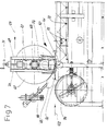
- the structure of this device, with which carrier-free webs can be produced and which is also used for coating films or roofing webs, can be seen above all from FIG. 7, which will be discussed in more detail below.
- Additional carrier materials or cover sheets can be drawn off from a rolling device 43.
- Both the cooling belt 17 and the cooling belt 32 are equipped with cooling devices, namely in particular spray devices for cooling liquid, which can be seen in more detail in FIGS. 2 and 7.
- 32 nozzles 44 are provided outside the cooling belt for additional water rinsing.
- Slidable water vapor extraction hoods 45 with fans 46 for extracting the water vapor are also arranged on the cooling belt 32.
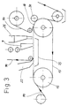
- FIG. 3 A simplified basic version of the system is shown in Fig. 3. Since the system is built in a modular system, it can be expanded and retrofitted at any time according to requirements.
- two coating devices 9 and 22 are arranged one behind the other, which is followed by the sprinkling device 25.
- Foil 90 is supplied as required and desired product so that, for example, products can be produced which are bare at the top and / or bottom, which have a foil at the top and / or bottom, which are provided with sprinkling on the top, etc.
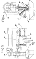
- the basic design of the coating devices 9, 23 or 35 can be seen from FIGS. 4, 5 and 6.
- the coating device or station is equipped with an application box 53 for the mass to be applied, which can be heated by heating rods 55 inserted into the rear wall 54. Heating mats or thermal oil can also be used for heating.
- the width of the outflow gap 56 can be adjusted according to the requirements and depending on the masses processed by moving the rear wall 54 which can be fixed with screws or nuts 124.
- the length of the outflow gap 56 can also be adjusted as a function of or in coordination with the width of the carrier web to be coated.
- the side walls 58 of the order box 53 are each laterally displaceable for themselves.
- transverse walls 59 of both side walls 58 connected to the side walls 58 overlap and can be moved one above the other, screws with self-locking nuts 60 engaging in elongated holes 82 in the transverse walls 59.
- the transverse displacement of each of the side walls 58 takes place in each case by means of a threaded spindle 61 by hand or by motor.
- the entire coating device which is supported on transverse rails 83 on the machine frame, can be displaced and adjusted transversely to the production direction, that is to say the direction of travel of the carrier, depending on the controlled position of the carrier via the spindle 84 and bevel gear 85.
- the coating device is also equipped with a doctor blade 62 which, depending on the requirement, is exchangeably fastened to the application box 53 against another doctor blade and can likewise be heated by inserted heating rods 63 or the like.
- the order box 53 also has a sliding wedge 64 with an adjusting screw 57 which consists of plastic or has a sliding layer made of plastic, which allows easy sliding when touching the cooling belt and at the same time ensures the lateral seal or the same edge.
- the mass to be coated is introduced into the application box 53 via the feed 78.
- the entire box 53 is adjustable in the vertical direction, so that the thickness of the layer to be applied to the carrier can be adjusted exactly.
- This coating device 42 is shown in more detail.
- This coating device 42 is used for coating films, but also for the strapless production of sheet material, be it bitumen or sulfur. However, it can also be used, for example, to produce chocolate masses in web form.
- the coating device 42 has a heated box 65 for the mass to be applied, which is fed to the box 65 via the feed device 66. In the case of bitumen, this is introduced at a temperature of approximately 150 to 210 ° C.
- the box 65 also has side walls which can be moved in the transverse direction, so that the outflow width can be set exactly.
- the coating device 42 is equipped with a cooling roller 67, the surface or outside temperature of which is cooled to approximately 5 ° C.
- the Entire cooling roller 67 can be adjusted in the height direction via the adjusting device 69, which essentially consists of the spindle drive 70, the handwheel 71 (or a servomotor) and the guide 72.
- the cooling roller 67 essentially consists of an inner jacket 86, which absorbs the forces acting on the roller, and an outer jacket 87, which is kept much thinner, so that a good cooling effect is achieved.
- the cooling water flowing in several sections formed between the jacket 86 and 87 from the inlets 88 to the outlets 89 ensures a homogeneous temperature distribution over the length of the roller 67.
- the device 42 is arranged above the cooling belt 32 and has the support roller 41 already mentioned, absorbs the pending and occurring forces and also supports the cooling belt 32.
- the cooling roller 67 is driven by means of the direct current motor 74.
- the coating device 22 is shown, which is supported on transverse rails 94 and can be displaced by the motor 95 via the spindle drive 96 in the transverse direction according to the respective position of the carrier, signaled by the probe 92.
- the heating roller 98 upstream of the heatable doctor blade 97 is adjustable in height.
- the rear wall 99 of the application box is adjustable to change the exit gap width. The mass is supplied via the inlet 100, excess mass being fed from the collecting trough 10 when processing the same masses.
- a number of heatable rollers are used in the system. These rollers can be heated electrically, for example.
- An electrically heated heating roller is shown in an enlarged view in Fig. 14.
- a temperature sensor 105 ensures that the desired temperature is maintained.
- the two end disks 106 and 107 are fastened to the fastening disks 108 and 109 by means of screws 110, the fastening disks 108, 109 and the heating mat 101 being held in place by means of the anti-rotation device 111. Seated seals 112 between the end disks 106, 107 and the outer jacket 113 seal the heating roller.
- the sprinkling device 25 for the main sprinkling with which coarse, platelet-shaped and fine sprinkling material is applied, is also shown schematically in FIG.
- the outflow width of the funnel and thus the spreading amount applied per unit of time can be regulated.
- two inclinable sieves 117 and 118 are arranged, of which the sieve 117 separates the coarse material that slides down over guide plates 119 and is aligned in such a way that the platelet-shaped components of the previously applied coating at a flat angle or are fed approximately tangentially so that they come to lie flat on it.
- the fine material again separated in terms of size by the sieve 118, passes through the guide channel 120 in the course of production after the rough sprinkling onto the coating and fills the remaining sprinkling gaps, so that a very good and dense sprinkling of the layer mass is ensured.
- the mode of operation of the system for the top and bottom coating of a web-shaped carrier will now be briefly discussed, as can be seen in FIGS. 1 and 2.
- the web-shaped carrier material 5 reaches the coating device 9 for the underside via the various deflecting rollers 3 and edge controls 6 and 7.
- the coating composition for example bitumen, is applied to the carrier 5 in the desired thickness, then the scattering material for the under-spreading is applied via the spreading device 12. Dust is sucked off via the suction 13. Multiple coating can be carried out by arranging further coating devices.
- the carrier 5 provided with the undercoat is then fed to the coating device 22 for the topcoat.
- edge sprinkling is then applied via the feeds 28 or foil 52, excess material is sucked off via the device 29, and the top sprinkling from the bunker 25 is given up.
- the cooling belt 17, on which the carrier 5 rests when the top coating is applied, is cooled via cooling nozzles 73.
- the film can also be fed directly from the deflection roller 6 to the coating device 22, as also indicated in FIG. 10.
- Roll-off devices 75, 76 for foils or additional supports or edge foils are also available. It should also be pointed out that an excess is added, particularly in the case of cold self-adhesive materials which are pulled off the roll 47, so that shrinkage stresses which can occur later are compensated for.
- the mass (bitumen) reaches - cf. also Fig. 8 - directly from the feed box 65 of the device 42 to the cooling belt 32.
- the bitumen initially sticks to the cooling belt 32, since this is not or only slightly cooled in this area, and is removed from the cooling belt 32 taken away.
- films 121, 122 can be fed in at the bottom and / or at the top will.
- the rear wall 123 of the application box 65 runs approximately equidistant from the jacket of the roller 67, so that heating of the cooling roller 67 is prevented in this area.
Landscapes
- Engineering & Computer Science (AREA)
- Mechanical Engineering (AREA)
- Application Of Or Painting With Fluid Materials (AREA)
- Coating Apparatus (AREA)
- Slide Fasteners, Snap Fasteners, And Hook Fasteners (AREA)
Priority Applications (1)
| Application Number | Priority Date | Filing Date | Title |
|---|---|---|---|
| AT90119939T ATE103845T1 (de) | 1989-10-20 | 1990-10-17 | Anlage zur beschichtung bahnfoermiger traegermaterialien oder zur herstellung traegerloser bahnen. |
Applications Claiming Priority (2)
| Application Number | Priority Date | Filing Date | Title |
|---|---|---|---|
| DE3935059A DE3935059C1 (sk) | 1989-10-20 | 1989-10-20 | |
| DE3935059 | 1989-10-20 |
Publications (3)
| Publication Number | Publication Date |
|---|---|
| EP0423774A2 EP0423774A2 (de) | 1991-04-24 |
| EP0423774A3 EP0423774A3 (en) | 1991-11-13 |
| EP0423774B1 true EP0423774B1 (de) | 1994-04-06 |
Family
ID=6391899
Family Applications (1)
| Application Number | Title | Priority Date | Filing Date |
|---|---|---|---|
| EP90119939A Expired - Lifetime EP0423774B1 (de) | 1989-10-20 | 1990-10-17 | Anlage zur Beschichtung bahnförmiger Trägermaterialien oder zur Herstellung trägerloser Bahnen |
Country Status (8)
| Country | Link |
|---|---|
| US (1) | US5145529A (sk) |
| EP (1) | EP0423774B1 (sk) |
| JP (1) | JPH03135467A (sk) |
| CN (1) | CN1023384C (sk) |
| AT (1) | ATE103845T1 (sk) |
| CA (1) | CA2028035A1 (sk) |
| DE (2) | DE3935059C1 (sk) |
| RU (1) | RU2074918C1 (sk) |
Cited By (1)
| Publication number | Priority date | Publication date | Assignee | Title |
|---|---|---|---|---|
| DE102006035856A1 (de) * | 2006-08-01 | 2008-02-14 | Rümmer System Engineering GmbH | Beschichtungsvorrichtung zur planmäßigen Aufgabe von Deckmassen auf die Oberseite eines Trägermaterials |
Families Citing this family (26)
| Publication number | Priority date | Publication date | Assignee | Title |
|---|---|---|---|---|
| EP0603776A1 (en) * | 1992-12-22 | 1994-06-29 | Minnesota Mining And Manufacturing Company | Free span coater with backside support |
| DE19733333A1 (de) * | 1997-08-01 | 1999-02-04 | Voith Sulzer Papiermasch Gmbh | Vorrichtung zum direkten oder indirekten Auftragen eines flüssigen oder pastösen Auftragsmediums auf eine laufende Materialbahn, insbesondere aus Papier oder Karton |
| DE19800955A1 (de) | 1998-01-13 | 1999-07-15 | Voith Sulzer Papiertech Patent | Vorrichtung zum Auftragen eines flüssigen oder pastösen Auftragsmediums auf eine laufende Materialbahn, insbesondere aus Papier oder Karton |
| DE19800954A1 (de) * | 1998-01-13 | 1999-07-15 | Voith Sulzer Papiertech Patent | Vorrichtung zum direkten oder indirekten Auftragen eines flüssigen oder pastösen Auftragsmediums auf eine laufende Materialbahn, insbesondere aus Papier oder Karton |
| JP2010017625A (ja) * | 2008-07-09 | 2010-01-28 | Mitsubishi Electric Corp | 放熱媒体塗布装置 |
| JP5261798B2 (ja) * | 2009-02-19 | 2013-08-14 | 三菱電機株式会社 | 放熱媒体塗布装置 |
| KR101028038B1 (ko) * | 2010-10-04 | 2011-04-08 | 주식회사 코엠에스 | 반도체 제조용 필름 코팅장치 |
| FR2974745B1 (fr) * | 2011-05-06 | 2013-04-26 | Commissariat Energie Atomique | Dispositif et procede de depot par enduction a la racle d'encre a base de cuivre et d'indium |
| JP2013000630A (ja) * | 2011-06-14 | 2013-01-07 | J-Chemical:Kk | 被塗布板表面への塗布剤の塗布方法および装置 |
| CN103230857B (zh) * | 2013-04-28 | 2015-05-20 | 哈尔滨工业大学 | 自动化层层浸镀法制备聚电解质多层膜的装置的控制方法 |
| CN103611653B (zh) * | 2013-12-13 | 2015-09-16 | 厦门惟华光能有限公司 | 有机太阳能电池实验用涂布机 |
| JP6054919B2 (ja) * | 2014-07-02 | 2016-12-27 | トヨタ自動車株式会社 | リチウムイオン二次電池用電極の製造方法 |
| CN104985731A (zh) * | 2015-07-02 | 2015-10-21 | 重庆永钢橡塑有限责任公司 | 超长链条自动浸塑设备 |
| CN105344545B (zh) * | 2015-10-30 | 2019-11-15 | 芜湖凯尔电气科技有限公司 | 手机锂电池极板刷粉装置 |
| CN105478477B (zh) * | 2016-01-01 | 2018-03-23 | 杭州巨力绝缘材料有限公司 | 铝箔气隙修补生产线及填充方法 |
| CN105665232B (zh) * | 2016-04-14 | 2018-01-26 | 江苏中邦输送带有限公司 | 一种特氟龙粘胶带上胶厚度可调浸制机 |
| CN109127274B (zh) * | 2018-09-30 | 2021-08-31 | 芜湖华烨工业用布有限公司 | 一种工业用布的浸胶装置 |
| CN110801992B (zh) * | 2019-11-18 | 2021-03-23 | 武冈市申靓建筑材料有限公司 | 一种塑料板材覆膜涂料装置 |
| CN111842051B (zh) * | 2020-06-20 | 2021-08-13 | 科顺防水科技股份有限公司 | 一种沥青防水卷材涂布用溢料机构 |
| KR102297774B1 (ko) * | 2021-02-09 | 2021-09-03 | (주)테라시스 | 분말 스프레이 방식을 이용한 기능성 시트 및 이의 제조 방법 |
| CN113275199A (zh) * | 2021-06-01 | 2021-08-20 | 深圳市曼恩斯特科技股份有限公司 | 一种涂布机构及涂布方法 |
| CN113799305B (zh) * | 2021-09-16 | 2023-04-21 | 铁科纵横(天津)科技发展有限公司 | 自动撒花装置 |
| CN114918105B (zh) * | 2022-05-26 | 2023-04-28 | 广东嘉拓自动化技术有限公司 | 消除烘箱内基材抖动对涂布不良影响的双面底涂涂布设备 |
| CN115041363B (zh) * | 2022-06-29 | 2023-07-28 | 西安易朴通讯技术有限公司 | 硅脂涂覆装置 |
| CN115041355B (zh) * | 2022-07-11 | 2024-01-12 | 廊坊瑞格新材料科技有限公司 | 一种弹力布涂层用的凝固浸渍料槽装置 |
| CN116238138B (zh) * | 2023-03-31 | 2024-05-07 | 镇江越升智能装备制造有限公司 | 一种锂电池用湿法隔膜线体小纵拉设备及其使用方法 |
Family Cites Families (19)
| Publication number | Priority date | Publication date | Assignee | Title |
|---|---|---|---|---|
| US2054115A (en) * | 1935-09-16 | 1936-09-15 | Marathon Paper Mills Co | Composition for coating, laminating, and film forming |
| US2249088A (en) * | 1940-01-09 | 1941-07-15 | Liquafilm Corp | Coating apparatus and method |
| GB600685A (en) * | 1945-06-12 | 1948-04-15 | Noel Baville | A method and a plant for continuously cooling and solidifying by temperature lowering substances that are liquid hot and particularly pitch, bitumen, asphalt, resins and the like |
| US2678284A (en) * | 1949-06-24 | 1954-05-11 | Brown Bridge Mills | Method of producing a thermoplastic adhesive and product thereof |
| US2649758A (en) * | 1950-12-05 | 1953-08-25 | Us Rubber Co | Coating machine with circulating system |
| US2839025A (en) * | 1953-07-17 | 1958-06-17 | Royal Mcbee Corp | Wax carbon printing press |
| US2905569A (en) * | 1955-01-03 | 1959-09-22 | Bird & Son | Method of applying particles to a surface in predetermined patterns and apparatus therefor |
| US2992627A (en) * | 1958-10-13 | 1961-07-18 | Chapman Chem Co | Applicator |
| US3079889A (en) * | 1959-06-03 | 1963-03-05 | Black Clawson Co | Paper machinery |
| US3797453A (en) * | 1970-08-21 | 1974-03-19 | Afco Prod Inc | Apparatus coating sheeted material with a tacky substance |
| CH543903A (de) * | 1971-11-18 | 1973-11-15 | Kleinewefers Ind Co Gmbh | Einrichtung zum Imprägnieren und Färben kontinuierlich zu behandelnder breiter Textilbahnen |
| DE2722595A1 (de) * | 1977-05-18 | 1978-11-23 | Friz Gmbh & Co Helmut | Klebstoffauftragstation fuer eine kaschiervorrichtung |
| DE2837913C2 (de) * | 1978-08-31 | 1982-10-21 | ER-WE-PA Maschinenfabrik und Eisengießerei GmbH, 4006 Erkrath | Walze mit steuerbarer Durchbiegung, insbesondere für Maschinen zur Erzeugung und Verarbeitung von Bahnen aus Papier oder Kunststoff |
| US4277518A (en) * | 1979-11-13 | 1981-07-07 | Gyrex Corp. | Solder-coating method |
| JPS591654B2 (ja) * | 1980-10-02 | 1984-01-13 | レンゴ−株式会社 | コルゲ−タにおけるウエブ材の位置ずれ調整方法及び装置 |
| US4474845A (en) * | 1982-08-26 | 1984-10-02 | General Motors Corporation | Compacted sheet molding compound |
| DE3343313A1 (de) * | 1983-11-30 | 1985-06-05 | J.M. Voith Gmbh, 7920 Heidenheim | Walze zur behandlung von bahnen, vorzugsweise papierbahnen |
| GB2159066B (en) * | 1984-05-25 | 1987-10-07 | Aryan Group Limited | A method of, and apparatus for, continuously forming sheeting and the manufacture of building panels from such sheeting |
| US4626452A (en) * | 1985-03-20 | 1986-12-02 | Poterala Robert J | Adjustable sealing dams for a coating machine and method |
-
1989
- 1989-10-20 DE DE3935059A patent/DE3935059C1/de not_active Expired - Lifetime
-
1990
- 1990-10-17 DE DE90119939T patent/DE59005257D1/de not_active Expired - Fee Related
- 1990-10-17 AT AT90119939T patent/ATE103845T1/de not_active IP Right Cessation
- 1990-10-17 EP EP90119939A patent/EP0423774B1/de not_active Expired - Lifetime
- 1990-10-18 JP JP2277934A patent/JPH03135467A/ja active Pending
- 1990-10-19 RU SU904831220A patent/RU2074918C1/ru active
- 1990-10-19 CA CA002028035A patent/CA2028035A1/en not_active Abandoned
- 1990-10-19 US US07/600,408 patent/US5145529A/en not_active Expired - Fee Related
- 1990-10-20 CN CN90108505A patent/CN1023384C/zh not_active Expired - Fee Related
Cited By (2)
| Publication number | Priority date | Publication date | Assignee | Title |
|---|---|---|---|---|
| DE102006035856A1 (de) * | 2006-08-01 | 2008-02-14 | Rümmer System Engineering GmbH | Beschichtungsvorrichtung zur planmäßigen Aufgabe von Deckmassen auf die Oberseite eines Trägermaterials |
| DE102006035856B4 (de) * | 2006-08-01 | 2008-10-16 | Rümmer System Engineering GmbH | Beschichtungsvorrichtung zur planmäßigen Aufgabe von Deckmassen auf die Oberseite eines Trägermaterials |
Also Published As
| Publication number | Publication date |
|---|---|
| DE3935059C1 (sk) | 1991-02-21 |
| CN1023384C (zh) | 1994-01-05 |
| CA2028035A1 (en) | 1991-04-21 |
| ATE103845T1 (de) | 1994-04-15 |
| DE59005257D1 (de) | 1994-05-11 |
| EP0423774A3 (en) | 1991-11-13 |
| CN1051315A (zh) | 1991-05-15 |
| US5145529A (en) | 1992-09-08 |
| RU2074918C1 (ru) | 1997-03-10 |
| JPH03135467A (ja) | 1991-06-10 |
| EP0423774A2 (de) | 1991-04-24 |
Similar Documents
| Publication | Publication Date | Title |
|---|---|---|
| EP0423774B1 (de) | Anlage zur Beschichtung bahnförmiger Trägermaterialien oder zur Herstellung trägerloser Bahnen | |
| EP2512691B1 (de) | Verfahren und vorrichtung zum elektrostatischen abscheiden von overspray mit einem absorptionsmittel | |
| WO2013174659A1 (de) | Vorrichtung und verfahren zum auftragen von farbe und/oder eines klebebands auf einen plattenförmigen gegenstand | |
| DE2452784B2 (de) | Verfahren und Vorrichtung zur kontinuierlichen Beschichtung eines Materialstreifens, z.B. einer Papierbahn | |
| EP3526042B1 (de) | Vorrichtung zum kaschieren eines substrates mit einem thermoplastischen beschichtungsmaterial | |
| DE102011120498B4 (de) | Werkzeug zum Erzeugen einer Schicht mit mikrostrukturierter Außenfläche auf einer Substratoberfläche | |
| EP2512690A1 (de) | Verfahren und vorrichtung zum elektrostatischen abscheiden von overspray | |
| DE2504701C2 (de) | Verfahren und Vorrichtung zum beidseitigen Beschichten einer von unten nach oben bewegten Bahn | |
| CH680709A5 (sk) | ||
| EP1831465B1 (de) | Vorrichtung zum auftragen einer beschichtungsmasse auf eine papierbahn | |
| EP2841258A1 (de) | Verfahren und rakelvorrichtung zum aufrakeln einer harzpaste auf eine trägerfolie und eine harzmattenanlage zur herstellung von harzmatten | |
| EP0677613B1 (de) | Vorrichtung zum Auftragen von mindestens einem flüssigen Medium auf eine laufende Materialbahn | |
| EP2277630A2 (de) | Vorrichtung zum Beschichten einer durchlaufenden Bahn | |
| EP1896190B1 (de) | Nip-beschichtung | |
| DE4334405C2 (de) | Transportvorrichtung | |
| EP1733802A1 (de) | Vorrichtung zum Auftragen von flüssigen bis pastösen Suspensionen auf Papier- oder Kartonbahnen | |
| EP1793036B1 (de) | Verfahren zur Herstellung flüssigkeitsundurchlässiger Papiermaschinenbänder sowie Beschichtungsvorrichtung hierfür | |
| DE2136461B2 (de) | Vorrichtung zur ganzflächig dünnen und dichten Beschichtung von flächigem Textilgut mit in der Wärme erweichendem Beschichtungsmaterial | |
| DE202008000451U1 (de) | Beschichtungsdüse, Beschichtungsanordnung mit der Beschichtungsdüse | |
| DE19603861C1 (de) | Vorrichtung zum Beschichten einer Materialbahn, insbesondere einer Papier- oder Kartonbahn | |
| DE3120716A1 (de) | "verfahren und vorrichtung zum unter-druck-zufuehren eines beschichtungsmaterials auf eine bewegte bahn" | |
| DE1704780C3 (de) | Vorrichtung zum Herstellen von Folien aus einem thermoplastischen Hochpolymeren | |
| WO2009024297A1 (de) | Verfahren und vorrichtung zum flächigen auftragen eines fliessfähigen mediums auf eine materialbahn | |
| AT247702B (de) | Beschichtungsvorrichtung, insbesondere zum Auftragen von Schichten aus verschiedenen plastischen Materialien auf ein Unterlageband | |
| DE102010029815A1 (de) | Verfahren und Vorrichtung zum ein- oder beidseitigen Auftragen eines flüssigen oder pastösen Auftragsmediums in Form wenigstens eines Sprühstrahles |
Legal Events
| Date | Code | Title | Description |
|---|---|---|---|
| PUAI | Public reference made under article 153(3) epc to a published international application that has entered the european phase |
Free format text: ORIGINAL CODE: 0009012 |
|
| AK | Designated contracting states |
Kind code of ref document: A2 Designated state(s): AT BE CH DE DK ES FR GB GR IT LI LU NL SE |
|
| PUAL | Search report despatched |
Free format text: ORIGINAL CODE: 0009013 |
|
| AK | Designated contracting states |
Kind code of ref document: A3 Designated state(s): AT BE CH DE DK ES FR GB GR IT LI LU NL SE |
|
| 17P | Request for examination filed |
Effective date: 19920407 |
|
| 17Q | First examination report despatched |
Effective date: 19930715 |
|
| GRAA | (expected) grant |
Free format text: ORIGINAL CODE: 0009210 |
|
| AK | Designated contracting states |
Kind code of ref document: B1 Designated state(s): AT BE CH DE DK ES FR GB GR IT LI LU NL SE |
|
| PG25 | Lapsed in a contracting state [announced via postgrant information from national office to epo] |
Ref country code: IT Free format text: LAPSE BECAUSE OF FAILURE TO SUBMIT A TRANSLATION OF THE DESCRIPTION OR TO PAY THE FEE WITHIN THE PRE;WARNING: LAPSES OF ITALIAN PATENTS WITH EFFECTIVE DATE BEFORE 2007 MAY HAVE OCCURRED AT ANY TIME BEFORE 2007. THE CORRECT EFFECTIVE DATE MAY BE DIFFERENT FROM THE ONE RECORDED.SCRIBED TIME-LIMIT Effective date: 19940406 Ref country code: DK Effective date: 19940406 Ref country code: GR Free format text: LAPSE BECAUSE OF FAILURE TO SUBMIT A TRANSLATION OF THE DESCRIPTION OR TO PAY THE FEE WITHIN THE PRESCRIBED TIME-LIMIT Effective date: 19940406 Ref country code: GB Effective date: 19940406 Ref country code: ES Free format text: THE PATENT HAS BEEN ANNULLED BY A DECISION OF A NATIONAL AUTHORITY Effective date: 19940406 Ref country code: FR Effective date: 19940406 Ref country code: BE Effective date: 19940406 Ref country code: NL Effective date: 19940406 Ref country code: SE Free format text: THE PATENT HAS BEEN ANNULLED BY A DECISION OF A NATIONAL AUTHORITY Effective date: 19940406 |
|
| REF | Corresponds to: |
Ref document number: 103845 Country of ref document: AT Date of ref document: 19940415 Kind code of ref document: T |
|
| REF | Corresponds to: |
Ref document number: 59005257 Country of ref document: DE Date of ref document: 19940511 |
|
| EN | Fr: translation not filed | ||
| NLV1 | Nl: lapsed or annulled due to failure to fulfill the requirements of art. 29p and 29m of the patents act | ||
| GBV | Gb: ep patent (uk) treated as always having been void in accordance with gb section 77(7)/1977 [no translation filed] |
Effective date: 19940406 |
|
| PG25 | Lapsed in a contracting state [announced via postgrant information from national office to epo] |
Ref country code: LU Free format text: LAPSE BECAUSE OF NON-PAYMENT OF DUE FEES Effective date: 19941031 |
|
| PLBE | No opposition filed within time limit |
Free format text: ORIGINAL CODE: 0009261 |
|
| STAA | Information on the status of an ep patent application or granted ep patent |
Free format text: STATUS: NO OPPOSITION FILED WITHIN TIME LIMIT |
|
| 26N | No opposition filed | ||
| PGFP | Annual fee paid to national office [announced via postgrant information from national office to epo] |
Ref country code: AT Payment date: 19951020 Year of fee payment: 6 |
|
| PGFP | Annual fee paid to national office [announced via postgrant information from national office to epo] |
Ref country code: CH Payment date: 19951023 Year of fee payment: 6 |
|
| PG25 | Lapsed in a contracting state [announced via postgrant information from national office to epo] |
Ref country code: AT Effective date: 19961017 |
|
| PG25 | Lapsed in a contracting state [announced via postgrant information from national office to epo] |
Ref country code: LI Effective date: 19961031 Ref country code: CH Effective date: 19961031 |
|
| REG | Reference to a national code |
Ref country code: CH Ref legal event code: PL |
|
| PGFP | Annual fee paid to national office [announced via postgrant information from national office to epo] |
Ref country code: DE Payment date: 20071029 Year of fee payment: 18 |
|
| PG25 | Lapsed in a contracting state [announced via postgrant information from national office to epo] |
Ref country code: DE Free format text: LAPSE BECAUSE OF NON-PAYMENT OF DUE FEES Effective date: 20090501 |