EP0409561B1 - Méthodes de fabrication d'éléments semi-conducteurs du type MIS - Google Patents
Méthodes de fabrication d'éléments semi-conducteurs du type MIS Download PDFInfo
- Publication number
- EP0409561B1 EP0409561B1 EP90307802A EP90307802A EP0409561B1 EP 0409561 B1 EP0409561 B1 EP 0409561B1 EP 90307802 A EP90307802 A EP 90307802A EP 90307802 A EP90307802 A EP 90307802A EP 0409561 B1 EP0409561 B1 EP 0409561B1
- Authority
- EP
- European Patent Office
- Prior art keywords
- film
- sio
- substrate
- gate electrode
- side walls
- Prior art date
- Legal status (The legal status is an assumption and is not a legal conclusion. Google has not performed a legal analysis and makes no representation as to the accuracy of the status listed.)
- Expired - Lifetime
Links
- 239000004065 semiconductor Substances 0.000 title claims description 19
- 238000000034 method Methods 0.000 title claims description 15
- 238000004519 manufacturing process Methods 0.000 title claims description 8
- VYPSYNLAJGMNEJ-UHFFFAOYSA-N Silicium dioxide Chemical compound O=[Si]=O VYPSYNLAJGMNEJ-UHFFFAOYSA-N 0.000 claims description 144
- 229910052681 coesite Inorganic materials 0.000 claims description 72
- 229910052906 cristobalite Inorganic materials 0.000 claims description 72
- 239000000377 silicon dioxide Substances 0.000 claims description 72
- 229910052682 stishovite Inorganic materials 0.000 claims description 72
- 229910052905 tridymite Inorganic materials 0.000 claims description 72
- 239000000758 substrate Substances 0.000 claims description 42
- 239000012535 impurity Substances 0.000 claims description 11
- BOTDANWDWHJENH-UHFFFAOYSA-N Tetraethyl orthosilicate Chemical compound CCO[Si](OCC)(OCC)OCC BOTDANWDWHJENH-UHFFFAOYSA-N 0.000 claims description 7
- BLRPTPMANUNPDV-UHFFFAOYSA-N Silane Chemical compound [SiH4] BLRPTPMANUNPDV-UHFFFAOYSA-N 0.000 claims description 4
- 238000001039 wet etching Methods 0.000 claims description 3
- XUIMIQQOPSSXEZ-UHFFFAOYSA-N Silicon Chemical compound [Si] XUIMIQQOPSSXEZ-UHFFFAOYSA-N 0.000 claims description 2
- 230000001590 oxidative effect Effects 0.000 claims description 2
- 229910052710 silicon Inorganic materials 0.000 claims description 2
- 239000010703 silicon Substances 0.000 claims description 2
- 238000001020 plasma etching Methods 0.000 claims 3
- 239000011247 coating layer Substances 0.000 claims 2
- -1 phosphorus ions Chemical class 0.000 description 10
- 229910052785 arsenic Inorganic materials 0.000 description 9
- 230000002093 peripheral effect Effects 0.000 description 7
- 239000013078 crystal Substances 0.000 description 5
- 230000007547 defect Effects 0.000 description 5
- 230000003647 oxidation Effects 0.000 description 5
- 238000007254 oxidation reaction Methods 0.000 description 5
- 229910021420 polycrystalline silicon Inorganic materials 0.000 description 4
- 230000015572 biosynthetic process Effects 0.000 description 3
- 230000015556 catabolic process Effects 0.000 description 3
- 238000005530 etching Methods 0.000 description 3
- 238000000137 annealing Methods 0.000 description 2
- 230000003247 decreasing effect Effects 0.000 description 2
- 238000002513 implantation Methods 0.000 description 2
- 238000005468 ion implantation Methods 0.000 description 2
- 229910052698 phosphorus Inorganic materials 0.000 description 2
- 239000011574 phosphorus Substances 0.000 description 2
- RQNWIZPPADIBDY-UHFFFAOYSA-N arsenic atom Chemical compound [As] RQNWIZPPADIBDY-UHFFFAOYSA-N 0.000 description 1
- 238000006731 degradation reaction Methods 0.000 description 1
- 230000008021 deposition Effects 0.000 description 1
- 238000009792 diffusion process Methods 0.000 description 1
Images

Classifications
-
- H—ELECTRICITY
- H01—ELECTRIC ELEMENTS
- H01L—SEMICONDUCTOR DEVICES NOT COVERED BY CLASS H10
- H01L21/00—Processes or apparatus adapted for the manufacture or treatment of semiconductor or solid state devices or of parts thereof
- H01L21/02—Manufacture or treatment of semiconductor devices or of parts thereof
- H01L21/04—Manufacture or treatment of semiconductor devices or of parts thereof the devices having at least one potential-jump barrier or surface barrier, e.g. PN junction, depletion layer or carrier concentration layer
- H01L21/18—Manufacture or treatment of semiconductor devices or of parts thereof the devices having at least one potential-jump barrier or surface barrier, e.g. PN junction, depletion layer or carrier concentration layer the devices having semiconductor bodies comprising elements of Group IV of the Periodic System or AIIIBV compounds with or without impurities, e.g. doping materials
- H01L21/22—Diffusion of impurity materials, e.g. doping materials, electrode materials, into or out of a semiconductor body, or between semiconductor regions; Interactions between two or more impurities; Redistribution of impurities
- H01L21/225—Diffusion of impurity materials, e.g. doping materials, electrode materials, into or out of a semiconductor body, or between semiconductor regions; Interactions between two or more impurities; Redistribution of impurities using diffusion into or out of a solid from or into a solid phase, e.g. a doped oxide layer
- H01L21/2251—Diffusion into or out of group IV semiconductors
- H01L21/2252—Diffusion into or out of group IV semiconductors using predeposition of impurities into the semiconductor surface, e.g. from a gaseous phase
- H01L21/2253—Diffusion into or out of group IV semiconductors using predeposition of impurities into the semiconductor surface, e.g. from a gaseous phase by ion implantation
-
- H—ELECTRICITY
- H01—ELECTRIC ELEMENTS
- H01L—SEMICONDUCTOR DEVICES NOT COVERED BY CLASS H10
- H01L29/00—Semiconductor devices adapted for rectifying, amplifying, oscillating or switching, or capacitors or resistors with at least one potential-jump barrier or surface barrier, e.g. PN junction depletion layer or carrier concentration layer; Details of semiconductor bodies or of electrodes thereof ; Multistep manufacturing processes therefor
- H01L29/66—Types of semiconductor device ; Multistep manufacturing processes therefor
- H01L29/66007—Multistep manufacturing processes
- H01L29/66075—Multistep manufacturing processes of devices having semiconductor bodies comprising group 14 or group 13/15 materials
- H01L29/66227—Multistep manufacturing processes of devices having semiconductor bodies comprising group 14 or group 13/15 materials the devices being controllable only by the electric current supplied or the electric potential applied, to an electrode which does not carry the current to be rectified, amplified or switched, e.g. three-terminal devices
- H01L29/66409—Unipolar field-effect transistors
- H01L29/66477—Unipolar field-effect transistors with an insulated gate, i.e. MISFET
- H01L29/66568—Lateral single gate silicon transistors
- H01L29/66575—Lateral single gate silicon transistors where the source and drain or source and drain extensions are self-aligned to the sides of the gate
- H01L29/6659—Lateral single gate silicon transistors where the source and drain or source and drain extensions are self-aligned to the sides of the gate with both lightly doped source and drain extensions and source and drain self-aligned to the sides of the gate, e.g. lightly doped drain [LDD] MOSFET, double diffused drain [DDD] MOSFET
-
- H—ELECTRICITY
- H01—ELECTRIC ELEMENTS
- H01L—SEMICONDUCTOR DEVICES NOT COVERED BY CLASS H10
- H01L29/00—Semiconductor devices adapted for rectifying, amplifying, oscillating or switching, or capacitors or resistors with at least one potential-jump barrier or surface barrier, e.g. PN junction depletion layer or carrier concentration layer; Details of semiconductor bodies or of electrodes thereof ; Multistep manufacturing processes therefor
- H01L29/66—Types of semiconductor device ; Multistep manufacturing processes therefor
- H01L29/66007—Multistep manufacturing processes
- H01L29/66075—Multistep manufacturing processes of devices having semiconductor bodies comprising group 14 or group 13/15 materials
- H01L29/66227—Multistep manufacturing processes of devices having semiconductor bodies comprising group 14 or group 13/15 materials the devices being controllable only by the electric current supplied or the electric potential applied, to an electrode which does not carry the current to be rectified, amplified or switched, e.g. three-terminal devices
- H01L29/66409—Unipolar field-effect transistors
- H01L29/66477—Unipolar field-effect transistors with an insulated gate, i.e. MISFET
- H01L29/66568—Lateral single gate silicon transistors
- H01L29/66659—Lateral single gate silicon transistors with asymmetry in the channel direction, e.g. lateral high-voltage MISFETs with drain offset region, extended drain MISFETs
-
- H—ELECTRICITY
- H01—ELECTRIC ELEMENTS
- H01L—SEMICONDUCTOR DEVICES NOT COVERED BY CLASS H10
- H01L29/00—Semiconductor devices adapted for rectifying, amplifying, oscillating or switching, or capacitors or resistors with at least one potential-jump barrier or surface barrier, e.g. PN junction depletion layer or carrier concentration layer; Details of semiconductor bodies or of electrodes thereof ; Multistep manufacturing processes therefor
- H01L29/66—Types of semiconductor device ; Multistep manufacturing processes therefor
- H01L29/68—Types of semiconductor device ; Multistep manufacturing processes therefor controllable by only the electric current supplied, or only the electric potential applied, to an electrode which does not carry the current to be rectified, amplified or switched
- H01L29/76—Unipolar devices, e.g. field effect transistors
- H01L29/772—Field effect transistors
- H01L29/78—Field effect transistors with field effect produced by an insulated gate
- H01L29/7833—Field effect transistors with field effect produced by an insulated gate with lightly doped drain or source extension, e.g. LDD MOSFET's; DDD MOSFET's
- H01L29/7835—Field effect transistors with field effect produced by an insulated gate with lightly doped drain or source extension, e.g. LDD MOSFET's; DDD MOSFET's with asymmetrical source and drain regions, e.g. lateral high-voltage MISFETs with drain offset region, extended drain MISFETs
Definitions
- This invention relates to methods of manufacturing MIS semiconductor devices.
- a method of manufacturing an MIS semiconductor device having an LDD structure is described in "Monthly Semiconductor World” (1987, February) pages 94 to 100. This method includes steps as shown in Figures 1A to 1C.
- an SiO 2 film 12 serving as a gate insulating film is formed on an Si substrate 11, and a gate electrode 13 is formed on the SiO 2 film 12.
- the gate electrode 13 has a polycide structure formed by a polycrystalline Si film 14 and a WSi x film 15. Thereafter, phosphorus ions 16 for forming an n - type region for a source/drain region are implanted in the Si substrate 11 using the gate electrode 13 as a mask.
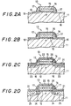
- an SiO 2 film 17 is deposited by atmospheric-pressure, low-temperature (about 410 o C) CVD using monosilane or the like.
- the SiO 2 film 17 is etched by RIE to form side walls of the gate electrode 13 using the SiO 2 film 17.
- Thermal oxidation is performed for the resultant structure respectively to form SiO 2 films 21 and 22 on the surfaces of the Si substrate 11 and the WSi x film 15.
- the SiO 2 film 21 is used for preventing a decrease in gate breakdown voltage at the edge of the gate electrode 13.
- arsenic ions 23 for forming an n + type region for a source/drain region are implanted in the Si substrate 11 using the gate electrode 13 and the SiO 2 film 17 as masks.
- annealing is performed to the resultant structure to form n - type regions 24 and n + type regions 25 serving as source/drain regions.
- the thermal oxidation for forming the SiO 2 films 21 and 22 is performed at a temperature within the range of 850°C to 900 o C.
- a temperature within the range of 850°C to 900 o C.
- the junction depth is undesirably increased. Therefore, since the thermal oxidation cannot be sufficiently performed, each of the SiO 2 films 21 and 22 has a thickness of about 10 nm.
- the SiO 2 film 21 When the SiO 2 film 21 has such a small thickness, the Si substrate 11 is substantially damaged during ion implantation of the arsenic 23. Therefore, crystal defects easily occur in the Si substrate 11. For this reason, degradation in device characteristics such as an increase in leakage current through a junction occurs, and the production yield is decreased.
- the SiO 2 films 21 and 22 are difficult to grow. For this reason, the thickness of the SiO 2 film 21 is small, and the above problem of easy formation of crystal defects in the Si substrate 11 typically occurs.
- a method of manufacturing an MIS semiconductor device comprising the steps of:
- the surface is oxidized. Therefore, upon formation of the second impurity region having a relatively high impurity concentration in the semiconductor substrate, the semiconductor substrate is only slightly damaged even if the oxide layer is thin, and crystal defects tend not be formed in the semiconductor substrate.
- the oxide layer is formed in addition to the first SiO 2 film (insulating film), a decrease in gate breakdown voltage at the edge portion of a gate electrode can be prevented.
- an SiO 2 film 12 As shown in Figure 2A, an SiO 2 film 12, a polycrystalline Si film 14 and a WSi x film 15 are formed on an Si substrate 11, and phosphorus ions 16 are implanted in the Si substrate 11.
- the same procedures as in Figures 1A to 1C are performed until an SiO 2 film 17 is formed on the Si substrate 11.
- an SiO 2 film 26 having a thickness of 10 to 30 nm is deposited on the surfaces of the Si substrate 11 and the WSi x film 15 by low-pressure, high-temperature (about 700°C) CVD using TEOS (tetraethylorthosilicate) or the like. With this CVD, the deposition rate can be decreased. Therefore, the SiO 2 film 26 having a small thickness can be deposited with good controllability.
- TEOS tetraethylorthosilicate
- the SiO 2 film 26 is formed in addition to the SiO 2 film 21, even if the SiO 2 film 21 has a small thickness of about 10 nm as shown in Figures 1A to 1D, the Si substrate 11 is only slightly damaged during implantation of the arsenic ions 23. Therefore, crystal defects tend not to occur in the Si substrate 11. Thus an MIS semiconductor device having excellent characteristics can be manufactured at a high yield.
- the WSi x film 15 in an amorphous state is crystallized by heat generated during formation of the SiO 2 films 21 and 22, and the protection capability of the WSi x film 15 against ion implantation is degraded. Therefore, when only the SiO 2 film 22 having the thickness of about 10 nm is formed on the surface of the WSi x film 15 like in Figure 1B or 1C, the arsenic ions 23 easily reach a channel portion through the gate electrode 13 during implantation of the arsenic ions 23.
- the SiO 2 film 26 is formed on the WSi x film 45. Therefore, the arsenic ions 23 cannot reach the channel portion through the gate electrode 13. Since the temperature of the low-pressure, high-temperature CVD for forming the SiO 2 film 26 is lower than that of thermal oxidation, junction depth is not increased even when the SiO 2 film 26 is formed.
- the second embodiment has substantially the same steps as in the first embodiment, except that SiO 2 films 17 serving as the side walls of a gate electrode 13 are formed by low-pressure, high-temperature CVD using TEOS or the like, and an SiO 2 film 26 is formed by atmospheric-pressure, low-temperature CVD.
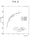
- step coverage of the SiO 2 film 17 is good at a low-density pattern region such as a peripheral circuit portion, but is poor at a high-density pattern region such as a memory cell.
- Figure 3 shows the step coverage of the SiO 2 film 17.
- the RIE must be performed until the SiO 2 film 17 is removed from the surface of the Si substrate 11 except for the side walls of the gate electrode 13, even in the peripheral circuit portion.
- the memory cell is excessively over-etched. When such over-etching occurs, the Si substrate 11 is frequently damaged. Therefore, crystal defects easily occur in the Si substrate 11 resulting in an inferior memory cell.
- the SiO 2 film 17 is formed by low-pressure, high-temperature CVD using TEOS or the like, the SiO 2 film 17 has good step coverage even in a high-density pattern region.
- an MIS semiconductor device having more excellent characteristics than those of the first embodiment can be manufactured at a higher yield than the first embodiment.
- both the SiO 2 films 17 and 26 are formed by low-pressure, high temperature CVD, the WSi x film 15 is heated twice to a high temperature of 600 o C or more while the WSi x film 15 is exposed, thereby easily peeling the WSi x film 15 from a polycrystalline Si film 14.
- the SiO 2 film 26 is formed by atmospheric-pressure, low-temperature CVD, the WSi x film 15 is not peeled from the polycrystalline Si film 14.
- a semiconductor device is manufactured following substantially the same procedures as in the second embodiment except that, when an SiO 2 film 17 is not left on the surface of an Si substrate 11 in a high-density pattern region such as a memory cell except for the side walls of a gate electrode 13, RIE applied to the SiO 2 film 17 is stopped and the SiO 2 film 17 remaining in a low-density pattern region such as a peripheral circuit portion at this time is removed by post wet etching. A stop time of the RIE applied to the memory cell or the like can be detected using an end point detector for etching.
- the Si substrate 11 is not damaged.
- the etching amount is about several tens of nm, the shapes of the SiO 2 films 17 of the side walls of the gate electrode 13 are almost not affected.
- an MIS semiconductor device having more excellent characteristics than those of the second embodiment can be manufactured at a yield higher that the second embodiment.
- cavities are undesirably formed in the shoulder portions of the SiO 2 film 17.
- a memory device having a memory cell in which each interval between gate electrodes 13 falls within the range of 1.4 to 3.6 ⁇ m and a peripheral circuit portion in which each interval between gate electrodes 13 is more than 3.6 ⁇ m is manufactured.
- an SiO 2 film 17 is deposited by atmospheric-pressure, low-temperature CVD using monosilane or the like, and RIE applied to the SiO 2 film 17 is absent in a 3.6 ⁇ m interval between the gate electrodes 13 on the surface of an Si substrate 11, except for the side walls of the gate electrode 13.
- the memory cell is masked by a resist film.
- the RIE is started again.
Claims (6)
- Procédé de fabrication d'un dispositif à semi-conducteur MIS, le procédé comprenant les étapes :de formation d'une électrode de grille (13) sur un film (12) d'isolation de grille sur un substrat (11) semi-conducteur de silicium ;de formation dans ledit substrat (11), en utilisant comme masque ladite électrode de grille (13), d'une première zone d'impureté (24) ayant une concentration d'impureté relativement basse ;de formation de parois latérales (17) sur ladite électrode de grille (13);de formation d'un premier film (26) de SiO2 pour recouvrir les surfaces dénudées dudit substrat (11), lesdites parois latérales (17) et ladite électrode de grille (13) ;d'oxydation d'au moins la surface dudit premier film (26) de SiO2 sur ledit substrat (11) pour former un second film (21) de SiO2 sur le premier film (26) de SiO2 ; etde formation dans ledit substrat (11), en utilisant comme masques ladite électrode de grille (13) et lesdites parois latérales (17) recouvertes par ledit premier film (26) de SiO2, d'une seconde zone d'impureté (25) ayant une concentration d'impureté relativement forte.
- Procédé selon la revendication 1, dans lequel l'épaisseur dudit premier film (26) de SiO2 tombe à l'intérieur d'une fourchette de 10 à 30 nm et l'épaisseur dudit second film (21) de SiO2 est d'environ 10 nm.
- Procédé selon la revendication 2, dans lequel lesdites parois latérales (17) sont faites à partir d'un film (17) de SiO2 déposé par CVD (dépôt chimique en phase vapeur) à la pression atmosphérique, à basse température, utilisant du monosilane, pour recouvrir les surfaces dudit substrat (11) et de ladite électrode de grille (13), et dans lequel le premier film (26) de SiO2 est déposé par CVD à basse pression, haute température, en utilisant un tétraéthylorthosilicate.
- Procédé selon la revendication 3, dans lequel, pour former lesdites parois latérales (17), ledit film (17) de SiO2 est partiellement éliminé par attaque par ions réactifs pour dénuder au moins une partie dudit substrat (11) ;dans lequel une couche de revêtement est formée sur une zone où ledit substrat (11) est dénudé ; etdans lequel ledit film (17) de SiO2 déposé est éliminé davantage par attaque par ions réactifs en utilisant ladite couche de revêtement comme masque pour former lesdites parois latérales (17).
- Procédé selon la revendication 2, dans lequel lesdites parois latérales sont faites à partir d'un film (17) de SiO2 déposé par CVD à basse pression haute température en utilisant du tétraéthylorthosilicate, pour recouvrir les surfaces de ladite électrode de grille (13) et dudit substrat (11), et dans lequel le premier film (26) de SiO2 est déposé par CVD à la pression atmosphérique, à basse température, en utilisant du monosilane.
- Procédé selon la revendication 5, dans lequel, pour former lesdites parois latérales (17), ledit film (17) de SiO2 est partiellement éliminé par attaque par ions réactifs pour dénuder au moins une partie dudit substrat (11); et dans lequel ledit film (17) de SiO2 déposé est éliminé davantage par attaque humide pour former lesdites parois latérales (17).
Applications Claiming Priority (2)
| Application Number | Priority Date | Filing Date | Title |
|---|---|---|---|
| JP185759/89 | 1989-07-18 | ||
| JP1185759A JP2760068B2 (ja) | 1989-07-18 | 1989-07-18 | Mis型半導体装置の製造方法 |
Publications (3)
| Publication Number | Publication Date |
|---|---|
| EP0409561A2 EP0409561A2 (fr) | 1991-01-23 |
| EP0409561A3 EP0409561A3 (en) | 1991-04-10 |
| EP0409561B1 true EP0409561B1 (fr) | 1997-09-17 |
Family
ID=16176374
Family Applications (1)
| Application Number | Title | Priority Date | Filing Date |
|---|---|---|---|
| EP90307802A Expired - Lifetime EP0409561B1 (fr) | 1989-07-18 | 1990-07-17 | Méthodes de fabrication d'éléments semi-conducteurs du type MIS |
Country Status (4)
| Country | Link |
|---|---|
| US (1) | US5073514A (fr) |
| EP (1) | EP0409561B1 (fr) |
| JP (1) | JP2760068B2 (fr) |
| DE (1) | DE69031447T2 (fr) |
Families Citing this family (37)
| Publication number | Priority date | Publication date | Assignee | Title |
|---|---|---|---|---|
| US5258319A (en) * | 1988-02-19 | 1993-11-02 | Mitsubishi Denki Kabushiki Kaisha | Method of manufacturing a MOS type field effect transistor using an oblique ion implantation step |
| US5298446A (en) * | 1990-02-20 | 1994-03-29 | Sharp Kabushiki Kaisha | Process for producing semiconductor device |
| KR950000141B1 (ko) * | 1990-04-03 | 1995-01-10 | 미쓰비시 뎅끼 가부시끼가이샤 | 반도체 장치 및 그 제조방법 |
| EP0469791A1 (fr) * | 1990-08-02 | 1992-02-05 | AT&T Corp. | Oxydes solubles pour circuits intégrés |
| US5214305A (en) * | 1990-08-28 | 1993-05-25 | United Microelectronics Corporation | Polycide gate MOSFET for integrated circuits |
| US5234850A (en) * | 1990-09-04 | 1993-08-10 | Industrial Technology Research Institute | Method of fabricating a nitride capped MOSFET for integrated circuits |
| US5221632A (en) * | 1990-10-31 | 1993-06-22 | Matsushita Electric Industrial Co., Ltd. | Method of proudcing a MIS transistor |
| JP2817393B2 (ja) * | 1990-11-14 | 1998-10-30 | 日本電気株式会社 | 半導体記憶装置の製造方法 |
| US5166087A (en) * | 1991-01-16 | 1992-11-24 | Sharp Kabushiki Kaisha | Method of fabricating semiconductor element having lightly doped drain (ldd) without using sidewalls |
| JP3104271B2 (ja) * | 1991-03-27 | 2000-10-30 | 松下電器産業株式会社 | イオン注入を用いた半導体装置の製造方法 |
| US5225357A (en) * | 1992-01-02 | 1993-07-06 | Chartered Semiconductor Manufacturing | Low P+ contact resistance formation by double implant |
| JPH06181219A (ja) * | 1992-12-15 | 1994-06-28 | Kawasaki Steel Corp | 半導体装置の製造方法 |
| US5391508A (en) * | 1992-12-21 | 1995-02-21 | Sharp Kabushiki Kaisha | Method of forming semiconductor transistor devices |
| US5308780A (en) * | 1993-07-22 | 1994-05-03 | United Microelectronics Corporation | Surface counter-doped N-LDD for high hot carrier reliability |
| US5372957A (en) * | 1993-07-22 | 1994-12-13 | Taiwan Semiconductor Manufacturing Company | Multiple tilted angle ion implantation MOSFET method |
| US5496747A (en) * | 1993-08-02 | 1996-03-05 | United Microelectronics Corporation | Split-gate process for non-volatile memory |
| US5432106A (en) * | 1993-08-02 | 1995-07-11 | United Microelectronics Corporation | Manufacture of an asymmetric non-volatile memory cell |
| US5334543A (en) * | 1993-10-28 | 1994-08-02 | United Microelectronics Corporation | Method of making reverse lightly doped drain (LDD) for buried N+ conductor |
| US5389565A (en) * | 1994-01-07 | 1995-02-14 | Zilog, Inc. | Method of fabricating high threshold metal oxide silicon read-only-memory transistors |
| US5786247A (en) | 1994-05-06 | 1998-07-28 | Vlsi Technology, Inc. | Low voltage CMOS process with individually adjustable LDD spacers |
| US5413945A (en) * | 1994-08-12 | 1995-05-09 | United Micro Electronics Corporation | Blanket N-LDD implantation for sub-micron MOS device manufacturing |
| US5700728A (en) * | 1994-11-07 | 1997-12-23 | United Microelectronics Corporation | Method of forming an MNOS/MONOS by employing large tilt angle ion implantation underneath the field oxide |
| US5498555A (en) * | 1994-11-07 | 1996-03-12 | United Microelectronics Corporation | Method of making LDD with polysilicon and dielectric spacers |
| US5472896A (en) * | 1994-11-14 | 1995-12-05 | United Microelectronics Corp. | Method for fabricating polycide gate MOSFET devices |
| US5518942A (en) * | 1995-02-22 | 1996-05-21 | Alliance Semiconductor Corporation | Method of making flash EPROM cell having improved erase characteristics by using a tilt angle implant |
| US5874340A (en) * | 1996-07-17 | 1999-02-23 | Advanced Micro Devices, Inc. | Method for fabrication of a non-symmetrical transistor with sequentially formed gate electrode sidewalls |
| US6051471A (en) * | 1996-09-03 | 2000-04-18 | Advanced Micro Devices, Inc. | Method for making asymmetrical N-channel and symmetrical P-channel devices |
| US5877050A (en) * | 1996-09-03 | 1999-03-02 | Advanced Micro Devices, Inc. | Method of making N-channel and P-channel devices using two tube anneals and two rapid thermal anneals |
| US5648286A (en) * | 1996-09-03 | 1997-07-15 | Advanced Micro Devices, Inc. | Method of making asymmetrical transistor with lightly doped drain region, heavily doped source and drain regions, and ultra-heavily doped source region |
| US5677224A (en) | 1996-09-03 | 1997-10-14 | Advanced Micro Devices, Inc. | Method of making asymmetrical N-channel and P-channel devices |
| TW304278B (en) * | 1996-09-17 | 1997-05-01 | Nat Science Council | The source-drain distributed implantation method |
| US6027978A (en) * | 1997-01-28 | 2000-02-22 | Advanced Micro Devices, Inc. | Method of making an IGFET with a non-uniform lateral doping profile in the channel region |
| US5923982A (en) * | 1997-04-21 | 1999-07-13 | Advanced Micro Devices, Inc. | Method of making asymmetrical transistor with lightly and heavily doped drain regions and ultra-heavily doped source region using two source/drain implant steps |
| US6004849A (en) * | 1997-08-15 | 1999-12-21 | Advanced Micro Devices, Inc. | Method of making an asymmetrical IGFET with a silicide contact on the drain without a silicide contact on the source |
| US5904529A (en) * | 1997-08-25 | 1999-05-18 | Advanced Micro Devices, Inc. | Method of making an asymmetrical IGFET and providing a field dielectric between active regions of a semiconductor substrate |
| US6096588A (en) * | 1997-11-01 | 2000-08-01 | Advanced Micro Devices, Inc. | Method of making transistor with selectively doped channel region for threshold voltage control |
| KR100423904B1 (ko) * | 2002-03-26 | 2004-03-22 | 삼성전자주식회사 | 모스 트랜지스터에 접속되는 콘택을 가진 반도체 장치의제조방법 |
Family Cites Families (27)
| Publication number | Priority date | Publication date | Assignee | Title |
|---|---|---|---|---|
| JPS52156576A (en) * | 1976-06-23 | 1977-12-27 | Hitachi Ltd | Production of mis semiconductor device |
| JPS5368581A (en) * | 1976-12-01 | 1978-06-19 | Hitachi Ltd | Semiconductor device |
| JPS6038030B2 (ja) * | 1977-09-28 | 1985-08-29 | 富士通株式会社 | Mis集積回路装置の製造方法 |
| US4356623A (en) * | 1980-09-15 | 1982-11-02 | Texas Instruments Incorporated | Fabrication of submicron semiconductor devices |
| JPS5773975A (en) * | 1980-10-27 | 1982-05-08 | Toshiba Corp | Mis type field effect transistor and manufacture thereof |
| JPS5893279A (ja) * | 1981-11-30 | 1983-06-02 | Fujitsu Ltd | 半導体装置の製造方法 |
| US4419809A (en) * | 1981-12-30 | 1983-12-13 | International Business Machines Corporation | Fabrication process of sub-micrometer channel length MOSFETs |
| JPS5961185A (ja) * | 1982-09-30 | 1984-04-07 | Fujitsu Ltd | Mis電界効果半導体装置の製造方法 |
| JPS59119870A (ja) * | 1982-12-27 | 1984-07-11 | Fujitsu Ltd | 半導体装置の製造方法 |
| JPS59138379A (ja) * | 1983-01-27 | 1984-08-08 | Toshiba Corp | 半導体装置の製造方法 |
| JPS59144175A (ja) * | 1983-02-07 | 1984-08-18 | Mitsubishi Electric Corp | 電界効果トランジスタの製造方法 |
| JPS59231864A (ja) * | 1983-06-15 | 1984-12-26 | Hitachi Ltd | 半導体装置 |
| JPS60136376A (ja) * | 1983-12-26 | 1985-07-19 | Hitachi Ltd | 半導体装置の製造方法 |
| JPS60241267A (ja) * | 1984-05-16 | 1985-11-30 | Hitachi Ltd | 半導体装置の製造方法 |
| US4642878A (en) * | 1984-08-28 | 1987-02-17 | Kabushiki Kaisha Toshiba | Method of making MOS device by sequentially depositing an oxidizable layer and a masking second layer over gated device regions |
| JPS62113474A (ja) * | 1985-11-13 | 1987-05-25 | Toshiba Corp | 半導体集積回路の製造方法 |
| JPS62245671A (ja) * | 1986-04-18 | 1987-10-26 | Hitachi Ltd | 半導体集積回路装置の製造方法 |
| US4771012A (en) * | 1986-06-13 | 1988-09-13 | Matsushita Electric Industrial Co., Ltd. | Method of making symmetrically controlled implanted regions using rotational angle of the substrate |
| JPS6341019A (ja) * | 1986-08-07 | 1988-02-22 | Matsushita Electronics Corp | イオン注入方法 |
| US4744859A (en) * | 1986-10-23 | 1988-05-17 | Vitelic Corporation | Process for fabricating lightly doped drain MOS devices |
| US4746624A (en) * | 1986-10-31 | 1988-05-24 | Hewlett-Packard Company | Method for making an LDD MOSFET with a shifted buried layer and a blocking region |
| US4728617A (en) * | 1986-11-04 | 1988-03-01 | Intel Corporation | Method of fabricating a MOSFET with graded source and drain regions |
| JPS63245921A (ja) * | 1987-04-01 | 1988-10-13 | Mitsubishi Electric Corp | バイポ−ラ型半導体装置の製造方法 |
| JPS6421919A (en) * | 1987-07-16 | 1989-01-25 | Nec Corp | Manufacture of semiconductor device |
| JPS6487923A (en) * | 1987-09-30 | 1989-04-03 | Iseki Agricult Mach | Shaft joint device |
| US4818714A (en) * | 1987-12-02 | 1989-04-04 | Advanced Micro Devices, Inc. | Method of making a high performance MOS device having LDD regions with graded junctions |
| JP2668538B2 (ja) * | 1988-02-05 | 1997-10-27 | ヤマハ株式会社 | 集積回路装置の製法 |
-
1989
- 1989-07-18 JP JP1185759A patent/JP2760068B2/ja not_active Expired - Lifetime
-
1990
- 1990-07-17 DE DE69031447T patent/DE69031447T2/de not_active Expired - Lifetime
- 1990-07-17 US US07/553,393 patent/US5073514A/en not_active Expired - Lifetime
- 1990-07-17 EP EP90307802A patent/EP0409561B1/fr not_active Expired - Lifetime
Non-Patent Citations (1)
| Title |
|---|
| Monthly Semiconductor World, February 1987, pages 94-100. * |
Also Published As
| Publication number | Publication date |
|---|---|
| EP0409561A2 (fr) | 1991-01-23 |
| US5073514A (en) | 1991-12-17 |
| DE69031447T2 (de) | 1998-02-12 |
| EP0409561A3 (en) | 1991-04-10 |
| JP2760068B2 (ja) | 1998-05-28 |
| JPH0350740A (ja) | 1991-03-05 |
| DE69031447D1 (de) | 1997-10-23 |
Similar Documents
| Publication | Publication Date | Title |
|---|---|---|
| EP0409561B1 (fr) | Méthodes de fabrication d'éléments semi-conducteurs du type MIS | |
| US5438009A (en) | Method of fabrication of MOSFET device with buried bit line | |
| US5780330A (en) | Selective diffusion process for forming both n-type and p-type gates with a single masking step | |
| EP0054163B1 (fr) | Procédé de fabrication d'un contact électrique sur un substrat en silicium à travers une couche relativement mince de dioxyde de silicium formée sur la surface du substrat et procédé pour la fabrication d'un transistor à effet de champ | |
| US6541823B1 (en) | Semiconductor device including multiple field effect transistors and manufacturing method thereof | |
| GB2128807A (en) | Improvements in or relating to a method for fabricating an MOS device | |
| KR19990036772A (ko) | 트렌치 격리구조를 갖는 전계효과 트랜지스터 및 그 제조방법 | |
| US6582998B2 (en) | Method for fabricating nonvolatile semiconductor memory device | |
| EP0032030B1 (fr) | Dispositif semi-conducteur et procédé de fabrication d'un dispositif semi-conducteur | |
| US4450021A (en) | Mask diffusion process for forming Zener diode or complementary field effect transistors | |
| EP0195902B1 (fr) | Structure à double injection d'électrons et procédé utilisant une barrière automatique contre l'oxydation | |
| KR0157875B1 (ko) | 반도체 장치의 제조방법 | |
| EP0158715B1 (fr) | Procédé pour la fabrication de dispositifs semi-conducteurs comportant une étape de recuit à haute température dans une atmosphère oxydante | |
| KR20000021503A (ko) | 플래쉬 메모리 소자의 제조방법 | |
| US5292684A (en) | Semiconductor device with improved contact and method of making the same | |
| US6100140A (en) | Manufacturing method of semiconductor device | |
| US6316804B1 (en) | Oxygen implant self-aligned, floating gate and isolation structure | |
| US4653173A (en) | Method of manufacturing an insulated gate field effect device | |
| KR100439770B1 (ko) | 반도체 장치의 제조방법 | |
| KR970011138B1 (ko) | 모스 트랜지스터의 제조방법 | |
| KR960006689B1 (ko) | 반도체소자의 ldd 제조방법 | |
| KR100338090B1 (ko) | 반도체소자의제조방법 | |
| KR0155796B1 (ko) | 얇은 접합을 갖는 트랜지스터 및 그 제조방법 | |
| JPH04165629A (ja) | Mos型半導体装置 | |
| KR970002428B1 (ko) | 반도체소자 제조방법 |
Legal Events
| Date | Code | Title | Description |
|---|---|---|---|
| PUAI | Public reference made under article 153(3) epc to a published international application that has entered the european phase |
Free format text: ORIGINAL CODE: 0009012 |
|
| AK | Designated contracting states |
Kind code of ref document: A2 Designated state(s): DE FR GB |
|
| PUAL | Search report despatched |
Free format text: ORIGINAL CODE: 0009013 |
|
| AK | Designated contracting states |
Kind code of ref document: A3 Designated state(s): DE FR GB |
|
| 17P | Request for examination filed |
Effective date: 19910816 |
|
| 17Q | First examination report despatched |
Effective date: 19940810 |
|
| GRAG | Despatch of communication of intention to grant |
Free format text: ORIGINAL CODE: EPIDOS AGRA |
|
| GRAH | Despatch of communication of intention to grant a patent |
Free format text: ORIGINAL CODE: EPIDOS IGRA |
|
| GRAH | Despatch of communication of intention to grant a patent |
Free format text: ORIGINAL CODE: EPIDOS IGRA |
|
| GRAA | (expected) grant |
Free format text: ORIGINAL CODE: 0009210 |
|
| AK | Designated contracting states |
Kind code of ref document: B1 Designated state(s): DE FR GB |
|
| REF | Corresponds to: |
Ref document number: 69031447 Country of ref document: DE Date of ref document: 19971023 |
|
| ET | Fr: translation filed | ||
| PLBE | No opposition filed within time limit |
Free format text: ORIGINAL CODE: 0009261 |
|
| STAA | Information on the status of an ep patent application or granted ep patent |
Free format text: STATUS: NO OPPOSITION FILED WITHIN TIME LIMIT |
|
| 26N | No opposition filed | ||
| REG | Reference to a national code |
Ref country code: GB Ref legal event code: IF02 |
|
| PGFP | Annual fee paid to national office [announced via postgrant information from national office to epo] |
Ref country code: FR Payment date: 20090710 Year of fee payment: 20 |
|
| PGFP | Annual fee paid to national office [announced via postgrant information from national office to epo] |
Ref country code: DE Payment date: 20090709 Year of fee payment: 20 Ref country code: GB Payment date: 20090715 Year of fee payment: 20 |
|
| REG | Reference to a national code |
Ref country code: GB Ref legal event code: PE20 Expiry date: 20100716 |
|
| PG25 | Lapsed in a contracting state [announced via postgrant information from national office to epo] |
Ref country code: GB Free format text: LAPSE BECAUSE OF EXPIRATION OF PROTECTION Effective date: 20100716 |
|
| PG25 | Lapsed in a contracting state [announced via postgrant information from national office to epo] |
Ref country code: DE Free format text: LAPSE BECAUSE OF EXPIRATION OF PROTECTION Effective date: 20100717 |