EP0405437A1 - Schlupfregelsystem für ein Kraftfahrzeug - Google Patents
Schlupfregelsystem für ein Kraftfahrzeug Download PDFInfo
- Publication number
- EP0405437A1 EP0405437A1 EP90112114A EP90112114A EP0405437A1 EP 0405437 A1 EP0405437 A1 EP 0405437A1 EP 90112114 A EP90112114 A EP 90112114A EP 90112114 A EP90112114 A EP 90112114A EP 0405437 A1 EP0405437 A1 EP 0405437A1
- Authority
- EP
- European Patent Office
- Prior art keywords
- slip
- slip control
- control system
- value
- torque
- Prior art date
- Legal status (The legal status is an assumption and is not a legal conclusion. Google has not performed a legal analysis and makes no representation as to the accuracy of the status listed.)
- Granted
Links
Images


Classifications
-
- F—MECHANICAL ENGINEERING; LIGHTING; HEATING; WEAPONS; BLASTING
- F16—ENGINEERING ELEMENTS AND UNITS; GENERAL MEASURES FOR PRODUCING AND MAINTAINING EFFECTIVE FUNCTIONING OF MACHINES OR INSTALLATIONS; THERMAL INSULATION IN GENERAL
- F16H—GEARING
- F16H61/00—Control functions within control units of change-speed- or reversing-gearings for conveying rotary motion ; Control of exclusively fluid gearing, friction gearing, gearings with endless flexible members or other particular types of gearing
- F16H61/14—Control of torque converter lock-up clutches
- F16H61/143—Control of torque converter lock-up clutches using electric control means
-
- B—PERFORMING OPERATIONS; TRANSPORTING
- B60—VEHICLES IN GENERAL
- B60K—ARRANGEMENT OR MOUNTING OF PROPULSION UNITS OR OF TRANSMISSIONS IN VEHICLES; ARRANGEMENT OR MOUNTING OF PLURAL DIVERSE PRIME-MOVERS IN VEHICLES; AUXILIARY DRIVES FOR VEHICLES; INSTRUMENTATION OR DASHBOARDS FOR VEHICLES; ARRANGEMENTS IN CONNECTION WITH COOLING, AIR INTAKE, GAS EXHAUST OR FUEL SUPPLY OF PROPULSION UNITS IN VEHICLES
- B60K28/00—Safety devices for propulsion-unit control, specially adapted for, or arranged in, vehicles, e.g. preventing fuel supply or ignition in the event of potentially dangerous conditions
- B60K28/10—Safety devices for propulsion-unit control, specially adapted for, or arranged in, vehicles, e.g. preventing fuel supply or ignition in the event of potentially dangerous conditions responsive to conditions relating to the vehicle
- B60K28/16—Safety devices for propulsion-unit control, specially adapted for, or arranged in, vehicles, e.g. preventing fuel supply or ignition in the event of potentially dangerous conditions responsive to conditions relating to the vehicle responsive to, or preventing, spinning or skidding of wheels
- B60K28/165—Safety devices for propulsion-unit control, specially adapted for, or arranged in, vehicles, e.g. preventing fuel supply or ignition in the event of potentially dangerous conditions responsive to conditions relating to the vehicle responsive to, or preventing, spinning or skidding of wheels acting on elements of the vehicle drive train other than the propulsion unit and brakes, e.g. transmission, clutch, differential
-
- F—MECHANICAL ENGINEERING; LIGHTING; HEATING; WEAPONS; BLASTING
- F16—ENGINEERING ELEMENTS AND UNITS; GENERAL MEASURES FOR PRODUCING AND MAINTAINING EFFECTIVE FUNCTIONING OF MACHINES OR INSTALLATIONS; THERMAL INSULATION IN GENERAL
- F16H—GEARING
- F16H59/00—Control inputs to control units of change-speed- or reversing-gearings for conveying rotary motion
- F16H59/50—Inputs being a function of the status of the machine, e.g. position of doors or safety belts
- F16H2059/506—Wheel slip
-
- F—MECHANICAL ENGINEERING; LIGHTING; HEATING; WEAPONS; BLASTING
- F16—ENGINEERING ELEMENTS AND UNITS; GENERAL MEASURES FOR PRODUCING AND MAINTAINING EFFECTIVE FUNCTIONING OF MACHINES OR INSTALLATIONS; THERMAL INSULATION IN GENERAL
- F16H—GEARING
- F16H59/00—Control inputs to control units of change-speed- or reversing-gearings for conveying rotary motion
- F16H59/60—Inputs being a function of ambient conditions
- F16H59/66—Road conditions, e.g. slope, slippery
Definitions
- the present invention relates to a slip control system for a vehicle and, more particularly, to a slip control system for the vehicle, adapted to prevent a slip of the driven wheels on a road surface from becoming excessive.
- Prevention of a slip of the driven wheels from becoming excessive at the time of accelerating or the like is effective in order to efficiently provide a propulsive force of the vehicle as well as to provide safety in terms of prevention of a spin of the vehicle body and so on.
- torque to be applied to the driven wheels as a cause of slipping may be reduced.
- Slip control of this type is disclosed, for example, in Japanese Patent Unexamined Publication (kokai) Nos. 16,948/1983 and 56,662/1985. Further, Japanese Patent Unexamined Publication (kokai) No. 231,836/1987 discloses a vehicle equipped with a torque converter having a lockup clutch interposed between an engine and a driven wheel, in which the lockup clutch is arranged so as to be forcibly uncoupled during slip control.
- the torque converter in instances where the lockup clutch is uncoupled during the slip control, can reduce its efficiency of transmission of torque to the driven wheel by a portion at which the torque converter slips, and it can reduce a shock resulting from a variation in torque to be applied to the driven wheel due to its fluid buffer action, such a variation being caused by the slip control.
- the slip control system of this type wherein the lockup clutch is uncoupled during slip control may be likely to cause the problem that a large extent of a slip may occur again immediately after the end of the slip control.
- torque to be applied to the driven wheel is temporarily increased due to no slip of the torque converter, thereby causing a large extent of a slip at the driven wheel again.
- This phenomenon may cause a hatching in which the startup and end of the slip control is frequently repeated as well as result in a frequent repetition of coupling and uncoupling the lockup clutch.
- the present invention has the object to provide a slip control system for a vehicle which can prevent a large degree of a slip of the driven wheel from occurring again due to the uncoupling of the lockup clutch after the end of the slip control, given the fact that the lockup clutch is forcibly uncoupled during the slip control.
- the present invention consists of a slip control system of a vehicle, comprising: a torque converter with a lockup clutch interposed between an engine and a driven wheel; a lockup clutch control means for controlling the lockup clutch so as to be coupled or uncoupled on the basis of a predetermined lockup characteristic; a torque adjusting means for adjusting a torque to be applied to the driven wheel; a slip detecting means for detecting a slip value of the driven wheel against a road surface; a slip control means for controlling a slip by reducing the torque to be applied to the driven wheel by controlling the torque adjusting means when the slip value detected by the slip detecting means is equal to or greater than a given value; a lockup-clutch uncoupling means for uncoupling the lockup clutch prior to the predetermined lockup characteristic when slip control is performed by the slip control means; and a delay means for maintaining a state for a given period of time from end of the slip control by the slip control means, in which the lockup clutch is uncoupled
- the present invention allows the lockup clutch to maintain its uncoupled state for a given period of time after the end of the slip control. Hence, even if the lockup clutch would be coupled on the basis of the lockup characteristic after the given period of time would have elapsed, the driven wheels do not cause any slip to a great extent again due to the coupling of the lockup clutch, because the slip value of the driven wheelsis brought into a sufficiently low level.
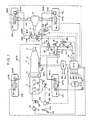
- an automobile A is shown to be of a rear wheel drive system in which a left-hand front wheel 1FL and a right-hand front wheel 1FR are undriven wheels, and a left-hand rear wheel 1RL and a right-hand rear wheel 1RR are driven.
- An engine 2 loaded on a front portion of the vehicle body generates torque that is then transmitted through an automatic transmission 3, a propeller shaft 4 and a differential gear 5 to a left-hand drive shaft 6L and then to the left-hand rear wheel 1RL, on the one hand, and to a right-hand drive shaft 6R and then to the right-hand rear wheel 1RR, on the other hand.
- the automatic transmission 3 comprises a torque converter 11 and a multiple shift geartrain 12.
- the multiple shift geartrain 12 is of a hydraulically operative type as is known to the skilled in the art.
- the geartrain has four forward speed ranges and one reverse speed range, for example, and is of the type that implements the gear shift by altering a combination of exciting and deenergizing a plurality of solenoids 13a mounted in its hydraulic pressure circuit.
- the torque converter 11 has a lockup clutch 11a of a hydraulically operative type and is coupled or uncoupled by altering a combination of energizing or deenergizing solenoids 13b incorporated in the hydraulic pressure circuit.
- the solenoids 13a and 13b are controlled by a control unit UAT for automatic transmission.
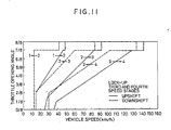
- the control unit UAT has stored a shift characteristic as a map 89 as shown in FIG. 11, thereby performing a shift, namely, upshifting or downshifting, on the basis of this shift characteristic.
- FIG. 11 also contains a lockup characteristic. In this embodiment, a lockup clutch is coupled at third and four speed stages, and the lockup clutch 11A is uncoupled at first and second speed stages.
- the control unit UAT receives a signal of throttle opening angle from a sensor 61 and a vehicle speed signal from a sensor 62 (in this embodiment, a signal of the number of revolutions of a propeller shaft 4) and output from a control unit UTR for traction or slip control as will be described hereinafter.
- the front wheels 1FR, 1FL and the rear wheels 1RR, 1RL are provided with brakes 21FR, 21FL, 21RR and 21RL, respectively.
- the wheels 1FR, 1FL, 1RR and 1RL have calipers (wheel cylinders) 22FR, 22FL, 22RR and 22RL to which braking liquid pressure is fed through pipes 23FR, 23FL, 23RR and 23RL, respectively.
- the construction for supplying the braking liquid pressure to each of the brakes 21FR, 21FL, 21RR and 21RL will be described as follows.
- the powder generated by depressing a brake pedal 25 is increased by a servo unit 26 of a liquid pressure servo type and transmitted to a master cylinder 27 of a tandem type.
- a servo unit 26 of a liquid pressure servo type is increased by a servo unit 26 of a liquid pressure servo type and transmitted to a master cylinder 27 of a tandem type.
- To a first exit 27a from the master cylinder 27 is connected the braking pipe 23FL for the left-hand front wheel.
- To a second exit 27b of the master cylinder 27 is connected the braking pipe 23FR for the right-hand front wheel.
- a branch passage 28a branched from the passage 28 is connected to a recombining section a , as will be described hereinafter, and a switching valve 32 of electromagnetic type is connected to the branch passage 28a.
- the liquid pressure generated by the servo unit 26 is fed to the recombining section a through a passage 33 which in turn is provided with a switching valve 34 of electromagnetic type.
- the passaage 33 is further provided with a one-way restrictor 35, disposed in parallel to the switching valve 34, so as to allow only a flow toward the recombining section a .
- braking passages 23RR and 23RL for the right-hand and left-hand rear wheels, respectively.
- switching valves 36A and 36A each of electromagnetic type, respectively, and another switching valves 36B and 37B are connected to respective relief passages 38L and 38R connected on the downstream sides of the respective valves 36A and 37A.
- valves 32, 34, 36A, 36B, 37A and 37B are controlled by the control unit UTR for slip control.
- the valve 32 is closed, the valve 34 is open, the valves 36A and 37A are open, and the valves 36B and 37B are closed, as shown in the drawing.
- the braking liquid pressure is fed through the master cylinder 27 to the brakes 21FR and 21FL for the front wheels, while the liquid pressure from the servo unit 26 is fed as braking liquid pressure through the passage 33 to the brakes 21RR and 21RL, respectively, in accordance with the power generated by depressing the brake pedal 25.
- the valve 34 is closed while the valve 32 is opened.
- the braking liquid pressure is retained, increased or decreased by duty control of the valve 36A and 36B (37A and 37B). More specifically, given the valve 32 being open, the braking liquid pressure is retained when the valves 36A, 36B, 37A and 37B are closed; it is increased when the valve 36A (37A) is open and the valve 36B (37B) is closed; and it is decreased when the valve 36A (37A) is closed while the valve 360 (37B)is open.
- the braking liquid pressure passed through the branch passage 28a is arranged so as not to act upon the brake pedal 25 as counterforce by means of the one-way refractor 35.
- the braking liquid pressure from the servo unit 26 is generated in accordance with the power generated by depressing the brake pedal and supplied to the brakes 21RR and 21RL for the rear wheels.
- the control unit UTR for slip control or traction control brakes the driven rear wheels 1RL and 1RR and reduces the torque to be generated by the engine in order to reduce the torque' applied to the driven rear wheels 1RL and 1RR.
- a throttle opening angle adjustment mechanism 44 is interposed within a connection mechanism of a throttle valve 42 disposed in an intake air passage 41 for the engine to an accelerator pedal 43.
- the throttle opening angle adjustment mechanism 44 will be described in conjunction with FIG. 2.
- the throttle opening angle adjustment mechanism 44 is shown to comprise three levers, i.e., first lever 112, second lever 113, and third lever 114, each of which is slidable in the left-hand and right-hand directions in the drawing.
- the first lever 112 is connected to the accelerator pedal 43 through an accelerator wire 112a and the second lever 113 is connected to the throttle valve 42 through a throttle wire 112t.
- the second lever 113 is arranged to be biased by a return spring 121 in the right direction in the drawing, namely, in a direction in which the throttle valve 42 is closed.
- the third lever 114 comprises a first engagement section 114a engageable with the first lever 112 from the right direction in the drawing and a second engagement section 114b engageable with the second lever 113 from the right direction in the drawing.
- a first spring 116 so as to bias the first engagement section 114a of the third lever 114 in a direction in which the first engagement section 114a is brought into abutment with the first lever 112.
- a second spring 122 so as to bias the second engagement section 114b thereof in a direction to allow the second engagement section 114b to come into abutment with the second lever 113.
- the biasing force of the first spring 116 is set to be larger than the biasing force of the second spring 122 and the return spring 121.
- the first lever 112 is provided with an engagement section 112b in its right position in the drawing, thereby regulating the second lever 113 from displacing in a predetermined distance toward the right direction relative to the first lever 112.
- a press lever 111 is disposed on the left side of the third lever 114 in the drawing, which is driven in the left and right directions in the drawing by means of a motor 106 and whose left direction beyond a predetermined distance is yet blocked by a stopper 123 which is arranged so as to abut with the press lever 111.
- FIGS. 2(a) and 2(b) thus providing a throttle opening angle in accordance with an accelerator opening angle.
- the throttle valve is opened at opening angles ranging from 0% to 100% as the accelerator opening angle ranges from 0% to 100%.
- FIG. 2(a) represents the throttle opening angle of 0% while the accelerator opening angle is 0%.
- FIG. 2(b) represents the throttle opening angle of 75% in accordance of a 75% accelerator opening angle.
- a clearance between the press lever 111 and the third lever 114 there is provided a clearance between the press lever 111 and the third lever 114, a clearance being set so as to vary from 0% to 100% with respect to the entire length of the clearance in accordance with the corresponding accelerator opening angle varying from 0% to 100%.
- the clearance accordingly is shortened by 75% - in other words, there is still remained a clearance accounting for 75% to 100% with the entire length therebetween. This can be said of whichever opening angle is.
- FIG. 2(c) represents the state in which the throttle opening angle is returned to a full closed state when the accelerator opening angle is 75%.
- the engagement section 112b is brought into abutment with the second lever 113.
- the full opening operation of the accelerator pedal can allow the throttle valve 42 to be opened at least to 25%.
- the press lever 111 would have been stuck in the state as shown in FIG. 2(C)
- the automobile could be driven by itself at the least to a tune-up factory or any other appropriate locations nearby.
- the spring 122 is no longer necessary. It is also noted that the lever 113 constituting the second lever and the lever 114 may be integrally constructed together with each other (in this case, however, they cannot take the status as shown in FIG. 2(d)).
- the control unit UTR for slip control implements brake control, engine control to be implemented by controlling the motor 106 for the throttle opening angle adjustment mechanism 44, and lockup control through a control unit UAT for shift control.
- the control unit UTR is provided with inputs of signals from the sensors 63, 64, 65 and 66 for sensing each of the wheel speeds, a signal of the throttle opening angle from a sensor 61, a signal of a vehicle speed from a sensor 62, a signal of the accelerator opening angle from the sensor 67, a signal of an opening angle for the motor 106 from a sensor 68, a signal of a steered angle of the steering wheel from a sensor 69, a mode signal from a switch 70 to be manually operable, and a brake signal from a brake switch 71 so as to be turned on when the brake pedal is depressed.
- FIG. 3 indicates the contents of the slip control with a focus on the engine control and the brake control.
- a target value for engine (a target slip value of the driven wheel) is represented by SET, while a target value for brake is represented by SBT (SBT > SET).
- the throttle opening angle corresponds to the accelerator opening angle.
- the throttle opening angle is represented by a basic throttle opening angle TH ⁇ B obtainable on the basis of the basic throttle characteristic as shown in FIG. 9.
- a slip occurs to such a large extent that a slip value of the driven wheel becomes the target value SET or higher.
- slip control is started when the slip value of the driven wheel becomes the target value SET or higher.
- the throttle opening angle is immediately reduced down to the lowest control value SM (feed-forward control).
- the opening angle of the throttle valve is subjected to feedback control so as to allow the slip value of the driven wheel to become the target value SET for engine.
- the braking liquid pressure is supplied to the brakes 21RR and 21RL of the driven wheels (so as to start up slip control by both the engine control and brake control).
- the braking liquid pressure is subjected to feedback control so as for the slip value of the driven wheel to reach the target value SBT for brake.
- condition in which the slip control is suspended is when the accelerator is closed to a full extent.
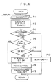
- step P1 signals from the sensors and switches are read.
- an actual slip value S for the driven wheel is calculated by subtracting a revolution speed VJ of the undriven wheel from a revolution speed VK of the driven wheel.
- the revolution speed VJ of the undriven wheel for the engine is used as an average of the revolution speeds of the left-hand and right-hand undriven wheels and the revolution speed VK of the driven wheel for the engine is used as a revolution speed of the left-hand driven wheel or the right-hand driven wheel, whichever larger, while the revolution speed VJ of the undriven wheel for the brake is the same as that for the engine and the revolution speed VK of the driven wheel for the brake is selected from individual revolution speeds of the left-hand and right-hand driven wheels, respectively (in this case, the braking power to the left-hand and right-hand driven wheels is controlled individually and independently).
- step P4 it is decided whether the accelerator is currently in a full closed state. If the decision at step P4 is NO, it is then decided at step P5 whether slip flag is set to 1. That the slip flag is set to 1 means that slip control is under way. If the decision at step P5 is NO, the flow proceeds to step P6 where it is further decided whether a slip value S for the driven wheel is equal to or greater than the target value SET for engine. If the decision is YES at step P6, the flow advances to step P7 where the slip flag is set to 1 and the lowest control value SM is set. After step P7, the flow proceeds to step P8. When the decision at step P5 is YES, the flow proceeds to step P8 without passage through steps P6 and P7.
- brake control is performed as will be described hereinafter.
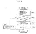
- the content of the brake control is to decide and realize the target value SBT for brake.
- step P9 the target value SET for engine is decided in a manner as will be described hereinafter, and a throttle opening angle (an opening angle of the motor 106) TH ⁇ M to be required for realization of this target value SET for engine is decided on the basis of a given formula for feedback control.
- the realization of the target value SET for engine, i.e., output of the throttle opening angle TH ⁇ M, is performed by interruption processing for throttle control as will be described hereinafter.
- slip control is suspended by resetting the slip flag to zero at step P10.
- FIG. 5 (Step P8 of FIG. 4)
- FIG. 6 (Step P9 of FIG. 4)
- step P3l it is decided whether it is the time when the slip flag has changed from zero to one, namely, it is the time t1 of FIG. 3. If the decision at step P31 is YES, on the one hand, the flow proceeds to step P32 where the final target throttle opening angle Tn (the motor opening angle) is set as the lowest control value SM to be decided as will be described hereinafter.
- Tn the motor opening angle
- step P3l If it is decided at step P3l that it is not the time when the slip flag has changed to one from zero, on the other hand, it is then decided at step P33 whether or not the slip flag is 1. If the decision at step P33 is YES, the flow proceeds to step P34 and the final target throttle opening angle Tn is set as the throttle opening angle THM to be decided at step P9 of FIG. 4.
- step P33 If the decision at step P33 is NO, this means that no slip control is performed so that the final target throttle opening angle Tn is set to 100 (the characteristic depending upon the accelerator opening angle, as shown in FIG. 9, is provided).
- the motor 106 is driven so as to generate the final target throttle opening angle Tn at step P36.
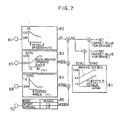
- FIG. 7 shows the block diagram illustrating the circuit for determining the target values SET and SBT for engine and for brake, respectively, in which the vehicle speed, the accelerator opening angle, the steered angle of a steering wheel, an operational status of the mode switch 70, and the maximum friction coefficient, ⁇ max, against the road surface are used as parameters.
- the basic value STAO of the target value SET for engine and the basic value STBO of the target value SBT for brake are stored in a map 81 using the maximum friction coefficient as a parameter (STAO ⁇ STBO). It is thus to be noted that the target values SET and SBT are obtained by multiplying the basic values STAO and STBO, respectively, by a correction gain coefficient KD.
- the correction gain coefficient KD is obtained by multiplying each of gain coefficients VG, ACPG, STRG and MODEG.
- the gain coefficient VG is determined by using the vehicle speed as a parameter and is stored as a map 82.
- the gain coefficient ACPG is determined by using the accelerator opening angle as a parameter and is stored as a map 83.
- the gain coefficient STRG is determined by using the steered angle of the steering wheel as a parameter and is stored as a map 84.
- the gain coefficient MODEG is selected manually by the operator and stored as a table 85 in which two modes comprised of sport mode and normal mode are set.
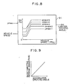
- the lowest control value SM is determined by using the vehicle speed and the maximum friction coefficient against the road surface as parameters and stored as a map 91, as shown in FIG. 8.
- the maximum friction coefficient against the road surface may manually be set by the operator, it may be estimated as follows.
- the maximum friction coefficient can be estimated in accordance with the magnitude of acceleration obtainable by subtracting the revolution speed of the undriven wheel after a predetermined time period elapsed from the time point t1 of FIG. 3 from the revolution speed of the undriven wheel at the time point t1. Further, it can be estimated on the basis of the maximum acceleration among the magnitudes of acceleration monitored on the basis of a variation in the revolution speed over the entire time period of the latest slip control.
- control content of the control unit UAT for the transmission is shown in FIG. 10.
- step Q1 the vehicle speed and the throttle opening angle are read and, then at step Q2, a shift judgment is performed whether to upshift or downshift on the basis of the shift characteristic as shown in FIG. 11. Further, at step Q3, a lockup judgment is performed whether or not to couple or uncouple the lockup clutch 11A on the basis of the lockup characteristics as shwon in FIG. 11, which can be used as the shift characteristic, too.
- step Q4 a shift judgment signal is generated to the solenoid 13a on the basis of the result from the shift judgment at step Q2.
- step Q5 it is decided whether the result from the lockup judgment at step Q3 indicates the coupling of the lockup clutch 11A. If the decision as step Q5 is YES, it is further judged at step Q6 whether or not slip flag is set to 1. When it is decided at step Q6 that the slip flag is set to 1, i.e., that the slip control is under way, it is inhibited at step Q7 that the lockup clutch 11A is coupled, prior to the judgment result at step Q3. In other words, the lockup clutch 11A is uncoupled at step Q7 Thereafter at step Q8, it is decided whether the slip flag is zero. When the decision at step Q8 is NO, it is decided that the slip control is still under way so that the flow proceeds to step Q7.
- step Q8 When it is decided at step Q8 that the slip flag is set to zero, the flow proceeds to step Q9 and it is decided therein whether or not the friction coefficient on a road surface (a maximum friction coefficient ⁇ max may also be utilized) is small. If the decision at step Q9 is YES, the inhibition of coupling the lockup clutch 11A is continued at step Q10. Then at step Q11, it is confirmed that a given period of time has elapsed since the time point when the slip flag has been turned to zero and, at step Q12, the coupling or uncoupling of the lockup clutch 11A is implemented according to the result of the lockup judgment at step Q3.
- step Q5 If the decision at step Q5, Q6 or Q9, the flow proceeds to step Q12.
- the given period of time may be set at step Q12 so as to vary with the friction coefficient ⁇ on a road surface.
- the given period of time may be set shorter when the friction coefficient ⁇ is great, while the given period of time may be set longer when the friction coeffi cient ⁇ is small.
- the setting of the given time period may be made in a stepwise manner or in a continuous manner.
- a control unit UIG is provided for controlling the spark timing of the engine.
- the control unit UIG is basically constructed so as to determine the spark timing on the basis of the signal of the throttle opening angle from the sensor 61 and the signal of the number of revolutions of the engine from the sensor 72.
- the spark timing decided is generated to an igniter 51 and the primary current of an ignition coil 52 is blocked at this spark timing.
- the secondary current of a high voltage generated by blocking the primary current is fed to a spark plug 54 through a distributer 53.
- the slip value of the driven wheel is represented by a variation between the revolution speeds of the undriven and driven wheels, however, the slip value may be represented by a ratio of the former to the latter. It is also to be noted that the slip control may be carried out by means of engine control only or brake control only.
Landscapes
- Engineering & Computer Science (AREA)
- General Engineering & Computer Science (AREA)
- Mechanical Engineering (AREA)
- Chemical & Material Sciences (AREA)
- Combustion & Propulsion (AREA)
- Transportation (AREA)
- Control Of Vehicle Engines Or Engines For Specific Uses (AREA)
- Control Of Fluid Gearings (AREA)
- Control Of Driving Devices And Active Controlling Of Vehicle (AREA)
- Regulating Braking Force (AREA)
Applications Claiming Priority (2)
| Application Number | Priority Date | Filing Date | Title |
|---|---|---|---|
| JP167994/89 | 1989-06-29 | ||
| JP1167994A JPH0333553A (ja) | 1989-06-29 | 1989-06-29 | 車両のスリップ制御装置 |
Publications (2)
| Publication Number | Publication Date |
|---|---|
| EP0405437A1 true EP0405437A1 (de) | 1991-01-02 |
| EP0405437B1 EP0405437B1 (de) | 1994-03-30 |
Family
ID=15859830
Family Applications (1)
| Application Number | Title | Priority Date | Filing Date |
|---|---|---|---|
| EP90112114A Expired - Lifetime EP0405437B1 (de) | 1989-06-29 | 1990-06-26 | Schlupfregelsystem für ein Kraftfahrzeug |
Country Status (4)
| Country | Link |
|---|---|
| US (1) | US5092435A (de) |
| EP (1) | EP0405437B1 (de) |
| JP (1) | JPH0333553A (de) |
| DE (1) | DE69007692T2 (de) |
Cited By (3)
| Publication number | Priority date | Publication date | Assignee | Title |
|---|---|---|---|---|
| EP0405438A3 (en) * | 1989-06-29 | 1991-06-19 | Mazda Motor Corporation | Slip control system for a vehicle |
| WO1998004852A1 (de) * | 1996-07-26 | 1998-02-05 | Zf Friedrichshafen Ag | Verfahren zur abstimmung des schaltzustandes einer wandlerüberbrückungskupplung bei einem automatikgetriebe |
| FR2780002A1 (fr) * | 1998-06-18 | 1999-12-24 | Mannesmann Sachs Ag | Systeme d'entrainement d'un vehicule |
Families Citing this family (13)
| Publication number | Priority date | Publication date | Assignee | Title |
|---|---|---|---|---|
| US5265705A (en) * | 1989-11-17 | 1993-11-30 | Kabushiki Kaisha Komatsu Seisakusho | Method of preventing wheel loader from slipping |
| DE4003866A1 (de) * | 1990-02-09 | 1991-08-14 | Man Nutzfahrzeuge Ag | Steuerung fuer die kupplung eines getriebes in einem kraftfahrzeug |
| JP2902055B2 (ja) * | 1990-06-07 | 1999-06-07 | マツダ株式会社 | 車両のトラクションコントロール装置 |
| DE4201146C2 (de) * | 1991-01-18 | 2003-01-30 | Hitachi Ltd | Vorrichtung zur Steuerung des Kraftfahrzeugverhaltens |
| JP3527778B2 (ja) * | 1994-07-13 | 2004-05-17 | ジヤトコ株式会社 | 車両のスリップ制御装置 |
| JPH0828687A (ja) * | 1994-07-21 | 1996-02-02 | Toyota Motor Corp | 車両用ロックアップクラッチのスリップ制御装置 |
| US5680917A (en) * | 1995-09-27 | 1997-10-28 | Caterpillar Inc. | Clutch or brake engagement pressure compensation |
| US5916293A (en) * | 1996-01-25 | 1999-06-29 | Nissan Motor Co., Ltd. | Lockup control apparatus |
| JPH1038067A (ja) * | 1996-07-18 | 1998-02-13 | Toyota Motor Corp | 車両の制御装置 |
| JP3358452B2 (ja) * | 1996-07-22 | 2002-12-16 | 日産自動車株式会社 | 車両のエンジンブレーキ制御装置 |
| JP4410477B2 (ja) * | 2002-03-27 | 2010-02-03 | ロベルト・ボッシュ・ゲゼルシャフト・ミト・ベシュレンクテル・ハフツング | エンジンブレーキトルク制御装置および方法 |
| JP2006097586A (ja) * | 2004-09-29 | 2006-04-13 | Honda Motor Co Ltd | 運搬車 |
| JP6247186B2 (ja) * | 2014-09-30 | 2017-12-13 | オートリブ日信ブレーキシステムジャパン株式会社 | 車両用制御装置 |
Citations (5)
| Publication number | Priority date | Publication date | Assignee | Title |
|---|---|---|---|---|
| GB2132710A (en) * | 1982-11-12 | 1984-07-11 | Honda Motor Co Ltd | Torque converter lock-up clutch control |
| EP0148349A1 (de) * | 1983-11-09 | 1985-07-17 | Nissan Motor Co., Ltd. | Steuerung der Überbrückungskupplung des Drehmomentwandlers kombiniert mit der Steuerung der Anti-Blockier-Bremseinrichtung |
| GB2178871A (en) * | 1985-08-07 | 1987-02-18 | Sachs Systemtechnik Gmbh | Regulating the drive slip of a motor vehicle |
| GB2190158A (en) * | 1986-05-09 | 1987-11-11 | Teves Gmbh Alfred | Traction slip control apparatus for an automotive vehicle |
| DE3714096A1 (de) * | 1987-04-28 | 1988-12-01 | Voith Gmbh J M | Schleuderschutzvorrichtung |
Family Cites Families (16)
| Publication number | Priority date | Publication date | Assignee | Title |
|---|---|---|---|---|
| JPS5943664B2 (ja) * | 1981-03-30 | 1984-10-23 | 日産自動車株式会社 | ロツクアツプ式自動変速機のロツクアツプ制御装置 |
| DE3127302C2 (de) * | 1981-07-10 | 1983-09-15 | Daimler-Benz Ag, 7000 Stuttgart | "Einrichtung zur Vortriebsregelung an Kraftfahrzeugen" |
| JPS5943668B2 (ja) * | 1981-09-21 | 1984-10-23 | 日産自動車株式会社 | ロツクアツプ式自動変速機のロツクアツプ制御装置 |
| JPS5973663A (ja) * | 1982-10-18 | 1984-04-25 | Aisin Seiki Co Ltd | トルクコンバ−タのロツクアツプクラツチ制御装置 |
| JPS59117950A (ja) * | 1982-12-25 | 1984-07-07 | Aisin Seiki Co Ltd | ロツクアツプ制御装置 |
| DE3331297C2 (de) * | 1983-08-31 | 1994-10-27 | Bosch Gmbh Robert | Vorrichtung zum Verhüten des Durchdrehens der angetriebenen Räder eines Fahrzeugs |
| JPH0689844B2 (ja) * | 1984-02-01 | 1994-11-14 | マツダ株式会社 | 自動車の車輪スリツプ抑制装置 |
| JPS61244964A (ja) * | 1985-04-23 | 1986-10-31 | Nissan Motor Co Ltd | 自動変速機のロツクアツプ制御装置 |
| JPS62157851A (ja) * | 1985-12-28 | 1987-07-13 | Toyota Motor Corp | 加速スリツプ制御装置 |
| JPH0777852B2 (ja) * | 1986-03-31 | 1995-08-23 | 日産自動車株式会社 | 自動変速機付車両の駆動力制御装置 |
| DE3615639A1 (de) * | 1986-05-09 | 1987-11-12 | Teves Gmbh Alfred | Abs - geregelte bremsanlage, insbesondere fuer kraftfahrzeuge |
| EP0254943B1 (de) * | 1986-07-24 | 1993-03-10 | Mazda Motor Corporation | Fahrzeug-Schleuder-Steuervorrichtung |
| JPS63176863A (ja) * | 1987-01-16 | 1988-07-21 | Mazda Motor Corp | 自動変速機の制御装置 |
| JP2598267B2 (ja) * | 1987-06-19 | 1997-04-09 | 富士重工業株式会社 | アンチロックブレーキ装置付車両の変速機制御装置 |
| JP2709927B2 (ja) * | 1987-11-24 | 1998-02-04 | 富士重工業株式会社 | 自動車用液圧式制動装置の制動液圧制御方法 |
| JP2881776B2 (ja) * | 1988-08-31 | 1999-04-12 | アイシン精機株式会社 | スロットル制御装置 |
-
1989
- 1989-06-29 JP JP1167994A patent/JPH0333553A/ja active Pending
-
1990
- 1990-06-26 DE DE69007692T patent/DE69007692T2/de not_active Expired - Fee Related
- 1990-06-26 EP EP90112114A patent/EP0405437B1/de not_active Expired - Lifetime
- 1990-06-26 US US07/543,424 patent/US5092435A/en not_active Expired - Fee Related
Patent Citations (5)
| Publication number | Priority date | Publication date | Assignee | Title |
|---|---|---|---|---|
| GB2132710A (en) * | 1982-11-12 | 1984-07-11 | Honda Motor Co Ltd | Torque converter lock-up clutch control |
| EP0148349A1 (de) * | 1983-11-09 | 1985-07-17 | Nissan Motor Co., Ltd. | Steuerung der Überbrückungskupplung des Drehmomentwandlers kombiniert mit der Steuerung der Anti-Blockier-Bremseinrichtung |
| GB2178871A (en) * | 1985-08-07 | 1987-02-18 | Sachs Systemtechnik Gmbh | Regulating the drive slip of a motor vehicle |
| GB2190158A (en) * | 1986-05-09 | 1987-11-11 | Teves Gmbh Alfred | Traction slip control apparatus for an automotive vehicle |
| DE3714096A1 (de) * | 1987-04-28 | 1988-12-01 | Voith Gmbh J M | Schleuderschutzvorrichtung |
Cited By (4)
| Publication number | Priority date | Publication date | Assignee | Title |
|---|---|---|---|---|
| EP0405438A3 (en) * | 1989-06-29 | 1991-06-19 | Mazda Motor Corporation | Slip control system for a vehicle |
| WO1998004852A1 (de) * | 1996-07-26 | 1998-02-05 | Zf Friedrichshafen Ag | Verfahren zur abstimmung des schaltzustandes einer wandlerüberbrückungskupplung bei einem automatikgetriebe |
| US6073740A (en) * | 1996-07-26 | 2000-06-13 | Zf Friedrichshafen Ag | Process for tuning the switching state of a torque converter lock-up clutch in an automatic gear box |
| FR2780002A1 (fr) * | 1998-06-18 | 1999-12-24 | Mannesmann Sachs Ag | Systeme d'entrainement d'un vehicule |
Also Published As
| Publication number | Publication date |
|---|---|
| JPH0333553A (ja) | 1991-02-13 |
| DE69007692T2 (de) | 1994-07-14 |
| US5092435A (en) | 1992-03-03 |
| DE69007692D1 (de) | 1994-05-05 |
| EP0405437B1 (de) | 1994-03-30 |
Similar Documents
| Publication | Publication Date | Title |
|---|---|---|
| US5262952A (en) | Slip control system for motor vehicle | |
| KR950002001B1 (ko) | 차량의 슬립제어장치 | |
| US5092435A (en) | Slip control system for a vehicle | |
| US5353225A (en) | Traction control system using estimated road surface friction coefficient | |
| US5636909A (en) | Traction control system for vehicle | |
| US5379222A (en) | System for controlling the running state of a vehicle in accordance with a steering angle | |
| JPH0460125A (ja) | 車両のトラクションコントロール装置 | |
| US5295552A (en) | Slip control system for motor vehicle | |
| US5072995A (en) | Slip control mechanism of a car | |
| US5193888A (en) | Slip control system for motor vehicle | |
| EP0405438B1 (de) | Schlupfsteuerungssystem für ein Fahrzeug | |
| JP2894752B2 (ja) | 車両のスリップ制御装置 | |
| JP2869661B2 (ja) | 車両のスリップ制御装置 | |
| JPH0459437A (ja) | 車両のスリップ制御装置 | |
| JP2810443B2 (ja) | 車両のスリップ制御装置 | |
| JP2785051B2 (ja) | 車両のスリップ制御装置 | |
| JP3271776B2 (ja) | 車両のスリップ制御装置 | |
| JP2966073B2 (ja) | 車両のトラクションコントロール装置 | |
| JP2818901B2 (ja) | 車両のスリップ制御装置 | |
| JPH04123938A (ja) | 車両のトラクションコントロール装置 | |
| JPH0558264A (ja) | 車両のスリツプ制御装置 | |
| JP2898439B2 (ja) | 車両のスリップ制御装置 | |
| JP3016907B2 (ja) | 車両のスリップ制御装置 | |
| JP2808159B2 (ja) | 車両のスリップ制御装置 | |
| JP3034302B2 (ja) | 車両のアンチスキッドブレーキ装置 |
Legal Events
| Date | Code | Title | Description |
|---|---|---|---|
| PUAI | Public reference made under article 153(3) epc to a published international application that has entered the european phase |
Free format text: ORIGINAL CODE: 0009012 |
|
| AK | Designated contracting states |
Kind code of ref document: A1 Designated state(s): DE FR GB |
|
| 17P | Request for examination filed |
Effective date: 19901227 |
|
| 17Q | First examination report despatched |
Effective date: 19920827 |
|
| GRAA | (expected) grant |
Free format text: ORIGINAL CODE: 0009210 |
|
| AK | Designated contracting states |
Kind code of ref document: B1 Designated state(s): DE FR GB |
|
| REF | Corresponds to: |
Ref document number: 69007692 Country of ref document: DE Date of ref document: 19940505 |
|
| ET | Fr: translation filed | ||
| PLBE | No opposition filed within time limit |
Free format text: ORIGINAL CODE: 0009261 |
|
| STAA | Information on the status of an ep patent application or granted ep patent |
Free format text: STATUS: NO OPPOSITION FILED WITHIN TIME LIMIT |
|
| 26N | No opposition filed | ||
| PGFP | Annual fee paid to national office [announced via postgrant information from national office to epo] |
Ref country code: FR Payment date: 19970610 Year of fee payment: 8 |
|
| PGFP | Annual fee paid to national office [announced via postgrant information from national office to epo] |
Ref country code: GB Payment date: 19970617 Year of fee payment: 8 |
|
| PGFP | Annual fee paid to national office [announced via postgrant information from national office to epo] |
Ref country code: DE Payment date: 19970704 Year of fee payment: 8 |
|
| PG25 | Lapsed in a contracting state [announced via postgrant information from national office to epo] |
Ref country code: GB Free format text: LAPSE BECAUSE OF NON-PAYMENT OF DUE FEES Effective date: 19980626 |
|
| GBPC | Gb: european patent ceased through non-payment of renewal fee |
Effective date: 19980626 |
|
| PG25 | Lapsed in a contracting state [announced via postgrant information from national office to epo] |
Ref country code: FR Free format text: LAPSE BECAUSE OF NON-PAYMENT OF DUE FEES Effective date: 19990226 |
|
| PG25 | Lapsed in a contracting state [announced via postgrant information from national office to epo] |
Ref country code: DE Free format text: LAPSE BECAUSE OF NON-PAYMENT OF DUE FEES Effective date: 19990401 |
|
| REG | Reference to a national code |
Ref country code: FR Ref legal event code: ST |