EP0373633A2 - Polyéthers copolymères, procédé de leur préparation, composition les contenant, leurs objets formés et leur application - Google Patents
Polyéthers copolymères, procédé de leur préparation, composition les contenant, leurs objets formés et leur application Download PDFInfo
- Publication number
- EP0373633A2 EP0373633A2 EP89123066A EP89123066A EP0373633A2 EP 0373633 A2 EP0373633 A2 EP 0373633A2 EP 89123066 A EP89123066 A EP 89123066A EP 89123066 A EP89123066 A EP 89123066A EP 0373633 A2 EP0373633 A2 EP 0373633A2
- Authority
- EP
- European Patent Office
- Prior art keywords
- polyetheric
- copolymer
- weight
- dihalogeno
- amount
- Prior art date
- Legal status (The legal status is an assumption and is not a legal conclusion. Google has not performed a legal analysis and makes no representation as to the accuracy of the status listed.)
- Granted
Links
- 0 C1CC*CC1 Chemical compound C1CC*CC1 0.000 description 8
- XDTMQSROBMDMFD-UHFFFAOYSA-N C1CCCCC1 Chemical compound C1CCCCC1 XDTMQSROBMDMFD-UHFFFAOYSA-N 0.000 description 1
- ZSIQJIWKELUFRJ-UHFFFAOYSA-N C1CCNCCC1 Chemical compound C1CCNCCC1 ZSIQJIWKELUFRJ-UHFFFAOYSA-N 0.000 description 1
- ZOWAXXRRRZCRLJ-UHFFFAOYSA-N Cc(cc1)ccc1OC(CC1)CCC1c(cc1)ccc1O Chemical compound Cc(cc1)ccc1OC(CC1)CCC1c(cc1)ccc1O ZOWAXXRRRZCRLJ-UHFFFAOYSA-N 0.000 description 1
- ZFKWDXSLPHETHK-UHFFFAOYSA-N Cc(cc1)ccc1[NH+](c1ccccc1)[O-] Chemical compound Cc(cc1)ccc1[NH+](c1ccccc1)[O-] ZFKWDXSLPHETHK-UHFFFAOYSA-N 0.000 description 1
Images
Classifications
-
- H—ELECTRICITY
- H01—ELECTRIC ELEMENTS
- H01C—RESISTORS
- H01C7/00—Non-adjustable resistors formed as one or more layers or coatings; Non-adjustable resistors made from powdered conducting material or powdered semi-conducting material with or without insulating material
- H01C7/02—Non-adjustable resistors formed as one or more layers or coatings; Non-adjustable resistors made from powdered conducting material or powdered semi-conducting material with or without insulating material having positive temperature coefficient
- H01C7/027—Non-adjustable resistors formed as one or more layers or coatings; Non-adjustable resistors made from powdered conducting material or powdered semi-conducting material with or without insulating material having positive temperature coefficient consisting of conducting or semi-conducting material dispersed in a non-conductive organic material
-
- C—CHEMISTRY; METALLURGY
- C08—ORGANIC MACROMOLECULAR COMPOUNDS; THEIR PREPARATION OR CHEMICAL WORKING-UP; COMPOSITIONS BASED THEREON
- C08G—MACROMOLECULAR COMPOUNDS OBTAINED OTHERWISE THAN BY REACTIONS ONLY INVOLVING UNSATURATED CARBON-TO-CARBON BONDS
- C08G65/00—Macromolecular compounds obtained by reactions forming an ether link in the main chain of the macromolecule
- C08G65/34—Macromolecular compounds obtained by reactions forming an ether link in the main chain of the macromolecule from hydroxy compounds or their metallic derivatives
- C08G65/38—Macromolecular compounds obtained by reactions forming an ether link in the main chain of the macromolecule from hydroxy compounds or their metallic derivatives derived from phenols
- C08G65/40—Macromolecular compounds obtained by reactions forming an ether link in the main chain of the macromolecule from hydroxy compounds or their metallic derivatives derived from phenols from phenols (I) and other compounds (II), e.g. OH-Ar-OH + X-Ar-X, where X is halogen atom, i.e. leaving group
- C08G65/4012—Other compound (II) containing a ketone group, e.g. X-Ar-C(=O)-Ar-X for polyetherketones
- C08G65/4031—(I) or (II) containing nitrogen
-
- C—CHEMISTRY; METALLURGY
- C08—ORGANIC MACROMOLECULAR COMPOUNDS; THEIR PREPARATION OR CHEMICAL WORKING-UP; COMPOSITIONS BASED THEREON
- C08G—MACROMOLECULAR COMPOUNDS OBTAINED OTHERWISE THAN BY REACTIONS ONLY INVOLVING UNSATURATED CARBON-TO-CARBON BONDS
- C08G65/00—Macromolecular compounds obtained by reactions forming an ether link in the main chain of the macromolecule
- C08G65/34—Macromolecular compounds obtained by reactions forming an ether link in the main chain of the macromolecule from hydroxy compounds or their metallic derivatives
- C08G65/48—Polymers modified by chemical after-treatment
-
- C—CHEMISTRY; METALLURGY
- C08—ORGANIC MACROMOLECULAR COMPOUNDS; THEIR PREPARATION OR CHEMICAL WORKING-UP; COMPOSITIONS BASED THEREON
- C08L—COMPOSITIONS OF MACROMOLECULAR COMPOUNDS
- C08L71/00—Compositions of polyethers obtained by reactions forming an ether link in the main chain; Compositions of derivatives of such polymers
-
- C—CHEMISTRY; METALLURGY
- C09—DYES; PAINTS; POLISHES; NATURAL RESINS; ADHESIVES; COMPOSITIONS NOT OTHERWISE PROVIDED FOR; APPLICATIONS OF MATERIALS NOT OTHERWISE PROVIDED FOR
- C09D—COATING COMPOSITIONS, e.g. PAINTS, VARNISHES OR LACQUERS; FILLING PASTES; CHEMICAL PAINT OR INK REMOVERS; INKS; CORRECTING FLUIDS; WOODSTAINS; PASTES OR SOLIDS FOR COLOURING OR PRINTING; USE OF MATERIALS THEREFOR
- C09D171/00—Coating compositions based on polyethers obtained by reactions forming an ether link in the main chain; Coating compositions based on derivatives of such polymers
-
- B—PERFORMING OPERATIONS; TRANSPORTING
- B65—CONVEYING; PACKING; STORING; HANDLING THIN OR FILAMENTARY MATERIAL
- B65G—TRANSPORT OR STORAGE DEVICES, e.g. CONVEYORS FOR LOADING OR TIPPING, SHOP CONVEYOR SYSTEMS OR PNEUMATIC TUBE CONVEYORS
- B65G2201/00—Indexing codes relating to handling devices, e.g. conveyors, characterised by the type of product or load being conveyed or handled
- B65G2201/04—Bulk
Definitions
- the present invention relates to polyetheric copolymers processes for preparing the same, compositions containing the same, molded products prepared from the same, and their uses.
- the present invention relates to polyetheric copolymers useful as materials in electronic and electric equipment fields and in mechanical field on account of their crystallizability, their high resistance to heat, chemicals and solvents, as well as their excellent electric properties and mechanical strength, to processes for preparing the polyetheric copolymers with a high efficiency, to compositions containing the polyetheric copolymers with their further improved resistance to heat and mechanical strength, their molded or formed products, and their uses.
- Polyetheric copolymers as one of the engineering plastics are particularly excellent in a resistance to heat and various polyetheric copolymers have been proposed.
- Japanese Patent Publication (kokai) No. 14,270/1972 proposes a process for preparing an aromatic polyetheric copolymer by reacting a dinitrobenzonitrile and a dihalogeno benzophenone with a divalent phenol in the presence of an alkali metal compound.
- the resultant polyether copolymers are low molecular weight polymers having a melt viscosity of not more than 200 poise. Therefore, they are not sufficient in a resistance to heat and mechanical strength.
- Japanese Patent Publication (kokai) No. 235,835/1985 proposes a process for preparing a polyetheric copolymer by reacting a dihalogeno benzonitrile and a 4,4′-dihalogeno benzophenone simultaneously with an alkali metal salt of a divalent phenol, the polyetheric copolymer having recurring units as represented by the following general formula (a): and as represented by the following general formula (b): (wherein Ar is a divalent aromatic residue) and having a molar ratio of the recurring unit (a) to a sum of the recurring units (a) and (b) of 0.5 to 1 or higher.
- the polyetheric copolymer having the molar ratio of the recurring unit (a) to the total of the recurring units (a) and (b) of 0.5 to 1 or higher is so amorphous that it cannot maintain its mechanical strength in a temperature range beyond its glass transition temperature. Thus it cannot be said to be sufficiently resistant to heat.
- Japanese Patent Publication (kokai) No. 235,835/1985 further discloses that a polyetheric copolymer having a high molecular weight cannot be prepared by simultaneously copolymerizing the raw materials corresponding to the polyetheric copolymer having a molar ratio of the recurring unit (a) to the sum of the recurring units (a) and (b) of less than 0.5.
- the present invention has been completed on the basis of the above circumstances.
- the present invention has the objects to provide a polyetheric copolymer having crystallizability, excellent properties such as resistance to heat and chemicals and so on, a sufficiently high molecular weight, and a high mechanical strength, to provide a process for preparing the polyetheric copolymer with a high efficiency, to provide a composition containing the copolymer having further improved resistance to heat and mechanical strength, to provide molded and formed products prepared by molding the copolymer and forming molded products, and to provide uses for these materials.
- the present invention consists of a number of features as will be described hereinafter.
- a first feature (1) of the present invention is directed to polyetheric copolymers as a novel polyether resin which has crystallizability and an extremely excellent resistance to heat, as well as which is sufficiently high in molecular weight and superior in mechanical strength and so on.
- a second feature (2) of the present invention is directed to a novel process for preparing the polyetheric copolymer.
- the polyetheric copolymer according to the first feature (1) is characterized by recurring units as represented by the following general formula (I): and as represented by the following general formula (II): by a molar ratio of the recurring unit (I) to a sum of the recurring units (I) and (II), i.e., (I)/[(I) + (II)], in the range from 0.15:1 to 0.40:1, and by a melt viscosity (zero shear viscosity) at 400 °C in the range from 500 to 100,000 poise.
- the novel process for preparing the polyetheric copolymer according to the second feature (2) of the preset invention is characterized by a sub-feature (2-1) directed to a process in which a dihalogeno benzonitrile in an amount corresponding to a molar ratio thereof to a sum of the dihalogeno benzonitrile and a 4,4′-dihalogeno benzophenone in the range from 0.15:1 to 0.40:1 is reacted with 4,4′-biphenol in an amount substantially equimolar to the sum in the presence of an alkali metal compound in an aprotic polar solvent and the resulting reaction product is then copolymerized with a 4,4′-dihalogeno benzophenone in an amount corresponding to its molar ratio to the above sum ranging from 0.60:1 to 0.85:1.
- the novel process for preparing the polyetheric copolymer according to the second feature (2) of the present invnetion is further characterized by a sub-feature (2-2) directed to a process in which a dihalogeno benzonitrile in an amount corresponding to a molar ratio thereof to a sum of the dihalogeno benzonitrile, 4,4′-dichlorobenzophenone, and 4,4′-difluorobenzophenone in the range from 0.15:1 to 0.40:1 is reacted with 4,4′-biphenol in an amount substantially equimolar to the total sum and the 4,4′-dichlorobenzophenone in the presence of an alkali metal compound in an aprotic polar solvent and the resulting reaction product is then copolymerized with 4,4′-difluorobenzophenone.
- a sub-feature (2-2) directed to a process in which a dihalogeno benzonitrile in an amount corresponding to a molar ratio thereof to
- the novel process for preparing the polyetheric copolymer accroding to the third feature(3) of the present invetion is further characterized by a sub-feature(2-3) directed to a process in which a dihalogeno benzonitrile in an amonut corresponding to a molar ratio thereof to a sum of the dihalogeno benzonitrile and 4.4′-dihalogeno benozophenone in the range from 0.15:1 to 0.40:1 is reacted with 4.4′-dihalogeno benzophenone in an amount corresponding to a molar ratio thereof to the sum in the range form 0.85:1 to 0.6:1 and 4.4′-biphenol in an amount substantially equimolar to the sum in the presence of an alkali metal compound in a diphenylsulfone.
- the present invention further provides a feature (3) directed to the polyetheric resin having a unique chemical structure, as a novel material, which comprises a polyetheric block copolymer and a feature (4) directed to a process for preparing the polyetheric block copolymer.
- the polyetheric block copolymer according to the feature (3) of the present invention may be characterized by recurring unit blocks as represented by the following general formula (III): (wherein m is an integer from 10 to 100) and as represented by the following general formula (IV): (wherein n is an integer of 80 or smaller) by a molar ratio of the recurring unit [I], which is defined in the above (1), to a sum of the recurring unit [I] and [II ], which is defined in the above (1), i.e., [I]/([I]+[ II ]), in the range from 0.15:1 to 0.4:1, and by a melt viscosity at 400°C in the range from 500 to 100,000 poise.
- the process for the preparation of the polyetheric block copolymer according to the feature (4) of the present invention is characterized in that a dihalogeno benzonitrile in an amount corresponding to a molar ratio thereof to a sum of the dihalogeno benzonitrile and a 4,4′-dihalogeno benzophenone in the range from 0.15:1 to 0.40:1 is reacted with 4,4′-biphenol in an amount corresponding to a molar ratio thereof to the dihalogeno benzonitrile in the range from 0.90:1 to 0.98:1 or from 1.01:1 to 1.10:1 in the presence of an alkali metal compound in an aprotic polar solvent and the resulting reaction product is then copolymerized with an amount of 4,4′-biphenol and the 4,4′-dihalogeno benzophenone, the 4,4′-biphenol being in an amount obtained by subtracting a molar amount of the 4,4′-biphenol from an amount substantially
- Terminal-stabilized polyetheric copolymers Terminal-stabilized polyetheric copolymers, and (6) Process for the preparation of the terminal-stabilized polyetheric copolymers:
- a feature (5) of the present invention provides a terminal-stabilized polyetheric copolymer, as a novel material, which does not cause no cross-linking during heat molding or forming of the novel polyetheric copolymer or polyetheric block copolymer as have been described hereinabove.
- a feature (6) of the present invention provides a process for the preparation of the terminal-stabilized polyetheric copolymer.
- the terminal-stablized polyetheric copolymer according to the feature (5) of the present invention is characterized in that a terminal group of its polymer chain is represented by the following general formula (V): (wherein X1 is a hydrogen atom or a halogen atom provided however that X1 may be identical to or different from each other when X1 is present plurally; and p is an integer from 1 to 4); or by the following general formula (VI): (wherein X2 is a hydrogen atom or a halogen atom; Y is a carbonyl group or sulfone group; X3 is a hydrogen atom or a halogen atom; q is an integer from 1 to 4; and r is an integer from 1 to 5; provided however that X2and X3 may be identical to or different from each other when each of X2 and X3 is present plurally) and in that it has a melt viscosity at 400°C in the range from 500 to 100,000 poise.
- V general formula
- the process for the preparation of the terminal-stabilized polyetheric copolymer according to the feature (6) of the present invention is characterized in that a dihalogeno benzonitrile and a 4,4′-dihalogeno benzophenone are reacted with 4,4′-biphenol in the presence of an alkali metal compound in an aprotic polar solvent and the resulting reaction product is then reacted with a compound having active halogene atom as represented by the following general formula (VII): (wherein X is a halogen atom and X1 and p have the same meanings as above) or with a compound having active halogene atom as represented by the following general formula (VIII): (wherein X, X2, X3, Y, q and r have the same meanings as above).
- the process for the preparation of the polyetheric copolymers contains a process for the preparation of powdery polyetheric copolymers having a high bulk density as a feature (7) according to the present invention.
- the process for the preparation of the powdery polyetheric copolymer having a high bulk density according to the feature (7) is characterized by distilling an aprotic polar solvent off directly from the aprotic polar solvent containing the polyetheric copolymer resulting from the processes according to the features (2) (4) or (6).
- polyetheric copolymers prepared according to the features (1), (3) and (5) of the present invention have excellent properties in themselves, and they may be prepared to molded products and molding materials to be used in various usage as will be described hereinafter, with attention paid to those properties.
- a feature (8) of the present invention is directed to polyetheric copolymer fibers.
- the polyetheric copolymer fibers according to the feature (8) of the present invention are characterized by orienting or stretching the polyetheric copolymer by 1.5 times or larger.
- a process for the preparation of the polyetheric copolymer fibers is characterized by spinning the polyetheric copolymer and orienting or stretching the spun copolymer by 1.5 times or larger at a temperature higher by 10 to 30°C than its glass transition temperature.
- Another feature (9) of the present invention is directed to heat-resistant and fire-retardant paper.
- the heat-resistant and fire-retardant paper according to the feature (9) of the present invention is characterized by papermaking the polyetheric copolymer fibers.
- a further feature (10) of the present invention is directed to polyetheric copolymer films.
- the polyetheric copolymer films according to the feature (10) of the present invention is characterized in that the polyetheric copolymer is molded to films at a temperature which is higher than its melting point by 10°C to 100°C .
- a still further feature (11) of the present invention is directed to polyetheric copolymer pipes.
- the polyetheric copolymer pipes according to the feature (11) of the present invention are characterized by molding the polyetheric copolymer into pipes.
- a still further feature (12) of the present invention is directed to electrical insulating materials.
- the electrical insulating materials according to the feature (12) of the present invention is characterized by using the polyetheric copolymer as a material or a stock.
- a feature (13) of the present invention for the polyetheric copolymer is directed to flexible printed circuit boards.
- the flexible printed circuit boards to the feature (13) of the present invention is characterized by forming a conductive path on a surface of insulating sheet prepared using the polyetheric copolymer.
- a still further featrue (14) of the present invention is also directed to radiation-resistant materials.
- the radiation-resistant materials according to the feature (14) of the present invention is characterized by using the polyetheric copolymer as a material or a stock.
- a feature (15) of the present invention is further directed to powder paints or coatings.
- the powder paints or coatings according to the feature (15) of the present invention are characterized by using powders of the polyetheric copolymer as a material.
- a feature (16) of the present invention is still further directed to inorganic compounds covered with the polyetheric copolymer.
- the inorganic compounds covered with the polyetheric copolymer according to the still further feature (16) of the present invention are characterized in that the inorganic compounds are covered with the polyetheric copolymer.
- the polyetheric copolymers having excellent properties according to the present invention may be prepared into resin compositions having a variety of properties by combining the polyetheric copolymers with a variety of other materials.
- polyetheric copolymers according to the present invention can provide novel resin compositions with further improved resistance to heat and mechanical strength.
- a feature (17) of the present invention for the polyether copolymer composition is characterized in that the polyetheric copolymer is blended in the amount ranging from 97% to 30% by weight with an inorganic filler in the amount ranging from 3% to 70% by weight.
- Another feature (18) of the present invention is characterized in containing the polyetheric copolymer and an inorganic nucleating agent in the amount ranging from 0.001 to 3 parts by weight with respect to 100 parts by weight of the polyetheric copolymer.
- a further feature (19) of the present invention for the polyetheric copolymer composition is characterized in blending from 90% to 10% by weight of the polyetheric copolymer and 10% to 90% by weight of a thermoplastic resin, as desired, with 1% to 50% by weight of an inorganic filler with respect to 99% to 50% by weight of a sum of the polyetheric copolymer and the thermoplastic resin.
- the polyetheric copolymer compositions according to the present invention can be applied to various usage by appropriately selecting the kinds of the fillers and the thermoplastic resins or amounts thereof to be blended.
- a feature (20) of the present invention for the polyetheric copolymer compositions is directed to printed circuit boards.
- the printed circuit boards according to the feature (20) of the present invention are characterized by molding a composite material comprising from 15% to 85% by weight of the polyetheric copolymer and from 85% to 15% by weight of glass fibers into plates.
- Another feature (21) of the present invention for the polyetheric copolymer compositions is directed to positive-temperature coefficient polyner compositions.
- the positive-temperature coefficient polymer compositions according to the feature (21) is characterized by blending the polyetheric copolymer with an electrically conductive substance in the amount ranging from 20 to 90% by weight of the polyetheric copolymer with respect to 100% by weight of a sum of the polyetheric copolymer and the electrically conductive substance.
- Another feature of the present invention for the positive-temperature coefficient polymer compositions are characterized in which the polyetheric copolymer is blended with an electrically conductive substance and a semiconducting substance in amounts of the polyetheric copolymer ranging from 20% to 90% by weight with respect to 100% by weight of a sum of the polyetheric copolymer and the electrically conductive substance and the semiconducting substance ranging from 10 parts to 300 parts by weight with respect to 100 parts by weight of a sum of the polyetheric copolymer and the electrically conductive substance.
- the polyetheric copolymer according to the present invention may be prepared into various compositions as follows:
- the polyetheric copolymer compositions for electrically conductive materials according to feature (22) of the present invention are characterized by blending 100 parts by weight of the polyetheric copolymer with from 20 parts to 300 parts by weight of metal powders and/or metal fibers.
- the polyetheric copolymer compositions for a sliding member according to feature (23) of the present invention are characterized in that 20% to 95% by weight of the polyetheric copolymer is blended with 3 to 70% by weight of a fibrous filler having a Mohs hardness of 6 or lower and 2% to 40% by weight of a non-tackifier.
- the radiation-resistant polyetheric copolymer compositions according to feature (24) of the present invention are characterized by containing the polyetheric copolymer and 10 to 50% by weight of a inorganic filler.
- the radiation-shielding polyetheric copolymer compositions according to feature (25) of the present invention are characterized by containing the polyetheric copolymer and 5% to 80% by weight of lead and/or a lead compound.
- the heat-resistant laminates according to feature (26) of the present invention are characterized by laminating a layer of the polyetheric copolymer with a layer of a fibrous reinforcing material.
- the polyetheric copolymers according to the feature (1) of the present invention as a preferred embodiment of the polyetheric resins is characterized by a recurring unit as represented by the following general formula (I): and a recurring unit as represented by the following general formula (II): by a molar ratio of the recurring unit (I) to a sum of the recurring units (I) and (II), i.e., (I)/[(I) + (II)], ranging from 0.15:1 to 0.40:1, and by a melt viscosity (zero shear viscosity) at 400 °C in the range from 500 to 100,000 poise.
- a melt viscosity zero shear viscosity
- polyetheric copolymers according to the present invention resides in the fact that they are constituted by the recurring units as represented by the general formulas (I) and (II) and that the molar ratio of the recurring unit (I) to the sum of the recurring units (I) and (II) is in the range from 0.15:1 to 0.40:1.
- the molar ratio of the recurring unit (I) is below the lower limit, on the one hand, a glass transition temperature of the resulting polyetheric copolymer becomes too low and its resistance to heat is reduced and, furthermore, its melting point becomes too high impairing its moldability. If the molar ratio of the recurring unit (I) exceeds its upper limit, a crystallizability of the resulting polyetheric copolymer may be lost.
- the polyetheric copolymer according to the present invention has a melt viscosity (zero shear viscosity) at the temperture of 400°C in the range from 500 to 100,000 poise.
- the polyetheric copolymers consisting of the recurring units as represented by the general formulas (I) and (II) as well as having the molar ratio of the recurring unit (I) to the sum of the recurring units (I) and (II) in the range from 0.15:1 to 0.40:1 and the melt viscosity at 400 °C in the range from 500 to 100,000 poise are provided with crystallizability even if their crystalline melting points would be in the range from approximately 330 to 400 °C, with a sufficiently high molecular weight, and with a sufficient resistance to heat. Further, they are excellent in a resistance to solvents and in mechanical strength so that they may be appropriately used as novel materials, for example, in electronic, electrical and mechanical fields and so on.
- One feature of the novel processes for the preparation of the polyetheric copolymers involves reacting a dihalogeno benzonitrile in an amount corresponding to a molar ratio of the dihalogeno benzonitrile to a sum of the dihalogeno benzonitrile and a 4,4′-dihalogeno benzophenone ranging from 0.15:1 to 0.40:1 with 4,4′-biphenol in an amount substantially equimolar to the sum thereof in the presence of an alkali metal compound in an aprotic polar solvent and then copolymerizing the resulting reaction product with the 4,4′-dihalogenobenzophenone in an amount corresponding to a molar ratio of the 4,4′-dihalogeno benzophenone to the sum thereof ranging from 0.60:1 to 0.85:1.
- the dihalogeno benzonitrile may include, for example, a 2,6-dihalogeno benzonitrile as represented by the following general formula: (wherein X is a halogen atom) or a 2,4-dihalogeno benzonitrile as represented by the following general formula: (wherein X has the same meaning as above).
- 2,6-dichlorobenzonitrile 2,6-difluorobenzonitrile, 2,4-dichlorobenzonitrile and 2,4-difluorobenzonitrile. More preferred is 2,6-dichlorobenzonitrile.
- the dihalogeno benzonitrile is reacted with 4,4′-biphenol as represented by the following formula: in the presence of the alkali metal compound in the aprotic polar solvent.
- the alkali metal compound to be used may be any one that can convert the 4,4′-biphenol into the corresponding alkali metal salt and may include, for example, an alkali metal carbonate and an alkali metal hydrogen carbonate.
- the alkali metal carbonate may include, for example, lithium carbonate, sodium carbonate, potassium carbonate, rubidium carbonate, cesium carbonate and so on.
- Sodium carbonate and potassium carbonate are preferred.
- the alkali metal hydrogen carbonate may include, for example, lithium hydrogen carbonate, sodium hydrogen carbonate, potassium hydrogen carbonate, rubidium hydrogen carbonate, cesium hydrogen carbonate and so on.
- Sodium hydrogen carbonate and potassium hydrogen carbonate are preferred.
- the aprotic polar solvents to be used for the present invention may include, for example, N,N-dimethylformamide, N,N-diethylformamide, N,N-dimethylacetamide, N,N-diethylacetamide, N,N-dipropylacetamide, N,N-dimethylbenzoic amide, N-methyl-2-pyrrolidone, N-ethyl-2-pyrrolidone, N-isopropyl-2-pyrrolidone, N-isobutyl-2-pyrrolidone, N-n-propyl-2-pyrrolidone, N-n-butyl-2-pyrrolidone, N-cyclohexyl-2-pyrrolidone, N-methyl-3-methyl-2-pyrrolidone, N-ethyl-3-methyl-2-pyrrolidone, N-methyl-3,4,5-trimethyl-2-pyrrolidone, N-methyl-2-piperidone,
- the dihalogeno benzonitrile may be used in a molar ratio thereof to a sum of the dihalogeno benzonitrile and the 4,4′-dihalogeno benzophenone ranging from 0.15:1 to 0.40:1.
- the alkali metal compound may be used in an amount ranging usually from 1.01 to 2.50 equivalents, preferably from 1.02 to 1.20 equivalents, with respect to one hydroxy group of the 4,4′-biphenol.
- the amount of the aprotic polar solvent is not restricted to any particular range, however, the aprotic polar solvent may be used in an amount ranging from 200 parts to 2,000 parts by weight per 100 parts by weight of a sum of the dihalogeno benzonitrile, the 4,4′-biphenol and the alkali metal compound.
- the reaction product obtained by reacting the dihalogeno benzonitrile with the 4,4′-biphenol in the presence of the alkali metal compound in the aprotic polar solvent is then reacted with the 4,4′-dihalogeno benzophenone.
- the 4,4′-dihalogeno benzophenone to be used may be represented by the following general formula: (wherein X has the same meaning as above).
- the 4,4′-dihalogeno benzophenone as represented by the general formula above may appropriately include, for example, 4,4′-difluorobenzophenone and 4,4′-dichlorobenzophenone.
- the 4,4′-dihalogeno benzophenone may be used in a molar ratio of a sum of the 4,4′-dihalogeno benzophenone and the dihalogeno benzonitrile to the 4,4′-biphenol ranging usually from 0.98:1 to 1.02:1, preferably from 1.00:1 to 1.01:1.
- the polyetheric copolymers may be prepared by the process according to the present invention, for example, by simultaneously adding the dihalogeno benzonitrile, the 4,4′-biphenol, and the alkali metal compound to the aprotic polar solvent and allowing the dihalogeno benzonitrile to react with the 4,4′-biphenol at a temperature ranging usually from 150 to 250°C , preferably from 180 to 220°C (first step) and then by adding the 4,4′-dihalogeno benzophenone to the resulting reaction mixture and carrying out a series of reactions at a temperature ranging usually from 150 to 380°C , preferably from 180 to 330°C (second step).
- reaction temperatures in the first step and in the second step would be lower than their lower limits, then the reaction velocities become too slow to be practical, on the one hand, and if the temperatures to be used in the first and second steps would be higher than their upper limits, on the other, side reactions may be caused to occur.
- Reaction times required for such a series of the reactions as have been described hereinabove may range usually from 0.1 to 10 hours, preferably from 1 to 5 hours. More specifically, the reaction time required for the first step may be in the range usually from 0.1 to 2 hours, preferably from 0.3 to 1 hour, while the reaction time required for the second step may range usually from 0.1 to 8 hours, preferably from 0.8 to 5 hours.
- a melt viscosity of the resulting polyetheric copolymer can be adjusted.
- the reaction may be preferably carried out at a higher temperature for a longer reaction period of time.
- the aprotic polar solvent containing the resulting polyetheric copolymer is subjected to per se known separation and purification operations in conventional manner, thereby yielding the polyetheric copolymer.
- the polyetheric copolymer prepared in the manner as have been described hereinabove is found to have a structure in which the recurring unit as represented by the general formula (I) and the recurring unit as represented by the general formula (II) are connected to each other in a random fashion, and the process according to the present invention can provide the polyetheric copolymer in simplified steps and with a high efficiency.
- Another feature of the novel processes for the preparation of the polyetheric copolymers involves reacting the dihalogeno benzonitrile in an amount corresponding to a molar ratio thereof to a sum of the dihalogeno benzonitrile, 4,4′-dichlorobenzophenone and 4,4′-difluorobenzophenone ranging from 0.15:1 to 0.40:1 with 4,4′-biphenol and 4,4′-dichlorobenzophenone in an amount substantially equimolar to the sum thereof in the presence of the alkali metal compound in the aprotic polar solvent (first step) and then copolymerizing the reaction product resulting from the first step with 4,4′-difluorobenzophenone (second step).
- the kinds and amounts of the dihalogeno benzonitrile, the 4,4′-dichlorobenzophenone, the 4,4′-difluorobenzophenone, the alkali metal compound and the aprotic polar solvent may be the same as those described above in the feature (2-1) for the process (A) for the preparation of the polyetheric copolymers.
- a molar ratio of the 4,4′-dichlorobenzophenone to be used for the reaction in the first step to the 4,4′-difluorobenzophenone to be used for the final copolymerization in the second step be in the range from 60-95 to 5-40.
- reaction temperatures and the reaction times to be required for the process (B) for the preparation of the polyetheric copolymers are substantially the same as those described above in the feature (2-1) for the process (A) for the preparation of the polyetheric copolymers.
- Another feature of the novel process for the preparation of the polyetheric copolymers involves reacting a dihalogenobenzonitrile in an amount corresponding to a molar ratio thereof to a sum of the dihalogenobenzonitrile and 4.4′-dihalogeno benzophenone in the range from 0.15:1 to 0.40:1 with a 4.4′-dihalogeno benzophenone in an amount corresponding to a molar ratio thereof to the sum in the range from 0.85:1 to 0.6:1 and 4.4′-biphenol in an amount substantially equimolar to the sum in the presence of an alkali metal compound in a diphenylsulfone.
- the kinds and amounts of the reactants and the alkali metal compound and reaction time may be the same as those described above in the feature (2-1) for the process (A) for the preparation of the polyetheric copolymers.
- the polyetheric block copolymers according to the feature (3) of the present invention as a preferred embodiment of the polyetheric copolymers are characterized by a recurring unit block as represented by the following general formula (III): and by a recurring unit block as represented by the following general formula (IV): (wherein m is an integer from 10 to 100; and n is an integer from 80 or smaller) by a molar ratio of the recurring unit [I], which is defined in page 4, to a sum of the recurring unit [I] and [II], which is defined in page 5, i.e., (I)/[(II) + (III)], ranging from 0.15:1 to 0.4:1 and by a melt viscosity at 400°C in the range from 500 to 100,000 poise.
- polyetheric block copolymers are constituted by the recurring unit blocks as represented by the general formulas (III) and (IV) and that the molar ratio of the recurring unit (I) to the sum of the recurring unit blocks (I) and (II) is in the range from 0.15:1 to 0.40:1.
- the molar ratio of the recurring unit block (I) is below the lower limit, on the one hand, a glass transition temperature of the resulting polyetheric block copolymer becomes too low and its resistance to heat is reduced or its melting point becomes too high, thereby impairing its moldability. If the molar ratio of the recurring unit block (I) exceeds its upper limit, a crystallizability of the resulting polyetheric block copolymer may be lost, thereby decreasing a resistance to heat and solvents.
- the polyetheric block copolymer according to the present invention has a melt viscosity at the temperature of 400°C in the range from 500 to 100,000 poise. If its melt viscosity is below the lower limit, the polyetheric block copolymer having such a low molecular weight cannot maintain its sufficient resistance to heat and mechanical strength.
- the polyetheric block copolymers according to the present invention has characteristics, for instance, that the polyetheric block copolymers as described in the feature (3) of the present invention have their glass transition temperature ranging from 180°C to 190 °C and their crystalline melting points ranging from 360 °C to 410 °C which are somewhat higher than those of the polyetheric copolymers as have been described in the feature (1) of the present invention.
- the feature (4) of the present invention for the novel process for the preparation of the polyetheric block copolymers involves reacting the dihalogeno benzonitrile in an amount corresponding to a molar ratio of the dihalogeno benzonitrile to the sum of the dihalogeno benzonitrile and the 4,4′-dihalogeno benzophenone ranging from 0.15:1 to 0.40:1 with 4,4′-biphenol in an amount corresponding to a molar ratio thereof to the dihalogeno benzonitrile ranging from 0.90:1 to 0.98:1 or from 1.01:1 to 1.10:1 in the presence of the alkali metal compound in the aprotic polar solvent (first step) and then reacting the resulting reaction product with the 4,4′-biphenol and the 4,4′-dihalogeno benzophenone, the 4,4′-biphenol being used in an amount obtained by subtracting the molar amount of the 4,4′-biphenol used in the first step from an amount substantially
- the kinds and amounts of the dihalogeno benzophenones, the 4,4′-biphenol, the alkali metal compound and the aprotic polar solvent are the same as those described hereinabove in the feature (2-1) of the process (A) for the preparation of the polyetheric copolymers.
- the 4,4′-biphenol may be used in a molar ratio thereof to the dihalogeno benzonitrile in the range from 0.90:1 to 0.98: 1 or from 1.01:1 to 1.10:1.
- the amount of the 4,4′-biphenol is adjusted in such a molar ratio within the above range as being somewhat short or somewhat excessive with respect to the dihalogeno benzonitrile so that the polyetheric block copolymers having the properties can be prepared.
- the amounts of the alkali metal compound and the aprotic polar solvent may be substantially the same as those used in the feature (2-1) for process for the preparation of the polyetheric copolymers.
- the reaction temperature to be used in the first step may be in the range usually from 150 °C to 250 °C, preferably from 180 °C to 210 °C, and the reaction time may range usually from 30 minutes to 3 hours, preferably from 40 minutes to 2 hours.
- the second step involves reacting the reaction product resulting from the first step with the 4,4′-biphenol and the 4,4′-dihalogeno benzophenone.
- the 4,4′-dihalogeno benzophenones may be the same as those used in the feature (2-1) for process for the preparation of the polyetheric copolymers.
- the amount of the 4,4′-biphenol to be used in the second step is an amount obtained by subtracting the molar amount thereof consumed in the first step from the amount thereof substantially equimolar to the sum of the dihalogeno benzonitrile and the 4,4′-dihalogeno benzophenone.
- the 4,4′-biphenol is charged first and then the 4,4′-dihalogeno benzophenone is charged or the 4,4′-biphenol is charged simultaneously with the 4,4′-dihalogeno benzophenone.
- the reaction temperature for the reaction of the reaction product obtained in the first step with the 4,4′-biphenol may be in the range usually from 150 °C to 350 °C, preferably from 180 °C to 320 °C and the reaction time may be in the range usually from 30 minutes to 3 hours, preferably from 30 minutes to 1 hour.
- the reaction time when the 4,4′-dihalogeno benzophenone is later charged may range usually from 30 minutes to 5 hours, preferably from 30 minutes to 2 hours, although the reaction temperature may be the same as has been described immediately hereinabove.
- the reaction time may be in the range usually from 10 minutes to 5 hours, preferably from 30 minutes to 2 hours, although the reaction tenperature may be the same as the temperature which is used for the reaction of the reaction product obtained in the first step.
- reaction temperature is below 150 °C, the reaction velocity becomes too slow to be practical, and the reaction temperature above 350 °C may cause side reactions.
- the resulting objective polyetheric block copolymer is recovered from the aprotic polar solvent by means of per se known separation and purification in conventional manner.
- the resulting polyetheric block copolymers according to the present invention can be prepared in simplified steps and with a high efficiency.
- a sum of the dihalogeno benzonitrile and the dihalogeno benzophenone is reacted usually in a somewhat excessive amount with the 4,4′-biphenol. It is to be noted that, if an amount of the 4,4′-biphenol to be charged gets larger, there may be prepared a copolymer having a hydroxy group at a terminal of its polymer chain. Such a copolymer, however, may suffer gellation due to a crosslinking reaction upon heat molding or forming, thereby impairing its moldability or formability. In order to improve a thermal stability of such a copolymer during its heat molding or forming, it is desired to stabilize the terminal of the copolymer.
- the terminal-stabilized polyetheric copolymer according to the feature (5) of the present invention is characterized in that the terminal of the polymer chain is blocked by the group as represented by the general formula (V) or (VI) above, the copolymer has a more improved stability without any crosslinking caused upon heat melting or forming, as compared with the copolymers without such terminal group.
- Preferred examples of the terminal group as represented by the general formula (V) above may include, for example: (wherein X is a halogen atom).
- Preferred examples of the terminal group as represented by the general formula (VI) above may include, for example, (wherein X has the same meaning as above).
- the terminal-stabilized polyetheric copolymers according to the feature (5) of the present invention may be prepared by copolymerizing the dihalogeno benzonitrile and the 4,4′-dihalogeno benzophenone with the 4,4′-biphenol in the presence of the alkali metal compound in the aprotic polar solvent and then reacting the resulting reaction product with an active-halogen containing compound as represented by the following general formula (VII): (wherein X, X1 and p have the same meanings as above) or as represented by the following general formula (VIII): (wherein X, X2, X3, Y, q and r have the same meanings as above).
- VII active-halogen containing compound
- halogeno benzonitriles as represented by the general formula (VII) above may include, for example, 2-chlorobenzonitrile, 4-chlorobenzonitrile, 2,4-dichlorobenzophenone, 2,6-dichlorobenzonitrile, 2-fluorobenzonitrile, 4-fluorobenzonitrile, 2,4-difluorobenzonitrile and 2,6-difluorobenzonitrile.
- halogeno benzophenones as represented by the general formula (VIII) above may include, for example, 2-chlorobenzophenone, 2-fluorobenzophenone, 4-chlorobenzophenone, 4-fluorobenzophenone, 4,4′-dichlorobenzophenone and 4,4′-difluorobenzophenone.
- the halogeno diphenyl sulfones as represented by the general formula (VIII) above may include, for example, 2-chlorodiphenyl sulfone, 2-fluorodiphenyl sulfone, 4-chlorodiphenyl sulfone,4-fluorodiphenyl sulfone, 4,4′-dichlorodiphenyl sulfone and 4,4′-difluorobenzophenone.
- a particular active-halogen containing compound such as 2-fluorobenzonitrile and 4,4′-difluorobenzophenone may be conveniently used.
- the active-halogen containing compound may be used in a molar percentage ranging from 0.01 to 5 mol% with respect to the amount of the 4,4′-biphenol used.
- the molar amount of the active-halogen containing compound is smaller than the lower limit, the resulting polyetheric copolymers cannot be provided with the expected effects resulting from addition thereof. If the molar amount thereof exceeds its upper limit, no effects commensurate with an addition thereof can be achieved and an addition of such a large amount thereof is economically disadvantageous.
- the reaction temperature may be in the range usually from 150°C to 380 °C , preferably from 180 °C to 330 °C .
- the reaction time required for a series of the reactions may range usually from 1 minute to 1 hour, preferably from 1 minute to 30 minutes.
- the resulting terminal-stabilized polyetheric copolymers can be recovered from the aprotic polar solvent containing the terminal-stabilized polyetheric copolymers in per se known separation and purification procedures in conventional manner.
- the polyetheric copolymers may be subjected to various operations such as transportation, storage and metering before molding and processing after conventional separation, purification operations and so on.
- the powdery polyetheric copolymers having a high bulk density are advantageous in operations such as transportation, storage and metering operations.
- polyetheric copolymers prepared by the processes as have been described hereinabove may be converted into the copolymer in a bulky and powdery form by steps as will be described hereinafter.
- the powdery copolymers having a high bulk density may be prepared by distilling off the solvent directly from the aprotic polar solvent containing the polyetheric copolymers obtained by polymerizing the dihalogeno benzonitrile and the 4,4′-dihalogeno benzophenone with the 4,4′-biphenol in the presence of the alkali metal compound in the aprotic polar solvent in the manner as have been described hereinabove.
- the aprotic polar solvent is the same as those obtained in the second step in the processes as have been described hereinabove in the features (2-1), (2-2), (2-3) and (4) of the present invnetion.
- the temperature at which the solvent is distilled off may vary with the kind of the aprotic polar solvent and may be in the range usually from 50 °C to 250 °C , preferably from 150°C to 200 °C.
- the pressure at which the solvent is distilled off may range usually from 5 to 760 mmHg, preferably from 10 to 200 mmHg.
- Direct distillation of the aprotic polar solvent leaves powders of the polyetheric copolymers as a residue which may, in turn, be subjected to conventional purification operation.
- a bulk density of the powdery polyetheric copolymer obtained may be in the range usually from 0.3 to 0.6 g/cm3.
- this process recovers the aprotic polar solvent at a efficiency ranging from 96% to 99.5%. This can be said to be advantageous in terms of recovery of the aprotic polar solvent.
- Examples 1 to 11 are directed to examples of the features (1), (2-1), (2-2), (2-3) and (7).
- a 5-liter reactor equipped with a Dean & Stark trap filled with toluene, a stirrer, and a tube for blowing argon gas was charged with 32.34 grams (0.188 moles) of 2,4-dichlorobenzonitrile, 139.66 grams (0.75 mole) of 4,4′-biphenol, 124.39 grams (0.9 mole) of potassium carbonate, and 1.5 liters of N-methyl-2-pyrrolidone and the temperature of the mixture was elevated from room temperature to 195 °C over the period of 1 hour while argon gas was blown thereinto.
- reaction product was precipitated by pouring the reaction mixture into purified water and then crushed with a blender (Warning, Inc.), then washed in order with acetone, methanol, water, and acetone, and dried yielding 259.36 grams (98%) of a copolymer in a powdery form, having a bulk density of 0.12 g/cm.
- the resulting copolymer has been measured for its properties and found to have a melt viscosity (zero sheare viscosity) of 13,000 poise, a glass transition temperature of 182°C , a crystalline melting point of 379°C , a thermal decomposition temperature of 562°C (in air, weight loss of 5%). It is to be noted that, in the following examples, the thermal decomposition temperature is measured with a weight loss of 5% in air in the same manner as measured herein.
- a scattering intensity of the resulting polyetheric copolymer measured by wide angle X-rays revealed that the copolymer has a crystallinity of 44%.
- the copolymer could not be measured for its solution viscosity because it could not be dissolved in any solvent due to its high resistance to solvents.
- the IR measurement of the resulting copolymer confirmed absorption peaks at 2,220 cm ⁇ 1 on the basis of the nitrile group, at 1,650 cm ⁇ 1 on the basis of the carbonyl group, and at 1,240 cm ⁇ 1 on the basis of the ether linkage.
- the resulting polyetheric polymer has been confirmed to be a polymer with recurring units as represented by the following formulas:
- the polyetheric copolymer was injection-molded to test pieces and they were measured for their mechanical strength.
- Test items have been measured as follows: Tensile strength, modulus in tension, and elongation: ASTM D-638 Bending strength and bending modulus: ASTM D-790 Izod impact strength: ASTM D-256 Heat distortion temperature: ASTM D-648
- test pieces were measured for their solubility in solvents and found that they were insoluble in acetone, chloroform, carbon tetrachloride, methylene chloride, ethanol, toluene, xylene and an acid other than concentrated sulfuric acid. As a result of immersion in concentrated sulfuric acid for one month, the test piece was found to be swelled to some extent.
- Example 2 The procedures of Example 1 were followed in substantially the same manner with the exception that amounts of 2,6-dichlorobenzonitrile and 4,4′-difluorobenzophenone were used as shown in Table 2 below.
- Table 2 shows a ratio of the recurring unit as represented by the formula (IX): in the resulting polyetheric copolymer as well as its melt viscosity, thermal characteristics and crystallinity.
- Example 1 The procedures of Example 1 were followd in substantially the same manner with the exception that a ratio of 2,6-dichlorobenzonitrile to 4,4′-difluorobenzophenone was changed from 25:75 to 10:90, yielding a polyetheric copolymer.
- the resulting copolymer was found to have a melt viscosity at 400°C of 800 poise so that its molecular weight was low. It was then press-molded to a film and the resulting film was found very brittle. TABLE 1 Test Items Test Methods Measuring Temp etc.
- Example 1 Tensile strength (kg/cm2) ASTM D-638 23°C 1,100 250°C 90 Modulus in tension (kg/cm2) ASTM D-638 23°C 35,000 250°C 3,100 Elongation (%) -ibid- 23°C 55 Bending strength (kg/cm2) ASTM D-790 23°C 2,050 250°C 300 Bending modulus (kg/cm2) ASTM D-790 23°C 38,000 250°C 9,000 Izod impact strength (kg ⁇ cm/cm) ASTM D-256 Notched 13.0 Unnotched 86 Heat distortion temp ( °C ) load of 18.6 kg ASTM D-648 - 205 TABLE 2 Ex.
- Example 2 A reactor similar to that used in Example 1 was charged with 30.962 grams (0.18 mole) of 2,6-dichlorobenzonitrile, 75.333 grams (0.30 mole) of 4,4′-dichlorobenzophenone, 110.609 grams (0.59 mole) of 4,4′-biphenol, 120.36 grams (0.72 mole) of potassium carbonate and 3 liters of N,N′-dimethylimidazolidinone, and the mixture was heated to 220°C over the period of one hour while argon was blown into the reactor.
- the resulting copolymer was measured for its various properties. The results are shown in Table 3 below.
- Example 6 The procedures of Example 6 were followed in substantially the same manner with the exception that 38.702 grams (0.225 mole) of 2,6-dichlorobenzonitrile, 94.166 grams (0.375 mole) of 4,4′-dichlorobenzophenone, 138.354 grams (0.743 mole) of 4,4′-biphenol, 124.389 grams (0.9 mole) of potassium carbonate and 32.73 grams (0.15 mole) of 4,4′-difluorobenzophenone were used, yielding a copolymer in the amount of 250.35 grams (yield: 98%) in a white powdery form.
- Example 6 The procedures of Example 6 were followed in substantially the same manner with the exception that 23.221 grams (0.135 mole) of 2,6-dichlorobenzonitrile, 56.5 grams (0.225 mole) of 4,4′-dichlorobenzophenone, 80.05 grams (0.446 mole) of 4,4′-biphenol, 74.633 grams (0.54 mole) of potassium carbonate and 19.638 grams (0.09 mole) of 4,4′-difluorobenzophenone were used, yielding a copolymer in the amount of 148 grams (yield: 99%) in a white powdery form.
- Example 2 A reactor similar to that used in Example 1 was charged with 78.18 grams (0.45 mole) of 2,6-dichlorobenzonitrile, 266.18 grams (1.06 mole) of 4.4′-dichlorobenzopheneone, 279.32 grams (1.50 mole) of 4.4′-biphenol, 288.05 grams (1.65 mole) of potassium carbonate and 3000 grams of diphenylsulfone, the mixture was heated to 190°C over the period of one hour while argon was blown into the reactor, and a reaction was continued for 1 hour.
- reaction product was treated in the same manner as in Example 1, yielding a polyetheric copolymer in the amouont of 495.68 grams (yield : 97%) in a white powdery form.
- the resulting copolymer was measured for its various properties. The results are shown in Table 3 below.
- Example 9 The procedures of Example 9 were followed in substantially the same manner with the exception that 65.15 grams (0.38 mole) of 2,6-dichlorobenzonitrile and 285.32 grams (1.14 mole) of 4,4′-dichlorobenzophenone were used, yielding a copolymer in the amount of 337.73 grams (yield: 98%) in a white powdery form.
- This example is directed to an example for preparing a powdery polyetheric copolymer having a high bulk density as described hereinabove in the feature (7) of the present invention.
- a 300-ml separable flask equipped with an argon blowing tube, a distiller, and a stirrer was charged with 6.303 grams (0.025 mole) of 4,4′-dichlorobenzophenone, 2.580 grams (0.015 mole) of 2,6-dichlorobenzonitrile, 9.207 grams (0.05 mole) of 4,4′-biphenol, 8.293 grams (0.06 mole) of potassium carbonate, and 250 ml of N,N′-dimethylimidazolidinone and the temperature of the mixture was elevated from room temperature to 220°C and the mixture was retained at this temperature over two hours.
- the amount of the solvent recovered was 246 ml (98.5%).
- a polymer in a powdery form was left in the flask, which was then washed three times with 1 liter of water and once with 1 liter of acetone followed by drying.
- the yield of the polymer was 16.8 grams (98.5%).
- the polymer was found to have a glass transition temperature of 185.2°C , a melting point of 376°C , a thermal decomposition temperature of 560°C , a melt viscosity of 20,000 poise at 400 °C , and a bulk density of 0.51 grams/cm3.
- the bulk density of the polyetheric copolymer prepared in this example was found to be a powdery polymer having a higher bulk density.
- a 5-liter reactor equipped with a Dean & Stark trap filled with toluene, a stirrer, and a tube for blowing argon gas was charged with 43.1 grams (0.2318 mole) of 4,4′-biphenol, 38.7 grams (0.255 moles) of 2,6-dichlorobenzonitrile, 37.32 grams (0.27 mole) of potassium carbonate, and 1 liter of N-methyl-2-pyrrolidone and the temperature of the mixture was elevated from room temperature to 195 °C over the period of 1 hour while argon gas was blown thereinto.
- the resulting polymer was measured for its molecular weight by means of vapor pressure osmometry (VPO method) and its molecular weight was found to be 7,200.
- the resulting polymer was measured for its infrared absorption spectra and found to have absorption peaks at 2,220 cm ⁇ 1 on the basis of nitrile group, at 1,650 cm ⁇ 1 on the basis of the carbonyl group, and at 1,240 cm ⁇ 1 on the basis of the ether linkage.
- the polyetheric block copolymer was measured for a melt viscosity at 420 °C and found to be 35,000 poise as shown in Table 4 below. For its thermal characteristics, it was found to have a glass transition temperature of 187 °C , a crystalline melting point of 395°C , and a thermal decomposition temperature of 561°C .
- a scattering intensity of the resulting polyetheric block polymer measured by wide angle X-rays revealed that the copolymer has a crystallinity of 47%.
- the copolymer was insoluble in acetone, chloroform, carbon tetrachloride, methylene chloride, ethanol, toluene, and xylene. It was also found to have a resistance to acids such as hydrochloric acid and nitric acid.
- the polyetheric block copolymer was injection-molded to test pieces and they were tested for tensile strength, modulus in tension, and elongation according to the test procedures as those used in Example 1.
- Example 12 The procedures of Example 12 were followed in substantially the same manner with the exception that a molar ratio of 4,4′-biphenol to 2,6-dichlorobenzonitrile was 1.03 to 1 in the first step and a molar ratio of the 2,6-dichlorobenzonitrile used in the first step to 4,4′-difluorobenzophenone used in the second step was 0.2 to 1, thereby yielding a polyetheric block copolymer having the following chemical structures:
- Example 12 The procedures of Example 12 were followed in substantially the same manner with the exception that a molar ratio of 4,4′-biphenol to 2,6-dichlorobenzonitrile was 1.03 to 1 in the first step and a molar ratio of the 2,6-dichlorobenzonitrile used in the first step to 4,4′-difluorobenzophenone used in the second step was 0.4 to 1, thereby yielding a poly etheric block copolymer having the following chemical structures:
- Example 12 A reactor similar to that used in Example 12 was charged with 28.74 grams (0.155 mole) of 4,4′-biphenol, 26.8 grams (0.15 moles) of 2,6-dichlorobenzonitrile, 82.93 grams (0.6 mole) of potassium carbonate, and 0.6 liter of N-methyl-2-pyrrolidone and the temperature of the mixture was elevated from room temperature to 195°C over the period of 1 hour while argon gas was blown thereinto.
- the resulting polymer was measured for its molecular weight by means of the VPO method and its molecular weight was found to be 7,200.
- the resulting powder was washed in order with water and methanol and dried yielding 167 grams of a polymer.
- the resulting polymer was measured for its infrared absorption spectra and found to have absorption peaks similar to those obtained in Example 12.
- This IR result and results of elemental analysis as well as measurement for the molecular weight by means of the VPO method reveal that the polymer is a polyetheric block copolymer having the chemical structures which follows.
- a yield of this polyetheric block copolymer was found to be 99% based on the yield of the above polymer product.
- the polyetheric block copolymer was measured for a melt viscosity at 420 °C and found to be 9,000 poise as shown in Table 4 below. For its thermal characteristics, it was found to have a glass transition temperature of 181 °C, a crystalline melting point of 401°C , and a thermal decomposition temperature of 560°C .
- a reaction mixture containing a polyetheric copolymer having its unstabilized terminal yet a high molecular weight was prepared in the same manner as in Example 1 above.
- the product was measured for its physical properties and found to have a melt viscosity at 400°C of 13,000 poise, a glass transition temperature of 182 °C, a crystalline melting point of 379°C , and a heat decomposition temperature of 562°C .
- the infrared absorption spectrum of the resulting polymer revealed absorption peaks at 2,220 cm ⁇ 1 on the basis of nitrile group, at 1,650 cm ⁇ 1 on the basis of the carbonyl group, and at 1,240 cm ⁇ 1 on the basis of the ether linkage. No absorption spectrum of the hydroxyl group was confirmed at 3,600 cm ⁇ 1.
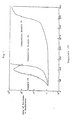
- the resulting polyetheric copolymer was placed into a melt indexer and measured for its viscosity at 400 °C in one minute and in 10 minutes. The measured viscosities were compared as follows:
- Example 2 A reactor similar to that used in Example 1 was charged with 30.962 grams (0.18 mole) of 4,4′-dichlorobenzonitrile, 75.333 grams (0.30 mole) of 4,4′-dichlorobenzophenone, 112.72 grams (0.606 mole) of 4,4′-biphenol that is somewhat larger than a total mole of the above two halides, 120.36 grams (0.72 mole) of potassium carbonate, and 3 liters of N-dimethylimidazolidinone, and the mixture was heated to 220°C over the period of 1 hour while argon is blown into the mixture.
- the product was measured for its physical properties and found to have a melt viscosity at 400°C of 16,000 poise, a glass transition temperature of 185 °C, a crystalline melting point of 378°C , and a heat decomposition temperature of 558°C .
- the resulting polyetheric copolymer was placed into a melt indexer and measured for its viscosity at 400°C in one minute and in 10 minutes. The measured viscosities were compared as follows:
- a 3-liter reactor equipped with a stirrer and a tube for introducing argon was charged with 133.09 grams (0.530 mole) of 4,4′-dichlorobenzophenone, 38.7 grams (0.225 mole) of 2,6-dichlorobenzonitrile, 140.59 grams (0.755 mole) of 4,4′-biphenol, 108.84 grams (0.79 mole) of potassium carbonate and 1,000 grams of diphenylsulfone as a solvent, and the reactor was heated from room temperature to 180 °C over the period of 1 hour and the reaction was continued at that temperature for hour. Then the mixture was raised to 270 °C over the period of 30 minutes and then continued to react at that temperature for 1 hour. The mixture was further raised to 320 °C over the period of 30 minutes and it was reacted at 320°C for another 1 hour.
- the reaction mixture was poured into a stainless vat and allowed to cool and solidify, thereby producing a film.
- the film was crushed with a blender (product of Warning) into pieces which in turn were treated with 1 liter of acetone to thereby extract and remove the diphenylsulfone used as a solvent. Then they were washed with a large amount of water to remove inorganic salts and dried, yielding 250.4 grams (yield: 98%) of the product in a white powdery form.
- the product was measured for its physical properties and found to have a melt viscosity at 400°C of 18,000 poise, a glass transition temperature of 185 °C, a crystalline melting point of 350°C , and a heat decomposition temperature of 560°C .
- the resulting polyetheric copolymer was placed into a melt indexer and measured for its viscosity at 400 °C in one minute and in 10 minutes. The measured viscosities were compared as follows:
- the polyetheric copolymer fibers as the feature (8) of the present invention is characterized that the fibers consists of the polyetheric copolymer which in turn is drawn at a draw ratio of 1.5 times or more and, more specifically, which is spun and then drawn at the draw ratio of 1.5 times or more at a temperature which is higher by 10 °C to 30 °C than its glass transition temperature.
- polyetheric resin required for the preparation of the polyetheric copolymer fibers may be conveniently used the polyetheric copolymers as have been described hereinabove in the features (1), (3) and (5) of the present invention.
- the polyetheric copolymer is particularly appropriate, which has a molar ratio of the recurring unit as represented by the general formula (I) above to a sum of the recurring units (I) and (II) ranging from 0.15:1 to 0.40:1 and a melt viscosity at 400 °C in the range from 500 ⁇ 100,000 poise, preferably from 3,000 to 50,000 poise.
- the polyetheric copolymer has a melt viscosity at 400°C ranging from 500 to 100,000 poise.
- Such a polyetheric copolymer as having a melt viscosity as low as below the lower limit may not be provided with sufficient resistance to heat and mechanical strength while a copolymer having a melt viscosity larger than the upper limit may cause a decrease in spinning performance.
- the polyetheric copolymer fibers are prepared by drawing the polyetheric copolymer at the draw ratio of 1.5 times or larger. If the copolymer is drawn by lower than the lower limit, a sufficient tensile strength cannot be achieved so that the effect of drawing is rendered insufficient.
- the polyetheric copolymer fibers prepared in the way as have been described hereinabove can exhibit a sufficient degree of a heat resistance and a favorable mechanical strength so that they may be appropriately used in various fields which require a high resistance to heat. They are further advantageous because of readiness of the preparation.
- the polyetheric copolymer fibers having such excellent characteristics as have been described hereinabove may be efficiently prepared by the processes as will be described in more detail hereinafter.
- the polyetheric copolymer may be appropriately spun by per se known melt extrusion.
- a temperature at which the copolymer is spun is higher than its melting point usually by 10 °C to 70°C , preferably by 20°C to 50°C . If the spinning temperature would be so close to its melting point as low as less than 10 °C , an amount of the copolymer to be discharged from a spinneret becomes so small that a size of filaments cannot be adjusted to a sufficient extent. If the copolymer would be spun at a temperature that is higher by more than 70°C than its melting point, a quality of the resulting spun filaments may be impaired.
- a cooling solution bath is disposed immediately under the spinneret where the resulting filaments are allowed to cool rapidly and solidify and then the filaments are wound by a torque winder or the like.
- spun filaments having smaller than 1,000 denier on the other, it is not necessarily required to provide a cooling solution bath and the spun filaments may be conveniently allowed to cool in air.
- a spinning device, a winding device and so on to be used for this spinning are not restricted to particular one and those which are conventionally used for this purpose may be conveniently applicable.
- the polyetheric copolymer thus spun in the way as have been described hereinabove is then drawn in such a way as will be described in more detail hereinafter.
- the drawing devices may include, for example, a non-contact drawing device using a heated steam, a heating medium, an electric heater or the like, a heating, multistage drawing device with contact-type heaters mounted at multiple stages, and so on.
- a temperature for drawing is higher by 10°C to 30°C than the glass transition temperature of the polyetheric copolymer to be used as a material. If the drawing temperature would be lower merely by less than 10 °C than the glass transition temperature thereof, on the one hand, the drawing performance may be impaired and no sufficient effect to be anticipated by drawing may be attained. If the drawing temperature is higher by more than 30 °C than the glass transition temperature thereof, fuzz or wrap may be caused to occur during drawing leading to an unstable drawing.
- the polyetheric copolymer is spun and drawn in the way as have been described hereinabove and then heat-treated, as desired, as will be described hereinafter.
- the heat treatment to be carried out as desired may be conducted at a temperature in a range of temperatures which are higher than a crystallization temperature of the polyetheric copolymer and which are lower than its melting point.
- the heat treatment may further improve a strength of the resulting polyetheric copolymer fibers.
- the heat treatment of the drawn filaments may be carried out under tension or without tension.
- this process can easily and efficiently provide the polyetheric copolymer fibers which can be appropriately used in various fields which require an excellent resistance to heat and mechanical stress, particularly high heat resistance.
- the polyetheric copolymer prepared in substantially the same manner as in Example 1 was molten at 400 °C and spun through a nozzle having an inner diameter of 1.0 mm, a length of 1.0 mm, and a nozzle temperature of 390 °C. Immediately after having been spun, the filaments were passed through a 30cm long tube heated at 300°C and then allowed to cool in air, thereafter winding undrawn filaments of 35 denier at a velocity of 120 meters per minute.
- the resulting undrawn filaments were then drawn at the draw ratio of two times by means of drawing rolls at the temperature of 200°C and then heat-treated at 240 °C with a heater plate, yielding polyetheric copolymer fibers.
- the polyetheric copolymer fibers thus prepared were measured for their tensile strength, elongation, knot strength and Young's modulus. The results are shown in Table 6 below.
- Example 19 The procedures of Example 19 were followed in substantially the same manner with the exception that the draw ratio is changed from two times to three times.
- the resulting polyetheric copolymer fibers were measured for their physical properties. The results are shown in Table 6 below.
- Example 19 The procedures of Example 19 were followed in substantially the same manner with the exception that the draw ratio is changed from two times to four times.
- the resulting polyetheric copolymer fibers were measured for their physical properties. The results are shown in Table 6 below.
- the polyetheric copolymer fibers as used in Example 19 was molten at 400°C and then spun through a spinneret pierced with 60 holes, each having an inner diameter of 0.45 mm and a length of 1.35 mm.
- the temperature of the spinneret was set at 390°C .
- At an exit of the spinneret was disposed a 300mm long heating tube heated at the temperature of 300°C .
- the spun filaments were passed through the heating tube, allowed to cool in air, and wound at the velocity of 150 meters per minute, thereby yielding undrawn filaments of 800 denier per 60 filaments.
- the undrawn filaments were drawn at the draw ratio of two times and heat-treated in substantially the same manner as in Example 19, resulting in the polyetheric copolymer fibers.
- Example 22 The procedures of Example 22 were followed in substantially the same manner with the exception that the draw ratio is changed from two times to three times.
- Example 22 The procedures of Example 22 were followed in substantially the same manner with the exception that the draw ratio is changed from two times to four times.
- Example 1 The procedures of Example 1 were followed in substantially the same manner with the exception that a molar ratio of 2,6-dichlorobenzonitrile to 4,4′-difluorobenzophenone was changed to 3 to 7 from 2.5 to 7.5, yielding a polyetheric copolymer having a molar ratio of the recurring unit (I) to a sum of the recurring units (I) and (II) of 0.30 to 1.
- This copolymer was measured for its physical properties resulting in a melt viscosity at 400 °C of 16,000 poise, a glass transition temperature of 185°C , a crystalline melting point of 348°C , and a heat decomposition temperature of 560°C .
- the polyetheric copolymer thus prepared in item (a) above was then spun and drawn at the draw ratio of two times in substantially the same manner as in Example 19, thus yielding drawn fibers.
- Example 25 The procedures of Example 25 were followed in substantially the same manner with the exception that the draw ratio is changed from two times to three times.
- Example 25 The procedures of Example 25 were followed in substantially the same manner with the exception that the draw ratio is changed from two times to four times.
- Example 25 The polyetheric copolymer as prepared in Example 25 was treated in substantially the same manner as in Examples 22 to 24, respectively, resulting to polyetheric copolymer fibers.
- the polyetheric copolymer fibers prepared in the manner hereinabove in the feature (8) of the present invention characterized by drawing the polyetheric copolymer having the particular recurring unit in the particular range of the molar ratio and by the particular range of the melt viscosity at the draw ratio of 1.5 times or greater are excellent in a heat resistance and mechanical strength. Furthermore, no gellation occurs in the copolymer so that the polyetheric copolymer fibers may be prepared in a ready manner.
- the polyetheric copolymer fibers may be appropriately used in various fields which require a particularly high resistance to heat.
- the heat-resistant and fire-retardant paper is characterized by papermaking the polyetheric copolymer fibers.
- the polyetheric copolymer fibers may be prepared into heat-resistant and fire-retardant paper by means of the following papermaking operation.
- the polyetheric copolymer fibers may be papermade by a wet method or by a dry method as they are as long fibers or after cut into short fibers.
- the wet method is a method equivalent of papermaking a pulp as a raw material into paper while the dry method is of an adhesive type, of a fiber bonding type, of a physical bonding type, or the like, and may be appropriately chosen depending upon usage.
- the dry method is one of preferred modes, in which the papermade paper is pressed with a press machine and contact-bonded at a temperature which is somewhat higher than a glass transition temperature of the polyetheric copolymer used as a raw material.
- the polyetheric copolymer prepared in substantially the same manner as in Example 1 was molten at 380 °C and spun into filaments using a spinneret pierced with 60 holes having an inner diameter of 0.45 mm. The filaments are wound at the velocity of 150 meters per minute.
- the resulting undrawn filaments were then drawn at the draw ratio of five times using a drawing machine of a hot plate type.
- the drawn filaments were then made into paper so as to be used by 50 grams of the drawn filaments in a 1 m2 of paper. A fiber concentration at this time was 1% by weight. A surfactant ("T260"; Matsushita Yushi K.K.) was used. The papermade paper was dried and then pressed at 200 °C. The resulting fire-retardant paper was measured for its physical properties and they were found to be as follows: Tensile strength: 4.3 kg/cm2 Tensile elongation: 2% Critical oxygen index: 40 Moisture absorption percentage: 1.2% [measured at 20°C and 65% Room Humidity (RH)].
- the polyetheric copolymer was prepared in substantially the same manner as in Example 4 and drawn in substantially the same manner as in Example 31, thereby leading to undrawn filaments of the polyetheric copolymer.
- the drawn filaments were then made into paper in substantially the same manner as in Example 31.
- the resulting fire-retardant paper was measured for its properties and they were found to be as follows: Tensile strength: 4.5 kg/cm2 Tensile elongation: 2% Critical oxygen index: 42 Moisture absorption percentage: 1.1% [measured at 20°C and 65% RH].
- the paper prepared from the polyetheric copolymer is a heat-resistant, fire-retardant paper prepared from fibers of the novel polyetheric copolymer which is provided with the particular recurring unit in the particular range of the molar ratio and the particular melt viscosity, which possesses a sufficiently high degree of molecular weight, crystallizability and resistance to heat, and which is useful as a material to be utilized, for example, in electrical, electronic equipment, and mechanical fields. Furthermore, this heat-resistant, fire-retardant paper is extremely low in moisture absorption, compared with conventional heat-resistant, fire-retardant paper, so that it can be appropriately used in electrical and electronic fields as well as in aeroplane material field, etc.
- the polyetheric copolymer films are characterized in that the polyetheric copolymer is molded into films at a temperature which is higher by 10 °C to 100 °C than its crystalline melting point.
- polyetheric resins necessary for the preparation of the polyetheric copolymer films there may be appropriately used those polyetheric copolymers prepared in the features (1), (3) and (5) of the present invention. Particularly preferred are those polyetheric copolymers which further possess a melt viscosity at 400 °C ranging from 3,000 to 100,000 poise.
- the polyetheric copolymer films may be prepared by forming the polyetheric copolymer into films.
- Formation into films may be carried out by extruding the polyetheric copolymer by means of conventional method such as press molding method, extrusion molding method or the like at a temperature higher by from 10°C to 100°C , preferably from 20°C to 70°C , than a crystalline melting point of the polyetheric copolymer and by cooling the extruded films rapidly, thereby leading to highly-transparent, amorphous films.
- conventional method such as press molding method, extrusion molding method or the like at a temperature higher by from 10°C to 100°C , preferably from 20°C to 70°C , than a crystalline melting point of the polyetheric copolymer and by cooling the extruded films rapidly, thereby leading to highly-transparent, amorphous films.
- Formation of drawn films may be conducted by drawing, stretching or orienting uniaxially or biaxially at a temperature ranging from a glass transition temperature of the polyetheric copolymer to its crystalline melting point.
- the drawn films can be heat-treated, as needed, under tension or without tension, at a temperature which is higher than its crystalization temperature (a temperature at which the copolymer in an amorphous state is crystallized during heat treatment (while the temperature is being elevated) while the film is being forming) yet lower than its crystalline melting point.
- a temperature which is higher than its crystalization temperature a temperature at which the copolymer in an amorphous state is crystallized during heat treatment (while the temperature is being elevated) while the film is being forming
- the polyetheric copolymer films may be drawn, stretched or oriented preferably at the draw ratio in the range from 1.5 times to 10 times, more preferably by from 2 times to 5 times, by means of the methods as have been described hereinabove.
- polyetheric copolymer films as prepared in the manner as have been described hereinabove may be used for extensively broad industrial usage in an approximately whole area of electronics and electrical insulation fields.
- the polyetheric copolymer prepared in Example 1 was pressed at 400°C into a film which, in turn, was placed into water and allowed to cool rapidly, thereby yielding a transparent, amorphous film having a thickness of 200 ⁇ m.
- the film was then measured for its properties and found to have a tensile strength of 9 kg/mm2, a tensile modulus of 210 kg/mm2, a breaking extension of 210% (as measured in each of the above cases in accordance with ASTM D882), and an critical oxygen index of 31.5 (as measured in accordance with ASTM D2863).
- the polyetheric copolymer prepared in Example 1 was pressed at 400°C into a film which, in turn, was placed into water with ice cubes, thereby producing a transparent, amorphous film having a thickness of 200 ⁇ m. The film was then heat-treated at 250°C for 1 minute yielding a crystallized film.
- the resulting crystallized film was found to have a tensile strength of 11 kg/mm2, a tensile modulus of 250 kg/mm2, and a breaking extension of 130%. It was also measured for its critical oxygen index which was found to be excellent in fire-retardancy as high as 31.5.
- the crystallized film was further measured for its resistance to solvents. Although it has swelled to some extent in concentrated sulfuric acid when immersed for a long period of time, it has been found to be stable against a strong acid such as hydrochloric acid, nitric acid and trifluoroacetic acid, a strong alkali such as sodium hydroxide or potassium hydroxide, an organic solvent such as acetone, dimethylether, methylethyl ketone, benzene, toluene, ethyl acetate, dimethylformamide, N-methylpyrrolidone and methylene chloride, and hot water.
- a strong acid such as hydrochloric acid, nitric acid and trifluoroacetic acid
- a strong alkali such as sodium hydroxide or potassium hydroxide
- an organic solvent such as acetone, dimethylether, methylethyl ketone, benzene, toluene, ethyl a
- a film was prepared in substantially the same manner as in Example 33 using polyether ether ketone ("Victrex PEEK 450G"; ICI, Ltd.) and measured for its physical properties in the same manner as hereinabove.
- the resulting film was dissolved in p-chlorophenol, dichloroacetic acid and so on as well as in concentrated sulfuric acid. It has caused crazing to some extent when immersed in acetone.
- the polyetheric copolymer prepared in Example 1 was pressed at 400°C into a film which, in turn, was placed into water with ice cubes, thereby producing a transparent, amorphous film having a thickness of 200 ⁇ m.
- the film was then withdrawn at the drawing velocity of 1,000% per minute under conditions as will be described in Table 7 below using a uniaxial drawing machine (Shibata Kikai K.K.) or a biaxial drawing machine (Toyo Seiki Seisakusho K.K.).
- An amorphous film was prepared in substantially the same manner as in Example 33, in which the polyetheric copolymer prepared in Example 4 was used in Example 36, the polyetheric copolymer prepared in Example 5 was used in Example 37, and the polyetheric copolymer prepared in Example 1 except changing its molar ratio of the recurring unit (I) to a sum of the recurring units (I) and (II) to 0.40:1 was used in Exanple 38.
- the drawn film was then prepared from the undrawn film under drawing and heat fixing conditions as shown in Table 7 below.
- Example 35 Using the polyetheric copolymer prepared in Example 4, the procedures of Example 35 were followed in substantially the same manner except using different draw ratio and heat fixing conditions, as shown in Table 7 below, thereby forming a drawn film.
- the polyetheric copolymer films according to the present invention possess favorable moldability as well as excellent mechanical strength, heat resistance, fire-retardancy and resistance to solvents because they use the polyetheric copolymers having a high glass transition temperature and containing no gelled ingredient as a raw material.
- Polyetheric copolymer pipes according to the feature (11) of the present invention is characterized in that they are molded from the polyetheric copolymers according to the present invention.
- polyetheric copolymers for the preparation of these pipes there may be appropriately used those as prepared in the features (1), (3) and (5) of the present invention.
- the polyetheric copolymer pipes may be prepared in per se known molding method using the polyetheric copolymers as have been described hereinabove.
- the molding method to be applied to the process for the preparation of the pipes according to the present invention may include, for example, extrusion molding method, injection molding method, transfer molding method and so on.
- the polyetheric copolymer may be molten and extruded from a die by a usual extrusion molding machine, sized and then allowed to cool.
- the die may be of a straight head type, of a cross head type or of an offset type.
- Sizing may be implemented by any method including, for example, a sizing plate method, an outside mandrel method, an inside mandrel method, and a sizing box method.
- Fitting of pipes may be appropriately implemented by means of injection molding.
- a composition in admixture of the polyetheric copolymer with an additive such as a filler, glass fibers, carbon fibers, fiber reinforcing material or the like may be used as a raw material for pipes as long as the additive is added in an amount which does not impair the object of the present invention.
- the resin pipes prepared by molding the polyetheric copolymer predominantly have characteristics as will be described hereinafter.
- the resin pipes according to the present invention have mechanical properties such as high tensile strength and bending strength, sufficiently large impact strength, as well as excellent surface hardness and resistance to wear so that they may be applied under severe conditions in a stable manner.
- the resin pipes have thermal properties such as high glass transition temperature, heat distortion temperature, and heat decomposition temperature so that they can maintain their properties to a sufficient extent under circumstances where the temperature is as high as above 200 °C . They are further provided with a sufficient degree of fire-retardancy.
- the resin pipes have chemical properties such that they are extremely stable chemically against a strong acid except concentrated sulfuric acid, a strong alkali, and an organic solvent without being corrosive.
- the polyetheric copolymer was prepared in substantially the same manner in Example 1 with the exeption that a scale was increased to ten times.
- the resulting polyetheric copolymer was found to have the same tensile strength, tensile modulus, tensile elongation, bending strength, bending modulus, Izod impact strength (notched), and heat distortion temperature as shown in Table 1 above. It was further found to have a Rockwell hardness (M scale) of 96 and a coefficient of dynamic friction ( ⁇ ) of 0.19. It is to be noted herein that the Rockwell hardness was measured in accordance with ASTM D-785 and that the coefficient of dynamic friction was measured with a velocity of 0.6 meter per second and a load of 20 kg per cm2 using S45C as a partner material.
- the polyetheric copolymer was molded by extrusion molding at the cylinder temperature of 380°C into a pipe having an outer diameter of 32 mm and a thickness of 3 mm.
- the pipe was cut to 5 cm and washed in order with trichloroethylene, methanol and purified water and then immersed in purified water at 23°C or in purified water at 60°C .
- the pipes were then allowed to stand for 7 days and an amount of total organic carbons eluted in the purified water in which the pipes had been immersed was measured with a total organic carbon tester (Model: TOC-720; Toray Engineering Co., Ltd.).
- the amounts of the total organic carbons were 1.4 ppm in the purified water at 23 °C and 2.6 ppm in the purified water heated at 60 °C .
- Test pieces cut from the pipe prepared hereinabove were measured for their solubility in solvents and found to be insoluble in acetone, chloroform, carbon tetrachloride, methylene chloride, ethanol, toluene and xylene.
- test pipe pieces were measured for their resistance to chemicals and found that they are swelled to some extent in concentrated sulfuric acid yet they are thoroughly safe against hydrochloric acid, nitric acid and sodium hydroxide.
- test pipe pieces were measured for a critical oxygen index and found to be as high as 41.
- the polyetheric copolymer was prepared in substantially the sane manner as in Example 4 above on an increased scale.
- the resulting polyetheric copolymer was found to have the same physical properties as that used in Example 4.
- the physical properties of the polyetheric copolymer are as follows: Tensile strength: 1,050 kg/cm2 Tensile modulus: 32,000 kg/cm2 Tensile elongation: 67% Bending strength: 1,960 kg/cm2 Bending modulus: 36,300 kg/cm2 Izod impact strength (notched): 13.6 kg ⁇ cm/cm Rockwell hardness (M scale): 95 Coefficient of dynamic friction: 0.21 ⁇ Heat distortion temperature: 207 °C
- the resulting polyetheric copolymer was molded into a pipe having an outer diameter of 32 mm and a thickness of 3 mm in the same manner as in Example 41.
- the pipe was also measured for its amount of organic substances eluted, resistance to hot water, solvents and chemicals, and fire-retardancy in the same manner as in Example 41.
- a pipe was molded using polyether ether ketone ("Victrex PEEK 450G”; ICI, Ltd.) as a starting resin.
- the pipe was measured in the same manner as in Example 41 for an amount of organic carbons eluted in purified water.
- the amount of the organic carbons eluted was 3.0 ppm in the purified water at 23 °C and 5.5 ppm in the water at 60°C .
- the pipe was also immersed in purified water at 180 °C for seven days and found that no distortion on its appearance was caused to occur.
- a hard vinyl chloride resin pipe having an outer diameter of 32 mm and a thickness of 3 mm was measured for its amount of organic carbons eluted in purified water.
- the amount of the organic carbons eluted was 3.2 ppm in the purified water at 23°C and 15.2 ppm in the purified water at 60°C .
- the pipe was further measured for a distortion of its appearance by immersing it in purified water at 180 °C for seven days. As a result, no distortion on its appearance was found.
- the polyetheric copolymers according to the present invention are a favorable material having excellent mechanical strength, heat resistance, and chemical resistance
- the pipes resulting from the copolymers are suitable for a wide variety of usage because of a pressure-resistant strength, a wear resistance, and durability as well as an elution of a small amount of organic substances.
- Electrical insulating materials as the feature (12) of the present invention is characterized in that they are molded from the polyetheric copolymers according to the present invention.
- polyetheric copolymers for the preparation of the electrical insulating materials the above mentioned polyetheric copolymers of (1), (3) and (5) are usually used.
- the polyetheric copolymers to be used in accordance with the present invention have, for example, a crystalline melting point of 330°C to 400 °C, crystallizability, a sufficiently high molecular weight, a sufficient heat resistance, an excellent resistance to solvents and mechanical stress. It is also found to have a volume specific resistance as high as polyether sulfones yet larger than polyether ether ketones. A dielectric constant of the polyetheric polymer was found to be as approximately high as polyether ether ketones yet lower than polyether sulfones. Furthermore, the polyetheric copolymer according to the present invention was found to have a dielectric dissipation factor as high as the polyether ether ketones and polyether sulfones as well as to be superior in high-frequency characteristics to them.
- the polyetheric copolymers according to the present invention have superior physical properties, such as heat resistance, fire-retardancy, chemical resistance, and mechanical strength, so that they can be used under severe conditions and utilized as electrical insulating materials to be applicable to a wide variety of fields.
- the polyetheric copolymers can be appropriately used, for example for telecommunication instrument, electronic instrument, industrial instrumentation and other usual instrument.
- They may be used, for example, by providing wires with coatings by means of extrusion molding, by coating the copolymer in a molten state or by bonding the copolymer in a film form.
- the polyetheric copolymer was prepared in substantially the same manner as in Example 1 and injection-molded to test pieces which were then measured for their electrical properties. The test results are shown in Table 8 below.
- polyetheric copolymer was found to have the same tensile strength, tensile modulus, elongation, bending strength and bending modulus as those shown in Table 1 above.
- Example 44 the polyetheric copolymer prepared in Example 6 was measured for its mechanical strength and fire-retardancy; in Example 45, the polyetheric copolymer prepared in Example 5 was measured therefor; and in Example 46, the polyetheric copolymer prepared in Example 38 was measured therefor.
- the polyetheric copolymers according to the present invention are high in heat distortion temperature and resitance to heat as well as excellent in fire-retardancy, resistance to chemicals and mechanical strength so that they are suitable for electrical insulating materials.
- the flexible printed circuit boards according to the present invention are characterized by electrical insulating substrate composed of the polyetheric copolymer in the flexible printed circuit boards having an electrical conductive layer on a surface of the insulating substrate.
- polyetheric copolymer to be used for the insulating substrate there may be used those described hereinabove in the features (1), (3) and (5) of the present invention. Particularly preferred are the polyetheric copolymers having a molar ratio of the recurring unit as represented by the general formula (I) above in the range from 0.15:1 to 0.40:1, preferably from 0.20:1 to 0.30:1, and a melt viscosity at 400 °C in the range of 500 to 100,000 poise.
- the insulating substrate can be used the polyetheric copolymer film as have been described hereinabove in the feature (9) of the present invention.
- the polyetheric copolymer film is excellent in mechanical strength and electrical properties and has a coefficient of linear expansion as small as copper, that is an important property for the preparation of flexible printed circuit boards. It also is so small in a water absorption ratio, a moisture absorption ratio and a coefficient of humidity expansion that it has a small dimensional change and a good adhesion to the conductive layer laminated on tne substrate.
- the conductive layer disposed on a surface of the insulating substrate may be formed by a metal foil obtained by electrolyzing or rolling of a metal selected from copper, aluminium, nickel and silver.
- a film thickness of the conductive layer may range usually from 5 to 500 ⁇ m, preferably from 10 to 100 ⁇ m. In the case of a copper foil obtained by rolling, its film thickness may range preferably from 15 to 50 ⁇ m, and in the case of a copper foil obtained by electrodeposition, its film thickness may preferably from 10 to 50 ⁇ m.
- an adhesive may be coated on a surface of the insulating substrate or an adhesive film is sandwiched and then compressed at a temperature ranging usually from 50 °C to 200 °C, preferably from 100 °C to 150 °C, under a pressure ranging usually from 0.1 to 10 kg/cm2, preferably from 1 to 5 kg/cm2.
- the conductive layer may be formed on the surface of the insulating substrate by means of non-electrolytic deposition method, metallizing method, vaporization method, sputtering method or the like.
- the conductive layer may be formed on one surface or two surfaces of the insulating substrate.
- the flexible printed circuit boards as have been prepared hereinabove may be formed with a conductive pattern by means of substractive (photo-etching) method or additive method and thereafter holes are bored with drills, through which electronic devices are soldered.
- the flexible printed circuit boards thus prepared may be used for industrial electronic equipment such as electronic computers, electronic switching system, office automation equipment, wire communication devices, wireless communication devices, electronic application instruments, electrical instrumentation devices and so on, and public electronic equipment such as radios, television sets, tape recorders, audio instruments, video tape recorders, and so on.
- the folowing is directed to an example and a comparative example relating to the flexible printed circuit boards as the feature (13) of the present invention.
- the polyetheric copolymer was prepared in the same manner as in Example 1 and press-molded at 400°C into a film which in turn was subjected to heat treatment at 250°C for 1 minute, thereby resulting in a crystalline film having a thickness of 25 ⁇ m.
- the resulting printed circuit board was measured for its properties as follows: Coefficient of linear expansion (ASTM D-969-44): 2.1 x 10 ⁇ 5 cm/cm/ °C Moisture absorption ratio (ASTM D-570-63): 50% RH: 0.04% Immersion for 24 hours: 0.12% Coefficient of humidity expansion (22.2 °C ; 20-80%RH): 1.8 x 10 ⁇ 7 cm/cm/%RH Dielectric constant (ASTM D-156): 1 KH z : 3.2 Dielectric dissipation factor (ASTM D-150): 1MH z : 0.0035
- a printed circuit board was prepared in the same manner as in Example 47 With the excepttion that an aromatic polyimide ("KAPTON”; DuPont) in a film form having a thickness of 25 ⁇ m.
- KAPTON aromatic polyimide
- the resulting printed circuit board was measured for its properties as follows: Coefficient of linear expansion (ASTM D-969-44): 2.0 x 10 ⁇ 5 cm/cm/ °C Moisture absorption ratio (ASTM D-570-63): 50% RH: 1.3% Immersion for 24 hours: 2.9% Coefficient of humidity expansion (22.2 °C ; 20-80%RH): 2.2 x 10 ⁇ 5 cm/cm/%RH
- the followng is a description on radiation-resistant materials as the feature (14) of the present invention.
- the radiation-resistant material is characterized in using the polyetheric copolymer of the present invention as a material.
- the polyetheric copolymer is so favorable in radiation resistance that it can be used as a material for sheet materials, sealing materials, frame materials, hoses, packing materials and so on to be used for instrument, devices, and apparatuses, such as, for example, nuclear reactors, breeders, ionized radioactivity generators or the like.
- the following is directed to an example and comparative examples relating to radiation-resistant materials.
- the polyetheric copolymer was prepared in substantially the same manner as in Example 1.
- the resulting polyetheric copolymer was extruded at 400 °C with a twin-screw extruder and pelletized.
- the pellets were extruded from a T-die into a film having a width of 25 cm and a thickness of 100 ⁇ m.
- the film was then irradiated with electron rays of 21 Mega Gray (Mgy) per hour in an irradiation amount as shown in Table 10 below and then measured for its tensile strength in accordance with ASTM D882.
- the polyetheric copolymer according to the present invention is so excellent in a resistance to radiation that it is useful as a radiation-resistant molding material to be used for instrument which is exposed to radiation.
- the powder paints according to the present invention are characterized in using the polyetheric copolymers of the present invention as a material.
- the polyetheric copolymers prepared by the processes as in the features (2-1), (2-2), (2-3), (4) and (6) above may be used for the preparation of the powder paints according to the present invention
- the polyetheric copolymers prepared by the process as have been described hereinabove in the feature (7) of the present invention are provided in a form of powders having particle sizes in the range from 1 ⁇ m to 200 ⁇ m so that they are appropriately used for the powder paints of the present invention. Thus they may be conveniently used as they are or in admixture with an appropriate pigment.
- the polyetheric copolymers according to the present invention may be used as powder paints as they are, the powder paints may contain pigments, other resins, fillers or the like, as needed.
- ceramic-type heat-resistant color pigments there may be preferably used ceramic-type heat-resistant color pigments.
- Such pigments may include, for example, alumina, silica, beryllia, zirconia, magnesia, titanium oxide, iron oxide, barium titanate, calcium titanate, lead titanate, zircon, barium zirconate, steatite, talc, clay, montmorillonite, bentonite, kaolin, mica, boron nitride, silicon nitride or the like.
- These pigments may function as colorants of the paints and improve a smoothness on coatings as well. They may be used singly or in combination of two or more pigments. In either case, it is desired that these pigments have an average particle size of 200 mesh or smaller.
- the other resins to be used with the polyetheric copolymer may include, for example, a silicone resin, an epoxy resin, an alkyd resin, a phenol resin, a melamine resin and so on. They may be used singly or in combination with two or more.
- the fillers to be used with the polyetheric copolymer may include, for example, fine powders of a high melting-point inorganic filler, low melting-point glass, and so on.
- the amount of the polyetheric copolymer may be preferably in the range of 50% by weight or larger.
- the paints containing powders of the polyetheric copolymer may be coated by fluidization dip coating, spraying, electrostatic powder spraying, electrostatic fluidization dip coating, flame spray coating or the like.
- the coat may be baked at temperatures ranging from 400 °C to 520 °C , preferably from 420 to 480 °C .
- the polyetheric copolymer was prepared in substantially the same manner as in Example 1 and coated by means of fluidization dip coating in a manner as will be described hereinafter.
- the undercoated plate was then overcoated at 420°C with the polyetheric copolymer, thus forming an overcoat having a film thickness of 100 ⁇ m on the plate.
- the overcoated plate was measured for its solubility in solvents. As a result, it was found to be insoluble in trichloroethane, acetone, carbon tetrachloride, chloroform, benzene, toluene, xylene and ethanol.
- the coat was further measured for its surface hardness according to the pencil hardness test according to JIS K5400. As a consequence, the pencil hardness of the overcoat was found to be HB.
- a heat resistance of the overcoat was measured by placing the overcoated plate in an oven at 340°C for one week. As a result, neither discoloration nor cracks were recognized.
- the overcoat was further measured for its weathering properties using a sunshine weather meter by exposure for 800 hours. It was found as a result that neither discoloration nor cracks were observed.
- Example 49 Using powders of the polyetheric copolymer prepared in substantially the same manner as in Example 4, a coat was formed in a film thickness of 120 ⁇ m in substantially the same manner as in Example 49.
- the resulting coat was measured for its resistance to solvents and chemicals, surface hardness, heat resistance and weathering properties in a manner similar to those measured in Example 49 and it was found to have the same physical properties as the coat prepared in Example 49.
- the powder paints prepared from the polyetheric copolymers according to the present invention can provide a coat which is excellent in resitance to heat and chemicals as well as weathering properties.
- powder paints according to the present invention can give the effect of causing no risk of explosion because of the excellent fire-retardancy of the polyetheric copolymers as have been described hereinabove.
- the polymers prepared by the paticular polymerization process can be isolated in a form of powders from the reaction mixture, they can be used in a coating system as the powder paints as they are.
- the inorganic compounds coated with the polyetheric copolymer according to the present invention is characterized in that the inorganic compounds are coated with the polyetheric copolymer.
- the inorganic compounds to be used for the present invention may include, for example, an inorganic filler, an inorganic reinforcing agent, an inorganic fire-retardant agent, an inorganic colorant and so on.
- a material of such inorganic compounds may be enumerated a metal such as iron, copper, zinc, lead, bismuth, nickel, chromium, tungsten, molybdenum, cobalt, aluminium, magnesium, titanium, beryllium, silicon, lithium, potassium, gold, silver, platinum, gallium, indium, tellurium, lanthanum and cerium; an alloy such as nickel steel, chromium steel, tungsten steel, molybdenum steel and titanium alloy; a metal oxide such as antimony trioxide, iron oxide, titanium oxide, alumina, silica and zirconia; a metal hydroxide such as aluminium hydroxide, zirconium hydroxide, magnesium hydroxide and calcium aluminate hexahydrate;
- the inorganic compounds to be used may be in any form and they may be in a form of granules, plates, needles, and fibers. Among them, the inorganic compounds in the granular form are preferred and the carbonates such as calcium carbonate and the metal oxides such as titanium dioxide, each in the granular form, are particularly preferred.
- the inorganic compounds may be used singly or in combination of two or more.
- the inorganic compounds coated with the polyetheric copolymer may be prepared, for example, by reacting the dihalogeno benzonitrile with the 4,4′-biphenol in the presence of the alkali metal compound and the inorganic compound in the aprotic polar solvent and then adding the 4,4′-dihalogeno benzophenone.
- This series of reactions may be carried out at a temperature which ranges usually from 150 °C to 380 °C preferably from 180 °C to 330 °C .
- the inorganic compounds coated with the polyetheric copolymer according to the present invention may also be prepared, in addition to the above process, by simultaneously reacting the dihalogeno benzonitrile and 4,4′-dichlorobenzophenone with the 4,4′-biphenol in the presence of the alkali metal compound and the inorganic compound in the aprotic polar solvent and then by copolymerizing the resulting product with the 4,4′-difluorobenzophenone.
- the inorganic compound coated with the polyetheric copolymer may be separated and purified by a per se known process from the aprotic polar solvent containing the resulting inorganic compound coated with the copolymer.
- the inorganic compound coated with the polyetheric copolymer according to the present invention is in such a state that the polyetheric copolymer having the excellent properties such as resistance to heat, solvents and chemicals is coated on a surface of the inorganic compound.
- a film thickness of the coating may be adjusted by changing a concentration of the polyetheric copolymers in the aprotic polar solvent.
- the resulting inorganic compound coated with the polyetheric copolymer is provided with resistance to heat and to organic solvents, acids and other chemicals. Furthermore, it has an improved wetting on its surface so that dispersibility into a matrix is improved.
- the following example is directed to the inorganic compound coated with the polyetheric copolymer as the feature (16) of the present invention.
- Example 1 The procedures of Example 1 was followed except adding 11.98 grams (0.15 mole) of rutile titanium dioxide in the first step of reaction, thereby yielding titanium dioxide coated with the polyetheric copolymer.
- the resulting granular polyetheric copolymer coating was found to have the same properties as the polyetheric copolymer prepared in Example 1.
- the granular the polyetheric copolymer coating was tested for solubility in solvents and found to be insoluble in acetone, chloroform, carbon tetrachloride, methylene chloride, ethanol, toluene and xylene. It was also found that it was not corroded with acids other than concentrated sulfuric acid.
- the powders were then molten and kneaded in the amount of 20 parts by weight with respect to 100 parts by weight of polyethylene, thereby yielding a titanium dioxide-polyethylene composition.
- a sheet of the composition was observed electron-microscopically for its surface layer portion and an inner section (multiplied by 1,000 times and 3,000 times) and confirmed that the titanium dioxide particles coated with the polyetheric copolymer were dispersed homogeneously in the polyethylene and that the both were bonded tightly to each other.
- the inorganic compounds coated with the polyetheric copolymers are such that the inorganic compounds are coated with the polyetheric copolymers according to the present invention so that the resulting coatings are not corroded by organic solvents and are superior in resistance to acids and heat.
- the inorganic compounds coated with the polyetheric copolymers can provide industrially useful paints, fibers, paper and other products.
- a variation in molar ratios of the polyetheric copolymers can adjust a film thickness of coatings of the inorganic compound coated with the polyetheric copolymer, thus providing products which can be applied in various usage.
- polyetheric copolymer compositions as the feature (17) of the present invention, which includes three compositions as will be described hereinafter as polyetheric copolymer compositions (A), (B) and (C) for brevity of explanation.
- the polyetheric copolymer compositions (A) according to the present invention are characterized in blending the polyetheric copolymers of the present invention in an amount of 97% to 30% by weight with an inorganic filler in an amount of 3% to 70% by weight.
- polyetheric copolymers to be used for the preparation of the polyetheric copolymer compositions according to the present invention may be those described hereinabove as in the features (1), (3), and (5) of the present invention.
- the inorganic fillers to be used for the present invention may further include, for example, an inorganic compound such as various oxides, hydroxides, carbides, nitrides, borides, sulfides, halides, carbonates, sulfates, phosphates, silicates, aluminates, titanates, plumbates and other various compound oxides, carbon such as graphite, and a simple substance of other stable non-metals, stable metals or semi-metals or granular particles of a mixture or a compound substance thereof.
- an inorganic compound such as various oxides, hydroxides, carbides, nitrides, borides, sulfides, halides, carbonates, sulfates, phosphates, silicates, aluminates, titanates, plumbates and other various compound oxides, carbon such as graphite, and a simple substance of other stable non-metals, stable metals or semi-metals or granular particles of a mixture or a
- the inorganic particles or the inorganic compounds or the simple substances to be used as a component thereof may include, for example, alumina, indium oxide, silica, germanium oxide, lead oxide, tin oxide, beryllia magnesia, zinc oxide, yttria, lanthanum oxide, zirconia, tita-nium oxide, tantalum oxide, molybdenum oxide, tungsten oxide, manganese oxide, iron oxide, barium titanate, calcium titanate, lead titanate, zircon, barium zirconate, steatite, talc, clay, montmorillonite, bentonite, kaolin, mica, boron nitride, diato-maceous earth, zeolite, silica alumina, silica magnesia, silica titania, silicon carbide, silicon nitride, titanium nitride, sodium chloride, iron chloride, calcium carbo-nate, magnesium carbonate, magnesium
- the inorganic fillers may be in any form, such as granules, plates or fibers. Particularly, the inorganic fillers in a form of fibers can improve a modulus of elasticity of the resulting polyetheric copolymer composition to a remarkably large extent.
- the fibrous inorganic fillers may include, for example, carbon fibers, glass fibers, alumina fibers, SiC fibers, boron fibers, aramide fibers, metal fibers, aromatic polyamide fibers, and various whisker fibers. Among those fibers, carbon fibers and glass fibers are preferred.
- the carbon fibers are not restricted to a particular one and may include, for example, polyacrylonitrile (PAN) type carbon fibers, cellulose type carbon fibers, pitch type carbon fibers, vapor phase growth carbon fibers, dehydrated polyvinyl alcohol (PVA) type carbon fibers and so on.
- PAN polyacrylonitrile
- cellulose type carbon fibers cellulose type carbon fibers
- pitch type carbon fibers cellulose type carbon fibers
- vapor phase growth carbon fibers vapor phase growth carbon fibers
- PVA dehydrated polyvinyl alcohol
- the glass fibers are also not restricted to a particular one and may be those prepared by the direct melting method or by the Marble method.
- Particle sizes of the inorganic fillers may be in the range generally from 20 ⁇ m or smaller.
- sizes of the fibers are not restricted to particular ones and may be in the range usually from 5 to 20 ⁇ m, preferably from 7 to 15 ⁇ m.
- An aspect ratio of the fibrous inorganic filler may be in the range usually from 100 to 3,000, preferably from 500 to 2,000.
- the inorganic filler is surface-treated prior to blending.
- Surface-treatment of the inorganic filler can improve its wetting performance with a thermoplastic resin composition as a matrix and, as a result, the polyetheric copolymer composition can also improve its mechanical strength and other properties.
- the inorganic fillers may be blended in an amount ranging usually from 3% to 70% by weight, preferably from 5% to 30% by weight, based on a total weight of the inorganic filler and the polyetheric copolymer. If the amount of the inorganic filler is too small, the resulting composition may not be provided with improved resistance to heat and mechanical strength. Even if the inorganic filler would be used in an amount larger than the upper limit, there cannot be achieved any further improvement in effects to be anticipated by an increase in the inorganic filler and, rather, a moldability of the resulting polyetheric copolymer composition can be impaired.
- the polyetheric copolymer compositions according to the present invention can be said to have excellent heat resistance and mechanical stress that are further improved from those possessed by the polyetheric copolymer itself.
- the polyetheric copolymer compositions according to the present invention may be prepared by blending the specified amount of the polyetheric copolymer with the specified amount of the inorganic filler and kneading them to a sufficient extent so as to disperse the inorganic filler homogeneously into the mix. Kneading is effected at a temperature which melts the polyetheric copolymer. The temperature cannot be determined in a single condition because it may vary with conditions of the polyetheric copolymer composition to be used. The temperature, however, may range usually from 300°C to 500 °C , preferably from 340 °C to 420°C . A period of time to be required for melting and kneading the polyetheric copolymer may be in the range usually from 1 to 10 minutes, preferably from 2 to 5 minutes.
- Processes of blending and kneading are not restricted to particular ones and may be a one in which the polyetheric copolymer is blended in a molten state, for example, with a kneader mixer or an extruder containing two or more screws which are rotating in the directions equal to or opposite to each other, or with a single-shaft extruder containing one screw which is moving forward and backward while being rotated, thereby resulting in a homogeneous dispersion of the inorganic filler.
- the resulting molten resin composition is then allowed to cool by appropriate means yielding the desired polyetheric copolymer composition.
- the polyetheric copolymer composition thus prepared is then formed, as needed, into pellets and other shapes which, in turn, may be molded by means of molding method such as injection molding into desired molded products.
- Examples 52 and 53 below are directed to the polyetheric copolymer compositions (A) according to the present invention.
- the polyetheric copolymer prepared in the same manner as in Example 1 and glass fibers having an average fiber diameter of 10 ⁇ m and an average fiber length of 3 mm were kneaded at 360 °C with an extruder and extruded thereform into pellets.
- the content of the glass fibers is 30 wt% in the pellets.
- the polyetheric copolymer prepared in the same manner as in Example 1 and carbon fibers having an average fiber diameter of 9 ⁇ m (“TORAYCA”; Toray, Ltd.) were kneaded at 360°C with an extruder and extruded thereform into pellets.
- Example 1 Example 52
- the polyetheric copolymer compositions (B) according to the present invention are characterized in containing 100 parts by weight of the polyetheric copolymers of the present invention and an inorganic nucleating agent in an amount equal to or larger than 0.001 parts by weight yet less than 3 parts by weight.
- the inorganic nucleating agent there may be used those enumerated for the polyetheric copolymer compositions (A) as the feature (17) of the present invention. Among them, graphite, titanium dioxide, talc, silicon carbide, mica, titanium nitride, silicon nitride and so on are preferred.
- the inorganic fillers may be used as particles consisting of a single ingredient or particles consisting of compositions containing two or more ingredients. These inorganic particles may be used, as needed, in admixture with other particles.
- Sizes of the inorganic particles to be blended as the nucleating agent may range usually from 20nm to 10 ⁇ m. If the particle sizes are too small, a sufficient improvement in a velocity of crystallization may not be achieved. If they becomes too large, a homogeneous dispersibility may be impaired so that crystallization may occur in an irregular way and a velocity of crystallization may not be improved to a sufficient extent.
- the inorganic nucleating agent may be blended with 100 parts by weight of the polyetheric copolymer in an amount equal to or larger than 0.001 part but less than 3 parts by weight.
- the amount of the inorganic nucleating agent is below the lower limit, the effect of improving the velocity of crystallization becomes insufficient, on the one hand. If the amount thereof exceeds the upper limit, no further effect can be achieved for improvements in the velocity of crystallization, on the other hand.
- polyetheric copolymer compositions (B) as the feature (18) according to the present invention may be prepared in substantially the same manner as the polyetheric copolymer compositions (A) as described in the feature (17) of the present invention.
- the polyetheric copolymer prepared in substantially the same manner as in Example 1 was blended with graphite (average particles size: 7 ⁇ m) as a nucleating agent in an amount of 1.0 part by weight with respect to 100 parts by weight of the polyetheric copolymer, molten at 380°C and kneaded for three minutes usisng a twin-screw extruder, thereby yielding a resin composition for molding.
- graphite average particles size: 7 ⁇ m
- the composition was molded into pellets as test sample, which were then measured for its crystallization temperature (Tc) with a differential scanning calorimeter (DSC).
- Tc crystallization temperature
- DSC differential scanning calorimeter
- Example 54 The procedure of Example 54 was followed in the same manner with the exception that, in place of graphile, titanium dioxide (average particles size: 0.2 ⁇ m) was used in Example 55; talc (average particles size: 0.5 ⁇ m) in Example 56; silicon carbide (average particles size: 8 ⁇ m) in Example 57; mica (average particles size: 5 ⁇ m) in Example 58; titanium nitride (average particles size: 1.5 ⁇ m) in Example 59; and silicon nitride (average particles size: 2 ⁇ m) in Example 60; and each of the inorganic nucleating agents was blended in an amount of 1.0 parts by weight based on 100 parts by weight of the polyetheric copolymer prepared in substantially the same manner as in Example 1.
- Tc The crystallization temperature (Tc) in each of the Examples above is shown in Table 12 below.
- the polyetheric copolymer prepared in substantially the same manner as in Example 1 was treated in the same manner as in Example 54, except adding no nucleating agent, thereby yielding a polyetheric copolymer composition.
- the polyetheric copolymer compositions for molding are a blend of the particular polyetheric copolymer with the nucleating agent consisting of the specified inorganic particles in the particular ratio so that it is advantageous that the velocity of crystallization is so fast that a molding cycle can be shortened during the preparation of molded products therefrom.
- the polyetheric copolymer compositions (C) according to the feature (19) of the present invention is characterized in that 10% to 90% by weight of the polyetheric copolymer is blended with 90% to 10% by weight of a heat-resistant thermoplastic resin and, as desired, with a filler in an amount ranging from 1 to 50% by weight with respect to 100% by weight of a total weight of the polyetheric copolymer and the thermoplastic resin.
- thermoplastic resins to be used therefor may include, for example, engineering plastics such as polyamide resins, polyether ether ketones, polyacetals, polycarbonate resins, thermoplastic polyester resins, polyphenylene oxides, polyether sulfones, polyimides, polyamide imides, polyether imides, polysulfones and polyphenylene sulfides.
- engineering plastics such as polyamide resins, polyether ether ketones, polyacetals, polycarbonate resins, thermoplastic polyester resins, polyphenylene oxides, polyether sulfones, polyimides, polyamide imides, polyether imides, polysulfones and polyphenylene sulfides.
- the polyamide resins may include, for example, nylon 6, nylon 8, nylon 11, nylon 66, nylon 610 and so on.
- the polyacetals may be a homopolymer or a copolymer.
- the polycarbonates may include, for example, a polycarbonate obtainable from bisphenol A and phosgene, a polycarbonate obtainable from bisphenol A and diphenyl carbonate, and so on.
- thermoplastic polyester resins may include, for example, polyethylene terephthalate, polypropylene terephthalate, polybutylene terephthalate, polyarylate, aromatic polyester, crystalline polyester and so on.
- the polyetheric copolymer compositions may be used for molding into products in various forms and shapes so that the thermoplastic resins to be blended therewith may be appropriately chosen from various thermoplastic resins as long as they possess molecular weights in which they can be molded.
- thermoplastic resins may be used singly or in combination with two or more as a polymer blend.
- thermoplastic resins among those enumerated are polyamides, polyimides, polyether imides, polycarbonates, polyethylene terephthalate, aromatic polyesters,polyether ether ketones, polyether sulfones, polyphenylene sulfides and so on.
- the fillers to be used as desired for the preparation of the polyetheric copolymer compositions (C) according to the present invention may be those enumerated for the compositions (A) and (B) in the features (16) and (17) of the present invention, respectively.
- a colorant, a lubricant, an antioxidant or the like may be used.
- the polyetheric copolymer compositions according to the present invention consist basically of 10% to 90% by weight of the polyetheric copolymer and 90% to 10% by weight of the thermoplastic resin.
- the composition cannot exhibit its excellent moldability to be expected to be achieved by the polyetheric copolymer according to the present invention. If the amount of the polyetheric copolymer is less than the lower limit, the resulting composition may not possess sufficient heat resistance, moldability, mechanical strength, electrical properties, and fire retardarncy.
- the fillers may be blended in an amount ranging usually from 1% to 50% by weight, preferably from 15% to 40% by weight, with respect to 50% to 99% by weight of a total weight of the polyetheric copolymer and the thermoplastic resin.
- the amount of the filler is less than 1% by weight, no improvements in strength and so on can be recognized. If the amount of the filler is above 50% by weight, a homogeneous dispersion is rendered difficult during kneading.
- the process for blending or kneading the polyetheric copolymer with the thermoplastic resin and the filler may be the same as have been described hereinabove in the feature (17) of the present invention.
- a 200-liter reactor equipped with a stirrer, a Dean & Stark trap filled with toluene, and a tube for blowing argon gas was charged with 1,548 grams (9 mole) of 2,6-dichlorobenzonitrile, 5,580 grams (30 moles) of 4,4′-biphenol, 4,975 grams (36 moles) of potassium carbonate and 50 liters of N-methylpyrrolidone, and the mixture was heated to 195°C over the period of one hour while argon gas was blown into the reactor. After completion of elevating the temperature, a small amount of toluene was added and water produced was distilled off azeotropically toward the outside.
- the mixture was then reacted at the temperature of 195 °C for 30 minutes, and a solution of 4,582.2 grams (21 moles) of 4,4′-difluorobenzophenone in 70 liters of N-methyl-2-pyrrolidone was added. The mixture was further reacted for one hour. After completion of the reaction, the reaction product was crushed with a blender (manufactured by Warning) and crushed products were then washed with water to a sufficient extent and dried leaving the desired polyetheric copolymer in a white powdery form in the amount of 10,200 grams (100%).
- the copolymer was measured for its thermal properties and found to have a glass transition temperature (Tg) of 182 °C, a melting point of 379°C , and a heat decomposition temperature (Td) of 562 °C .
- Pellets of the resulting polyetheric copolymer were blended with a polycarbonate ("Idemitsu Polycarbonate A2500"; Idemitsu Petrochemical Co., Ltd.) in a ratio in weight to the former to the latter of 50 to 50 and the mixture was molten and kneaded at 360°C for 3 minutes, thereafter extruding through an extruder with a nozzle having an inner diameter of 30 mm and pelletizing the polyether copolymer composition.
- a polycarbonate Idemitsu Polycarbonate A2500
- Idemitsu Petrochemical Co., Ltd. Idemitsu Petrochemical Co., Ltd.
- the pelletized composition was then injection-molded to test pieces which in turn were measured for its heat distortion temperature (in accordance with ASTM D648) and for its critical oxygen index (in accordance with ASTM D286). The results are shown in Table 13 below.
- the polyetheric copolymer composition was prepared in substantially the same manner as in Example 61 with the exception that the polyetheric copolymer prepared in Example 61 was blended with a thermoplastic resin in an amount as shown in Table 13 below.
- composition was likewise measured for its heat distortion temperature and critical oxygen index. The results are shown in Table 13 below.
- thermoplastic resins and the polyetheric copolymers represent as follows: PC: Polycarbonate PEEK: Polyether ether ketone ("Victrex PEEK 450G”; ICI, Ltd.) PES: Polyether sulfone ("Victrex 200P”; ICI, Ltd.) PEI: Polyether imide ("Ultem 1000"; General Electric, Inc.) Polyester: Aromatic polyester ("Sumiploy E-2000"; Sumitomo Chemical Co., Ltd.)
- a polyetheric copolymer composition was prepared in tne same manner as in Example 61 with the exception that the polyetheric copolymer, the thermoplastic resin, and the filler were used in amounts as shown in Table 14 below.
- the composition was measured for its physical properties as shown in Table 14 below.
- thermoplastic resins and the fillers represent as follows: PPS: Polyphenylene sulfide ("Leyton R-4"; Philipps) PET: Polyethylene terephthalate ("Linite 530"; Dupont Far East) GF: Glass fibers ("PX-1”; Asahi Fiber Glass K.K.) CF: Carbon fibers ("TORAYCA T-300"; Toray, Ltd.) TiO2: Titania ("P-25"; Aerogil)
- a composition was prepared in substantially the same manner as in Example 61 with the exception that the polyetheric copolymer, the thermoplastic resin, and the filler are used in amounts as shown in Table 14 below.
- composition was measured for its physical properties and the results are shown in Table 14 below.
- the polyetheric copolymer compositions according to the present invention are excellent in moldability, possess a sufficient high mechanical strength even at high temperatures, and superior in fire retardancy, heat resistance and mechanical characteristics. Thus they are extremely useful industrially in a wide variety of fields including mechanical, electronic and electrical fields.
- TABLE 14 Thermoplastic Resins Polyetheric Copolymer Filler wt% Heat Distortion, °C Critical Oxygen Index Kind wt% Mole Ratio of Unit (I):(II) wt% Ex. 66 PPS 35 30 : 70 35 GF 28 315 58 TiO2 2 Comp. Ex. 24 PPS 60 - - GF 40 260 50 Ex.
- PET 35 30 70 35 GF 28 295 59 TiO2 2 Comp. Ex. 25 PET 70 - - GF 30 224 41 Ex. 68 PEEK 35 30 : 70 35 CF 30 320 62 Comp. Ex. 26 - - 30 : 70 100 - 203 42
- the flexible printed circuit boards according to the present invention are characterized in that the electrical insulating substrate is a composite consisting of 15% to 85% by weight of the polyetheric copolymer and 15% to 85% by weight of glass fibers.
- polyetheric copolymer to be used for the insulating substrate there may be used those described hereinabove in the features (1), (3) and (5) of the present invention.
- glass fibers there may be used various glass fibers which may be prepared from quartz glass, soda glass or the like.
- the kinds of the glass fibers and processes for the preparation thereof are not restricted to particular ones and they may include, for example, those prepared by the direct melt method or by the marble method.
- the glass fibers are basically to be prepared by stretching the glass in a molten state and may be classified into long fibers and short fibers.
- the long fibers may be those prepared continuously from a nozzle made mainly of platinum, and the short fibers may be those called a so-called glass wool which is prepared by bursting molten glass out from small holes by means of centrifugal force or spraying burst gases or water vapor, thereby forming an aggregate body of fibers in a mat form.
- the long fibers may include, for example, E glass (SiO2 ⁇ Al2O3 ⁇ CaO ⁇ MgO ⁇ B2O3 type glass), as a representative example, and alkali-resistant glass containing ZrO3 on top of that.
- the short fibers may include, for example, acid-resistant C glass (SiO2 ⁇ Al2O3 ⁇ CaO ⁇ MgO ⁇ ZnO ⁇ B2O3 ⁇ Na2O ⁇ K2O type glass), SiO2 ⁇ Al2O3 ⁇ Na2O ⁇ CaO ⁇ MgO ⁇ B2O3 type glass, or the like.
- acid-resistant C glass SiO2 ⁇ Al2O3 ⁇ CaO ⁇ MgO ⁇ ZnO ⁇ B2O3 ⁇ Na2O ⁇ K2O type glass
- SiO2 ⁇ Al2O3 ⁇ Na2O ⁇ CaO ⁇ MgO ⁇ B2O3 type glass SiO2 ⁇ Al2O3 ⁇ Na2O ⁇ CaO ⁇ MgO ⁇ B2O3 type glass, or the like.
- the glass fibers may have a diameter ranging usually from 5 ⁇ m to 20 ⁇ m, preferably from 7 ⁇ m to 15 ⁇ m, and a length from 0.1 mm to 30 mm.
- the glass fibers may be used in a form of woven or unwoven fabric or in a form of short fibers.
- a previous surface-treatment of the glass fibers may introduce a functional group on a surface of the glass fibers, thereby improving wetting performance of the aromatic polyetheric copolymer as a matrix and, as a consequence, improving mechanical strength of the resulting insulating substrate.
- the surface-treatment may be carried out in the same manner as in the feature (16) of the present invention.
- additives such as antioxidants, heat stabilizers, nucleating agents together with the polyetheric copolymer.
- the heat stabilizers may include, for example, lead salt type stabilizers, metal soap, metal salt liquid stabilizers, organic tin stabilizers, antimony type stabilizers, non-metal stabilizers, or the like.
- nucleating agents may be used those used in the feature (19) of the present invention.
- the polyetheric copolymer and the thermoplatic resins may be used in place of the polyetheric copolymer.
- thermoplastic resins to be used there may be used those as used in the feature (19) of the present invention.
- Preferred thermoplastic resins are the same as those in the feature (19) of the present invention.
- the amount of the thermoplastic resin may be such that 1% to 90% by weight thereof and 10% to 99% by weight of the polyetheric copolymer are substituted for 15% to 85% by weight of the former and 15% to 85% by weight of the latter, respectively.
- the insulating substrate may be prepared (a) by admixing the polyetheric copolymer with the glass fibers in the form of short fibers and then subjecting the mixture to compression molding; (b) by spraying the polyetheric copolymer in a form of pellets or powders on the glass fibers in a form of long fibers formed into a mat-like form or in a fabric form and then subjecting the resulting composite composition to compression molding with heating; and (c) by forming the polyetheric copolymer in a sheet form, laminating the sheet on the long glass fibers formed in a mat-like form or in a fabric form, and subjecting the resulting the mat-like or fabric composition to compression molding under heating, thereby resulting in a composite in which the polyetheric copolymer and the glass fibers are integrally disposed.
- the insulating substrate thus formed can maintain its shape due to the presence of the glass fibers even at high temperatures so that they have improved mechanical properties such as bending strength and tensile strength and their heat distortion temperature has been raised to a remarkably high extent.
- the conductive layer disposed on a surface of the insulating substrate may be formed by a metal foil obtained by electrolyzing or rolling of a metal selected from copper, aluminium, nickel and silver, as have been described hereinabove in the feature (13) of the present invention.
- the polyetheric copolymer was prepared in the same manner as in Example 1 and extrusion molded at 400°C into pellets which, in turn, were formed into a sheet having a thickness of 0.5 mm and each side of 50 mm, so as to allow the aromatic polyetheric copolymer in the insulating substrate to amount to the amount as shown in Table 15 below.
- the three-layer laminate was then heated at 400 °C and transferred to a 50mm x 50mm plate mold where the laminate was compressed at 6 kg/cm2 for 5 minutes under heating. Thereafter, the laminate was transferred to a cooling press set at 250°C and caused to cool at 30 kg/cm2 for 5 minutes, thus leading to a composite sheet having a film thickness of 1.1 mm as an insulating base.
- a printed circuit board was prepared in substantially the same manner as in Example 69 with the exception that the polyetheric copolymer and the glass fibers were used in the amounts as shown in Table 15 below.
- a printed circuit board was prepared in substantially the same manner as in Example 69 with the exception that the composition was used which was prepared by blending 80 parts by weight of the polyetheric copolymer prepared in the same manner as in Example 1 with 20 parts by weight of polyether ether ketone and kneading the mixture in a molten state.
- the printed circuit board was likewise measured for its various properties and the results are shown in Table 15 below.
- a printed circuit board was prepared in substantially the same manner as in Example 69 except using polyether ether ketone ("Victrex PEEK”; ICI, Ltd.) as a thermoplastic resin.
- the printed circuit boards according to the present invention are high in heat distortion temperature so that they can retain their sufficiently high mechanical strength even at high temperatures. Thus they are not caused to cause distortion upon soldering electonic device on the printed circuit boards with soldering paste. More specifically, the printed circuit boards according to the present invention has been found to have a heat distortion temperature of about 335 °C while the soldering paste has a melt temperature of about 260 °C. Accordingly, the printed circuit boards do not cause distortion upon soldering so that they are extremely useful for practical application.
- composition is characterized, in a first aspect, in that the composition comprises the polyetheric copolymer and an electrically conductive substance and that the polyetheric copolymer is blended at a rate of 20% to 90% with respect to 100% by weight of a total weight of the polyetheric copolymer and the electrically conductive substance; and, in a second aspect, in that the composition comprises the polyetheric copolymer, the electrically conductive substance and a semi-conductive substance and that the polyetheric copolymer is blended at a rate of 20% to 90% by weight with respect to 100% by weight of a total weight of the polyetheric copolymer and the electrically conductive substance and that the semi-conductive substance is blended at a rate of 10 parts to 300 parts with respect to 100 parts by weight of a total weight of the polyetheric copolymer and the electrically conductive substance.
- the electrically conductive substances there may be appropriately used such inorganic fillers as having an electrical conductivity among those have been enumerated hereinabove in the feature (5) of the present invention.
- the fillers may include, for example, finely divided particles of carbon black, graphite, carbon fibers, or the like, powders of a metal such as iron, zinc, copper, aluminium, nickel or the like. Among those, carbon black and graphite are preferred and carbon black is more preferred.
- the electrically conductive substances may be used singly or in combination with other substances. There is no particular limit to be placed upon shapes of the conductive substance, and it may be in a form of granules, plates, fibers or the like.
- particle sizes of carbon black may range usually from 10 to 200 m ⁇ , preferably from 10 to 100 m ⁇ while particle sizes of powders of the substances other than carbon black may range preferably from 10 to 100 m ⁇ .
- the electrically conductive substance is carbon fibers, its aspect ratio may range usually from 1 to 1,000, preferably from 1 to 100.
- the semi-conductive substance may have a specific resistance ranging preferably from 10 ⁇ 2 to 10 ⁇ 8 ⁇ cm.
- Specific examples of the semi-conductive substance may include SiC, B4C, Si, Ge, SnO, GaSb, GaP, GaAs, InSb, InSe, GaSe, InTe, Li3N, ⁇ -Al2O3 or the like. This substance may be used singly or in combination of two or more.
- the semi-conductive substance may have particle sizes ranging usually 300 ⁇ m or smaller, preferably 100 ⁇ m or smaller.
- the amount of the polyetheric copolymer to be blended may range usually from 20% to 90% by weight, preferably from 50% to 70% by weight, with respect to 100% by weight of a total weight of the polyetheric copolymer and the electrically conductive substance.
- the amount of the electrically conductive substance may range usually from 10% to 80% by weight, preferably from 30% to 50% by weight. If the amount of the polyetheric copolymer is less than the lower limit, the composition functioning as an exothermic body cannot generate a sufficient degree of heat. If the amount of the copolymer exceeds its upper limit, then the composition cannot achieve sufficient positive-temperature coefficient.
- the amount of the polyetheric copolymer to be blended may range usually from 20% to 90% by weight, preferably from 50% to 70% by weight, with respect to 100% by weight of a total weight of the polyetheric copolymer and the conductive substance. If the amount of the polyetheric copolymer would be outside the above range, the disadvantages as have been described hereinabove may be caused.
- the amount of the semi-conductive substance may range usually from 10 to 300 parts by weight, preferably from 50 to 200 parts by weight, with respect to 100 parts by weight of a total weight of the polyetheric copolymer and the conductive substance. If the amount of the semi-conductive substance is less than the lower limit, an improvement in a withstand voltage of the composition becomes insufficient. The semi-conductive substance in amounts larger than the upper limit may impair moldability.
- Blending of the polyetheric copolymer with the conductive substance improves predominantly a withstand voltage as well as stability against resistance and temperature, as compared with the case of blending thereof with no semi-conductive substance.
- the polyetheric copolymer may be blended with the conductive substance by means of per se known mixing or kneading means. They may include, for example, screw extruders Banbury mixers, ball mills, two-roll mills, three-roll mills, pebble mills, side grinders, atomizer mills, high-speed impeller dispersers, high-speed stone mills, high-speed impact mills, disperser kneaders, high-speed mixers, homogenizers, ultrasonic dispersers and so on.
- the resulting mixture or kneaded materials may be molded into a desired shape by means of per se known procedures such as press molding, injection molding, extrusion molding or the like.
- Mounting of the electrode may be effected by contact bonding with a metal foil, a metal mesh or the like, by coating or printing a conductive paste, by depositing a metal, or by plating a metal.
- the electrode After the electrode has been mounted, it is preferably subjected to an exterior coating.
- compositions in the first aspect comprise blending the polyetheric copolymer with the conductive substance in particular amounts so that they can demonstrate positive temperature coefficient even in a temperature range as high as from 250°C to 350 °C and a high degree of electricity can pass through the compositions.
- compositions in the second aspect comprise blending the polyetheric copolymer with the conductive substance and the semi-conductive substance in particular amounts so that they are provided with an ensuredly improved withstand voltage and they are excellent in an exothermic homogeneity, in addition to excellent positive temperature coefficient and passage of a large degree of electricity.
- the kneaded mixture was molded at 380 °C by a hot press into a film which, in turn, was bonded on its both surfaces with a deposited nickel foil and then press-molded into a laminated sheet having a thickness of 1 mm.
- the laminated sheet was annealed at 230 °C for 10 minutes and cut to a 3-cm long element sample.
- the element sample was then measured for a relationship of its resistance vs. temperatures in a flow thermostat. Its property is shown in FIG. 1 and it is found that a rapid increase in resistance was recognized at temperatures higher than 330°C . Its specific resistance at room temperature was 16.2 ⁇ ⁇ cm.
- the kneaded mixture was formed at 400 °C into a laminated film in the same manner as in Example 72.
- the resulting laminated film was annealed at 230°C for 10 minutes and formed into an element with 3cm long sides.
- Powders of the polyetheric copolymer prepared in the same manner as in Example 6 were blended in the same manner as in Example 72 and kneaded with a twin-screw extrusion kneader.
- the resulting composition was molded at 400°C into a laminated film in the same manner as in Example 72.
- the laminated film was then annealed at 270 °C for 2 hours and formed into an element sample with 3cm long sides.
- the sample was further measured for its exothermic property and found to have a calorific value of 22.0 watts in a steady range. Its surface temperature at this time was 325°C .
- a composition was prepared by blending 74 parts by weight of ethylene-ethyl acrylate copolymer ("NUC 6570"; Nippon Unicar K.K.) with 26 parts by weight of carbon black used in Example 72 and kneading the mixture at 120°C for 20 minutes with blast mill for laboratory use.
- NUC 6570 ethylene-ethyl acrylate copolymer
- carbon black used in Example 72
- composition was then formed at 170°C with a hot press machine into a sheet which was further press-molded with an electrolyzed nickel foil interposed on its both surfaces, thereby yielding a laminated sheet having a thickness of about 1 mm.
- the laminated sheet was cut to an element sheet with 3cm long sides.
- the sample was then measured for its relationship of resitances with temperatures in a flow thermostat and found to have such properties as show in FIG. 1 and, as a result, an increase in resistances was shown in a low temperature range.
- a composition was prepared by blending 70 parts by weight of high-density polyethylene ("540B"; Idemitsu Petrochemical Co. Ltd.) with 30 parts by weight of carbon black used in Example 72 and kneading the mixture at 170°C for 20 minutes with blast mill for laboratory use.
- 540B high-density polyethylene
- carbon black used in Example 72
- composition was then formed at 190°C with a hot press machine into a sheet which was further press-molded with an electrolyzed nickel foil interposed on its both surfaces, thereby yielding a laminated sheet having a thickness of about 1 mm.
- the laminated sheet was cut to an element sheet with 3cm long sides.
- the sample was then measured for its relationship of resitances with temperatures in a flow thermostat and found to have such properties as shown in FIG. 1 and, as a result, an increase in resistances was shown in a low temperature range.
- compositions in the first aspect comprise blending the polyetheric copolymer with the conductive substance in particular amounts so that they can demonstrate excellent positive-temperature coefficient and that a high degree of electricity can pass through the compositions.
- compositions in the second aspect comprise blending the polyetheric copolymer with the conductive substance and the semi-conductive substance in particular amounts so that they are provided with an excellent withstand voltage and they are excellent in an exothermic homogeneity, in addition to those properties possessed by the compositions in the first aspect.
- compositions according to the present invention can be appropriately used in electrical, electronic and mechanical fields, etc., as overcurrent protective elements, temperature protective elements, exothermic bodies capable of generating a large amount of calorific values.
- This composition is characterized in that it comprises blending 100 parts by weight of the polyetheric copolymer with 20 parts to 300 parts by weight of metal particles and/or metal fibers.
- the metal in a form of particles or fibers may be any metal that can be blended with an electrically conductive material of a per se known plastic base. It may specifically include, for example, a free metal such as copper, silver, gold, tin, aluminium, zinc, lead, nickel, cobalt, iron, chromium, molybdenum, tungsten, titanium and so on, and a metal alloy such as brass, stainless steel and so on. Preferred are metals of an iron type metal, an aluminium type metal or a copper type.
- the metal may be appropriately chosen from those as have been enumerated hereinabove in accordance with purposes of uses of the polyetheric copolymer composition for conductive materials and it may be used singly or in combination of two or more metals.
- the metal in a form of particles may be understood herein to include, in wide terms, the metal in a form ranging from usual particles to flakes and those similar to fibers.
- the metal in a form of fibers may be understood herein to include, in wide terms, the metal in a form ranging from usual fibers to those similar to a particulate form and whisker.
- Particulate shapes of the metal are not restricted to particular ones and there may be appropriately used one having a particle size usually longer than 10 ⁇ m or smaller, preferably from 5 ⁇ m to 10 ⁇ m.
- the metal is not restricted to a particular fibrous shape and there may be appropriately have fibrous ones having a fiber length ranging from 0.5 to 200 mm and a fiber diameter ranging from 10 ⁇ m to 500 ⁇ m.
- the metal in a fibrous form may be blended as a filler, as needed.
- the metallic particles and fibers may be subjected to surface treatment, as desired, in an appropriate manner as have been described hereinabove in order to improve a compatibility with a matrix resin or the like.
- the metal in the particulate and fibrous form may be used singly or in combination of two or more and the particulate metal may also be used together with the fibrous metal.
- the metallic fibers may be said to be preferred rather than the metal particles.
- the metal in the particulate and/or fibrous forms may be blended at the rate ranging usually from 20 parts to 300 parts by weight, preferably from 50 to 200 parts by weight, with respect to 100 parts by weight of the polyetheric copolymer. If the amount of the metal would be too small, a sufficient degree of electrical conductivity cannot be provided. If the amount of the metal would become too large, it is difficult to blend it with the matrix resin. In either case, the objects of the present invention cannot be achieved.
- the polyetheric copolymer composition for the electrically conductive materials according to the present invention may contain other components including an additive to be conventionally used for other polymers or resin compositions, such as fiber reinforcing material, e.g., glass fibers, carbon fibers or the like, inorganic or organic fillers, lubricating agents, lubricants, plasticizers, antioxidants, antistatic agents, heat stabilizers, weathering improving agents, colorants.
- fiber reinforcing material e.g., glass fibers, carbon fibers or the like
- inorganic or organic fillers lubricating agents, lubricants, plasticizers, antioxidants, antistatic agents, heat stabilizers, weathering improving agents, colorants.
- the polyetheric copolymer composition for the conductive materials in accordance with the present invention may be prepared by admixing the polyetheric copolymer with the metal in the particulate and/or fibrous forms and, as needed, with such other components as have been enumerated hereinabove and kneading the resulting mixture in a molten state in conventional manner.
- the resulting mixture may be molten and kneaded at a temperature which may range usually from 380°C to 410 °C, preferably from 380 °C to 400 °C for a period of time ranging usually for one minute, preferrably for 1-3 minutes.
- the melting and kneading may be preferably implemented in an inert atmosphere in which nitrogen gases are usually used.
- the kneading of the mixture in a molten state may be appropriately effected by means of various devices. It is preferred to knead the mixture with the twin-screw extruders while extruding it in a desired molded shape.
- the polyetheric copolymer compositions for the electrically conductive materials according to the present invention may be cut into pellets as needed, after extrusion, and pellets are then molded into products in desired shapes.
- the molding method is not restricted to a particular one and various methods such as injection molding may be appropriately used.
- the polyetheric copolymer compositions for the conductive materials according to the present invnetion which may be prepared in such a manner as have been described hereinabove, are excellent in electrical conductivity, particularly the effect of shielding electromagnetic waves associated with the electrical conductivity, and high in mechanical strength, including impact resistance, and in heat resistance, as well as excellent in fire-retardancy and in chemical resitance. Furthermore, they are readily moldable so that they may be used in various fields including electromagnetic waves-shielding materials for electrical and electronic instrument and devices.
- the following is directed to examples and comparative examples relating to the polyetheric copolymer composition for the conductive materials.
- the polyetheric copolymer prepared in the same manner as in Example 61 was blended with brass fibers (fiber diameter, 60 ⁇ m; fiber length, 3mm) at rates as will be shown in Table 16 below and the mixture was then melt-kneaded and extruded at 390 °C with a twin-screw extruder (Model PC-30; Ikegai Tekko K.K.), thereby forming into pellets.
- the resulting pellets were molded with an injection molding machine (IS45P; Toshiba, Inc.) at a cylinder temperature of 380 °C and a mold temperature of 200°C into a flat plate with a thickness of 3.2 mm and a length of 80 mm for each side.
- the resulting molded product was then formed into test pieces which in turn were measured for its volume intrinsic resistance and electromagnetic waves shielding properties.
- the electromagnetic waves shielding properties were measured using a device in accordance with Nason, W.D., Plast. Eng., 42(1980), at 100 MHz. In this measurement, 20 decibel or higher was found to be effective and lower than 20 decibel was found to be ineffective. The results are shown in Table 16 below.
- a composition was prepared into a molded product by blending the same components in amounts as shown in Table 16 below in substantially the same manner as in Example 75.
- Example 31 in which more than 300 parts by weight of metal fibers (in this example, brass fibers) were added, melt-kneading could not be implemented because of its high concentration of the metal fibers, thus resulting in no formation of pellets.
- metal fibers in this example, brass fibers
- Example 75 or 76 The procedure of Example 75 or 76 was followed in the same manner with the exception that, in place of the brass fibers, iron fibers (fiber diameter, 50 ⁇ m; fiber length, 3mm) were used in the amount as shown in Table 16 below, thereby yielding a composition which, in turn, was measured for its properties. The results are shown in Table 16 below.
- TABLE 16 Copolymer Brass Fibers Copolymer : Iron Fibers Volume Intrinsic Resistance Electromagnetic Waves Shielding Effect (by weight) (by weight) ( ⁇ ⁇ cm) Ex. 75 100 : 100 - 3.2 x 10 ⁇ 2 Effective Ex. 76 100 : 50 - 8.0 x 10 ⁇ 2 Effective Ex.
- the present invention provides the polyetheric copolymer composition comprising specified amounts of the polyetheric copolymer having a particular structure and the metal fibers and/or the metal particles with an excellent electrical conductivity, particularly with excellent electromagnetic waves shielding effects, and with high mechanical strength including impact resistance as well as with superior heat and chemical resistance and with high fire-retardancy.
- the composition according to the present invention is further ready to mold.
- the polyetheric copolymer composition is useful as conductive materials which are practically available in various fields as electromagnetic shielding materials for electrical and electronic devices and instrument.
- This composition is characterized in that it comprises 20 to 95% by weight of the polyetheric copolymer and 3% to 70% by weight of a fibrous filler having a Mohs hardness of 6 or lower and 2% to 40% by weight of a non-tackifying agent.
- the fillers in a form of fibers may be any fibrous filler having a Mohs hardness of 6 or lower. It is to be understood herein that the term "fibers" or related words are intended to be used to include the filler in a form of whiskers.
- the fibrous filler may include, for example, potassium titanate whiskers (Mohs hardness of about 4), wollastonite fibers (Mohs hardness of about 4.5), and so on.
- Shapes of the fibrous fillers are not restricted to any particular ones and the fillers may have an average fiber length ranging usually from about 5 to 100 ⁇ m and an average fiber diameter ranging usually from about 0.05 to 2 ⁇ m.
- the fibrous fillers to be used may be preferably subjected to surface treatment with a treating agent such as a silane coupling agent, a titanate coupling agent or the like.
- a treating agent such as a silane coupling agent, a titanate coupling agent or the like.
- the fibrous fillers may be used singly or in combination of two or more.
- non-tackifying agent there may be used any agent which can improve a friction coefficient of the resulting sliding member and provide the sliding member with a lubricating function.
- a known solid lubricating agent such as polymer of fluorine compound, graphite, molybdenum disulfide, or the like.
- a known solid lubricating agent such as polymer of fluorine compound, graphite, molybdenum disulfide, or the like.
- Preferred are polymer of fluorine compound, graphite and molybdenum disulfide.
- the non-tackifying agent may be used singly or in combination of two or more.
- the polyetheric copolymer may be blended in an amount ranging usually from 20% to 95% by weight, preferably from 35% to 90% by weight, with the fibrous filler in an amount ranging usually from 3% to 70% by weight, preferably from 5% to 50% by weight, and the non-tackifying agent in an amount ranging usually from 2% to 40% by weight, preferably from 5% to 30% by weight, with respect to 100% by weight of a total weight of the polyetheric copolymer, the fibrous filler and the non-tackifying agent.
- the fibrous filler would be below the lower limit, no sufficient reinforcing effect can be achieved. If the amount of the fibrous filler would be above the upper limit, a smooth surface of a partner member can be damaged or injured. Thus, in either case, the object to be provided by the polyetheric copolymer composition of the present invnetion cannot be accomplished.
- the amount ofthe non-tackifying agent is less than 2% by weight, a sufficient lubricating performance cannot be gained. If the non-tackifying agent would be used in amounts exceeding 40% by weight, then a mechanical strength of the resulting composition may be reduced. Thus, no object of the present invention can be achieved in either case.
- the amount of the polyetheric copolymer to be blended would be less than the lower limit, on the one hand, the resulting composition may become so poor in its fluidity that the composition becomes unlikely to be readily molded. If the polyetheric copolymer would be blended in an amount larger than the upper limit, on the other, the effect for modification to be expected to be gained cannot be achieved to a sufficient extent. Accordingly, in each case, the object of the present invention cannot be achieved.
- the polyetheric copolymer compositions according to the present invention may contain a variety of additives which are conventionally used for other ingredients including other polymers or resin compositions, such as fiber reinforcing agents such as glass fibers, carbon fibers or the like, inorganic or organic fillers, lubricating agents, lubricants, plasticizers, antioxidants, antistatic agents, heat stabilizers, weathering improving agents, colorants and so on, as long as such additives do not impair or impede the object of the present invention.
- additives which are conventionally used for other ingredients including other polymers or resin compositions, such as fiber reinforcing agents such as glass fibers, carbon fibers or the like, inorganic or organic fillers, lubricating agents, lubricants, plasticizers, antioxidants, antistatic agents, heat stabilizers, weathering improving agents, colorants and so on, as long as such additives do not impair or impede the object of the present invention.
- the polyetheric copolymer compositions for a sliding member according to the present invention may be prepared by blending the polyetheric copolymer with the fibrous filler as well as the non-tackifying agent and, as desired, the additive or additives in given amounts and melt-kneading the mixture in conventional manner.
- the temperature at which the mixture is melt-kneaded may range usually from 350°C to 400 °C , preferably from 360 °C to 380°C , for a period of time ranging usually from 1 to 10 minutes, preferably from 2 to 5 minutes.
- the polyetheric copolymer composition thus prepared may then be molded, as needed, into desired shapes such as pellets by means of conventional means such as extruders.
- composition for the sliding member in accordance with the present invention may be appropriately prepared in a manner as have been described hereinabove.
- polyetheric copolymer compositions for the sliding member are excellent molding materials for preparing molded products which retain excellent basic properties inherent in the aromatic polyetheric copolymer to be used as a major component, such as mechanical strength, heat resistance, fire-retardancy and chemical resistance, and are provided with a high rigidity in a wide temperature range, an excellent dimensional stability, a small coefficient of friction and abrasion, and a superior sliding properties such as unlikeliness to damage a partner member. They can be appropriately used particularly for molding materials of various sliding parts including bearings, gears and so on, and they are also used effectively in the field of sliding devices and instrument.
- the molding can be implemented in conventional manner, for example, by injection molding pellets of the composition, thereby forming molded products in desired shapes.
- the polyetheric copolymer prepared in the same manner as in Example 61 was blended with the fibrous filler and the non-tackifying agent in amounts as will be shown in Table 17 below and melt-kneaded at 375°C with a twin-screw extruder (Model PC-30; Ikegai Tekko K.K. ) and then cut into the composition in a form of pellets.
- a twin-screw extruder Model PC-30; Ikegai Tekko K.K.
- the pellets were then molded at a cylinder temperature of 370°C and a mold temperature of 200°C.
- an injection molding machine (Model IS45P; K.K. Toshiba) into a flat plate with a thickness of 3.2 mm and sides of 80 mm each.
- a test piece of the resulting composition was prepared by injection molding from a film gate having a thickness of 1 mm located at one side, 80 mm long, of a mold having a dimension of 80 mm x 80 mm x 3.2 mm. The test piece was then measured for its shrinkage percentages as a ratio of its dimension to the dimension of the mold in the direction of a flow of extrusion of the composition (MD) and in the direction perpendicular to the flow of extrusion thereof (TD).
- the radiation-resistant polyetheric copolymer composition according to the present invnetion is characterized in that it comprises 20% to 80% by weight of the polyetheric copolymer and 20% to 80% by weight of an inorganic material.
- the inorganic materials to be used for the preparation of the radiation-resistant composition may include, for examples carbon fibers such as polyacrylonitrile type carbon fibers (PAN type carbon fibers), pitch type carbon fibers, gas phase growth type carbon fibers, ligninpoval type carbon fibers and phenol type carbon fibers, carbon black such as furnace black, channel black, thermal black and acetylene black, carbonaceous materials such as graphite, amorphous carbon, artificial diamond, and diamond-like carbon, and other inorganic materials such as glass fibers, asbestos, ferrite, titania, zirconia, mica, clay, talc, montmorillonite, bentonite, calcium carbonate, magnesium carbonate, calcium sulfate, calciun sulfite, magnesium sulfate, silicon carbide, silicon nitride, and boron nitride.
- carbon fibers such as polyacrylonitrile type carbon fibers (PAN type carbon fibers), pitch type carbon fibers, gas phase
- Shapes of the inorganic materials to be used for the present invention are not restricted to particular ones and the materials may be in a form of particles, fibers or whiskers or in any other appropriate form.
- the carbon fibers or glass fibers when used as the inorganic material, it may be used in a form of short fibers or long fibers.
- their fibers may also be used in a form of a woven or unwoven fabric or knit fabric.
- the inorganic material may be used singly or in combination of two or more.
- the radiation-resistant polyetheric copolymer composition according to the present invention may be a composite material in which the inorganic material as have been enumerated hereinabove is dispersed in a matrix of the polyetheric copolymer or a prepreg in which the polyetheric copolymer is impregnated in the inorganic material in the form of the woven or unwoven fabric or in the knit fabric.
- the inorganic materials is blended at the rate ranging usually from 10% to 80% by weight, preferably from 20% to 50% by weight, with respect to a total weight of the polyetheric copolymer and the inorganic materials.
- Blending of the inorganic materials in the amount within the range as have been described hereinabove can impart unique properties that its mechanical strength is reduced merely to a small extent upon exposure to radiation.
- the inorganic material in the amount less than the lower limit cannot give a sufficient extent of the effect to be expected to be blended, while the inorganic material in the amount exceeding the upper limit makes the mechanical strength of the composition itself smaller so that it is not practically useful.
- the radiation-resistant polyetheric copolymer according to the present invention may contain other ingredients as long as they do not impair or impede the object of the present invention.
- the other ingredients may include, for example, other kinds of thermoplastic resins, thermosetting resins, antioxidants, ultraviolet absorbers, fire-retardants, antistatic agents, lubricants, colorants, surface treating agents and so on.
- the mothod of preparing the radiation-resistant polyetheric copolymer composition is not restricted to a particular one and may include, for example, a method of pre-mixing all the ingredients and thereafter kneading the resulting pre-mix with the rest of the ingredients, a method of reacting the dihalogeno benzonitrile and the 4,4′-dihalogeno benzophenone with the 4,4′-biphenol in the presence of the inorganic material or a method of blending the polyetheric copolymer with the inorganic material, adding the other ingredient or ingredients and then mixing or kneading the resulting mixture.
- the mixing or kneading may be implemented with a conventional means such as, for example, ribbon blender, tumble mixer, Henschel mixer, open roll, Banbury mixer, single screw extruder, twin-screw extruder, reciprocal screw kneader or the like.
- a conventional means such as, for example, ribbon blender, tumble mixer, Henschel mixer, open roll, Banbury mixer, single screw extruder, twin-screw extruder, reciprocal screw kneader or the like.
- the radiation-resistant polyetheric copolymer composition according to the present invention as a composite material may be molded into desired shaped products by means of a conventional molding method such as injection molding, press molding, extrusion molding or the like.
- the radiation-resistant polyetheric copolymer composition according to the present invention as a prepreg may be prepared, for example, by impregnating the polyetheric copolymer into the inorganic material in the form of woven or unwoven fabric or knit fabric.
- the polyetheric copolymer prepared in the same manner as in Example 61 was blended with carbon fibers having an average fiber diameter of 9 ⁇ m (TORAYCA T-300"; Toray, Ltd.) and kneaded at 360°C and extruded with an extruder, thereby yielding the desired composition in a form of pellets containing 30% by weight of the carbon fibers.
- TORAYCA T-300 average fiber diameter of 9 ⁇ m
- the pellets were injection molded into a test piece which, in turn, was irradiated with electron rays of 21 MGy per hour and then measured for its tensile strength. The results are shown in Table 19 below.
- Example 85 The procedure was followed in the same manner as in Example 85 with the exception that, in place of carbon fibers, glass fibers having an average fiber diameter of 10 ⁇ m and an average fiber length of 3 mm were used, yielding the composition.
- the resulting composition was likewise measured for its radiation-resistant properties and the results are shown in Table 19 below.
- Example 85 Carbon Fibers, 30% by wt Strength, kg/cm2 2520 2500 2480 1600 Elongation,% 3 3 2 2
- Example 86 Glass Fibers, 30% by wt Strength, kg/cm2 2000 2100 2050 - Elongation,% 4 5 4 - Comparat.
- Example 34 PEEK (Carbon Fibers, 30% by wt) Strength, kg/cm2 2400 1700 1250 - Elongation,% 5 2 1 -
- the polyetheric copolymer composition according to the feature (24) of the present invention is a material excellent in a resistance to radiation.
- the radiation-shielding polyetheric copolymer composition according to the present invention is characterized in that it comprises 20% to 95% by weight of the polyetheric copolymer and 5% to 80% by weight of lead and/or a lead compound.
- lead may be used in a form of particles. Sizes of the lead particles are not restricted to particular ones and may be conveniently determined in accordance with use.
- the lead particles may have particle diameters ranging usually from 5 to 500 ⁇ m, preferably from 10 to 100 ⁇ m.
- the lead or leaden compound may be an inorganic or organic leaden compound.
- the inorganic leaden compound may include, for example, lead sulfide, lead monoxide, lead carbonate, lead sulfate, lead hydroxide, lead chloride, lead iodide, lead nitrate, white lead, lead chromate, lead dioxide, calcium orthoplumbate, calcium metaplumbate, red lead, lead sesquioxide, and the like.
- the organic leaden compound may include, for example, lead acetate, lead propionate, lead lactate, lead levulinate, lead isovalerate, tetraphenyllead, or the like.
- Shapes of the lead compounds are not restricted to particular ones and the leaden compounds may be in a form of powders or bulks.
- the lead or lead compounds may be used singly or in combination of two or more.
- lead may be used in combination with the leaden compound or compounds.
- the lead and/or the lead compound is or are blended in amounts ranging usually from 5% to 80% by weight, preferably from 20% to 80% by weight, with the polyetheric copolymer in amounts ranging usually from 20% to 95% by weight, preferably from 20% to 80% by weight, with respect to a total weight of the polyetheric copolymer and the lead and/or lead compound.
- the resulting polyetheric copolymer compositions according to the present invention can impart the great effect of shielding radiation, particularly electron rays and gamma rays, as well as an extent of deterioration of the resulting composition in mechanical strength and so on is extremely small.
- shielding radiation particularly electron rays and gamma rays
- the lead and/or lead compound are or is blended at the rate less than the lower limit, only a poor shielding effect can be gained.
- the lead and/or the lead compound are or is blended at the rate greater than the upper limit, kneading of the mixture becomes hard to be implemented.
- the radiation-shielding polyetheric copolymer compositions according to the present invention comprises blending the polyetheric copolymer with the lead and/or lead compound in particular amounts so that the resulting compositions can impart excellent degrees of radiation shielding properties and radiation resistance.
- compositions according to the present invention may contain another component as long as it does not impair or impede the object of the present invention.
- the component to be additionally blended may be additives such as other kinds of thermoplastic resins, thermosetting resins, antioxidants, ultraviolet absorbers, fire-retardants, antistatic agents, lubricants, colorants, surface treating agents or the like.
- additives such as other kinds of thermoplastic resins, thermosetting resins, antioxidants, ultraviolet absorbers, fire-retardants, antistatic agents, lubricants, colorants, surface treating agents or the like.
- graphite, boron oxide, boron carbide, boron-containing mine and so on may be blended for effectively shielding neutrons.
- the radiation-shielding polyetheric copolymer compositions may be mixed and kneaded in substantially the same manner as in the method for the preaparation of the radiation-resistant polyetheric copolymer composition as have been described hereinabove as in the feature (24) of the present invention.
- compositions according to the present invention may be molded into desired shapes in a conventional manner as by injection molding, press molding, extrusion molding or the like.
- the polyetheric copolymer was prepared in the same manner as in Example 61 and blended with the leaden compound in amounts as will be shown in Table 20 below. The composition was then molded into a sheet having a thickness of 1 mm.
- the heat-resistant laminates of the polyetheric copolymer according to the present invention is characterized in that a layer of the polyetheric copolymer is laminated with a fibrous enforcing material.
- polyetheric copolymer to be used for this heat-resistant laminates there may be appropriately used those as have been described hereinabove in the features (1), (3) and (5) of the present invention.
- the fibrous enforcing material to be used for the heat-resitant laminates may preferably include, for example, glass fibers, carbon fibers, aromatic polyamide fibers and so on, from a standpoint of heat resistance, mechanical strength, chemical resitance and so on.
- the fibrous enforcing material may be used singly or in combination of two or more.
- the fibers may be used in a form of chopped strand mat, continuous long fibers mat, woven fabric (filament yarn woven fabric, spun fabric, stretch woven fabric or the like), knit fabric (knit goods, jersey cloth or the like) and so on. These may be used singly or in combination of two or more.
- the heat-resitant laminates according to the present invention comprise laminating the layer of the polyetheric copolymer with the layer of the fibrous enforcing material.
- the laminate consists usually of two layers or three layers, a two-layer laminate consisting of the polyetheric copolymer layer with the layer of the fibrous enforcing material laminted on a one surface thereof and a three-layer laminate consisting of the polyetheric copolymer layer with the layer of the fibrous enforcing material laminated on both surfaces thereof.
- the layer of the fibrous enforcing material may contain the polyetheric copolymer.
- the polyetheric copolymer in the layer to be laminated which has been molten and softened, may penetrate into the layer of the fibrous enforcing material and then allowed to solidify as it was. This phenomenon may be seen on frequent occasions when a rough layer of the fibrous enforcing material is used.
- heat-resistant laminates according to the present invention may be prepared by conventional laminating methods, heat-pressure molding is preferred as have been described hereinabove.
- the heat-resistant laminates according to the present invention prepared so as to consist of the above construction in the manner as have been described hereinabove are excellent in mechanical strength, electrical properties, fire-retardancy, chemical resistance and readiness to mold as well as heat resistance.
- the polyetheric copolymer prepared in a form of powders in the same manner as in Example 1 was dispersed uniformly on a flat plate mold of a 50mm x 50mm size and a mat of carbon fibers (TORAYCA MAT B0030; Toray, Ltd.) was placed thereon. On a surface of the mate were further dispersed powders of the polyetheric copolymer uniformly so as to allow the polyetheric copolymer to amount to 80% by weight with respect to a total amount of the copolymer and the carbon fibers mat.
- the mold was closed and pressed at 400 °C under the pressure of 10 kg/cm2 for 5 minutes, and it was transferred to a cooling press where it was retained at 220 °C for 5 minutes, thereby yielding a laminate having a thickness of 1 mm and each side of 50 mm.
- the laminate was then measured for its tensile strength, elongation, tensile modulus, bending strength, bending modulus, heat distortion temperature, surface hardness, and sliding properties. The results are shown in Table 21 below.
- the laminate was further measured for its resistance to solvents and, as a result, found to be insoluble in acetone, toluene, xylene, chloroform and methylene chloride. Furthermore, although it has been swollen to a somewhat degree in concentrated sulfuric acid, it was not corroded at all by nitric acid, hydrochloric acid, dichloroacetic acid, trifluoroacetic acid, sodium hydroxide, and potassium hydroxide.
- the laminate was also found to be favorable in fire-retardancy. As a piece of the laminate was brought into contact with a flame of a lighter for 10 seconds and thereafter taken apart, a flame of the laminate disappeared immediately with no molten drop caused.
- the laminate was prepared in the same manner as in Example 88 with the exception that, in place of the carbon fibers mat, glass long fibers mat (CSM-M9600; Asahi Fiber Glass K.K.), and the resulting laminate was likewise measured. The results are shown in Table 21 below.
- the laminate was prepared in substantially the same manner as in Example 88 with the exception that, in place of the polyetheric copolymer powders, there was used a mixture of the powders of the polyetheric copolymer prepared in the same manner as in Example 1 with carbon fibers having an average fiber length of 3 mm so as to allow the carbon fibers to amount to 10% by weight.
- the resulting laminate was measured in the same manner as in Example 88 and the results are shown in Table 21 below.
- the laminate was prepared in the same manner as in Example 88 with the exception that, in place of the polyetheric copolymer prepared in the same manner as in Example 1, pellets of commercially available polyether ether ketone ("Victrex PEEK 450G"; ICI, Ltd.) were used.
- the heat-resistant laminates according to the present invention comprises a layer of the copolymer with a layer of the fibrous enforcing material laminated thereon, so that the laminate is excellent in mechanical strength, electrical properties, fire-retardancy, chemical resistance and readiness to mold as well as heat resistance.
- the laminate is extremely useful as new material in electrical, electronic, mechanical and chemical fields.
Applications Claiming Priority (28)
| Application Number | Priority Date | Filing Date | Title |
|---|---|---|---|
| JP315679/88 | 1988-12-14 | ||
| JP31567988 | 1988-12-14 | ||
| JP40559/89 | 1989-02-21 | ||
| JP4055989 | 1989-02-21 | ||
| JP40560/89 | 1989-02-21 | ||
| JP1040560A JPH02220492A (ja) | 1989-02-21 | 1989-02-21 | プリント回路基板 |
| JP1098397A JPH02277813A (ja) | 1989-04-18 | 1989-04-18 | ポリエーテル系共重合体繊維およびその製造方法 |
| JP98397/89 | 1989-04-18 | ||
| JP1152520A JP2890260B2 (ja) | 1988-12-14 | 1989-06-15 | ポリエーテル系共重合体、その製造方法、その粉末の製造方法およびポリエーテル系共重合体組成物 |
| JP152520/89 | 1989-06-15 | ||
| JP183186/89 | 1989-07-15 | ||
| JP18318689A JP2844473B2 (ja) | 1989-07-15 | 1989-07-15 | ポリビフェニレンエーテルケトン共重合体フィルム |
| JP204325/89 | 1989-08-07 | ||
| JP1204325A JPH0366728A (ja) | 1989-08-07 | 1989-08-07 | 電気絶縁材料 |
| JP1206328A JPH0369358A (ja) | 1989-08-09 | 1989-08-09 | 耐熱性積層体 |
| JP206328/89 | 1989-08-09 | ||
| JP1243066A JPH03106933A (ja) | 1989-09-19 | 1989-09-19 | ポリエーテル系共重合体およびその製造方法 |
| JP243066/89 | 1989-09-19 | ||
| JP25909089 | 1989-10-04 | ||
| JP259090/89 | 1989-10-04 | ||
| JP263751/89 | 1989-10-09 | ||
| JP1263751A JPH03761A (ja) | 1989-02-21 | 1989-10-09 | 熱可塑性樹脂組成物 |
| JP1263752A JPH03124765A (ja) | 1989-10-09 | 1989-10-09 | 導電性材料 |
| JP263752/89 | 1989-10-09 | ||
| JP264726/89 | 1989-10-11 | ||
| JP1264726A JP2932190B2 (ja) | 1989-10-11 | 1989-10-11 | 耐放射線材料および放射線遮蔽材料 |
| JP273416/89 | 1989-10-20 | ||
| JP1273416A JPH03134022A (ja) | 1989-10-20 | 1989-10-20 | ポリエーテル系ブロック共重合体およびその製造方法 |
Publications (3)
| Publication Number | Publication Date |
|---|---|
| EP0373633A2 true EP0373633A2 (fr) | 1990-06-20 |
| EP0373633A3 EP0373633A3 (fr) | 1992-05-20 |
| EP0373633B1 EP0373633B1 (fr) | 1996-02-28 |
Family
ID=27584822
Family Applications (1)
| Application Number | Title | Priority Date | Filing Date |
|---|---|---|---|
| EP89123066A Expired - Lifetime EP0373633B1 (fr) | 1988-12-14 | 1989-12-13 | Polyéthers copolymères, procédé de leur préparation, composition les contenant, leurs objets formés et leur application |
Country Status (4)
| Country | Link |
|---|---|
| US (1) | US5115077A (fr) |
| EP (1) | EP0373633B1 (fr) |
| CA (1) | CA2005563C (fr) |
| DE (1) | DE68925791T2 (fr) |
Cited By (10)
| Publication number | Priority date | Publication date | Assignee | Title |
|---|---|---|---|---|
| EP0429964A2 (fr) * | 1989-11-21 | 1991-06-05 | Idemitsu Kosan Company Limited | Copolymères de polyéther, leur procédé de préparation, compositions de résine les contenant, et articles de moulage à partir de ces composés |
| US5187255A (en) * | 1989-11-21 | 1993-02-16 | Idemitsu Kosan Co., Ltd. | Method of producing a polyether copolymer |
| EP0747910A2 (fr) * | 1995-06-08 | 1996-12-11 | Abb Research Ltd. | Résistance PTC |
| EP0752604A1 (fr) * | 1995-07-04 | 1997-01-08 | BICC Public Limited Company | Ensembles de fibre optique et manchon de protection qui fait partie |
| EP0762437A2 (fr) * | 1995-08-11 | 1997-03-12 | Eaton Corporation | Dispositif pour la protection d'un circuit électrique comprenant des compositions CTP de polymères à cristaux liquides conducteurs |
| WO2007023253A1 (fr) * | 2005-08-26 | 2007-03-01 | Victrex Manufacturing Limited | Polyether et son utilisation pour un revetement |
| CN102660016A (zh) * | 2012-03-16 | 2012-09-12 | 中国科学院长春应用化学研究所 | 2,6-二卤苯甲腈-4,4'二卤二苯酮-酚酞三元共聚物及其制备方法 |
| WO2013135127A1 (fr) * | 2012-03-16 | 2013-09-19 | 中国科学院长春应用化学研究所 | Terpolymère 2,6-dihalide cyanobenzène-4,4'-dihalo benzophénone-phénolphtaléine, son procédé de préparation et composition de révêtement isolant |
| US8813332B2 (en) | 2005-08-26 | 2014-08-26 | Victrex Manufacturing Limited | Polymeric materials |
| US10844145B2 (en) | 2016-06-02 | 2020-11-24 | Evonik Operations Gmbh | Method for producing an electrode material |
Families Citing this family (28)
| Publication number | Priority date | Publication date | Assignee | Title |
|---|---|---|---|---|
| US5378407A (en) * | 1992-06-05 | 1995-01-03 | Raychem Corporation | Conductive polymer composition |
| US5381511A (en) * | 1993-06-02 | 1995-01-10 | W. L. Gore & Associates, Inc. | Flexible electrically heatable hose |
| US20040124374A1 (en) * | 2001-06-08 | 2004-07-01 | Adrian Joseph | Amorphous composition for high level radiation and environmental protection |
| JP2004207422A (ja) * | 2002-12-25 | 2004-07-22 | Matsushita Electric Ind Co Ltd | 半導体装置の研磨方法、半導体装置の製造方法および研磨装置 |
| JP2005034834A (ja) * | 2003-06-26 | 2005-02-10 | Nitto Denko Corp | クリーニング部材およびクリーニング方法 |
| KR20050011549A (ko) * | 2003-07-23 | 2005-01-29 | 삼성전자주식회사 | 용량가변 회전압축기 |
| US7244501B2 (en) * | 2004-03-26 | 2007-07-17 | Azdel, Inc. | Fiber reinforced thermoplastic sheets with surface coverings |
| USRE44893E1 (en) | 2004-03-26 | 2014-05-13 | Hanwha Azdel, Inc. | Fiber reinforced thermoplastic sheets with surface coverings |
| JP4674794B2 (ja) * | 2004-12-15 | 2011-04-20 | 日産自動車株式会社 | クリヤー塗料組成物及びクリヤー塗膜 |
| US7648607B2 (en) * | 2005-08-17 | 2010-01-19 | Innegrity, Llc | Methods of forming composite materials including high modulus polyolefin fibers |
| US8057887B2 (en) * | 2005-08-17 | 2011-11-15 | Rampart Fibers, LLC | Composite materials including high modulus polyolefin fibers |
| US7892633B2 (en) * | 2005-08-17 | 2011-02-22 | Innegrity, Llc | Low dielectric composite materials including high modulus polyolefin fibers |
| US20070155878A1 (en) * | 2005-12-29 | 2007-07-05 | Hyosung Corporation | Method of preparation of polyethylene terephthalate nanocomposite fiber with enhanced modulus |
| DE102006008458A1 (de) * | 2006-02-20 | 2007-08-23 | E.G.O. Elektro-Gerätebau GmbH | Elektrisches Widerstands-Bauelement und Verfahren zur Herstellung eines elektrischen Widerstands-Bauelements |
| US8071693B2 (en) * | 2006-06-22 | 2011-12-06 | Sabic Innovative Plastics Ip B.V. | Polysiloxane/polyimide copolymers and blends thereof |
| JP5038751B2 (ja) * | 2006-08-04 | 2012-10-03 | 協立化学産業株式会社 | 電極板製造用塗工液、アンダーコート剤およびその使用 |
| US20080236864A1 (en) * | 2007-03-28 | 2008-10-02 | General Electric Company | Cross linked polysiloxane/polyimide copolymers, methods of making, blends thereof, and articles derived therefrom |
| US8013076B2 (en) * | 2008-03-17 | 2011-09-06 | Sabic Innovative Plastics Ip B.V. | Aromatic polyketone and polysiloxane/polyimide block copolymer composition |
| JP4657369B1 (ja) * | 2010-02-24 | 2011-03-23 | エンパイア テクノロジー ディベロップメント エルエルシー | 配線基板及びその製造方法、並びに配線基板の分解方法 |
| US20120090883A1 (en) * | 2010-10-13 | 2012-04-19 | Qualcomm Incorporated | Method and Apparatus for Improving Substrate Warpage |
| KR20120066141A (ko) * | 2010-12-14 | 2012-06-22 | 삼성전기주식회사 | 인쇄회로기판의 절연층, 이의 제조방법, 및 이를 포함하는 인쇄회로기판 |
| WO2013063359A1 (fr) * | 2011-10-26 | 2013-05-02 | Carrier Corporation | Echangeur de chaleur à tube en polymère |
| US20160107335A1 (en) * | 2012-06-01 | 2016-04-21 | Masanori Fujita | Method for composite forming material |
| WO2014012161A1 (fr) * | 2012-07-17 | 2014-01-23 | Her Majesty The Queen In Right Of Canada As Represented By The Minister Of Natural Resources | Procédé et composite destinés à préparer des échangeurs thermiques pour des environnements corrosifs |
| FR3023714A1 (fr) * | 2014-07-18 | 2016-01-22 | Lab Francais Du Fractionnement | Emballage de medicament de therapie innovante |
| US10645808B2 (en) * | 2018-02-22 | 2020-05-05 | Apple Inc. | Devices with radio-frequency printed circuits |
| US11064605B2 (en) | 2018-06-18 | 2021-07-13 | Dupont Electronics, Inc. | Polymer thick film dielectric paste composition |
| CN110343223B (zh) * | 2019-06-21 | 2022-04-22 | 辽宁鲸苇科技有限公司 | 含炔基和芳醚腈结构苯并噁嗪树脂、复合材料及其制法 |
Citations (4)
| Publication number | Priority date | Publication date | Assignee | Title |
|---|---|---|---|---|
| US3970681A (en) * | 1972-03-10 | 1976-07-20 | University Patents, Inc. | Nitrile terminated aromatic polyethers |
| JPS60179424A (ja) * | 1984-02-27 | 1985-09-13 | Idemitsu Kosan Co Ltd | シアンアリ−ルオキシ系重合体の製造方法 |
| JPS60235835A (ja) * | 1984-05-08 | 1985-11-22 | Idemitsu Kosan Co Ltd | シアンアリ−ルオキシ系共重合体の製造法 |
| EP0193114A1 (fr) * | 1985-02-28 | 1986-09-03 | Idemitsu Kosan Company Limited | Produit laminé |
Family Cites Families (17)
| Publication number | Priority date | Publication date | Assignee | Title |
|---|---|---|---|---|
| US3730946A (en) * | 1971-01-20 | 1973-05-01 | Gen Electric | Process for making cyanoaryloxy polymers and products derived therefrom |
| JPS5213813B2 (fr) * | 1973-12-27 | 1977-04-16 | ||
| JPS5237007A (en) * | 1975-09-17 | 1977-03-22 | Matsushita Electric Ind Co Ltd | Optical recording reproducing equipment |
| JPS5236525A (en) * | 1975-09-19 | 1977-03-19 | Nippon Keikinzoku Sougou Kenki | Apparatus for melt forging |
| JPS5736154A (ja) * | 1980-08-13 | 1982-02-26 | Mitsubishi Chem Ind Ltd | Dodenseihoriamidojushisoseibutsu |
| JPS57160346A (en) * | 1981-03-30 | 1982-10-02 | Canon Inc | Regulator for shaft of rotary electric machine |
| JPS57191322A (en) * | 1981-05-11 | 1982-11-25 | Toray Ind Inc | Aromatic polyether ketone fiber and its preparation |
| JPS5878499A (ja) * | 1981-11-05 | 1983-05-12 | アイシン精機株式会社 | 電磁波シ−ルド用樹脂材 |
| JPS58109554A (ja) * | 1981-12-23 | 1983-06-29 | Mitsui Toatsu Chem Inc | 潤滑性樹脂組成物 |
| JPS58160347A (ja) * | 1982-03-18 | 1983-09-22 | Sumitomo Chem Co Ltd | 樹脂組成物 |
| JPS58176242A (ja) * | 1982-04-09 | 1983-10-15 | Sumitomo Chem Co Ltd | 樹脂組成物 |
| JPS58179262A (ja) * | 1982-04-14 | 1983-10-20 | Mitsui Toatsu Chem Inc | 潤滑性樹脂組成物 |
| JPS61106663A (ja) * | 1984-10-31 | 1986-05-24 | Kanebo Ltd | 導電性ポリアミド樹脂組成物 |
| JPH0784190B2 (ja) * | 1985-03-20 | 1995-09-13 | ヤマハ発動機株式会社 | 自動二輪車等の車両におけるフレ−ム構造 |
| US4891167A (en) * | 1985-05-02 | 1990-01-02 | Amoco Corporation | Block polymers containing a poly(aryl ether ketone) and methods for their production |
| JPH01132898A (ja) * | 1987-11-12 | 1989-05-25 | Asahi Chem Ind Co Ltd | 耐熱性難燃紙 |
| JPH01152520A (ja) * | 1987-12-09 | 1989-06-15 | Nec Corp | 電源回路 |
-
1989
- 1989-12-13 DE DE68925791T patent/DE68925791T2/de not_active Expired - Fee Related
- 1989-12-13 US US07/449,192 patent/US5115077A/en not_active Expired - Fee Related
- 1989-12-13 EP EP89123066A patent/EP0373633B1/fr not_active Expired - Lifetime
- 1989-12-14 CA CA002005563A patent/CA2005563C/fr not_active Expired - Fee Related
Patent Citations (4)
| Publication number | Priority date | Publication date | Assignee | Title |
|---|---|---|---|---|
| US3970681A (en) * | 1972-03-10 | 1976-07-20 | University Patents, Inc. | Nitrile terminated aromatic polyethers |
| JPS60179424A (ja) * | 1984-02-27 | 1985-09-13 | Idemitsu Kosan Co Ltd | シアンアリ−ルオキシ系重合体の製造方法 |
| JPS60235835A (ja) * | 1984-05-08 | 1985-11-22 | Idemitsu Kosan Co Ltd | シアンアリ−ルオキシ系共重合体の製造法 |
| EP0193114A1 (fr) * | 1985-02-28 | 1986-09-03 | Idemitsu Kosan Company Limited | Produit laminé |
Non-Patent Citations (3)
| Title |
|---|
| PATENT ABSTRACTS OF JAPAN, vol. 10, no. 107 (C-341)(2164), 22nd April 1986; & JP-A-60 235 835 (IDEMITSU KOSAN K.K.) 22-11-1985 (Cat. D) * |
| PATENT ABSTRACTS OF JAPAN, vol. 10, no. 28 (C-326)[2085], 4th February 1986; & JP-A-60 179 424 (IDEMITSU KOSAN K.K.) 13-09-1985 * |
| Transl. of JP60-A-235835 * |
Cited By (16)
| Publication number | Priority date | Publication date | Assignee | Title |
|---|---|---|---|---|
| EP0429964A2 (fr) * | 1989-11-21 | 1991-06-05 | Idemitsu Kosan Company Limited | Copolymères de polyéther, leur procédé de préparation, compositions de résine les contenant, et articles de moulage à partir de ces composés |
| EP0429964A3 (en) * | 1989-11-21 | 1991-10-02 | Idemitsu Kosan Company Limited | Polyether copolymers, a method of producing them, resin compositions containing them, and molded articles formed from them |
| US5149581A (en) * | 1989-11-21 | 1992-09-22 | Idemitsu Kosan Co., Ltd. | Polyether copolymers, resin compositions containing them, and molded articles formed from them |
| US5187255A (en) * | 1989-11-21 | 1993-02-16 | Idemitsu Kosan Co., Ltd. | Method of producing a polyether copolymer |
| EP0747910A2 (fr) * | 1995-06-08 | 1996-12-11 | Abb Research Ltd. | Résistance PTC |
| EP0747910A3 (fr) * | 1995-06-08 | 1997-09-10 | Abb Research Ltd | Résistance PTC |
| EP0752604A1 (fr) * | 1995-07-04 | 1997-01-08 | BICC Public Limited Company | Ensembles de fibre optique et manchon de protection qui fait partie |
| US6022620A (en) * | 1995-07-04 | 2000-02-08 | Bicc Plc | Optical fibre assemblies and ducts therefor |
| EP0762437A3 (fr) * | 1995-08-11 | 1998-01-14 | Eaton Corporation | Dispositif pour la protection d'un circuit électrique comprenant des compositions CTP de polymères à cristaux liquides conducteurs |
| EP0762437A2 (fr) * | 1995-08-11 | 1997-03-12 | Eaton Corporation | Dispositif pour la protection d'un circuit électrique comprenant des compositions CTP de polymères à cristaux liquides conducteurs |
| WO2007023253A1 (fr) * | 2005-08-26 | 2007-03-01 | Victrex Manufacturing Limited | Polyether et son utilisation pour un revetement |
| US8813332B2 (en) | 2005-08-26 | 2014-08-26 | Victrex Manufacturing Limited | Polymeric materials |
| CN102660016A (zh) * | 2012-03-16 | 2012-09-12 | 中国科学院长春应用化学研究所 | 2,6-二卤苯甲腈-4,4'二卤二苯酮-酚酞三元共聚物及其制备方法 |
| WO2013135127A1 (fr) * | 2012-03-16 | 2013-09-19 | 中国科学院长春应用化学研究所 | Terpolymère 2,6-dihalide cyanobenzène-4,4'-dihalo benzophénone-phénolphtaléine, son procédé de préparation et composition de révêtement isolant |
| CN102660016B (zh) * | 2012-03-16 | 2014-12-10 | 中国科学院长春应用化学研究所 | 2,6-二卤苯甲腈-4,4′二卤二苯酮-酚酞三元共聚物及其制备方法 |
| US10844145B2 (en) | 2016-06-02 | 2020-11-24 | Evonik Operations Gmbh | Method for producing an electrode material |
Also Published As
| Publication number | Publication date |
|---|---|
| EP0373633B1 (fr) | 1996-02-28 |
| DE68925791D1 (de) | 1996-04-04 |
| EP0373633A3 (fr) | 1992-05-20 |
| DE68925791T2 (de) | 1996-10-17 |
| CA2005563C (fr) | 1997-12-09 |
| CA2005563A1 (fr) | 1990-06-14 |
| US5115077A (en) | 1992-05-19 |
Similar Documents
| Publication | Publication Date | Title |
|---|---|---|
| EP0373633B1 (fr) | Polyéthers copolymères, procédé de leur préparation, composition les contenant, leurs objets formés et leur application | |
| US4795671A (en) | Para-phenylene sulfide block copolymers, process for the production of the same and use thereof | |
| CA2062264C (fr) | Composition a base de resine, statique, dissipative | |
| US5149581A (en) | Polyether copolymers, resin compositions containing them, and molded articles formed from them | |
| JPH073053A (ja) | 改善されたはんだ付け適性及び耐溶剤性をもつ電気積層板用の変性ポリフェニレンオキシド樹脂系の製造法 | |
| EP2935460B1 (fr) | Dispositif électronique mobile | |
| WO2002041325A1 (fr) | Bandes de polytetrafluoroethylene resistantes a l'abrasion | |
| JP3954130B2 (ja) | 低誘電率ガラスパウダー及びそれを用いたプリント配線基板並びに樹脂混合材料物 | |
| JPS6358186B2 (fr) | ||
| KR930003028B1 (ko) | 폴리에테르계 공중합체, 그 제조방법, 그 조성물 및 그들의 성형품 및 용도 | |
| JPH04123461A (ja) | リードフレームインサート用樹脂材料及びその成形部品 | |
| KR101146967B1 (ko) | 필름 모양의 배선 기판을 위한 제조 공정 테잎 | |
| JP3118884B2 (ja) | ポリアリ−レンスルフィド樹脂組成物 | |
| JP2678101B2 (ja) | 非帯電性包装材用フィラーと非帯電性包装材用樹脂組成物及び非帯電性包装材 | |
| US5187255A (en) | Method of producing a polyether copolymer | |
| JP3875061B2 (ja) | 樹脂組成物及び成形品 | |
| JP3484772B2 (ja) | ポリフェニレンスルフィド樹脂組成物 | |
| JP3147462B2 (ja) | ポリアリーレンスルフィド樹脂組成物 | |
| JPH07505166A (ja) | コポリ(アリーレンスルフィド)とポリカーボネートとのブレンド | |
| JPH0267358A (ja) | 熱可塑性樹脂組成物 | |
| JPH05230367A (ja) | 樹脂組成物及びそれからなる電子部品 | |
| JPH0264158A (ja) | ポリアリーレンサルファイド樹脂組成物 | |
| JP2623281B2 (ja) | 高分子正温度特性組成物及び素子 | |
| JP2000007914A (ja) | 樹脂組成物、それを用いた成型品およびicトレ― | |
| KR20240028327A (ko) | 조성물 |
Legal Events
| Date | Code | Title | Description |
|---|---|---|---|
| PUAI | Public reference made under article 153(3) epc to a published international application that has entered the european phase |
Free format text: ORIGINAL CODE: 0009012 |
|
| 17P | Request for examination filed |
Effective date: 19891213 |
|
| AK | Designated contracting states |
Kind code of ref document: A2 Designated state(s): BE CH DE FR GB IT LI NL SE |
|
| PUAL | Search report despatched |
Free format text: ORIGINAL CODE: 0009013 |
|
| AK | Designated contracting states |
Kind code of ref document: A3 Designated state(s): BE CH DE FR GB IT LI NL SE |
|
| 17Q | First examination report despatched |
Effective date: 19940317 |
|
| GRAA | (expected) grant |
Free format text: ORIGINAL CODE: 0009210 |
|
| AK | Designated contracting states |
Kind code of ref document: B1 Designated state(s): BE CH DE FR GB IT LI NL SE |
|
| PG25 | Lapsed in a contracting state [announced via postgrant information from national office to epo] |
Ref country code: NL Free format text: LAPSE BECAUSE OF FAILURE TO SUBMIT A TRANSLATION OF THE DESCRIPTION OR TO PAY THE FEE WITHIN THE PRESCRIBED TIME-LIMIT Effective date: 19960228 Ref country code: LI Effective date: 19960228 Ref country code: CH Effective date: 19960228 |
|
| REF | Corresponds to: |
Ref document number: 68925791 Country of ref document: DE Date of ref document: 19960404 |
|
| ITF | It: translation for a ep patent filed |
Owner name: SOCIETA' ITALIANA BREVETTI S.P.A. |
|
| PG25 | Lapsed in a contracting state [announced via postgrant information from national office to epo] |
Ref country code: SE Effective date: 19960531 |
|
| ET | Fr: translation filed | ||
| NLV1 | Nl: lapsed or annulled due to failure to fulfill the requirements of art. 29p and 29m of the patents act | ||
| REG | Reference to a national code |
Ref country code: CH Ref legal event code: PL |
|
| PLBE | No opposition filed within time limit |
Free format text: ORIGINAL CODE: 0009261 |
|
| STAA | Information on the status of an ep patent application or granted ep patent |
Free format text: STATUS: NO OPPOSITION FILED WITHIN TIME LIMIT |
|
| 26N | No opposition filed | ||
| PGFP | Annual fee paid to national office [announced via postgrant information from national office to epo] |
Ref country code: GB Payment date: 19971204 Year of fee payment: 9 |
|
| PGFP | Annual fee paid to national office [announced via postgrant information from national office to epo] |
Ref country code: FR Payment date: 19971209 Year of fee payment: 9 |
|
| PGFP | Annual fee paid to national office [announced via postgrant information from national office to epo] |
Ref country code: BE Payment date: 19980217 Year of fee payment: 9 |
|
| PG25 | Lapsed in a contracting state [announced via postgrant information from national office to epo] |
Ref country code: GB Free format text: LAPSE BECAUSE OF NON-PAYMENT OF DUE FEES Effective date: 19981213 |
|
| PG25 | Lapsed in a contracting state [announced via postgrant information from national office to epo] |
Ref country code: BE Free format text: LAPSE BECAUSE OF NON-PAYMENT OF DUE FEES Effective date: 19981231 |
|
| BERE | Be: lapsed |
Owner name: IDEMITSU KOSAN CY LTD Effective date: 19981231 |
|
| GBPC | Gb: european patent ceased through non-payment of renewal fee |
Effective date: 19981213 |
|
| PG25 | Lapsed in a contracting state [announced via postgrant information from national office to epo] |
Ref country code: FR Free format text: LAPSE BECAUSE OF NON-PAYMENT OF DUE FEES Effective date: 19990831 |
|
| REG | Reference to a national code |
Ref country code: FR Ref legal event code: ST |
|
| PGFP | Annual fee paid to national office [announced via postgrant information from national office to epo] |
Ref country code: DE Payment date: 20020109 Year of fee payment: 13 |
|
| PG25 | Lapsed in a contracting state [announced via postgrant information from national office to epo] |
Ref country code: DE Free format text: LAPSE BECAUSE OF NON-PAYMENT OF DUE FEES Effective date: 20030701 |
|
| PG25 | Lapsed in a contracting state [announced via postgrant information from national office to epo] |
Ref country code: IT Free format text: LAPSE BECAUSE OF NON-PAYMENT OF DUE FEES;WARNING: LAPSES OF ITALIAN PATENTS WITH EFFECTIVE DATE BEFORE 2007 MAY HAVE OCCURRED AT ANY TIME BEFORE 2007. THE CORRECT EFFECTIVE DATE MAY BE DIFFERENT FROM THE ONE RECORDED. Effective date: 20051213 |