EP0371227A2 - Deichsel für von Hand geführte Hubwagen und -lader - Google Patents
Deichsel für von Hand geführte Hubwagen und -lader Download PDFInfo
- Publication number
- EP0371227A2 EP0371227A2 EP89117560A EP89117560A EP0371227A2 EP 0371227 A2 EP0371227 A2 EP 0371227A2 EP 89117560 A EP89117560 A EP 89117560A EP 89117560 A EP89117560 A EP 89117560A EP 0371227 A2 EP0371227 A2 EP 0371227A2
- Authority
- EP
- European Patent Office
- Prior art keywords
- drawbar
- shell
- shell element
- carrier part
- handle
- Prior art date
- Legal status (The legal status is an assumption and is not a legal conclusion. Google has not performed a legal analysis and makes no representation as to the accuracy of the status listed.)
- Granted
Links
Images

Classifications
-
- B—PERFORMING OPERATIONS; TRANSPORTING
- B66—HOISTING; LIFTING; HAULING
- B66F—HOISTING, LIFTING, HAULING OR PUSHING, NOT OTHERWISE PROVIDED FOR, e.g. DEVICES WHICH APPLY A LIFTING OR PUSHING FORCE DIRECTLY TO THE SURFACE OF A LOAD
- B66F9/00—Devices for lifting or lowering bulky or heavy goods for loading or unloading purposes
- B66F9/06—Devices for lifting or lowering bulky or heavy goods for loading or unloading purposes movable, with their loads, on wheels or the like, e.g. fork-lift trucks
- B66F9/075—Constructional features or details
- B66F9/20—Means for actuating or controlling masts, platforms, or forks
-
- B—PERFORMING OPERATIONS; TRANSPORTING
- B62—LAND VEHICLES FOR TRAVELLING OTHERWISE THAN ON RAILS
- B62D—MOTOR VEHICLES; TRAILERS
- B62D51/00—Motor vehicles characterised by the driver not being seated
- B62D51/001—Motor vehicles characterised by the driver not being seated characterised by the vehicle control device
-
- B—PERFORMING OPERATIONS; TRANSPORTING
- B62—LAND VEHICLES FOR TRAVELLING OTHERWISE THAN ON RAILS
- B62B—HAND-PROPELLED VEHICLES, e.g. HAND CARTS OR PERAMBULATORS; SLEDGES
- B62B5/00—Accessories or details specially adapted for hand carts
- B62B5/06—Hand moving equipment, e.g. handle bars
- B62B5/063—Hand moving equipment, e.g. handle bars for low-lift hand trucks
-
- H—ELECTRICITY
- H01—ELECTRIC ELEMENTS
- H01H—ELECTRIC SWITCHES; RELAYS; SELECTORS; EMERGENCY PROTECTIVE DEVICES
- H01H9/00—Details of switching devices, not covered by groups H01H1/00 - H01H7/00
- H01H9/02—Bases, casings, or covers
- H01H9/06—Casing of switch constituted by a handle serving a purpose other than the actuation of the switch, e.g. by the handle of a vacuum cleaner
- H01H2009/068—Casing of switch constituted by a handle serving a purpose other than the actuation of the switch, e.g. by the handle of a vacuum cleaner with switches mounted on a handlebar, e.g. for motorcycles, fork lift trucks, etc.
-
- Y—GENERAL TAGGING OF NEW TECHNOLOGICAL DEVELOPMENTS; GENERAL TAGGING OF CROSS-SECTIONAL TECHNOLOGIES SPANNING OVER SEVERAL SECTIONS OF THE IPC; TECHNICAL SUBJECTS COVERED BY FORMER USPC CROSS-REFERENCE ART COLLECTIONS [XRACs] AND DIGESTS
- Y10—TECHNICAL SUBJECTS COVERED BY FORMER USPC
- Y10T—TECHNICAL SUBJECTS COVERED BY FORMER US CLASSIFICATION
- Y10T74/00—Machine element or mechanism
- Y10T74/20—Control lever and linkage systems
- Y10T74/20396—Hand operated
-
- Y—GENERAL TAGGING OF NEW TECHNOLOGICAL DEVELOPMENTS; GENERAL TAGGING OF CROSS-SECTIONAL TECHNOLOGIES SPANNING OVER SEVERAL SECTIONS OF THE IPC; TECHNICAL SUBJECTS COVERED BY FORMER USPC CROSS-REFERENCE ART COLLECTIONS [XRACs] AND DIGESTS
- Y10—TECHNICAL SUBJECTS COVERED BY FORMER USPC
- Y10T—TECHNICAL SUBJECTS COVERED BY FORMER US CLASSIFICATION
- Y10T74/00—Machine element or mechanism
- Y10T74/20—Control lever and linkage systems
- Y10T74/20576—Elements
- Y10T74/20732—Handles
- Y10T74/2078—Handle bars
- Y10T74/20792—Folding or adjustable
- Y10T74/20798—Sectional
- Y10T74/20804—Simultaneously movable
Definitions
- the invention relates to a drawbar according to the preamble of claim 1.
- a steering head on a drawbar of a pallet truck which comprises handling handles and actuation switches connected directly to a handle of the drawbar, the handles being supported on the handle via brackets.
- the steering heads of the pallet trucks are exposed to various loads during operation due to improper operation and handling, which can damage parts of the steering head, causing the pallet truck to be put out of operation.
- the object of the invention is to provide an improved steering head that is designed to be easily replaceable.
- the main advantages achieved by the invention are that the steering head can be easily and quickly replaced due to its two-part structure in the event of damage to the part of the steering head that receives the control elements, so that the vehicle does not have to be shut down.
- the supply lines are connected to the other lines to the operating switches via one or more plugs.
- a pallet truck or lift truck not shown, has a drawbar 1 with a steering head 2 for operating and driving.
- Bieser comprises two handles 3 for guiding and operating elements for actuation, e.g. a speed controller 4, a lifting and lowering switch 5, an emergency switch 6 and a horn 7.
- the steering head 2 consists of two releasably connected shell elements 8 and 9.
- the first shell element 8 is a part of the drawbar 1 and is made in one piece with it and forms a support part 11 for the second shell element 9.
- This has a central horn 10, which the Receives switch and controller and on which the handles 3 are mounted, which are supported at their other end on an inwardly bent end part 12 of the shell element 9.
- support lugs 13 are arranged on both sides of the handle of the drawbar 1, which are opposed by further support lugs 14 of the second shell element 9.
- the end face of the mutually corresponding lugs 13, 14 are supported on one another and are connected to one another via fastening screws 15.
- the circumferential end edges 16, 17 of the two shell elements 8 and 9 are designed to interlock, so that there is a continuous, flush outer surface between the first and second shell elements 8 and 9.
- the second shell element 8 has on its angled connecting leg 18 a circumferential edge 17 with a shoulder 19 in which the circumferential edge 16 of the carrier part 11 lies in a form-fitting manner.
- the support lugs 13 and 14 of the two shell elements 8 and 9 are provided with receiving bores 20 for the screws 15, the axes 21 of which extend at a distance a from the switch 4 or the handle 3. 3 shows this distance is chosen so large that the screws 15 can be loosened and screwed in with a screwdriver 22 without obstruction of parts of the steering head. This ensures that the second shell element 9 can be replaced quickly.
- the electrical lines can be connected to one another via plugs 25, 26.
Abstract
Description
- Die Erfindung bezieht sich auf eine Deichsel nach dem Oberbegriff des Anspruchs 1.
- Es ist ein Lenkkopf an einer Deichsel eines Hubwagens bekannt, der unmittelbar mit einem Stiel der Deichsel verbundene Handhabungsgriffe sowie Betätigungsschalter umfaßt, wobei die Griffe über Bügel am Stiel abgestützt sind. Bie Lenkköpfe der Hubwagen sind im Betrieb vielfältigen Belastungen durch unsachgemäße Bedienung und Handhabung ausgesetzt, bei der eine Beschädigung von Teilen des Lenkkopfes erfolgen kann, wodurch der Hubwagen außer Betrieb gesetzt wird.
- Aufgabe der Erfindung ist es, einen verbesserten Lenkkopf zu schaffen, der leicht auswechselbar gestaltet ist.
- Diese Aufgabe wird erfindungsgemäß durch die kennzeichnenden Merkmale des Anspruchs 1 gelöst. Weitere vorteilhafte Merkmale beinhalten die Unteransprüche.
- Die mit der Erfindung hauptsächlich erzielten Vorteile bestehen darin, daß der Lenkkopf durch seine Zweiteiligkeit bei einer Beschädigung des die Bedienelemente aufnehmenden Teils des Lenkkopfes, leicht und schnell auswechselbar ist, so daß keine Stillsetzung des Fahrzeugs erforderlich wird.
- Um dieses schnelle Auswechseln des einen Elements des Lenkkopfes in einfacher Weise zu erzielen, ist es über zwei Schrauben mit dem Trägerteil am Deichselstiel verbunden. Bie Befestigungsschrauben sind ohne Behinderung durch irgendwelche Teile des Lenkkopfes mit einem Schraubenzieher geradlinig zu erreichen.
- Durch die besondere Ausbildung der beiden Schalenelemente des Lenkkopfes mit korrespondierenden Abstütznasen und inneinandergreifenden Verbindungsrändern wird eine stabile Baueinheit geschaffen, bei der das mit dem Stiel verbundene Schalenelement die am Lenkkopf auftretende Kräfte im wesentlichen aufnimmt.
- Damit auch eine schnelle und problemlose Trennung und Verbindung der elektrischen Leitungen erfolgt, sind die Zuführleitungen mit den weiteren Leitungen zu den Bedienungsschaltern über einen oder mehrere Stecker verbunden.
- Ein Ausführungsbeispiel der Erfindung ist in der Zeichnung dargestellt und wird im folgenden näher beschrieben.
- Es zeigen:
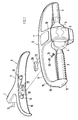
- Fig. 1 eine schaubildliche Darstellung eines zweiteiligen Lenkkopfes, bestehend aus einem Trägerteil und einem Schalenelement,
- Fig. 2 eine Draufsicht des Lenkkopfes und
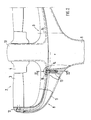
- Fig. 3 einen Schnitt nach der Linie III-III der Fig. 2 durch den Lenkkopf im Bereich des Verbindungsbereiches über die Befestigungsschrauben.
- Ein nicht näher dargesteller Hubwagen bzw. Hublader weist zum Bedienen und Fahren eine Deichsel 1 mit einem Lenkkopf 2 auf. Bieser umfaßt zwei Handgriffe 3 zum Führen und Bedienelemente zur Betätigung auf, wie z.B. einen Fahrregler 4, einen Hub- und Senkschalter 5, einen Notschalter 6 und eine Hupe 7.
- Der Lenkkopf 2 besteht aus zwei lösbar miteinander verbundenen Schalenelementen 8 und 9. Bas erste Schalenelement 8 ist ein Teil der Deichsel 1 und mit dieser einteilig ausgeführt und bildet ein Trägerteil 11 für das zweite Schalenelement 9. Dieses weist ein mittiges Horn 10 auf, das die Schalter und Regler aufnimmt und an dem die Handgriffe 3 gelagert sind, welche sich mit ihrem anderen Ende an einem einwärts gebogenen Endteil 12 des Schalenelements 9 abstützen.
- Im Trägerteil 11 sind zu beiden Seiten des Stieles der Deichsel 1 vorragende Abstütznasen 13 angeordnet, denen weitere Abstütznasen 14 des zweiten Schalenelements 9 gegenüberstehen. Bie Stirnfläche der miteinander korrespondierenden Nasen 13, 14 stützen sich aufeinander ab und sind über Befestigungsschrauben 15 miteinander verbunden.
- Die umlaufenden Stirnkanten 16, 17 der beiden Schalenelemente 8 und 9 sind ineinandergreifendend ausgeführt, so daß sich eine durchgehende bündige Außenoberfläche zwischen dem ersten und dem zweiten Schalenelement 8 und 9 ergibt. Hierzu weist das zweite Schalenelement 8 an seinem abgewinkelten Verbindungsschenkel 18 eine umlaufende Kante 17 mit einer Absetzung 19 auf, in der die umlaufende Kante 16 des Trägerteils 11 formschlüssig liegt.
- Die Abstütznasen 13 und 14 der beiden Schalenelemente 8 und 9 sind mit Aufnahmebohrungen 20 für die Schrauben 15 versehen, dessen Achsen 21 mit einem Abstand a zum Schalter 4 bzw. zum Griff 3 verlaufen. Wie Fig. 3 näher zeigt ist dieser Abstand so groß gewählt, daß die Schrauben 15 mit einem Schraubenzieher 22 ohne Behinderung von Teilen des Lenkkopfes gelöst und eingeschraubt werden können. Hierdurch ist eine schnelle Auswechselbarkeit des zweiten Schalenelements 9 gewährleistet.
- Zur Trennung der elektrischen Verbindungskabel 23, 24 zwischen dem Trägerteil 11 und dem zweiten Schalenelement 9 sind die elektrischen Leitungen über Stecker 25, 26 miteinander verbindbar.
Claims (5)
Applications Claiming Priority (2)
| Application Number | Priority Date | Filing Date | Title |
|---|---|---|---|
| DE3840801 | 1988-12-01 | ||
| DE3840801A DE3840801A1 (de) | 1988-12-01 | 1988-12-01 | Deichsel fuer von hand gefuehrte hubwagen und -lader |
Publications (3)
| Publication Number | Publication Date |
|---|---|
| EP0371227A2 true EP0371227A2 (de) | 1990-06-06 |
| EP0371227A3 EP0371227A3 (de) | 1991-08-28 |
| EP0371227B1 EP0371227B1 (de) | 1994-01-05 |
Family
ID=6368413
Family Applications (1)
| Application Number | Title | Priority Date | Filing Date |
|---|---|---|---|
| EP89117560A Expired - Lifetime EP0371227B1 (de) | 1988-12-01 | 1989-09-22 | Deichsel für von Hand geführte Hubwagen und -lader |
Country Status (4)
| Country | Link |
|---|---|
| US (1) | US5033326A (de) |
| EP (1) | EP0371227B1 (de) |
| JP (1) | JPH02189611A (de) |
| DE (2) | DE3840801A1 (de) |
Cited By (2)
| Publication number | Priority date | Publication date | Assignee | Title |
|---|---|---|---|---|
| DE19523921A1 (de) * | 1995-06-30 | 1997-01-02 | Jungheinrich Ag | Deichsel für kraftgetriebene Flurförderzeuge |
| DE4408777C2 (de) * | 1994-03-15 | 2002-11-07 | Crown Gabelstapler Gmbh | Deichsel für ein handgeführtes Flurförderfahrzeug |
Families Citing this family (13)
| Publication number | Priority date | Publication date | Assignee | Title |
|---|---|---|---|---|
| DE4444772C2 (de) * | 1994-12-15 | 2000-09-07 | Linde Ag | Deichselkopf für ein deichselgelenktes Flurförderzeug |
| USD384478S (en) | 1995-09-29 | 1997-09-30 | Jungheinrich Ag | Control handle for lift trucks |
| DE19601694C2 (de) * | 1996-01-18 | 2001-11-08 | Still Wagner Gmbh & Co Kg | Deichsel für ein Flurförderzeug |
| SE518831E1 (sv) * | 1998-12-30 | 2015-06-23 | Toyota Material Handling Europe Ab | Anordning vid ledarmstruck |
| DE102004006947A1 (de) * | 2004-02-12 | 2005-09-01 | Still Gmbh | Bedienanordnung einer mobilen Arbeitsmaschine |
| US7325655B2 (en) * | 2004-08-12 | 2008-02-05 | Jungheinrich Aktiengesellschaft | Steering arm for a walking/rider pallet truck |
| DE102004042226A1 (de) * | 2004-09-01 | 2006-03-02 | Jungheinrich Ag | Deichsel für einen Mitgeh- und Mitfahrstapler |
| US7641020B2 (en) * | 2005-04-18 | 2010-01-05 | Jungheinrich Aktiengessellschaft | Hand rail for a walkie/rider truck |
| JP2006340839A (ja) * | 2005-06-08 | 2006-12-21 | Olympus Medical Systems Corp | 超音波処置用スイッチ装置および医療機器用スイッチ装着システム |
| DE102006031967A1 (de) * | 2006-07-11 | 2008-01-17 | Jungheinrich Aktiengesellschaft | Bedienanordnung in einem Flurförderzeug |
| WO2011139825A2 (en) | 2010-04-29 | 2011-11-10 | Diversey, Inc. | Floor cleaning tool and method |
| DE202013003571U1 (de) * | 2013-04-16 | 2014-07-18 | Gebrüder Frei GmbH & Co. | Deichselkopf |
| DE102019101863A1 (de) | 2019-01-25 | 2020-07-30 | Jungheinrich Aktiengesellschaft | Bedienkopf für ein Flurförderzeug |
Citations (2)
| Publication number | Priority date | Publication date | Assignee | Title |
|---|---|---|---|---|
| GB2009066A (en) * | 1977-12-05 | 1979-06-13 | Jungheinrich Kg | A Tiller Arrangement for Tiller Controlled Vehicles |
| US4444284A (en) * | 1979-05-18 | 1984-04-24 | Big Joe Manufacturing Company | Control system |
Family Cites Families (15)
| Publication number | Priority date | Publication date | Assignee | Title |
|---|---|---|---|---|
| US2850003A (en) * | 1957-08-28 | 1958-09-02 | Fmc Corp | Starting mechanism for power lawnmowers |
| US2960886A (en) * | 1959-01-26 | 1960-11-22 | Toro Mfg Corp | Instantly retardable preset throttle control mechanism |
| US3187829A (en) * | 1963-01-29 | 1965-06-08 | Yale & Towne Inc | Brake and handle control for industrial truck |
| US3190994A (en) * | 1963-10-31 | 1965-06-22 | Shepard Co Lewis | Cam-actuated control switch mounting for motorized lift truck |
| DE2319618C2 (de) * | 1973-04-18 | 1984-11-22 | Ernst Wagner Kg, 7410 Reutlingen | Flurförderzeug mit einer Deichsel für automatischen und/oder Handbetrieb |
| JPS5317368Y2 (de) * | 1974-07-29 | 1978-05-10 | ||
| JPS5198830A (de) * | 1975-02-24 | 1976-08-31 | ||
| US4174473A (en) * | 1978-05-04 | 1979-11-13 | Aktiebolaget Electrolux | Safety switch for floor treatment apparatus |
| US4198721A (en) * | 1978-07-03 | 1980-04-22 | Servicemaster Industries, Inc. | Combination motor and auxiliary mechanism actuator |
| DE2932238A1 (de) * | 1979-08-09 | 1981-02-26 | Merit Werk Merten & Co Kg | Kombinationsschalter fuer zweiraeder, insbesondere motorraeder, mopeds und mofas |
| US4384497A (en) * | 1980-09-04 | 1983-05-24 | Indus Wheel Company, A Division Of Carlisle Corp. | Adjustable handlebar system |
| DE3370307D1 (en) * | 1982-04-22 | 1987-04-23 | Bridgestone Cycle Co | Adjustable handlebar for bicycle |
| JPS59227535A (ja) * | 1983-06-04 | 1984-12-20 | Aisin Seiki Co Ltd | 集中制御式ステアリングホイ−ル装置 |
| JPS604852U (ja) * | 1983-06-23 | 1985-01-14 | 松下電器産業株式会社 | 掘こたつ |
| JPS60107279A (ja) * | 1983-11-14 | 1985-06-12 | 富士重工業株式会社 | ケ−ブルコネクタ |
-
1988
- 1988-12-01 DE DE3840801A patent/DE3840801A1/de active Granted
-
1989
- 1989-09-22 EP EP89117560A patent/EP0371227B1/de not_active Expired - Lifetime
- 1989-09-22 DE DE89117560T patent/DE58906643D1/de not_active Expired - Fee Related
- 1989-11-29 JP JP1307820A patent/JPH02189611A/ja active Pending
- 1989-11-30 US US07/443,364 patent/US5033326A/en not_active Expired - Fee Related
Patent Citations (2)
| Publication number | Priority date | Publication date | Assignee | Title |
|---|---|---|---|---|
| GB2009066A (en) * | 1977-12-05 | 1979-06-13 | Jungheinrich Kg | A Tiller Arrangement for Tiller Controlled Vehicles |
| US4444284A (en) * | 1979-05-18 | 1984-04-24 | Big Joe Manufacturing Company | Control system |
Cited By (3)
| Publication number | Priority date | Publication date | Assignee | Title |
|---|---|---|---|---|
| DE4408777C2 (de) * | 1994-03-15 | 2002-11-07 | Crown Gabelstapler Gmbh | Deichsel für ein handgeführtes Flurförderfahrzeug |
| DE19523921A1 (de) * | 1995-06-30 | 1997-01-02 | Jungheinrich Ag | Deichsel für kraftgetriebene Flurförderzeuge |
| DE19523921C2 (de) * | 1995-06-30 | 2001-11-29 | Jungheinrich Ag | Deichsel für kraftgetriebene Flurförderzeuge |
Also Published As
| Publication number | Publication date |
|---|---|
| DE58906643D1 (de) | 1994-02-17 |
| DE3840801C2 (de) | 1991-02-07 |
| DE3840801A1 (de) | 1990-06-07 |
| JPH02189611A (ja) | 1990-07-25 |
| EP0371227A3 (de) | 1991-08-28 |
| US5033326A (en) | 1991-07-23 |
| EP0371227B1 (de) | 1994-01-05 |
Similar Documents
| Publication | Publication Date | Title |
|---|---|---|
| EP0371227B1 (de) | Deichsel für von Hand geführte Hubwagen und -lader | |
| EP3105109A1 (de) | Breitenverstellbares modulares schwerlastfahrzeug und querrahmenmodul für ein derartiges schwerlastfahrzeug | |
| EP0089633A1 (de) | Vorrichtung zum lösbaren Befestigen von Gestängen in Stützplatinen | |
| DE2208081A1 (de) | Kraftfahrzeughebebuhne | |
| DE3933825A1 (de) | Antriebsverbindung fuer den arm eines scheibenwischers | |
| DE2912783C2 (de) | Vorrichtung zum Synchronführen der Lastgehänge eines mit Aufhängegliedern versehenen Kreiskettenförderers und Lastkraftwagen eines Schleppkettenförderers | |
| DE3127019C2 (de) | "Vorrichtung für einen Schubmast-Hublader mit in Fahrzeugrichtung längsbeweglichgehaltenem Batteriewagen" | |
| DE10316403B4 (de) | Schubmaststapler | |
| DE4244010A1 (de) | Zunge | |
| AT390890B (de) | Antriebseinrichtung fuer schienenfahrzeuge mit einem adhaesions- und zahnradantrieb | |
| DE2205084A1 (de) | Steckkarte mit elektronischem Schaltungsaufbau | |
| DE2522838C2 (de) | Spurkettenfahrzeug | |
| DE2811296A1 (de) | Kettenschuhanordnung | |
| DE4241158C1 (de) | Parkpalette | |
| DE3014504A1 (de) | Bremsvorrichtung fuer von hand bediente hublader | |
| DE3111466A1 (de) | Verstellvorrichtung zum verstellen eines sitzes, insbesondere eines kraftfahrzeugsitzes | |
| EP0686102B1 (de) | Lenkstockschalter für kraftfahrzeuge | |
| DE69922337T2 (de) | Schwenkbarer Radkeil für Fahrzeugtransporter | |
| DE3242568A1 (de) | Einstellbare fuehrungsrollenanordnung bei einem hublader | |
| EP0607954B2 (de) | Schienensystem für Flurtransportanlagen | |
| EP3763605B1 (de) | Traktor mit radhaus | |
| CH630857A5 (en) | Displacement device for the fifth-wheel coupling on a semitrailer motor vehicle | |
| EP0361094A1 (de) | Zusatzvorrichtung für ein Zugfahrzeug, insbesondere einen Geländewagen | |
| EP1982949B1 (de) | Ballastvorrichtung | |
| DE3511656A1 (de) | Einrichtung zum gleichmaessigen heben und senken einer langgestreckten last |
Legal Events
| Date | Code | Title | Description |
|---|---|---|---|
| PUAI | Public reference made under article 153(3) epc to a published international application that has entered the european phase |
Free format text: ORIGINAL CODE: 0009012 |
|
| AK | Designated contracting states |
Kind code of ref document: A2 Designated state(s): DE FR GB IT SE |
|
| PUAL | Search report despatched |
Free format text: ORIGINAL CODE: 0009013 |
|
| AK | Designated contracting states |
Kind code of ref document: A3 Designated state(s): DE FR GB IT SE |
|
| 17P | Request for examination filed |
Effective date: 19911223 |
|
| 17Q | First examination report despatched |
Effective date: 19920623 |
|
| ITF | It: translation for a ep patent filed |
Owner name: DE DOMINICIS & MAYER S. |
|
| GRAA | (expected) grant |
Free format text: ORIGINAL CODE: 0009210 |
|
| AK | Designated contracting states |
Kind code of ref document: B1 Designated state(s): DE FR GB IT SE |
|
| REF | Corresponds to: |
Ref document number: 58906643 Country of ref document: DE Date of ref document: 19940217 |
|
| GBT | Gb: translation of ep patent filed (gb section 77(6)(a)/1977) |
Effective date: 19940323 |
|
| EN | Fr: translation not filed | ||
| PLBE | No opposition filed within time limit |
Free format text: ORIGINAL CODE: 0009261 |
|
| STAA | Information on the status of an ep patent application or granted ep patent |
Free format text: STATUS: NO OPPOSITION FILED WITHIN TIME LIMIT |
|
| ET | Fr: translation filed | ||
| 26N | No opposition filed | ||
| REG | Reference to a national code |
Ref country code: FR Ref legal event code: R1 |
|
| EAL | Se: european patent in force in sweden |
Ref document number: 89117560.6 |
|
| REG | Reference to a national code |
Ref country code: FR Ref legal event code: R1 |
|
| PGFP | Annual fee paid to national office [announced via postgrant information from national office to epo] |
Ref country code: SE Payment date: 19970829 Year of fee payment: 9 |
|
| PGFP | Annual fee paid to national office [announced via postgrant information from national office to epo] |
Ref country code: FR Payment date: 19980828 Year of fee payment: 10 |
|
| PGFP | Annual fee paid to national office [announced via postgrant information from national office to epo] |
Ref country code: DE Payment date: 19980909 Year of fee payment: 10 |
|
| PGFP | Annual fee paid to national office [announced via postgrant information from national office to epo] |
Ref country code: GB Payment date: 19980915 Year of fee payment: 10 |
|
| PG25 | Lapsed in a contracting state [announced via postgrant information from national office to epo] |
Ref country code: SE Free format text: LAPSE BECAUSE OF NON-PAYMENT OF DUE FEES Effective date: 19980923 |
|
| EUG | Se: european patent has lapsed |
Ref document number: 89117560.6 |
|
| PG25 | Lapsed in a contracting state [announced via postgrant information from national office to epo] |
Ref country code: GB Free format text: LAPSE BECAUSE OF NON-PAYMENT OF DUE FEES Effective date: 19990922 |
|
| GBPC | Gb: european patent ceased through non-payment of renewal fee |
Effective date: 19990922 |
|
| PG25 | Lapsed in a contracting state [announced via postgrant information from national office to epo] |
Ref country code: FR Free format text: LAPSE BECAUSE OF NON-PAYMENT OF DUE FEES Effective date: 20000531 |
|
| PG25 | Lapsed in a contracting state [announced via postgrant information from national office to epo] |
Ref country code: DE Free format text: LAPSE BECAUSE OF NON-PAYMENT OF DUE FEES Effective date: 20000701 |
|
| REG | Reference to a national code |
Ref country code: FR Ref legal event code: ST |
|
| PG25 | Lapsed in a contracting state [announced via postgrant information from national office to epo] |
Ref country code: IT Free format text: LAPSE BECAUSE OF NON-PAYMENT OF DUE FEES Effective date: 20050922 |