EP0357871A2 - Formmaschine - Google Patents
Formmaschine Download PDFInfo
- Publication number
- EP0357871A2 EP0357871A2 EP89108368A EP89108368A EP0357871A2 EP 0357871 A2 EP0357871 A2 EP 0357871A2 EP 89108368 A EP89108368 A EP 89108368A EP 89108368 A EP89108368 A EP 89108368A EP 0357871 A2 EP0357871 A2 EP 0357871A2
- Authority
- EP
- European Patent Office
- Prior art keywords
- molding machine
- machine according
- lifting
- stand
- piston
- Prior art date
- Legal status (The legal status is an assumption and is not a legal conclusion. Google has not performed a legal analysis and makes no representation as to the accuracy of the status listed.)
- Granted
Links
- 238000000465 moulding Methods 0.000 title claims abstract description 85
- 238000007906 compression Methods 0.000 claims abstract description 28
- 230000006835 compression Effects 0.000 claims abstract description 26
- 230000008878 coupling Effects 0.000 claims description 12
- 238000010168 coupling process Methods 0.000 claims description 12
- 238000005859 coupling reaction Methods 0.000 claims description 12
- 238000000034 method Methods 0.000 abstract description 16
- 238000000748 compression moulding Methods 0.000 abstract description 3
- 239000003110 molding sand Substances 0.000 description 10
- 239000004576 sand Substances 0.000 description 5
- 238000011161 development Methods 0.000 description 4
- 238000004519 manufacturing process Methods 0.000 description 4
- 238000005056 compaction Methods 0.000 description 3
- 230000002349 favourable effect Effects 0.000 description 3
- 239000012778 molding material Substances 0.000 description 3
- 238000005266 casting Methods 0.000 description 2
- 239000012530 fluid Substances 0.000 description 2
- 238000012986 modification Methods 0.000 description 2
- 230000004048 modification Effects 0.000 description 2
- 230000006978 adaptation Effects 0.000 description 1
- 238000013459 approach Methods 0.000 description 1
- 239000000969 carrier Substances 0.000 description 1
- 238000010276 construction Methods 0.000 description 1
- 238000013461 design Methods 0.000 description 1
- 230000000694 effects Effects 0.000 description 1
- 239000010720 hydraulic oil Substances 0.000 description 1
- 238000003825 pressing Methods 0.000 description 1
- 238000007789 sealing Methods 0.000 description 1
Images

Classifications
-
- B—PERFORMING OPERATIONS; TRANSPORTING
- B22—CASTING; POWDER METALLURGY
- B22C—FOUNDRY MOULDING
- B22C11/00—Moulding machines characterised by the relative arrangement of the parts of same
- B22C11/02—Machines in which the moulds are moved during a cycle of successive operations
- B22C11/04—Machines in which the moulds are moved during a cycle of successive operations by a horizontal rotary table or carrier
Definitions
- the invention relates to a molding machine with a stand, a compression device and at least one lifting device.
- the work steps required to produce a mold include placing a molding box on a model plate and placing a sand filling frame on the molding box. These two operations are usually carried out by hand. Subsequently, sand is filled into the molding box through the filling frame, this usually being done by means of a manually operated conveyor. After sufficient sand filling, the sand is pre-compacted in the mold, usually using vibrators. After swiveling in a counterpressure plate, the molding sand is post-processed in a pressing process seals.
- the known molding machines also prove to be disadvantageous with regard to the compression methods used, since, in particular in the case of smaller molding machines, the mold is precompressed by shaking, which on the one hand leads to high noise emissions and on the other hand to high wear on both the molding machines and the molding boxes and Models leads.
- the invention has for its object to provide a molding machine of the type mentioned, which allows a rational and time-saving manufacture of a castable mold with a simple structure and simple, reliable handling.
- a rotating table unit comprising at least two tables is mounted on the stand, which has an ab in the area of each table has lifting device, and that the compression device is formed on the stand.
- the molding machine according to the invention is characterized by a number of considerable advantages.
- the rotary table unit comprising several tables makes it possible to carry out predetermined work steps independently of one another on each of the tables. For example, the molding sand can be compacted on one of the tables, while molding sand is filled in on the other table or a finished mold is lifted off.
- two tables it is also possible to produce an upper box shape or a lower box shape on each table, so that a complete castable mold can be produced on a molding machine.
- Another advantage of the molding machine according to the invention is that the operator can carry out his work without any time interruption, since, in contrast to the molding machines known from the prior art, the further work processes can be carried out on the other table during the sealing process.
- Another advantage of the molding machine according to the invention results from the fact that it is independent of the method used to compact the molding sand or molding material is, so that it is possible to compact the molding sand in a conventional manner by shaking, as well as by means of an air flow press molding process.
- the turntable unit comprises a support device for a molding box in the area of the tables.
- the support device transfers the forces applied when compacting the molding sand or molding material directly to the stand; the turntable unit itself is not loaded. This leads to the possibility of dimensioning the turntable unit much smaller.
- the support unit preferably has a support piston, which is mounted below the table and can be brought into abutment against the stand, and a lifting piston which moves the table against the compression device arranged in the upper region of the stand.
- the compression process thus includes both supporting the molding box or the table on the stand and lifting the molding box or the table against the compression device arranged in the upper region of the stand.
- This configuration enables, in addition to the already mentioned support, which avoids the application of force to the turntable unit, a space-saving configuration of the molding machine and, in particular in the area in which the table or the turntable unit is pivoted relative to the stand, to provide sufficient free space.
- by lifting the table it is not necessary to lower the compression device itself or to approach the molding box. Rather, the compression device can be attached essentially stationary to the upper area of the stand.
- the support piston comprises a tubular, movable to the table lifting cylinder, in which the piston, which is designed in the form of a double-acting piston, arranged is, wherein the piston rod of the reciprocating piston is connected to the table.
- the piston which is designed in the form of a double-acting piston, arranged is, wherein the piston rod of the reciprocating piston is connected to the table.
- the table is connected to a table guide rod which can be displaced in a recess in the rotary table unit.
- the lifting device is preferably designed such that a lifting cylinder is mounted on the turntable unit in the region of the table, the piston rod of which is connected to lifting pins by means of a lifting cross-piece connected to this.
- a lifting cylinder is mounted on the turntable unit in the region of the table, the piston rod of which is connected to lifting pins by means of a lifting cross-piece connected to this.
- Lifting guide rods are preferably mounted on the lifting crossmember, at the free ends of which a carrier is fastened, which carries the lifting pin.
- the stand in the region of the working position of the table assigned to the compacting device comprises a support device for a molding box.
- the turntable unit is interposed, or independently of it, with appropriate support of the table.
- the support device comprises at least one piston mounted on the stand, the piston rod of which can be brought into contact with the table.
- a movable table guide rod which can be connected to the table and the piston rod, is mounted on the rotary table unit.
- the invention provides that the reciprocating piston can be coupled to the table. This can be done in that the piston rod is provided at its upper end with a coupling body which can be brought into engagement with the table guide rod.
- a lifting device is arranged on a working position of the table assigned to the filling side of the frame.
- this can be designed in such a way that a universally displaceable piston rod is provided which can be coupled to a lifting traverse which is displaceably mounted on the turntable unit and at the free ends of which a carrier is fastened which carries a lifting pin.
- the upper end of the piston rod has a coupling body which can be brought into engagement with the lifting traverse.
- the coupling body can be positively inserted into a groove in the lifting crossmember or the table guide rod is.
- the coupling body can be designed, for example, in the form of a thickened extension, which can be introduced into a dovetail-shaped or U-shaped groove.
- the stand is essentially C-shaped in the side view.
- the turntable unit can be pivoted about a vertical axis, the pivot axis being arranged on the outer region of the C-shaped stand, so that in each case one table of the turntable unit can be pivoted into the free space of the stand.
- both a compact design of the molding machine is possible, as is a construction of particular strength, since the C-shaped stand is additionally supported via the vertical axis of the turntable unit.
- a filling station, a lifting station and / or an auxiliary compaction station can also be arranged on the outer area of the stand in order to place a new molding box on the table, which is not under the compacting device arranged on the stand, to place a new molding box on this, a filling frame to arrange, add sand and pre-compact.
- the compression device is designed such that it comprises a press plate which is arranged displaceably in the interior of a press box which can be pressurized with compressed air. It is thus possible to use an airflow press molding method in which the molding box does not have to be shaken.
- the press plate is connected to a double-acting plunger and a guide rod guided in the stand. This embodiment ensures both exact guidance of the press plate and simple hydraulic controllability.
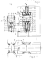
- the molding machine according to the invention has a stand 1 which has a substantially C-shaped cross section in the side view.
- the free ends of the C-shaped stand 1 are connected via a vertical axis 35 which is fixedly mounted on the stand 1 and which carries a turntable unit 3 which can be pivoted about the axis 36.
- the turntable unit 3 has two tables 9, which are each mounted on the top of the turntable unit 3.
- a model plate 22 can be placed on each of the tables 9, which is provided in the usual way with a model 23. As shown in FIG. 1, a molding box 24, which forms a molding cavity 27, can be placed on the model plate 22. A filling frame 25 is usually placed on the molding box 24, which facilitates the filling of the molding sand.
- a lifting and supporting device is arranged on the turntable unit 3 below the table 9.
- This comprises a reciprocating piston 12 which is connected to a piston rod 11, which in turn is attached to the table 9.
- the lifting piston 12 is designed in the form of a double-acting piston and can be moved in a lifting cylinder 10, the lower region of which has a supporting piston 13.
- the supporting piston 13 of the lifting cylinder 10 which is mounted on the rotary table unit 3 and is displaceable relative to it, is first moved downwards until it is in contact with a supporting plate 26 of the stand 1.
- this pressurization causes the reciprocating piston 12 and thus also the table 9 to be moved upward, so that the filling frame 25 is pressed against a compression device which is formed on the upper region of the stand 1.
- the compression device is described in detail below.
- the table 9 In order to prevent the table 9 from rotating, it has at least one table guide rod 14 which can be displaced in a recess in the rotary table unit 3.
- the compression device comprises a press box 15, which is provided with a recess in which a press plate 16 is arranged.
- the recess of the press box 15 is adapted to the size of the filling frame 25 or the molding box 24.
- a press frame 20 can also be arranged on the underside of the press box, as shown in FIG. 1.
- the bottom of the press frame 20 is with provided with a press seal 21, which ensures an airtight seal when the filling frame 25 bears against the press frame 20.
- the press frame 15 is fixedly connected to the stand 1 and has an air inlet 19 through which compressed air can be pressed into the interior 28 of the press box 15 and thus into the mold cavity 27.
- the press plate 16 is connected via a piston rod to a press piston 35 which is movable in a press cylinder 17 and is in the form of a double-acting piston. It is thus possible to lower or raise the press plate.
- a guide rod 18 which is guided displaceably in a recess in the stand or the press box 15.
- the compression device described above thus allows the use of an air flow compression molding process.
- a lifting device is also provided in the area under each table 9, which comprises a lifting cylinder 4, a lifting crossbar 5 connected to this and lifting guide rods 6, which are connected to the lifting crossbar 5.
- a lifting cylinder 4 By actuating the lifting cylinder 4, it is thus possible to lower or raise the lifting crossbeam 5 and thus the guide rods 6.
- a carrier 7 At the upper ends of the guide rods 6, a carrier 7 is releasably attached, on which a lifting pin 8 is mounted. By adjusting the position of the carriers 7, it is possible to adapt the lifting device to the respective shape and configuration of the molding boxes 24 or the filling frames 25.
- the piston connected to the lifting crossbar 5 via the piston rod 34 enables a precisely controllable lifting of the finished form or of the molding box 24 from the model plate 22.
- the pivoting of the turntable unit 3 can be done manually in smaller molding machines, but it is also possible to provide an auxiliary drive for pivoting the turntable unit 3. Furthermore, locking devices can be provided in order to ensure an exact positioning of the tables 9. Since the piston 12 is in the form of a double-acting piston, it is ensured in the position ready for pivoting shown in FIG. 1 that the supporting piston 13 does not bear against the supporting plate 26, so that the rotary table unit 3 can pivot freely.
- molding machine By means of the molding machine according to the invention, it is now possible to lift a filled molding box 24 in the region of a lifting station marked 31 and to replace it with an empty molding box. Furthermore, molding sand can be fed into this lifting station, for example from the operating side 29. While these operations are taking place, it is possible to compress the molding sand accordingly in the area of the compression side 30.
- FIG. 2 shows an end view of the molding machine shown in FIG. 1, but the illustration of the molding box and the filling frame has been omitted.
- FIG. 3 shows a top view of the molding machine according to the invention, which is also not equipped with a molding box or a filling frame.
- the arrows 32 and 33 indicate the pivotability of the turntable unit 3.
- the mold cavity and thus the molding sand located therein is formed by introducing compressed air through the air inlet 19 pre-compressed. Subsequently, a compression is carried out by means of the pressure plate 16. The pressure box cavity 28 is then vented via the air inlet 19, whereupon the pressure plate 16 is withdrawn by the piston 35.
- the second exemplary embodiment differs from the first described exemplary embodiment in that below the filling side and the compaction side the respective lifting and supporting devices are not arranged on the turntable unit but on the frame.
- a number of reciprocating pistons 12 are mounted in cylinders 37 on the compression side on the frame below the turntable unit.
- the lifting pistons 12 each have a coupling at their upper end, which enables a connection to the table guide rods 14, which are mounted on the turntable unit 3 so as to be vertically displaceable.
- the turntable unit 3 has a bearing bush arrangement 38.
- a vertically displaceable piston rod 34 with an associated piston is mounted in a cylinder 39 on the lower part of the frame 1.
- the upper end of the piston rod 34 can be coupled to an extension of a push-off crossbar 5, which in turn has free ends, as shown in particular in FIG. Has carrier 7, which are connected to lifting pins 8.
- the piston rod 34 or 11 Since not only a vertical upward movement but also a return movement is to be carried out by means of the piston rod 34 or the reciprocating piston 12, the piston rod 34 or 11 has at its upper end a coupling body 26 which is in the form of a thickened head region is and can be inserted into a groove 39 of the element to be coupled, for example the table guide rod 14.
- the groove 39 extends transversely through the respective element, so that when the turntable unit 3 rotates, the coupling body 26 can be inserted into the groove 39. It is therefore not necessary to take additional clutch measures and / or to manually disengage or engage a clutch.
Landscapes
- Engineering & Computer Science (AREA)
- Mechanical Engineering (AREA)
- Casting Devices For Molds (AREA)
- Casting Or Compression Moulding Of Plastics Or The Like (AREA)
- Injection Moulding Of Plastics Or The Like (AREA)
- Permanent Magnet Type Synchronous Machine (AREA)
- Presses And Accessory Devices Thereof (AREA)
Abstract
Description
- Die Erfindung bezieht sich auf eine Formmaschine mit einem Ständer, einer Verdichtungseinrichtung und zumindest einer Abhebeeinrichtung.
- Zur Herstellung von Formen werden in Gießereien vielfach jeweils separate Maschinen verwendet, welche zu Befüllung eines Formkastens, zur Verdichtung des Formstoffes und zum Abheben der Form dienen. Dabei ist es bekannt, den Verdichtungsvorgang und den Abhebevorgang durch eine Maschine durchführen zu lassen, welcher jeweils ein gefüllter Formkasten, welcher auf einer Modellplatte aufliegt, zugeführt wird.
- Bei den bekannten Formmaschinen ist es erforderlich, eine Vielzahl von einzelnen Arbeitsgängen nacheinander von Hand durchzuführen oder, bei Verwendung teilautomatisierter Maschinen, von Hand zu überwachen. Die zur Herstellung einer Form erforderlichen Arbeitsgänge umfassen das Aufsetzen eines Formkastens auf eine Modellplatte, sowie das Aufsetzen eines Sandfüllrahmens auf den Formkasten. Diese beiden Arbeitsgänge werden üblicherweise von Hand durchgeführt. Anschließend wird durch den Füllrahmen Sand in den Formkasten eingefüllt, wobei dies üblicherweise mittels einer manuell zu bedienenden Fördereinrichtung vorgenommen wird. Nach einer ausreichenden Sandbefüllung erfolgt ein Vorverdichten des Sandes in der Form, wobei dazu üblicherweise Rüttler verwendet werden. Nach dem Einschwenken einer Gegenpreßplatte wird der Formsand in einem Preßvorgang nachver dichtet. Anschließend ist es erforderlich, die Preßplatte von dem Formkasten zu entfernen, um anschließend mittels einer Abhebevorrichtung die Form von dem Modell bzw. von der Modellplatte zu trennen. Diese Arbeitsgänge erfordern eine Vielzahl von manuellen Tätigkeiten und sind deshalb bei den bisher bekannten Formmaschinen nicht oder nur unter erheblichem Aufwand weiter zu rationalisieren und/oder zu automatisieren.
- Ein weiterer Nachteil der bekannten Formmaschinen bzw. der bei diesen verwendeten Verfahren besteht darin, daß die Herstellung einer Oberkastenform und einer Unterkastenform auf getrennten Formmaschinen erfolgt. Dies bringt den Nachteil, daß zum einen die Herstellungszeiten für eine gießfertige Form sehr hoch sind und daß zum anderen sowohl die Koordination der Betriebsweise der beiden Formmaschinen als auch die Koordination der Transportvorgänge einen erheblichen Aufwand mit sich bringen.
- Auch hinsichtlich der zur Anwendung kommenden Verdichtungsverfahren erweisen sich die bekannten Formmaschinen als nachteilig, da insbesondere bei kleineren Formmaschinen ein Vorverdichten der Form durch Rütteln erfolgt, was zum einen zu einer starken Geräuschemission und zum anderen zu einem hohen Verschleiß sowohl der Formmaschinen als auch der Formkästen und Modelle führt.
- Der Erfindung liegt die Aufgabe zugrunde, eine Formmaschine der eingangs genannten Art zu schaffen, welche bei einfachem Aufbau und einfacher, betriebssicherer Handhabbarkeit eine rationelle und zeitsparende Fertigung einer gießfertigen Form ermöglicht.
- Erfindungsgemäß wird die Aufgabe dadurch gelöst, daß am Ständer eine zumindest zwei Tische umfassende Drehtischeinheit gelagert ist, welche im Bereich jeden Tisches eine Ab hebeeinrichtung aufweist, und daß die Verdichtungseinrichtung am Ständer ausgebildet ist.
- Die erfindungsgemäße Formmaschine zeichnet sich durch eine Reihe erheblicher Vorteile aus. Durch die mehrere Tische umfassende Drehtischeinheit ist es möglich, an jedem der Tische unabhängig voneinander vorbestimmte Arbeitsgänge ablaufen zu lassen. So kann beispielsweise an einem der Tische der Formsand verdichtet werden, während an dem anderen Tisch Formsand eingefüllt oder eine fertige Form abgehoben wird. Durch die Verwendung zweier Tische ist es weiterhin möglich, jeweils auf einem Tisch eine Oberkastenform bzw. eine Unterkastenform zu erzeugen, so daß an einer Formmaschine jeweils eine komplette gießfertige Form hergestellt werden kann. Durch die Möglichkeit, die erfindungsgemäße Maschine mittels nur einer Bedienungsperson zu betreiben, ergibt sich die Möglichkeit erheblicher Einsparungen, nicht nur bezüglich der Arbeitskraft, sondern auch hinsichtlich des Transportaufwandes, da von der erfindungsgemäßen Formmaschine lediglich die fertiggestellten kompletten Gießformen abtransportiert werden müssen, während es beim Stand der Technik erforderlich war, zumindest zwei einzelne Formmaschinen mit jeweils einer Bedienungsperson zu verwenden und die Zuordnung der Oberkastenformen und Unterkastenformen zur Ausbildung einer fertigen Gießform durch eine dritte Arbeitskraft vornehmen zu lassen.
- Ein weiterer Vorteil der erfindungsgemäßen Formmaschine besteht darin, daß die Bedienungsperson ohne zeitliche Unterbrechung ihre Tätigkeit ausüben kann, da, im Gegensatz zu den aus dem Stand der Technik bekannten Formmaschinen während des Dichtungsvorganges jeweils an dem anderen Tisch die weiteren Arbeitsvorgänge durchgeführt werden können.
- Ein weiterer Vorteil der erfindungsgemäßen Formmaschine ergibt sich daraus, daß diese unabhängig von dem zur Verdichtung des Formsandes oder Formstoffes verwendeten Verfahren ist, so daß es sowohl möglich ist, den Formsand in konventioneller Weise durch Rütteln zu verdichten, als auch mittels eines Luftstrom-Preß-Formverfahrens.
- In einer weiteren, vorteilhaften Ausgestaltung der Erfindung ist vorgesehen, daß die Drehtischeinheit jeweils im Bereich der Tische eine Abstützeinrichtung für einen Formkasten umfaßt. Durch die Abstützeinrichtung werden die beim Verdichten des Formsandes oder Formstoffes aufgebrachten Kräfte direkt auf den Ständer übergeleitet, die Drehtischeinheit selbst wird dabei nicht belastet. Dies führt zu der Möglichkeit, die Drehtischeinheit wesentlich kleiner zu dimensionieren.
- Die Abstützeinheit weist bevorzugterweise einen unterhalb des Tisches gelagerten, gegen den Ständer in Anlage bringbaren Stützkolben auf, sowie einen den Tisch gegen die im oberen Bereich des Ständers angeordnete Verdichtungseinrichtung bewegenden Hubkolben. Der Verdichtungsvorgang umfaßt somit sowohl ein Abstützen des Formkastens bzw. des Tisches am Ständer, als auch ein Anheben des Formkastens bzw. des Tisches gegen die im oberen Bereich des Ständers angeordnete Verdichtungseinrichtung. Diese Ausgestaltung gibt die Möglichkeit, zusätzlich zu der bereits erwähnten, Kraftbeaufschlagungen der Drehtischeinheit vermeidenden Abstützung, eine platzsparende Ausgestaltung der Formmaschine vorzunehmen und insbesondere in dem Bereich, in welchem der Tisch bzw. die Drehtischeinheit zum Ständer verschwenkt wird, einen ausreichenden Freiraum vorzusehen. Weiterhin ist es durch das Anheben des Tisches nicht erforderlich, die Verdichtungseinrichtung selbst abzusenken oder dem Formkasten anzunähern. Vielmehr kann die Verdichtungseinrichtung im wesentlichen stationär am oberen Bereich des Ständers angebracht werden.
- Um sowohl eine Abstützung des jeweiligen Tisches als auch ein Anheben des Tisches in Richtung auf die Verdichtungs einheit auf einfache und betriebssichere Weise zu gewährleisten, kann in einer besonders vorteilhaften Weiterbildung der Erfindung vorgesehen sein, daß der Stützkolben, einen rohrförmigen, zu dem Tisch verschiebbaren Hubzylinder umfaßt, in welchem der Hubkolben, welcher in Form eines doppelt wirkenden Kolbens ausgebildet ist, angeordnet ist, wobei die Kolbenstange des Hubkolbens mit dem Tisch verbunden ist. Bei dieser Ausgestaltungsform ist es nurmehr erforderlich, mittels eines Hydraulikanschlusses die entsprechende Seite des Hubkolbens mit Drucköl zu beaufschlagen, um gleichzeitig sowohl eine Abstützung des Stützkolbens als auch ein Anheben des Tisches zu erreichen. Eine separate Steuerung ist somit nicht erfordlich.
- Um ein unbeabsichtigtes Drehen des Tisches bei dessen Anhebung in Richtung auf die Verdichtungseinrichtung zu verhindern, kann es sich als vorteilhaft erweisen, wenn der Tisch mit einer Tischführungsstange verbunden ist, welcher in einer Ausnehmung der Drehtischeinheit verschiebbar ist.
- Erfindungsgemäß ist die Abhebeeinrichtung bevorzugterweise so ausgebildet, daß an der Drehtischeinheit im Bereich des Tisches ein Abhebezylinder gelagert ist, dessen Kolbenstange über eine mit dieser verbundene Abhebetraverse mit Abhebestiften verbunden ist. Es ist somit jeder Tisch der Drehtischeinheit mit einer separaten Abhebeeinrichtung versehen, so daß es nicht erforderlich ist, zusätzliche separate Maschinen vorzusehen, welche möglicherweise auch zusätzlich in ihrer Lage zu dem Tisch einjustiert werden müßten.
- Bevorzugterweise sind an der Abhebetraverse Abhebeführungsstangen gelagert, an deren freien Enden jeweils ein Träger befestigt ist, welcher den Abhebestift trägt. Diese Ausgestaltungsform weist den Vorteil auf, daß eine Anpassung an unterschiedliche Formkästen oder Formkastengrößen sehr schnell und einfach vorgenommen werden kann, wobei es erfindungsgemäß auch möglich ist, an der Drehtischeinheit Formkästen verschiedener Größe zu bearbeiten.
- Bei der oben beschriebenen Ausführungsform ist es, da die jeweiligen Kolben und Zylinder an der Drehtischeinheit gelagert sind, erforderlich, geeignete Maßnahmen zur Druckfluidversorgung zu treffen, beispielsweise dadurch, daß die Drehachse der Drehtischeinheit mit einer Ausnehmung versehen ist, durch welche geeignete Versorgungsschläuche geführt sind. Es ist jedoch auch möglich, die Versorgungsschläuche frei zugänglich direkt der Drehtischeinheit zuzuführen. Für bestimmte Anwendungszwecke kann diese Ausgestaltgungsform deshalb gewisse Nachteile mit sich bringen. Es wird deshalb im folgenden eine modifizierte Ausführungsform beschrieben, bei welcher die Drehtischeinheit und das Gestell so ausgebildet sind, daß die mit Druckfluid zu beaufschlagenden Bauelemente nicht an der Drehtischeinheit, sondern an dem Gestell gelagert sind.
- Es ist deshalb in einer günstigen Weiterbildung der Erfindung vorgesehen, daß der Ständer im Bereich der der Verdichtungseinrichtung zugeordneten Arbeitsstellung des Tisches eine Abstützeinrichtung für einen Formkasten umfaßt. Sobald sich die Drehtischeinheit in der jeweiligen Arbeitsstellung befindet, erfolgt, unter Zwischenschaltung der Drehtischeinheit oder unabhängig von dieser eine entsprechende Abstützung des Tisches. Dabei kann es günstig sein, wenn die Abstützeinrichtung zumindest einen am Ständer gelagerten Kolben umfaßt, dessen Kolbenstange in Anlage an den Tisch bringbar ist.
- In einer besonders günstigen Weiterbildung der Erfindung ist vorgesehen, daß an der Drehtischeinheit eine verschiebbare, mit dem Tisch und der Kolbenstange in Verbindung bringbare Tischführungsstange gelagert ist.
- Um eine freie Verschwenkbarkeit der Drehtischeinheit zu gewährleisten und zugleich eine entsprechende Abstützung sicherzustellen, ist erfindungsgemäß vorgesehen, daß der Hubkolben mit dem Tisch koppelbar ist. Dies kann dadurch erfolgen, daß die Kolbenstange an ihrem oberen Ende mit einem mit der Tischführungsstange in Eingriff bringbaren Kupplungskörper versehen ist.
- Weiterhin ist es erfindungsgemäß günstig, daß an einer der Einfüllseite des Gestells zugeordneten Arbeitsstellung des Tisches eine Aushebeeinrichtung angeordnet ist. Diese kann bei dem beschriebenen Ausführungsbeispiel so ausgebildet sein, daß eine universal verschiebbare Kolbenstange vorgesehen ist, welche mit einer an der Drehtischeinheit verschiebbar gelagerten Abhebetraverse koppelbar ist, an deren freien Enden jeweils ein Träger befestigt ist, welcher einen Abhebestift trägt. Auch hierbei ist es günstig, wenn das obere Ende der Kolbenstange einen mit der Abhebetraverse in Eingriff bringbaren Kupplungskörper aufweist.
- Um bei einer Verschwenkung der Drehtischeinheit die jeweiligen Kupplungen in sicherer Weise einzurücken und um sicherzustellen, daß eine vertikale Bewegung nicht nur nach oben, sondern auch nach unten erfolgen kann, ist vorgesehen, daß der Kupplungskörper formschlüssig in eine Nut der Abhebetraverse bzw. der Tischführungsstange einschiebbar ist. Der Kupplungskörper kann beispielsweise in Form eines verdickten Ansatzes ausgebildet sein, welcher in eine schwalbenschwanzförmige oder U-förmige Nut einbringbar ist.
- In einer weiteren besonders günstigen Ausgestaltungsform ist der Ständer in der Seitenansicht im wesentlichen C-förmig ausgebildet. Dabei ist die Drehtischeinheit um eine vertikale Achse schwenkbar, wobei die Schwenkachse am Außenbereich des C-förmigen Ständers angeordnet ist, so daß jeweils ein Tisch der Drehtischeinheit in den Freiraum des Ständers einschwenkbar ist. In dieser Ausgestaltungsform ist sowohl eine kompakte Bauweise der Formmaschine möglich, als auch eine Bauweise besonderer Festigkeit, da der C-förmige Ständer eine zusätzliche Abstützung über die vertikale Achse der Drehtischeinheit erfährt.
- Am Außenbereich des Ständers können weiterhin eine Befüllungsstation, eine Abhebestation und/oder eine Hilfsverdichtungsstation angeordnet sein, um im Bereich des Tisches, welcher sich nicht unter der am Ständer angeordneten Verdichtungseinrichtung befindet, die fertige Form abzuheben, einen neuen Formkasten aufzusetzen, auf diesem einen Füllrahmen anzuordnen, Sand zuzuführen und vorzuverdichten.
- In einem bevorzugten Ausführungsbeispiel der erfindungsgemäßen Formmaschine ist die Verdichtungseinrichtung so ausgebildet, daß diese eine Preßplatte umfaßt, welche im Innenraum eines mit Druckluft beaufschlagbaren Preßkastens verschiebbar angeordnet ist. Es ist somit möglich, ein Luftstrom-Preß-Formverfahren zu verwenden, bei welchem auf ein Rütteln des Formkastens verzichtet werden kann. In einer Weiterbildung dieser Ausführungsform kann vorgesehen sein, daß die Preßplatte mit einem doppelt wirkenden Preßkolben sowie einer im Ständer geführten Führungsstange verbunden ist. Diese Ausgestaltungsform gewährleistet sowohl eine exakte Führung der Preßplatte als auch eine einfache hydraulische Ansteuerbarkeit.
- Erfindungsgemäß ist es jedoch auch möglich, eine Verdichtungseinrichtung in Form einer nach dem Rüttel-Preß-Verdichtungsverfahren arbeitenden Rütteleinrichtung zu verwenden.
- Im folgenden wird die Erfindung anhand eines Ausführungsbeispiels in Verbindung mit der Zeichnung beschrieben. Dabei zeigt:
- Fig. 1 eine schematische Seitenansicht, teils im Schnitt, eines Ausführungsbeispiels der erfindungsgemäßen Formmaschine;
- Fig. 2 eine stirnseitige Ansicht der in Fig. 1 gezeigten Formmaschine;
- Fig. 3 eine Draufsicht auf die in Fig. 1 gezeigte Formmaschine;
- Fig. 4 eine schematische Seitenansicht eines weiteren Ausführungsbeispiels der erfindungsgemäßen Formmaschine, in ähnlicher Ansicht wie Fig. 1;
- Fig. 5 eine Draufsicht, in vereinfachter Form, auf das in Fig. 4 dargestellte Ausführungsbeispiel;
- Fig. 6 eine stirnseitige Ansicht des Ausführungsbeispiels der Fig. 4 und 5 und
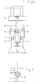
- Fig. 7 eine Detailansicht der Kupplung zwischen der Kolbenstange 11 und der Tischführungsstange 14.
- Die erfindungsgemäße Formmaschine weist einen Ständer 1 auf, welcher in der Seitenansicht einen im wesentlichen C-förmigen Querschnitt aufweist. Die freien Enden des C-förmigen Ständers 1 sind über eine vertikale Achse 35 verbunden, welche fest an dem Ständer 1 gelagert ist und welche eine Drehtischeinheit 3 trägt, die um die Achse 36 verschwenkbar ist.
- Die Drehtischeinheit 3 weist zwei Tische 9 auf, welche jeweils an der Oberseite der Drehtischeinheit 3 gelagert sind.
- Auf jeden der Tische 9 ist eine Modellplatte 22 auflegbar, welche in üblicher Weise mit einem Modell 23 versehen ist. Wie in Fig. 1 gezeigt, kann auf die Modellplatte 22 ein Formkasten 24 aufgestellt werden, welcher einen Formhohlraum 27 bildet. Auf den Formkasten 24 wird üblicherweise ein Füllrahmen 25 aufgesetzt, welcher das Einfüllen des Formsandes erleichtert.
- Unterhalb des Tisches 9 ist an der Drehtischeinheit 3 jeweils eine Hebe- und Abstützeinrichtung angeordnet. Diese umfaßt einen Hubkolben 12, welcher mit einer Kolbenstange 11 verbunden ist, welche wiederum an dem Tisch 9 befestigt ist. Der Hubkolben 12 ist in Form eines doppelt wirkenden Kolbens ausgebildet und ist in einem Hubzylinder 10 bewegbar, dessen unterer Bereich einen Stützkolben 13 aufweist. Durch Druckbeaufschlagung des Arbeitsraumes unterhalb des Hubkolbens 12 wird zunächst der Stützkolben 13 des Hubzylinders 10, welcher an der Drehtischeinheit 3 gelagert und relativ zu dieser verschiebbar ist, nach unten bewegt, bis er sich in Anlage an einer Stützplatte 26 des Ständers 1 befindet. Außerdem wird durch diese Druckbeaufschlagung der Hubkolben 12 und damit auch der Tisch 9 nach oben verschoben, so daß der Füllrahmen 25 gegen eine Verdichtungseinrichtung gedrückt wird, welche am oberen Bereich des Ständers 1 ausgebildet ist. Die Verdichtungseinrichtung wird nachfolgend im einzelnen noch beschrieben. Um eine Verdrehung des Tisches 9 zu verhindern, weist dieser zumindest eine Tischführungsstange 14 auf, welche in einer Ausnehmung der Drehtischeinheit 3 verschiebbar ist.
- Die Verdichtungseinrichtung umfaßt einen Preßkasten 15, welcher mit einer Ausnehmung versehen ist, in welcher eine Preßplatte 16 angeordnet ist. Die Ausnehmung des Preßkastens 15 ist der Größe des Füllrahmens 25 bzw. des Formkastens 24 angepaßt. An der Unterseite des Preßkastens kann zusätzlich ein Preßrahmen 20 angeordnet sein, so wie dies in Fig. 1 dargestellt ist. Die Unterseite des Preßrahmens 20 ist mit einer Preßdichtung 21 versehen, welche bei einem Anliegen des Füllrahmens 25 gegen den Preßrahmen 20 einen luftdichten Abschluß gewährleistet.
- Der Preßrahmen 15 ist fest mit dem Ständer 1 verbunden und weist einen Lufteinlaß 19 auf, durch welchen Druckluft in den Innenraum 28 des Preßkastens 15 und damit in den Formhohlraum 27 eindrückbar ist.
Die Preßplatte 16 ist über eine Kolbenstange mit einem Preßkolben 35 verbunden, welcher in einem Preßzylinder 17 bewegbar ist und in Form eines doppelt wirkenden Kolbens ausgebildet ist. Es ist somit möglich, die Preßplatte abzusenken bzw. anzuheben. Um eine Verdrehung der Preßplatte 16 zu verhindern, ist diese mit einer Führungsstange 18 verbunden, welche in einer Ausnehmung des Ständers bzw. des Preßkastens 15 verschiebbar geführt ist. - Die oben beschriebene Verdichtungseinrichtung gestattet somit die Anwendung eines Luftstrom-Preß-Formverfahrens.
- An der Drehtischeinheit 3 ist weiterhin jeweils im Bereich unter jedem Tisch 9 eine Abhebeeinrichtung vorgesehen, welche einen Abhebezylinder 4, eine mit dieser verbundene Abhebetraverse 5 sowie Abhebe-Führungsstangen 6 umfaßt, welche mit der Abhebetraverse 5 verbunden sind. Durch Betätigung des Abhebezylinders 4 ist es somit möglich, die Abhebetraverse 5 und damit die Führungsstangen 6 abzusenken bzw. anzuheben. An den oberen Enden der Führungsstangen 6 ist jeweils ein Träger 7 lösbar befestigt, an welchem ein Abhebestift 8 gelagert ist. Durch Einstellung der Lage der Träger 7 ist es möglich, die Abhebevorrichtung der jeweiligen Form und Ausgestaltung der Formkästen 24 bzw. der Füllrahmen 25 anzupassen.
- Der über die Kolbenstange 34 mit der Abhebetraverse 5 verbundene Kolben ermöglicht ein genau steuerbares Abheben der fertigen Form bzw. des Formkastens 24 von der Modellplatte 22.
- Die Verschwenkung der Drehtischeinheit 3 kann bei kleineren Formmaschinen manuell erfolgen, es ist jedoch auch möglich, einen Hilfsantrieb zur Verschwenkung der Drehtischeinheit 3 vorzusehen. Weiterhin können Arretiervorrichtungen vorgesehen sein, um jeweils eine exakte Positionierung der Tische 9 zu gewährleisten. Da der Kolben 12 in Form eines doppelt wirkenden Kolbens ausgebildet ist, ist in der in Fig. 1 gezeigten, verschwenkbereiten Stellung sichergestellt, daß der Stützkolben 13 nicht gegen die Stützplatte 26 anliegt, so daß ein freies Verschwenken der Drehtischeinheit 3 möglich ist.
- Mittels der erfindungsgemäßen Formmaschine ist es nunmehr möglich, im Bereich einer mit 31 gekennzeichneten Abhebestation einen gefüllten Formkasten 24 abzuheben und durch einen leeren Formkasten zu ersetzen. Weiterhin kann in dieser Abhebestation, beispielsweise von der Bedienungsseite 29 aus, Formsand zugeführt werden. Während diese Arbeitsgänge ablaufen, ist es möglich, im Bereich der Verdichtungsseite 30 den Formsand entsprechend zu verdichten.
- Die Fig. 2 zeigt eine stirnseitige Ansicht der in Fig. 1 gezeigten Formmaschine, wobei jedoch auf die Darstellung des Formkastens und des Füllrahmens verzichtet wurde.
- In Fig. 3 ist eine Draufsicht auf die erfindungsgemäße Formmaschine dargestellt, wobei diese ebenfalls nicht mit einem Formkasten bzw. einem Füllrahmen bestückt ist. Die Pfeile 32 und 33 kennzeichnen die Verschwenkbarkeit der Drehtischeinheit 3.
- Bei dem erfindungsgemäß anwendbaren Luftstrom-Preß-Formverfahren wird der Formhohlraum und damit der in diesem befindliche Formsand durch Einleitung von Preßluft durch den Luft einlaß 19 vorverdichtet. Anschließend erfolgt eine Nachverdichtung mittels der Preßplatte 16. Anschließend wird der Preßkastenhohlraum 28 über den Lufteinlaß 19 entlüftet, woraufhin die Preßplatte 16 durch den Kolben 35 zurückgezogen wird.
- Erfindungsgemäß ist es jedoch auch möglich, bei einer Formmaschine ein anderes Verdichtungsverfahren anzuwenden.
- In den Fig. 4 bis 7 ist ein weiteres Ausführungsbeispiel der erfindungsgemäßen Formmaschine dargestellt. Im Vergleich zu den Fig. 1 bis 3 wurden gleiche Teile mit gleichen Bezugsziffern versehen. Das zweite Ausführungsbeispiel unterscheidet sich von dem zuerst beschriebenen Ausführungsbeispiel darin, daß unterhalb der Einfüllseite und der Verdichtungsseite die jeweiligen Abhebe- und Abstützeinrichtungen nicht an der Drehtischeinheit, sondern am Gestell angeordnet sind. Zu diesem Zwecke ist an der Verdichtungsseite an dem Gestell unterhalb der Drehtischeinheit eine Anzahl von Hubkolben 12 in Zylindern 37 gelagert. Die Hubkolben 12 weisen an ihrem oberen Ende jeweils eine Kupplung auf, welche eine Verbindung mit den Tischführungsstangen 14 ermöglicht, welche vertikal verschiebbar an der Drehtischeinheit 3 gelagert sind. Zur Erleichterung der Führung der Tischführungsstangen 14 weist die Drehtischeinheit 3 eine Lagerbuchsenanordnung 38 auf.
- Aus Symmetriegründen ist es wünschenswert, mehrere Hubkolben 12, beispielsweise vier Stück, vorzusehen.
- Im Bereich der Einfüllseite ist an dem Unterteil des Gestells 1 eine vertikal verschiebbare Kolbenstange 34 mit einem zugehörigen Kolben in einem Zylinder 39 gelagert. Die Kolbenstange 34 ist mit ihrem oberen Ende mit einem Ansatz einer Abschiebetraverse 5 kuppelbar, welche wiederum an ihren freien Enden, wie insbesondere in Fig. 5 dargestellt, Träger 7 aufweist, welche mit Abhebestiften 8 verbunden sind.
- Da mittels der Kolbenstange 34 bzw. der Hubkolben 12 nicht nur eine Vertikalbewegung nach oben, sondern auch eine Rückstellbewegung nach unten durchgeführt werden soll, weist die Kolbenstange 34 bzw. 11 an ihrem oberen Ende einen Kupplungskörper 26 auf, welcher in Form eines verdickten Kopfbereiches ausgebildet ist und in eine Nut 39 des zu koppelnden Elementes, beispielsweise der Tischführungsstange 14 einschiebbar ist. Die Nut 39 erstreckt sich quer durch das jeweilige Element, so daß bei einer Drehung der Drehtischeinheit 3 der Kupplungskörper 26 in die Nut 39 eingeführft werden kann. Es ist somit nicht erforderlich, zusätzliche Kupplungsmaßnahmen zu treffen und/oder manuell eine Kupplung aus- bzw. einzurücken.
- Die Erfindung ist nicht auf das gezeigte Ausführungsbeispiel beschränkt, vielmehr ergeben sich im Rahmen der Erfindung vielfältige Abwandlungsmöglichkeiten und Modifikationen.
Claims (21)
Applications Claiming Priority (2)
| Application Number | Priority Date | Filing Date | Title |
|---|---|---|---|
| DE3830331A DE3830331A1 (de) | 1988-09-07 | 1988-09-07 | Formmaschine |
| DE3830331 | 1988-09-07 |
Publications (3)
| Publication Number | Publication Date |
|---|---|
| EP0357871A2 true EP0357871A2 (de) | 1990-03-14 |
| EP0357871A3 EP0357871A3 (de) | 1991-07-31 |
| EP0357871B1 EP0357871B1 (de) | 1995-03-01 |
Family
ID=6362416
Family Applications (1)
| Application Number | Title | Priority Date | Filing Date |
|---|---|---|---|
| EP89108368A Expired - Lifetime EP0357871B1 (de) | 1988-09-07 | 1989-05-10 | Formmaschine |
Country Status (5)
| Country | Link |
|---|---|
| US (1) | US5127816A (de) |
| EP (1) | EP0357871B1 (de) |
| AT (1) | ATE119089T1 (de) |
| DE (3) | DE3830331A1 (de) |
| ES (1) | ES2072274T3 (de) |
Cited By (1)
| Publication number | Priority date | Publication date | Assignee | Title |
|---|---|---|---|---|
| WO1995015826A1 (de) * | 1993-12-11 | 1995-06-15 | Adolf Hottinger Maschinenbau Gmbh | Vorrichtung zum schiessen von giessereikernen oder -formen |
Families Citing this family (7)
| Publication number | Priority date | Publication date | Assignee | Title |
|---|---|---|---|---|
| DE4305128A1 (de) * | 1993-02-19 | 1994-08-25 | Wagner Heinrich Sinto Masch | Formmaschine |
| DE4305129A1 (de) * | 1993-02-19 | 1994-08-25 | Wagner Heinrich Sinto Masch | Formmaschine |
| US8186416B2 (en) * | 2007-06-01 | 2012-05-29 | Sintokogio, Ltd. | Equipment for molding mold with molding flask and method for molding mold with molding flask |
| AU2008357242B2 (en) * | 2008-07-21 | 2012-02-23 | Teck Tin Wong | Methods of manufacturing formaldehyde-free molded products and related parts |
| JP5626639B2 (ja) * | 2010-08-09 | 2014-11-19 | 新東工業株式会社 | 鋳型造型方法 |
| CN110842141B (zh) * | 2019-11-29 | 2020-11-17 | 安庆海威尔机械有限公司 | 活塞环砂型成型模具 |
| CN110947919B (zh) * | 2019-12-12 | 2020-11-17 | 安庆海威尔机械有限公司 | 一种脱模机构 |
Family Cites Families (17)
| Publication number | Priority date | Publication date | Assignee | Title |
|---|---|---|---|---|
| DE548756C (de) * | 1930-03-04 | 1932-04-18 | Alfred Baillot | Drehtischformpresse |
| DE820186C (de) * | 1949-08-30 | 1951-11-08 | Badische Maschinenfabrik A G | Formmaschine mit einem in waagerechter Ebene schwenkbaren Drehtisch |
| DE1058701B (de) * | 1955-08-24 | 1959-06-04 | Badische Maschinenfabrik A G S | Vorrichtung zum selbsttaetigen Abheben des Formkastens von der Modellplatte und zum selbsttaetigen Ausfahren des Formkastens bei selbsttaetig arbeitenden Drehtisch-Formmaschinen |
| DE1752932U (de) * | 1957-07-22 | 1957-09-26 | Kabel Vogel & Schemmann Ag | Maschinen zur herstellung von giessereiformen. |
| US3577610A (en) * | 1968-04-16 | 1971-05-04 | Little Inc A | Apparatus for manufacturing prestressed concrete members |
| DE1801314A1 (de) * | 1968-10-04 | 1970-05-06 | Marker Hannes | Spitzenhaltevorrichtung fuer Sicherheits-Skibindungen |
| CH529587A (de) * | 1970-10-22 | 1972-10-31 | Von Roll Ag | Vorrichtung zur Herstellung von Blöcken |
| CH550748A (de) * | 1971-04-28 | 1974-06-28 | Alusuisse | Apparatur zum herstellen von gruenen probekoerpern aus kunstkohle. |
| US3868209A (en) * | 1973-02-22 | 1975-02-25 | Koehring Co | Twin sheet thermoformer |
| IT1010613B (it) * | 1974-04-04 | 1977-01-20 | Longinotti Spa | Dosatore per materiale semi asciut to per la fabbricazione di mat tonelle di cemento a due strati per piastrelle di ceramica ed al tro |
| DE2721874C2 (de) * | 1977-05-14 | 1983-09-29 | Michael 8900 Augsburg Achinger | Gießereiformmaschine |
| US4184533A (en) * | 1978-05-30 | 1980-01-22 | Esco Corporation | Machine for shaping sand into cores or molds |
| JPS5670920A (en) * | 1979-11-14 | 1981-06-13 | Asahi Chem Ind Co Ltd | Apparatus for manufacturing synthetic resin product |
| DE3010652C2 (de) * | 1980-03-20 | 1983-10-20 | Buderus Ag, 6330 Wetzlar | Formanlage zur Herstellung von Gießformen |
| SU1158362A2 (ru) * | 1983-09-14 | 1985-05-30 | Проектно-Технологический Трест Организации И Технологии Шахтного Строительства "Оргтехшахтострой" | Станок дл изготовлени железобетонных зат жек |
| DE3422687C1 (de) * | 1984-06-19 | 1985-06-13 | Adolf Hottinger, Gießerei und Maschinenbau GmbH, 6800 Mannheim | Kern- und Maskenschiessmaschine |
| JPS6268712A (ja) * | 1985-09-20 | 1987-03-28 | Toyoda Gosei Co Ltd | 成形機の型開閉装置 |
-
1988
- 1988-09-07 DE DE3830331A patent/DE3830331A1/de active Granted
- 1988-09-07 DE DE8817014U patent/DE8817014U1/de not_active Expired - Lifetime
-
1989
- 1989-05-10 ES ES89108368T patent/ES2072274T3/es not_active Expired - Lifetime
- 1989-05-10 DE DE58909051T patent/DE58909051D1/de not_active Expired - Fee Related
- 1989-05-10 EP EP89108368A patent/EP0357871B1/de not_active Expired - Lifetime
- 1989-05-10 AT AT89108368T patent/ATE119089T1/de not_active IP Right Cessation
-
1990
- 1990-07-06 US US07/549,315 patent/US5127816A/en not_active Expired - Lifetime
Cited By (2)
| Publication number | Priority date | Publication date | Assignee | Title |
|---|---|---|---|---|
| WO1995015826A1 (de) * | 1993-12-11 | 1995-06-15 | Adolf Hottinger Maschinenbau Gmbh | Vorrichtung zum schiessen von giessereikernen oder -formen |
| US5701946A (en) * | 1993-12-11 | 1997-12-30 | Adolf Hottinger Maschinenbau Gmbh | Apparatus for shooting foundry cores or molds |
Also Published As
| Publication number | Publication date |
|---|---|
| EP0357871B1 (de) | 1995-03-01 |
| US5127816A (en) | 1992-07-07 |
| EP0357871A3 (de) | 1991-07-31 |
| DE8817014U1 (de) | 1991-11-21 |
| DE3830331A1 (de) | 1990-03-08 |
| ATE119089T1 (de) | 1995-03-15 |
| DE58909051D1 (de) | 1995-04-06 |
| ES2072274T3 (es) | 1995-07-16 |
| DE3830331C2 (de) | 1992-07-02 |
Similar Documents
| Publication | Publication Date | Title |
|---|---|---|
| DE2930874C2 (de) | Formmaschine | |
| DE1265348B (de) | Verfahren und Vorrichtung zum Herstellen von kastenlosen Giessformen | |
| WO2021122541A1 (de) | Vorrichtung zur herstellung von betonsteinen | |
| EP0496077B1 (de) | Vorrichtung zum Herstellen von Steinen | |
| EP0357871B1 (de) | Formmaschine | |
| DE2939409A1 (de) | Giessapparat | |
| DE10148307A1 (de) | Verfahren sowie Einrichtung zum Hohlgießen von keramischen Rohlingen, insbesondere zur Endverwertung im Sanitärbereich | |
| DE2144388C3 (de) | Preßformmaschine | |
| DE19912829B4 (de) | Anlage zum Herstellen von napfförmigen Betonformkörpern | |
| DE1297818B (de) | Giessereiformmaschine | |
| DE1234940B (de) | Pressformmaschine | |
| DE3622951A1 (de) | Verfahren und formwerkzeug zum herstellen von mit textilen ueberzuegen versehenen polstern aus schaumstoff | |
| EP0327825B1 (de) | Formmaschine | |
| DE2344044C2 (de) | Preßvorrichtung zum Formen von Fleisch oder ähnlichen Nahrungsmittelprodukten | |
| DE1241047B (de) | Verfahren und Maschine zum Herstellen von Giessformen | |
| DE19805067B4 (de) | Verfahren zum Herstellen von Betonteilen | |
| CH440568A (de) | Verfahren und Formmaschine zur Herstellung kastenloser Formen | |
| DE510785C (de) | Maschine zur Herstellung von Formlingen in fortlaufendem Arbeitsgange mit Hilfe eines dreiarmigen drehbaren Formtisches | |
| DE1210517B (de) | Verfahren und Vorrichtung zum Loesen einer Giessereiform mit Ballen aus dem Ballenmodell | |
| DE1409550C (de) | Presse zum Herstellen von Hohlziegeln | |
| DD139799B1 (de) | Formmaschine zur herstellung von kastenlosen sandformen | |
| DE2317425C3 (de) | Isostatische Pulverpresse mit mehreren Formteilen | |
| DE1058225B (de) | Drehkreuzformmaschine zur selbsttaetigen Herstellung von Formmasken | |
| DE1577267C3 (de) | Schrottpaketierpresse | |
| CH654765A5 (en) | Core-blowing machine |
Legal Events
| Date | Code | Title | Description |
|---|---|---|---|
| PUAI | Public reference made under article 153(3) epc to a published international application that has entered the european phase |
Free format text: ORIGINAL CODE: 0009012 |
|
| AK | Designated contracting states |
Kind code of ref document: A2 Designated state(s): AT BE CH DE ES FR GB GR IT LI LU NL SE |
|
| PUAL | Search report despatched |
Free format text: ORIGINAL CODE: 0009013 |
|
| AK | Designated contracting states |
Kind code of ref document: A3 Designated state(s): AT BE CH DE ES FR GB GR IT LI LU NL SE |
|
| 17P | Request for examination filed |
Effective date: 19910823 |
|
| 17Q | First examination report despatched |
Effective date: 19920810 |
|
| GRAA | (expected) grant |
Free format text: ORIGINAL CODE: 0009210 |
|
| ITF | It: translation for a ep patent filed | ||
| AK | Designated contracting states |
Kind code of ref document: B1 Designated state(s): AT BE CH DE ES FR GB GR IT LI LU NL SE |
|
| PG25 | Lapsed in a contracting state [announced via postgrant information from national office to epo] |
Ref country code: NL Free format text: LAPSE BECAUSE OF FAILURE TO SUBMIT A TRANSLATION OF THE DESCRIPTION OR TO PAY THE FEE WITHIN THE PRESCRIBED TIME-LIMIT Effective date: 19950301 Ref country code: GR Free format text: LAPSE BECAUSE OF FAILURE TO SUBMIT A TRANSLATION OF THE DESCRIPTION OR TO PAY THE FEE WITHIN THE PRESCRIBED TIME-LIMIT Effective date: 19950301 Ref country code: BE Effective date: 19950301 |
|
| REF | Corresponds to: |
Ref document number: 119089 Country of ref document: AT Date of ref document: 19950315 Kind code of ref document: T |
|
| REF | Corresponds to: |
Ref document number: 58909051 Country of ref document: DE Date of ref document: 19950406 |
|
| GBT | Gb: translation of ep patent filed (gb section 77(6)(a)/1977) |
Effective date: 19950309 |
|
| PG25 | Lapsed in a contracting state [announced via postgrant information from national office to epo] |
Ref country code: LU Free format text: LAPSE BECAUSE OF NON-PAYMENT OF DUE FEES Effective date: 19950531 |
|
| ET | Fr: translation filed | ||
| REG | Reference to a national code |
Ref country code: ES Ref legal event code: FG2A Ref document number: 2072274 Country of ref document: ES Kind code of ref document: T3 |
|
| NLV1 | Nl: lapsed or annulled due to failure to fulfill the requirements of art. 29p and 29m of the patents act | ||
| PLBE | No opposition filed within time limit |
Free format text: ORIGINAL CODE: 0009261 |
|
| STAA | Information on the status of an ep patent application or granted ep patent |
Free format text: STATUS: NO OPPOSITION FILED WITHIN TIME LIMIT |
|
| 26N | No opposition filed | ||
| REG | Reference to a national code |
Ref country code: GB Ref legal event code: IF02 |
|
| PGFP | Annual fee paid to national office [announced via postgrant information from national office to epo] |
Ref country code: FR Payment date: 20020426 Year of fee payment: 14 |
|
| PGFP | Annual fee paid to national office [announced via postgrant information from national office to epo] |
Ref country code: SE Payment date: 20020506 Year of fee payment: 14 |
|
| PGFP | Annual fee paid to national office [announced via postgrant information from national office to epo] |
Ref country code: GB Payment date: 20020508 Year of fee payment: 14 |
|
| PGFP | Annual fee paid to national office [announced via postgrant information from national office to epo] |
Ref country code: AT Payment date: 20020524 Year of fee payment: 14 |
|
| PGFP | Annual fee paid to national office [announced via postgrant information from national office to epo] |
Ref country code: CH Payment date: 20020528 Year of fee payment: 14 |
|
| PGFP | Annual fee paid to national office [announced via postgrant information from national office to epo] |
Ref country code: ES Payment date: 20020529 Year of fee payment: 14 |
|
| PGFP | Annual fee paid to national office [announced via postgrant information from national office to epo] |
Ref country code: DE Payment date: 20020722 Year of fee payment: 14 |
|
| PG25 | Lapsed in a contracting state [announced via postgrant information from national office to epo] |
Ref country code: GB Free format text: LAPSE BECAUSE OF NON-PAYMENT OF DUE FEES Effective date: 20030510 Ref country code: AT Free format text: LAPSE BECAUSE OF NON-PAYMENT OF DUE FEES Effective date: 20030510 |
|
| PG25 | Lapsed in a contracting state [announced via postgrant information from national office to epo] |
Ref country code: SE Free format text: LAPSE BECAUSE OF NON-PAYMENT OF DUE FEES Effective date: 20030511 |
|
| PG25 | Lapsed in a contracting state [announced via postgrant information from national office to epo] |
Ref country code: ES Free format text: LAPSE BECAUSE OF NON-PAYMENT OF DUE FEES Effective date: 20030512 |
|
| PG25 | Lapsed in a contracting state [announced via postgrant information from national office to epo] |
Ref country code: LI Free format text: LAPSE BECAUSE OF NON-PAYMENT OF DUE FEES Effective date: 20030531 Ref country code: CH Free format text: LAPSE BECAUSE OF NON-PAYMENT OF DUE FEES Effective date: 20030531 |
|
| PG25 | Lapsed in a contracting state [announced via postgrant information from national office to epo] |
Ref country code: DE Free format text: LAPSE BECAUSE OF NON-PAYMENT OF DUE FEES Effective date: 20031202 |
|
| GBPC | Gb: european patent ceased through non-payment of renewal fee |
Effective date: 20030510 |
|
| EUG | Se: european patent has lapsed | ||
| REG | Reference to a national code |
Ref country code: CH Ref legal event code: PL |
|
| PG25 | Lapsed in a contracting state [announced via postgrant information from national office to epo] |
Ref country code: FR Free format text: LAPSE BECAUSE OF NON-PAYMENT OF DUE FEES Effective date: 20040130 |
|
| REG | Reference to a national code |
Ref country code: FR Ref legal event code: ST |
|
| REG | Reference to a national code |
Ref country code: ES Ref legal event code: FD2A Effective date: 20030512 |
|
| PG25 | Lapsed in a contracting state [announced via postgrant information from national office to epo] |
Ref country code: IT Free format text: LAPSE BECAUSE OF NON-PAYMENT OF DUE FEES;WARNING: LAPSES OF ITALIAN PATENTS WITH EFFECTIVE DATE BEFORE 2007 MAY HAVE OCCURRED AT ANY TIME BEFORE 2007. THE CORRECT EFFECTIVE DATE MAY BE DIFFERENT FROM THE ONE RECORDED. Effective date: 20050510 |