EP0347701A1 - Dichtende Rohrverbindung und Verfahren zu ihrer Herstellung - Google Patents
Dichtende Rohrverbindung und Verfahren zu ihrer Herstellung Download PDFInfo
- Publication number
- EP0347701A1 EP0347701A1 EP89110587A EP89110587A EP0347701A1 EP 0347701 A1 EP0347701 A1 EP 0347701A1 EP 89110587 A EP89110587 A EP 89110587A EP 89110587 A EP89110587 A EP 89110587A EP 0347701 A1 EP0347701 A1 EP 0347701A1
- Authority
- EP
- European Patent Office
- Prior art keywords
- sealing connection
- connection system
- bandage
- gases
- pipe ends
- Prior art date
- Legal status (The legal status is an assumption and is not a legal conclusion. Google has not performed a legal analysis and makes no representation as to the accuracy of the status listed.)
- Granted
Links
- 238000000034 method Methods 0.000 title description 3
- 238000004519 manufacturing process Methods 0.000 title description 2
- 239000007789 gas Substances 0.000 claims abstract description 12
- 239000011521 glass Substances 0.000 claims abstract description 9
- 125000006850 spacer group Chemical group 0.000 claims abstract description 9
- 238000007789 sealing Methods 0.000 claims description 22
- 239000000853 adhesive Substances 0.000 claims description 6
- 230000001070 adhesive effect Effects 0.000 claims description 6
- 239000000463 material Substances 0.000 claims description 6
- 239000000919 ceramic Substances 0.000 claims description 4
- 229910052500 inorganic mineral Inorganic materials 0.000 claims description 4
- 239000011707 mineral Substances 0.000 claims description 4
- 229910001220 stainless steel Inorganic materials 0.000 claims description 2
- 239000010935 stainless steel Substances 0.000 claims description 2
- 239000007769 metal material Substances 0.000 claims 1
- 239000002253 acid Substances 0.000 description 2
- 238000009434 installation Methods 0.000 description 2
- 229920002292 Nylon 6 Polymers 0.000 description 1
- 239000011449 brick Substances 0.000 description 1
- 238000005260 corrosion Methods 0.000 description 1
- 230000007797 corrosion Effects 0.000 description 1
- 238000005516 engineering process Methods 0.000 description 1
- 229920001296 polysiloxane Polymers 0.000 description 1
- 238000009418 renovation Methods 0.000 description 1
- 239000004576 sand Substances 0.000 description 1
- XLYOFNOQVPJJNP-UHFFFAOYSA-N water Substances O XLYOFNOQVPJJNP-UHFFFAOYSA-N 0.000 description 1
Images
Classifications
-
- F—MECHANICAL ENGINEERING; LIGHTING; HEATING; WEAPONS; BLASTING
- F16—ENGINEERING ELEMENTS AND UNITS; GENERAL MEASURES FOR PRODUCING AND MAINTAINING EFFECTIVE FUNCTIONING OF MACHINES OR INSTALLATIONS; THERMAL INSULATION IN GENERAL
- F16L—PIPES; JOINTS OR FITTINGS FOR PIPES; SUPPORTS FOR PIPES, CABLES OR PROTECTIVE TUBING; MEANS FOR THERMAL INSULATION IN GENERAL
- F16L49/00—Connecting arrangements, e.g. joints, specially adapted for pipes of brittle material, e.g. glass, earthenware
- F16L49/02—Joints with a sleeve or socket
-
- F—MECHANICAL ENGINEERING; LIGHTING; HEATING; WEAPONS; BLASTING
- F23—COMBUSTION APPARATUS; COMBUSTION PROCESSES
- F23J—REMOVAL OR TREATMENT OF COMBUSTION PRODUCTS OR COMBUSTION RESIDUES; FLUES
- F23J13/00—Fittings for chimneys or flues
- F23J13/04—Joints; Connections
-
- F—MECHANICAL ENGINEERING; LIGHTING; HEATING; WEAPONS; BLASTING
- F23—COMBUSTION APPARATUS; COMBUSTION PROCESSES
- F23J—REMOVAL OR TREATMENT OF COMBUSTION PRODUCTS OR COMBUSTION RESIDUES; FLUES
- F23J2213/00—Chimneys or flues
- F23J2213/20—Joints; Connections
- F23J2213/202—Joints; Connections between duct or stack sections
Definitions
- the present invention relates to a sealing connection system for a pipeline system, consisting of butt-jointed tubes with an external fastening part for the passage of gases.
- connection by means of attached sleeves and fixing cords has the disadvantage that the resulting connection is not sufficiently gas-tight. Another disadvantage is that these connections are not sufficiently moisture-proof in the long run.
- the object of the invention is therefore to provide a sealing connection system for piping systems that does not have the disadvantages described and, in the case of chimney systems, DIN 18 160, the guidelines for reducing the cross-section of house chimneys (September 1985 version), as well as the guidelines for Testing and use of moisture-insensitive house chimneys (April 1987 version) fulfilled, while at the same time keeping the manufacturing costs low and the connections themselves being very easy to carry out.
- a sealing connection system for a pipeline system consisting of butt-jointed tubes with an external fastening part for the passage of gases, a spacer ring being glued in between two pipe ends, a bandage being wrapped around these pipe ends, and this bandage being carried through a clamping band is fixed, which is tightened around the bandage and the pipe ends with the help of clamping devices.
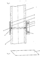
- the sealing connection system shown in FIG. 1 consists of glass tubes 1, 2 which are butted against one another for the passage of gases.
- a spacer ring 4 made of mineral material is glued between two pipe ends using an acid and temperature-resistant ceramic adhesive 3 (for example Frenzelit 1000, from Frenzelit, Bad Berneck, Federal Republic of Germany).
- an acid and temperature-resistant ceramic adhesive 3 for example Frenzelit 1000, from Frenzelit, Bad Berneck, Federal Republic of Germany.
- this spacer ring 4 can be sheathed with plastic, for example silicone.
- a bandage 5 consisting of ISOPLAN Spezial (Frenzelit, Bad Berneck, Federal Republic of Germany) is soaked in water, making this material flexible.
- This bandage 5 is then coated on one or both sides with acid and temperature-resistant ceramic adhesive 3 (for example Frenzelit 1000, from Frenzelit, Bad Berneck, Federal Republic of Germany) and placed around the pipe joint. To compensate for the diameter tolerances that occur, the bandage 5 is cut obliquely at its ends. Due to the bevelling of the bandage 5, an adequate seal occurs at the bevel edge even with different diameters.
- acid and temperature-resistant ceramic adhesive 3 for example Frenzelit 1000, from Frenzelit, Bad Berneck, Federal Republic of Germany
- FIG. 2 shows an embodiment of the bandage 5 before assembly, the bevel being 45 °.
- a clamping band 6 is tensioned around the pipe joint and the bandage 5 as a conclusion.
- the clamping band 6 remains there even after the adhesive connection has hardened and, in the case of a chimney system, the installation of the entire system in a refractory shaft or an existing chimney.
- the piping system is kept in this shaft or chimney only with spacers. The space in between is not filled. This method therefore allows quick and easy assembly.
- the clamping band 6 ensures a sufficient sealing force even in the cutting line of the bandage 5.
- the main advantage is that even when using the usual slow-curing inorganic adhesive, rapid assembly is made possible by the cohesion of the connecting components.
- the clamping band 6 is made of stainless steel, which ensures a very simple assembly and a high resistance to corrosion.
- the clamping band 6 is tensioned with the aid of clamping means, in the present embodiment with the aid of clamping screws 7a, 7b, which are fastened on the clamping band 6.
- the clamping screws 7a, 7b are tightened with a certain torque between 10 and 30 Nm, preferably 15 to 20 Nm, attracted, which leads to excellent bonding between the clamping band 6, the bandage 5 and the glass tubes 1, 2 placed next to one another.
- connection technology was chosen so that only pressure loads are exerted on the pipes to be connected during assembly, but also in later use, especially in the chimney area.
Landscapes
- Engineering & Computer Science (AREA)
- General Engineering & Computer Science (AREA)
- Mechanical Engineering (AREA)
- Rigid Pipes And Flexible Pipes (AREA)
- Clamps And Clips (AREA)
- Joining Of Glass To Other Materials (AREA)
- Flanged Joints, Insulating Joints, And Other Joints (AREA)
Abstract
Description
- Die vorliegende Erfindung betrifft ein dichtendes Verbindungssystem für ein Rohrleitungssystem, bestehend aus stumpf aneinandergesetzten Röhren mit außenliegendem Befestigungsteil zur Durchleitung von Gasen.
- Aus der DD-PS 25177 ist ein Verfahren zur Schornsteinsanierung mit Glasrohren bekannt. Dabei werden nacheinander Glasrohrabschnitte mit aufgesetzten Verbindungsmuffen durch die Öffnung des Schornsteinkopfes auf ein zuvor eingesetztes Glasrohr-T-Stück, das auf einem gemauerten Sockel aufliegt, und das eine Verbindungsmuffe aufweist, aufgesetzt, wobei die Verbindungsmuffen nach dem Aufstecken mit einer Dederon-Schnur auf den Umfang gespannt und dadurch gegen Verrutschen bei der Montage gesichert werden. Anschließend wird der Zwischenraum zwischen den Glasrohrabschnitten und der Schornsteininnenwand mit Sand verfüllt.
- Diese Verbindungsart durch aufgesetzte Muffen und Fixierschnüre hat den Nachteil, daß die dadurch entstehende Verbindung nicht ausreichend gasdicht ist. Ein weiterer Nachteil besteht darin, daß diese Verbindungen auf Dauer nicht genügend feuchtigkeitsdicht sind.
- Aufgabe der Erfindung ist es daher, ein dichtendes Verbindungssystem für Rohrleitungssysteme zu schaffen, daß die geschilderten Nachteile nicht aufweist und, im Falle von Kaminsystemen, die DIN 18 160, die Richtlinien für Querschnittsverminderung an Hausschornsteinen (Fassung September 1985), sowie die Richtlinien für die Prüfung und Benutzung von feuchtigkeitsunempfindlichen Hausschornsteinen (Fassung April 1987) erfüllt, wobei gleichzeitig die Herstellungskosten gering gehalten, und die Verbindungen selbst sehr einfach durchgeführt werden können.
- Diese Aufgabe wird erfindungsgemäß gelöst durch ein dichtendes Verbindungssystem für ein Rohrleitungssystem, bestehend aus stumpf aneinander gesetzten Röhren mit außenliegendem Befestigungsteil zur Durchleitung von Gasen, wobei ein Distanzring als Dichtung zwischen zwei Rohrenden eingeklebt wird, eine Bandage um diese Rohrenden gewickelt wird, und diese Bandage durch ein Klemmband fixiert wird, das um die Bandage sowie die Rohrenden herum mit Hilfe von Spannmitteln festgespannt wird.
- Die Erfindung wird nachfolgend anhand eines Ausführungsbeispiels in Verbindung mit den Zeichnungen näher erläutert.
- Es zeigt:
- Figur 1 einen Schnitt durch eine Ausführungsform eines erfindungsgemäßen dichtenden Verbindungssystems;
- Figur 2 eine schematische Ansicht der erfindungsgemäßen Bandage vor dem Einbau.
- Das in Figur 1 dargestellte dichtende Verbindungssytem besteht aus stumpf aneinander gesetzten Glasröhren 1, 2 zur Durchleitung von Gasen. Dabei wird zunächst ein Distanzring 4 aus mineralischem Material mit Hilfe eines säure- und temperaturbeständigen Keramik-Klebers 3 (zum Beispiel Frenzelit 1000, Firma Frenzelit, Bad Berneck, Bundesrepublik Deutschland) zwischen zwei Rohrenden eingeklebt. Dadurch wird eine gasdichte Verbindung der Glasröhren 1, 2 erreicht. Zum Feuchtigkeitsschutz bei kondensierenden Gasen kann dieser Distanzring 4 mit Kunststoff, zum Beispiel Silikon, ummantelt sein. Nun wird eine Bandage 5, bestehend aus ISOPLAN Spezial (Firma Frenzelit, Bad Berneck, Bundesrepublik Deutschland) in Wasser eingeweicht, dadurch wird dieses Material biegsam.
- Diese Bandage 5 wird dann auf einer oder beiden Seiten mit säure- und temperaturbeständigem Keramik-Kleber 3 (zum Beispiel Frenzelit 1000, Firma Frenzelit, Bad Berneck, Bundesrepublik Deutschland) bestrichen und um den Rohrstoß gelegt. Zum Ausgleich der auftretenden Durchmessertoleranzen wird die Bandage 5 an ihren Enden schräg zugeschnitten. Durch die Abschrägung der Bandage 5 tritt an der Schrägkante eine ausreichende Dichtung auch bei unterschiedlichen Durchmessern auf.
- Figur 2 zeigt eine Ausführungsform der Bandage 5 vor der Montage, wobei die Schrägung 45° beträgt.
- Zum Anpressen der Bandage 5 an das Rohr wird als Abschluß ein Klemmband 6 um den Rohrstoß und die Bandage 5 herum gespannt. Das Klemmband 6 verbleibt dort auch nach dem Aushärten der Klebeverbindung und, im Falle eines Kaminsystems, dem Einbau des gesamten Systems in einen feuerfesten Schacht beziehungsweise einen bereits vorhandenen Schornstein. Das Rohrleitungssystem wird dabei ausschließlich mit Distanzhaltern in diesem Schacht beziehungsweise dem Schornstein gehalten. Es erfolgt keine Verfüllung des Zwischenraums. Diese Methode gestattet daher eine rasche und einfache Montage. Außerdem gewährleistet das Klemmband 6 eine ausreichende Dichtkraft auch in der Schnittlinie der Bandage 5. Der Hauptvorteil besteht darin, daß auch bei Verwendung der üblichen langsam aushärtenden anorganischen Kleber eine rasche Montage durch den Zusammenhalt die verbindenden Bestandteile ermöglicht wird. Bei der vorliegenden Ausführungsform des erfindungsgemäßen dichtenden Verbindungssystems besteht das Klemmband 6 aus Edelstahl, was eine sehr einfache Montage sowie eine hohe Korrossionsbeständigkeit gewährleistet. Das Klemmband 6 wird mit Hilfe von Spannmitteln, in der vorliegenden Ausführungsform mit Hilfe von Spannschrauben 7a, 7b, die auf dem Klemmband 6 befestigt sind, gespannt. Die Spannschrauben 7a, 7b werden mit einem bestimmten Drehmoment zwischen 10 und 30 Nm, vorzugsweise 15 bis 20 Nm, angezogen, was zu einer hervorragenden Verklebung zwischen dem Klemmband 6, der Bandage 5 und den aneinandergesetzten Glasröhren 1, 2 führt.
- Dadurch ergibt sich eine dauerhafte, zugfeste Verbindung der aneinandergesetzten Rohre 1, 2, die die Bedingungen und Anforderungen der DIN 18 160, Teil 6 erfüllt, und die es ermöglicht, bis zu 1000°C heiße Gase durch das Rohrleitungssystem zu leiten. Des weiteren ist diese Verbindung sowohl feuchtigkeitsdicht als auch druckdicht entsprechend den vorne aufgeführten Richtlinien.
- Die Verbindungstechnik wurde so gewählt, damit bei Montage, aber auch im späteren Einsatz, insbesondere im Kaminbereich, auf die zu verbindenden Rohre nur Druckbelastungen ausgeübt werden.
- Die Anwendungsbreite der Erfindung beschränkt sich jedoch nicht allein auf die in dem Anwendungsbeispiel benannten Materialien.
Claims (15)
Priority Applications (1)
| Application Number | Priority Date | Filing Date | Title |
|---|---|---|---|
| AT89110587T ATE73213T1 (de) | 1988-06-22 | 1989-06-12 | Dichtende rohrverbindung und verfahren zu ihrer herstellung. |
Applications Claiming Priority (2)
| Application Number | Priority Date | Filing Date | Title |
|---|---|---|---|
| DE3821019 | 1988-06-22 | ||
| DE3821019A DE3821019A1 (de) | 1988-06-22 | 1988-06-22 | Dichtendes verbindungssystem |
Publications (2)
| Publication Number | Publication Date |
|---|---|
| EP0347701A1 true EP0347701A1 (de) | 1989-12-27 |
| EP0347701B1 EP0347701B1 (de) | 1992-03-04 |
Family
ID=6356979
Family Applications (1)
| Application Number | Title | Priority Date | Filing Date |
|---|---|---|---|
| EP89110587A Expired - Lifetime EP0347701B1 (de) | 1988-06-22 | 1989-06-12 | Dichtende Rohrverbindung und Verfahren zu ihrer Herstellung |
Country Status (3)
| Country | Link |
|---|---|
| EP (1) | EP0347701B1 (de) |
| AT (1) | ATE73213T1 (de) |
| DE (1) | DE3821019A1 (de) |
Cited By (1)
| Publication number | Priority date | Publication date | Assignee | Title |
|---|---|---|---|---|
| US5433486A (en) * | 1992-05-29 | 1995-07-18 | Schott-Rohrglas Gmbh | Pipe connection for flue-gas pipes |
Families Citing this family (6)
| Publication number | Priority date | Publication date | Assignee | Title |
|---|---|---|---|---|
| DE4000654A1 (de) * | 1990-01-11 | 1991-07-25 | Schmitz Tona Tonwerke | Verfahren zum auskleiden eines schornsteines und manschette zum verbinden der rohrabschnitte eines innenrohres hierfuer |
| DE9101553U1 (de) * | 1991-02-12 | 1991-05-16 | Vießmann, Hans, Dr., 3559 Battenberg | Rauchgasabzugsrohr |
| DE9106462U1 (de) * | 1991-02-12 | 1991-09-12 | Vießmann, Hans, Dr., 3559 Battenberg | Rauchgasabzugsrohr |
| DE4345183A1 (de) * | 1993-02-10 | 1994-09-29 | Burgmann Dichtungswerk Feodor | Anordnung zum Verbinden zweier Rohrabschnitte des keramischen Innenrohres eines Schornsteins |
| DE4332529C2 (de) * | 1993-09-24 | 1997-02-06 | Karl Heinz Vahlbrauk | Rohrleitung |
| DE10335480B3 (de) * | 2003-08-02 | 2004-10-07 | Horst Heims | Einrichtung zur Verbindung von Glasrohren |
Citations (3)
| Publication number | Priority date | Publication date | Assignee | Title |
|---|---|---|---|---|
| DE8628365U1 (de) * | 1986-10-24 | 1987-01-02 | Hartmann & Braun Ag, 6000 Frankfurt | Vorrichtung zum Abdichten der Flächen von zwei Bauteilen |
| DE3618492A1 (de) * | 1985-11-07 | 1987-05-14 | Energieversorgung Ingbetrieb | Nichtloesliche rohrverbindung fuer zylinderfoermige rohre mit selbsthaertenden abdichtstoffen |
| EP0225967A1 (de) * | 1985-12-07 | 1987-06-24 | Didier-Werke Ag | Einrichtung zum Verbinden von Teilen |
Family Cites Families (3)
| Publication number | Priority date | Publication date | Assignee | Title |
|---|---|---|---|---|
| DD25177A (de) * | ||||
| DD230056A1 (de) * | 1984-10-19 | 1985-11-20 | Energieversorgung Ingbetrieb | Nichtloesliche elastische rohrverbindung fuer zylinderfoermige rohre, insbesondere aus einem spannungsempfindlichen werkstoff mittels schrumpfmuffe |
| DE3636193A1 (de) * | 1986-10-24 | 1988-04-28 | Hartmann & Braun Ag | Vorrichtung zum abdichten der flaechen von zwei bauteilen |
-
1988
- 1988-06-22 DE DE3821019A patent/DE3821019A1/de active Granted
-
1989
- 1989-06-12 EP EP89110587A patent/EP0347701B1/de not_active Expired - Lifetime
- 1989-06-12 AT AT89110587T patent/ATE73213T1/de not_active IP Right Cessation
Patent Citations (3)
| Publication number | Priority date | Publication date | Assignee | Title |
|---|---|---|---|---|
| DE3618492A1 (de) * | 1985-11-07 | 1987-05-14 | Energieversorgung Ingbetrieb | Nichtloesliche rohrverbindung fuer zylinderfoermige rohre mit selbsthaertenden abdichtstoffen |
| EP0225967A1 (de) * | 1985-12-07 | 1987-06-24 | Didier-Werke Ag | Einrichtung zum Verbinden von Teilen |
| DE8628365U1 (de) * | 1986-10-24 | 1987-01-02 | Hartmann & Braun Ag, 6000 Frankfurt | Vorrichtung zum Abdichten der Flächen von zwei Bauteilen |
Cited By (1)
| Publication number | Priority date | Publication date | Assignee | Title |
|---|---|---|---|---|
| US5433486A (en) * | 1992-05-29 | 1995-07-18 | Schott-Rohrglas Gmbh | Pipe connection for flue-gas pipes |
Also Published As
| Publication number | Publication date |
|---|---|
| DE3821019A1 (de) | 1989-12-28 |
| EP0347701B1 (de) | 1992-03-04 |
| ATE73213T1 (de) | 1992-03-15 |
| DE3821019C2 (de) | 1991-07-18 |
Similar Documents
| Publication | Publication Date | Title |
|---|---|---|
| DE4231623A1 (de) | Zum Anschließen eines Endabschnittes eines Rohres vorgesehene Anschlußvorrichtung | |
| EP0347701B1 (de) | Dichtende Rohrverbindung und Verfahren zu ihrer Herstellung | |
| DE19882118B4 (de) | Vorrichtung und Verfahren zur Schaffung eines Einlasses in einer Einheit | |
| DE102007062855B3 (de) | Rohrhalterung, insbesondere für Rohrleitungen in Rauchgasabsorbern | |
| DE102014111691B4 (de) | Dichtungsanordnung an einer Bauwerkswand | |
| EP0390747B1 (de) | Abdichtende Verbindung von insbesondere mehrschichtigen Kunststoffrohren | |
| DE3702443A1 (de) | Vorrichtung zum abdichten von wanddurchfuehrungen | |
| EP0181945B1 (de) | Verfahren zum dichten Einbau eines rohr- oder stangenförmigen Bauteils in eine Aufnahmeöffnung eines Konstruktionskörpers | |
| DE102004061743A1 (de) | Dichtungsmaterialien und Verschlußverfahren | |
| CH656417A5 (de) | Ankerkoerper mit schutzrohr fuer ein kabel insbesondere spannkabel. | |
| DE202007018296U1 (de) | Dichtungssystem für Rohr- und Leitungsdurchführungen | |
| DE19811955A1 (de) | Verfahren zum Verlegen von Kabeln | |
| WO2004070255A1 (de) | Dämmummantelung im bereich von rohraufhängungen | |
| DE102018132949A1 (de) | Rohr aus Stahl mit einer Kunststoffummantelung als Schutzschicht gegen mechanische Beschädigungen, Herstellverfahren hierzu und Rohrleitung hieraus | |
| DE20003980U1 (de) | Verbindungsschelle für Kaminrohrelemente mit Muffenenden und Einsteckenden für Muffensteckverbindungen | |
| AT396011B (de) | Rohrverbindung, insbesondere fuer stahlbetonrohre | |
| DE102007059945B3 (de) | Anschlußvorrichtung für die Verbindung einer erdverlegten Gasleitung aus Kunststoff mit einer in einem Gebäude verlegten Stahlleitung | |
| DE10221570C1 (de) | Verbundrohr zum Auskleiden einer Rohrleitung | |
| DE60115761T2 (de) | Schlauch | |
| DE1248392B (de) | Verbindungsstueck fuer Rohrleitungen, insbesondere zu Installationszwecken | |
| DE3530588A1 (de) | Loesbare rohrkupplung zu kunststoffrohren- und armaturen | |
| DE9108303U1 (de) | Rohrförmiges Gebilde | |
| DE3137792A1 (de) | Hausanschluss-gasleitung | |
| DE202014103796U1 (de) | Dichtungsanordnung an einer Bauwerkswand | |
| DE9207960U1 (de) | Vorrichtung zum Verbinden zweier Rohrstutzen |
Legal Events
| Date | Code | Title | Description |
|---|---|---|---|
| PUAI | Public reference made under article 153(3) epc to a published international application that has entered the european phase |
Free format text: ORIGINAL CODE: 0009012 |
|
| AK | Designated contracting states |
Kind code of ref document: A1 Designated state(s): AT BE CH FR GB IT LI NL |
|
| 17P | Request for examination filed |
Effective date: 19900317 |
|
| 17Q | First examination report despatched |
Effective date: 19910220 |
|
| RAP1 | Party data changed (applicant data changed or rights of an application transferred) |
Owner name: SCHOTT-ROHRGLAS GMBH |
|
| GRAA | (expected) grant |
Free format text: ORIGINAL CODE: 0009210 |
|
| AK | Designated contracting states |
Kind code of ref document: B1 Designated state(s): AT BE CH FR GB IT LI NL |
|
| REF | Corresponds to: |
Ref document number: 73213 Country of ref document: AT Date of ref document: 19920315 Kind code of ref document: T |
|
| ET | Fr: translation filed | ||
| GBT | Gb: translation of ep patent filed (gb section 77(6)(a)/1977) | ||
| ITF | It: translation for a ep patent filed | ||
| PLBE | No opposition filed within time limit |
Free format text: ORIGINAL CODE: 0009261 |
|
| STAA | Information on the status of an ep patent application or granted ep patent |
Free format text: STATUS: NO OPPOSITION FILED WITHIN TIME LIMIT |
|
| 26N | No opposition filed | ||
| PGFP | Annual fee paid to national office [announced via postgrant information from national office to epo] |
Ref country code: GB Payment date: 19960516 Year of fee payment: 8 |
|
| PGFP | Annual fee paid to national office [announced via postgrant information from national office to epo] |
Ref country code: FR Payment date: 19960521 Year of fee payment: 8 |
|
| PGFP | Annual fee paid to national office [announced via postgrant information from national office to epo] |
Ref country code: AT Payment date: 19960523 Year of fee payment: 8 |
|
| PGFP | Annual fee paid to national office [announced via postgrant information from national office to epo] |
Ref country code: CH Payment date: 19960524 Year of fee payment: 8 Ref country code: BE Payment date: 19960524 Year of fee payment: 8 |
|
| PGFP | Annual fee paid to national office [announced via postgrant information from national office to epo] |
Ref country code: NL Payment date: 19960529 Year of fee payment: 8 |
|
| PG25 | Lapsed in a contracting state [announced via postgrant information from national office to epo] |
Ref country code: GB Free format text: LAPSE BECAUSE OF NON-PAYMENT OF DUE FEES Effective date: 19970612 Ref country code: AT Effective date: 19970612 |
|
| PG25 | Lapsed in a contracting state [announced via postgrant information from national office to epo] |
Ref country code: LI Free format text: LAPSE BECAUSE OF NON-PAYMENT OF DUE FEES Effective date: 19970630 Ref country code: CH Free format text: LAPSE BECAUSE OF NON-PAYMENT OF DUE FEES Effective date: 19970630 Ref country code: BE Effective date: 19970630 |
|
| BERE | Be: lapsed |
Owner name: SCHOTT-ROHRGLAS G.M.B.H. Effective date: 19970630 |
|
| PG25 | Lapsed in a contracting state [announced via postgrant information from national office to epo] |
Ref country code: NL Effective date: 19980101 |
|
| GBPC | Gb: european patent ceased through non-payment of renewal fee |
Effective date: 19970612 |
|
| REG | Reference to a national code |
Ref country code: CH Ref legal event code: PL |
|
| PG25 | Lapsed in a contracting state [announced via postgrant information from national office to epo] |
Ref country code: FR Free format text: LAPSE BECAUSE OF NON-PAYMENT OF DUE FEES Effective date: 19980227 |
|
| NLV4 | Nl: lapsed or anulled due to non-payment of the annual fee |
Effective date: 19980101 |
|
| REG | Reference to a national code |
Ref country code: FR Ref legal event code: ST |
|
| REG | Reference to a national code |
Ref country code: FR Ref legal event code: ST |
|
| PG25 | Lapsed in a contracting state [announced via postgrant information from national office to epo] |
Ref country code: IT Free format text: LAPSE BECAUSE OF NON-PAYMENT OF DUE FEES;WARNING: LAPSES OF ITALIAN PATENTS WITH EFFECTIVE DATE BEFORE 2007 MAY HAVE OCCURRED AT ANY TIME BEFORE 2007. THE CORRECT EFFECTIVE DATE MAY BE DIFFERENT FROM THE ONE RECORDED. Effective date: 20050612 |