EP0347652B1 - Rückenlehne für Sitz- und Liegeplatten - Google Patents
Rückenlehne für Sitz- und Liegeplatten Download PDFInfo
- Publication number
- EP0347652B1 EP0347652B1 EP89110327A EP89110327A EP0347652B1 EP 0347652 B1 EP0347652 B1 EP 0347652B1 EP 89110327 A EP89110327 A EP 89110327A EP 89110327 A EP89110327 A EP 89110327A EP 0347652 B1 EP0347652 B1 EP 0347652B1
- Authority
- EP
- European Patent Office
- Prior art keywords
- plate
- hinge
- backrest
- latching
- sitting
- Prior art date
- Legal status (The legal status is an assumption and is not a legal conclusion. Google has not performed a legal analysis and makes no representation as to the accuracy of the status listed.)
- Expired - Lifetime
Links
- XLYOFNOQVPJJNP-UHFFFAOYSA-N water Substances O XLYOFNOQVPJJNP-UHFFFAOYSA-N 0.000 claims description 4
- 230000000295 complement effect Effects 0.000 claims 1
- 238000005406 washing Methods 0.000 description 3
- 230000004323 axial length Effects 0.000 description 1
- 238000003287 bathing Methods 0.000 description 1
- 230000006835 compression Effects 0.000 description 1
- 238000007906 compression Methods 0.000 description 1
- 230000006378 damage Effects 0.000 description 1
- 238000012423 maintenance Methods 0.000 description 1
- 239000002991 molded plastic Substances 0.000 description 1
Images

Classifications
-
- A—HUMAN NECESSITIES
- A61—MEDICAL OR VETERINARY SCIENCE; HYGIENE
- A61G—TRANSPORT, PERSONAL CONVEYANCES, OR ACCOMMODATION SPECIALLY ADAPTED FOR PATIENTS OR DISABLED PERSONS; OPERATING TABLES OR CHAIRS; CHAIRS FOR DENTISTRY; FUNERAL DEVICES
- A61G7/00—Beds specially adapted for nursing; Devices for lifting patients or disabled persons
- A61G7/10—Devices for lifting patients or disabled persons, e.g. special adaptations of hoists thereto
- A61G7/1001—Devices for lifting patients or disabled persons, e.g. special adaptations of hoists thereto specially adapted for specific applications
- A61G7/1003—Devices for lifting patients or disabled persons, e.g. special adaptations of hoists thereto specially adapted for specific applications mounted on or in combination with a bath-tub
-
- A—HUMAN NECESSITIES
- A61—MEDICAL OR VETERINARY SCIENCE; HYGIENE
- A61G—TRANSPORT, PERSONAL CONVEYANCES, OR ACCOMMODATION SPECIALLY ADAPTED FOR PATIENTS OR DISABLED PERSONS; OPERATING TABLES OR CHAIRS; CHAIRS FOR DENTISTRY; FUNERAL DEVICES
- A61G7/00—Beds specially adapted for nursing; Devices for lifting patients or disabled persons
- A61G7/10—Devices for lifting patients or disabled persons, e.g. special adaptations of hoists thereto
- A61G7/1013—Lifting of patients by
- A61G7/1019—Vertical extending columns or mechanisms
-
- A—HUMAN NECESSITIES
- A61—MEDICAL OR VETERINARY SCIENCE; HYGIENE
- A61G—TRANSPORT, PERSONAL CONVEYANCES, OR ACCOMMODATION SPECIALLY ADAPTED FOR PATIENTS OR DISABLED PERSONS; OPERATING TABLES OR CHAIRS; CHAIRS FOR DENTISTRY; FUNERAL DEVICES
- A61G7/00—Beds specially adapted for nursing; Devices for lifting patients or disabled persons
- A61G7/10—Devices for lifting patients or disabled persons, e.g. special adaptations of hoists thereto
- A61G7/1049—Attachment, suspending or supporting means for patients
- A61G7/1059—Seats
-
- A—HUMAN NECESSITIES
- A61—MEDICAL OR VETERINARY SCIENCE; HYGIENE
- A61G—TRANSPORT, PERSONAL CONVEYANCES, OR ACCOMMODATION SPECIALLY ADAPTED FOR PATIENTS OR DISABLED PERSONS; OPERATING TABLES OR CHAIRS; CHAIRS FOR DENTISTRY; FUNERAL DEVICES
- A61G7/00—Beds specially adapted for nursing; Devices for lifting patients or disabled persons
- A61G7/10—Devices for lifting patients or disabled persons, e.g. special adaptations of hoists thereto
- A61G7/1073—Parts, details or accessories
- A61G7/1082—Rests specially adapted for
- A61G7/1088—Back
-
- A—HUMAN NECESSITIES
- A61—MEDICAL OR VETERINARY SCIENCE; HYGIENE
- A61G—TRANSPORT, PERSONAL CONVEYANCES, OR ACCOMMODATION SPECIALLY ADAPTED FOR PATIENTS OR DISABLED PERSONS; OPERATING TABLES OR CHAIRS; CHAIRS FOR DENTISTRY; FUNERAL DEVICES
- A61G7/00—Beds specially adapted for nursing; Devices for lifting patients or disabled persons
- A61G7/10—Devices for lifting patients or disabled persons, e.g. special adaptations of hoists thereto
- A61G7/1013—Lifting of patients by
- A61G7/1021—Inflatable cushions
Definitions
- the invention relates to a bathtub insert for the disabled with the features of the preamble of claim 1.
- Such a bathtub insert is known from DE-C-35 08 056 (EP-A-0 193 730).
- the backrest consists of a narrow plate on which arms which extend downwards and extend through holes in the seat plate and are supported in front of the holes on the underside of the seat plate.
- the backrest can thus be detached from the seat plate. In its functional position, it has a predetermined, constant inclination. Disabled people often cannot control their movements. You can tilt the upper body to the side on the seat plate. This can lead to injuries, especially when lifting and lowering the seat plate.
- the inclination of the backrest also poses some problems in practice.
- the well-known bathtub insert has a relatively steep backrest, which enables the staff to keep the upper body of the handicapped upright for washing the back, but the steep position carries the risk that unsupervised patients can fall forward.
- a flatter position of the backrest would be safer for unattended bathing and more comfortable for the patient.
- the object of the invention is to design the bath insert of the type mentioned in such a way that the backrest is designed and arranged in such a way that the disabled patient is provided with greater security for the maintenance of his chosen sitting-lying position on the seat or lying-down plate without hindering the activity of the personnel in washing the patient.
- the swiveling side plates on the backrest provide the patient with lateral support without having to hold on to the tub edges. Thanks to the fine adjustment of the opening angle of the side panels, an individual adjustment to the patient's upper body width can be achieved, so that the bathtub insert is suitable for children as well as for diverent adults. Since the disabled come from the side onto the seat plate and also leave it to the side, the side plates can be pivoted back at least into the plane of the backrest, but preferably backwards up to the back of the backrest. In this position, the disabled can also be washed by the staff without disturbing the side panels.
- the swiveling mounting of the backrest itself allows the disabled person to search for an inclined position suitable for him, in which he can also bathe in a stable position unattended.
- the backrest can easily be swiveled into a steep position by the staff to the upper body of the disabled for that subsequent washing and straightening up for getting in and out of the bath.
- fine-stage swivel angle adjusting devices are integrated in conventional hinges. This has the advantage of particularly simple handling without having to operate any actuating elements.
- the side plates and / or the backrest need only be shifted slightly in the direction of their respective pivot axis in order to release the latching and to be able to pivot the respective plate freely.
- a slight lifting is sufficient for the side plates to be able to pivot them freely both inwards and outwards.
- the weight of the side plates is in itself sufficient to automatically snap them back into the selected angular position.
- a built-in compression spring is preferably used, which prestresses the locking hinge in its locking position.
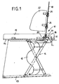
- a bathtub insert 10 has a lifting device 12 in the form of a hose which can be filled with pressurized water and a guide device 14 in the form of at least one pair of scissors frames. Lifting device 12 and guide device 14 are arranged between a base plate 13 and a seat plate 16.
- a control device 15 in the form of a manually operable valve allows the lifting device 12 to be connected to a pressurized water line, the lifting device to be shut off and emptied.
- a backrest 18 is arranged so as to be detachable, which has two angled arms 20 which protrude through openings in the seat plate 16 and lie against the underside of the seat plate 16 (FIG. 2).
- Side plates 22 are located on the two upright longitudinal edges of the backrest 18 by means of hinge arrangements 24 pivotally mounted.
- the backrest can be designed trapezoidal, so that the two side edges diverge upwards.
- the pivot axes of the side plates 22 run at or at a short distance approximately parallel to the backrest.
- the backrest 18 itself is also pivotally mounted on a mounting plate 26 about a transverse axis by means of a hinge arrangement 24.
- the mounting plate 26 is supported on the seat plate 16 and supports the arms 20.
- the pivot axis of the backrest 18 in the exemplary embodiment lies slightly above the seat plate 16, but can also run in the plane of the seat plate 16 if corresponding recesses in the hinge arrangement 24 Seat plate 16 are provided.
- FIG. 5 differs from the embodiment according to FIG. 1 characterized in that the seat plate 16 is extended and thus designed as a bed plate, that the guide device 14 comprises two pairs of heavy frames and the lifting device 12 comprises two pressurized water surfaces and that the hinge arrangement 24 for adjusting the inclination of the backrest 18 is missing.
- the hinge arrangement 24 comprises at least one hinge which has two hinge plates 28, each with a rolled-in bush 30, which protrudes in one piece from the respective hinge plate 28 and only in one half of the hinge plate is arranged.
- the two bushes 30 of the identically designed two hinge plates 28 are penetrated by a hinge pin 32.
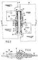
- FIGS. 3 and 4 show an embodiment of a hinge arrangement 24, in which a locking toothing is arranged on two adjacent, interlocking circumferential surfaces.
- the bushing 30 (2nd bushing) of the one hinge plate 28 has an axial hollow cylindrical projection (collar) 50, the outer circumference of which is provided with a large number of closely spaced axial webs 52 (axial ribs).
- the other bushing 30 (1st bushing) has a bore section 54, on the inner circumference of which a plurality of closely adjacent axial grooves 56 are formed, which extend over the axial length of the bore section 54. In the latched position, the projection 50 dips into the bore section 54 and the interlocking axial webs and axial grooves provide a positive rotation lock.
- the hinge pin 32 in the exemplary embodiment according to FIG. 3 consists of a round rod, which has ring grooves at both ends, in which locking rings 60, 62 are inserted.
- the locking ring 62 is supported on an annular shoulder of an end recess 64 of the first bush 30, while the locking ring 60 forms the abutment for the spring 44, which is received here in an enlarged bore 58 of the displaceable second bush 30 and is located on the inner Ring shoulder of this bore section 58 is supported.
- FIG. 3 illustrates the hinge in the disengaged position.
- the side plate 22 must be held by hand when pivoting.
- the spring 44 automatically locks the hinge.
- Each hinge plate 28 is designed as a one-piece molded plastic part.
- the hinge plate 28 has two fastening tabs 28a, 28b between which a gap for inserting the side plate 22 or the backrest 18 is formed.
Landscapes
- Health & Medical Sciences (AREA)
- Veterinary Medicine (AREA)
- Life Sciences & Earth Sciences (AREA)
- Animal Behavior & Ethology (AREA)
- General Health & Medical Sciences (AREA)
- Public Health (AREA)
- Nursing (AREA)
- Devices For Medical Bathing And Washing (AREA)
- Residential Or Office Buildings (AREA)
- Bathtubs, Showers, And Their Attachments (AREA)
- Chairs For Special Purposes, Such As Reclining Chairs (AREA)
- Percussion Or Vibration Massage (AREA)
- Special Chairs (AREA)
- Chairs Characterized By Structure (AREA)
- Water Treatment By Sorption (AREA)
- Treatment Of Water By Ion Exchange (AREA)
- Prostheses (AREA)
- Glass Compositions (AREA)
- Laminated Bodies (AREA)
- Chair Legs, Seat Parts, And Backrests (AREA)
- Finger-Pressure Massage (AREA)
- Reverberation, Karaoke And Other Acoustics (AREA)
- Adornments (AREA)
Description
- Die Erfindung betrifft einen Badewanneneinsatz für Behinderte mit den Merkmalen des Oberbegriffes von Patentanspruch 1.
- Ein derartiger Badewanneneinsatz ist aus der DE-C-35 08 056 (EP-A-0 193 730) bekannt. Die Rückenlehne besteht aus einer schmalen Platte, an der sich nach unten erstreckende und durch Löcher in der Sitzplatte hindurch erstreckende und sich vor den Löchern an der Unterseite der Sitzplatte abstützende Arme befestigt sind. Die Rückenlehne ist damit aus der Sitzplatte aushängbar. Sie hat in ihrer Funktionsstellung eine vorgegebene unveränderliche Neigung. Behinderte können ihre Bewegungen häufig nicht kontrollieren. Sie können auf der Sitzplatte mit ihrem Oberkörper zur Seite kippen. Insbesondere beim Heben und Senken der Sitzplatte kann dies zu Verletzungen führen. Auch die Neigung der Rückenlehne wirft einige Probleme in der Praxis auf. Der bekannte Badewanneneinsatz hat eine relativ steile Rückenlehne, die es dem Personal ermöglicht, den Oberkörper des Behinderten zum Waschen des Rückens aufrecht zu stellen, jedoch birgt die steile Stellung die Gefahr, daß unbeaufsichtigte Patienten nach vorn fallen können. Für das unbeaufsichtigte Baden wäre eine flachere Stellung der Rückenlehne sicherer und für den Patienten bequemer.
- Aufgabe der Erfindung ist es, den Badewanneneinsatz der eingangs genannten Art so auszubilden, daß die Rückenlehne so ausgebildet und angeordnet wird, daß dem behinderten Patienten eine größere Sicherheit für die Einhaltung seiner gewählten Sitz-Liegestellung auf der Sitz- oder Liegeplatte vermittelt wird, ohne die Tätigkeit des Personals zu behindern, den Patienten zu waschen.
- Diese Aufgabe wird bei einem Badewanneneinsatz mit den Merkmalen des Oberbegriffs von Patentanspruch 1 durch dessen kennzeichnende Merkmale gelöst. Die schwenkbaren Seitenplatten an der Rückenlehne vermitteln dem Patienten einen seitlichen Halt, ohne daß dieser sich an den Wannenrändern festhalten müßte. Dank der feinstufigen Einstellung des Öffnungswinkels der Seitenplatten, läßt sich eine individuelle Anpassung an die Oberkörperbreite des Patienten erreichen, sodaß der Badewanneneinsatzz gleich gut für Kinder, wie auch für korpulente Erwachsene geeignet ist. Da die Behinderten von der Seite her auf die Sitzplatte gelangen und diese auch zur Seite hin verlassen, sind die Seitenplatten mindestens in die Ebene der Rückenlehne, vorzugsweise aber nach hinten bis an die Rückseite der Rückenlehne zurückschwenkbar. In dieser Stellung kann der Behinderte auch vom Personal gewaschen werden, ohne daß die Seitenplatten stören. Die schwenkbare Lagerung der Rückenlehne selbst gestattet es, dem Behinderten eine für ihn geeignete Schräglage zu suchen, in der er auch unbeaufsichtigt lagestabil baden kann. Die Rückenlehne kann vom Personal leicht in eine Steilstellung verschwenkt werden, um den Oberkörper des Behinderten für das anschließende Waschen und für das Ein-und Aussteigen aus der Badewanne aufzurichten.
- Bei den erfindungsgemäßen Rastscharnieranordnungen sind feinstufige Schwenkwinkel-Einstelleinrichtungen in herkömmliche Scharniere integriert. Dies bringt den Vorteil einer besonders einfachen Handhabung,ohne irgendwelche Betätigungselemente bedienen zu müssen. Die Seitenplatten und/oder die Rückenlehne brauchen lediglich in Richtung ihrer jeweiligen Schwenkachse geringfügig verschoben zu werden, um die Verrastung zu lösen und die jeweilige Platte frei verschwenken zu können. Für die Seitenplatten genügt ein geringes Anheben, um sie frei sowohl einwärts als auch auswärts verschwenken zu können. Das Gewicht der Seitenplatten reicht ansich schon aus, um sie selbsttätig wieder in der gewählten Winkelstellung einrasten zu lassen. Vorzugsweise wird eine eingebaute Druckfeder verwendet, die das Rastscharnier in seine Raststellung vorspannt.
- Die Erfindung wird nachstehend anhand der Zeichnung näher erläutert.
- Es zeigt
- FIG. 1 eine teilweise geschnittene Seitenansicht eines Badewanneneinsatzes,
- FIG. 2 eine Draufsicht auf den Badewanneneinsatz mit im Schnitt dargestellter Rücklehnenanordnung,
- FIG. 3 eine Schnittansicht durch eine Ausführungsform einer Scharnieranordnung,
- FIG. 4 einen Querschnitt längs der Linie 5-5 der FIG. 3 und
- FIG. 5 eine Seitenansicht eines Badewanneneinsatzes mit Liegeplatte und abgeänderter Rückenlehne.
- Ein Badewanneneinsatz 10 weist eine Hubeinrichtung 12 in Form eines mit Druckwasser füllbaren Schlauches und eine Führungseinrichtung 14 in Form mindestens eines Scherenrahmenpaars auf. Hubeinrichtung 12 und Führungseinrichtung 14 sind zwischen einer Bodenplatte 13 und einer Sitzplatte 16 angeordnet. Eine Steuereinrichtung 15 in Form eines manuell betätigbaren Ventils erlaubt den Anschluß der Hubeinrichtung 12 an eine Druckwasserleitung, das Absperren der Hubeinrichtung und seine Entleerung.
- Auf der Sitzplatte 16 ist eine Rückenlehne 18 aushängbar angeordnet, die zwei gewinkelte Arme 20 aufweist, die durch Öffnungen in der Sitzplatte 16 hindurchragen und sich an der Unterseite der Sitzplatte 16 anlegen (Fig.2). An den beiden aufrechten Längsrändern der Rückenlehne 18 sind Seitenplatten 22 mittels Scharnieranordnungen 24 schwenkbar gelagert. Die Rückenlehne kann trapezförmig gestaltet ein, sodaß die beiden Seitenränder nach oben divergieren. Die Schwenkachsen der Seitenplatten 22 verlaufen in oder in geringem Abstand etwa parallel zur Rückenlehne. Die Rückenlehne 18 selbst ist ebenfalls mittels einer Scharnieranordnung 24 an einer Befestigungsplatte 26 um eine Querachse schwenkbar gelagert. Die Befestigungsplatte 26 stützt sich auf der Sitzplatte 16 ab und trägt die Arme 20. Die Schwenkachse der Rückenlehne 18 liegt im Ausführungsbeispiel geringfügig oberhalb der Sitzplatte 16, kann jedoch auch in der Ebene der Sitzplatte 16 verlaufen, wenn für die Scharnieranordnung 24 entsprechende Ausnehmungen in der Sitzplatte 16 vorgesehen sind.
- FIG. 5 unterscheidet sich von der Ausführung gemäß FIG. 1 dadurch, daß die Sitzplatte 16 verlängert und somit als Liegeplatte ausgebildet ist, daß die Führungseinrichtung 14 zwei Schwerenrahmenpaare und die Hubeinrichtung 12 zwei Druckwasserschläche umfaßt und daß die Scharnieranordnung 24 zum Verstellen der Neigung der Rückenlehne 18 fehlt.
- Die Scharnieranordnung 24 umfaßt mindestens ein Scharnier, das zwei Scharnierplatten 28 mit je einer eingerollten Buchse 30 aufweist, die einstückig von der jeweiligen Scharnierplatte 28 vorsteht und nur in einer Hälfte der Scharnier platte angeordnet ist. Die beiden Buchsen 30 der identisch ausgebildeten beiden Scharnierplatten 28 werden von einem Scharnierbolzen 32 durchsetzt.
- Die Figuren 3 und 4 zeigen eine Ausführungsform einer Scharnieranordnung 24, bei der eine Rastverzahnung an zwei benachbarten ineinandergreifenden Umfangsflächen angeordnet sind. Die Buchse 30 (2.Buchse) der einen Scharnierplatte 28 weist einen axialen hohlzylindrischen Vorsprung (Bund) 50 auf, dessen Außenumfang mit einer Vielzahl eng beeinanderliegender Axialstege 52 (Axialrippen) versehen ist. Die andere Buchse 30 (1.Buchse) hat einen Bohrungsabschnitt 54 , an dessen Innenumfang eine Vielzahl eng benachbarter Axialnuten 56 ausgebildet ist, die sich über die axiale Länge des Bohrungsabschnittes 54 erstrecken. In der Raststellung taucht der Vorsprung 50 in den Bohrungsabschnitt 54 ein und die ineinandergreifenden Axialstege und Axialnuten ergeben eine formschlüssige Drehsicherung.
- Der Scharnierbolzen 32 im Ausführungsbeispiel gemäß FIG .3 besteht aus einer runden Stange, die an beiden Enden Ringnuten aufweist, in welche Sperringe 60, 62 eingesetzt sind. Der Sperring 62 stützt sich an einer Ringschulter einer Endausnehmung 64 der 1.Buchse 30 ab, während der Sperring 60 das Widerlager für die Feder 44 bildet, die hier in einer erweiterten Bohrung 58 der verschiebbaren 2.Buchse 30 aufgenommen ist und sich an der inneren Ringschulter dieses Bohrungsabschnittes 58 abstützt.
- FIG. 3 veranschaulicht das Scharnier in der ausgerasteten Stellung. In dieser muß die Seitenplatte 22 von Hand beim Verschwenken gehalten werden. Beim Loslassen sorgt die Feder 44 für eine automatische Verrastung des Scharniers.
- Jede Scharnierplatte 28 ist als einstückiges Kunststoffformteil ausgebildet. Die Scharnierplatte 28 hat zwei Befestigungslaschen 28a, 28b zwischen denen ein Spalt zum Einstecken der Seitenplatte 22 bzw. der Rückenlehne 18 gebildet ist.
Claims (2)
Priority Applications (1)
| Application Number | Priority Date | Filing Date | Title |
|---|---|---|---|
| AT89110327T ATE74743T1 (de) | 1988-06-23 | 1989-06-08 | Rueckenlehne fuer sitz- und liegeplatten. |
Applications Claiming Priority (2)
| Application Number | Priority Date | Filing Date | Title |
|---|---|---|---|
| DE3821192 | 1988-06-23 | ||
| DE3821192A DE3821192A1 (de) | 1988-06-23 | 1988-06-23 | Rueckenlehne fuer sitz- oder liegeplatten |
Publications (3)
| Publication Number | Publication Date |
|---|---|
| EP0347652A2 EP0347652A2 (de) | 1989-12-27 |
| EP0347652A3 EP0347652A3 (en) | 1990-07-18 |
| EP0347652B1 true EP0347652B1 (de) | 1992-04-15 |
Family
ID=6357075
Family Applications (1)
| Application Number | Title | Priority Date | Filing Date |
|---|---|---|---|
| EP89110327A Expired - Lifetime EP0347652B1 (de) | 1988-06-23 | 1989-06-08 | Rückenlehne für Sitz- und Liegeplatten |
Country Status (13)
| Country | Link |
|---|---|
| US (1) | US4932087A (de) |
| EP (1) | EP0347652B1 (de) |
| JP (1) | JPH0241160A (de) |
| AT (1) | ATE74743T1 (de) |
| AU (1) | AU608989B2 (de) |
| CA (1) | CA1319463C (de) |
| DE (2) | DE3821192A1 (de) |
| DK (1) | DK167647B1 (de) |
| ES (1) | ES2030560T3 (de) |
| FI (1) | FI90308C (de) |
| GR (1) | GR3004613T3 (de) |
| NO (1) | NO892606L (de) |
| SA (1) | SA89100013B1 (de) |
Families Citing this family (21)
| Publication number | Priority date | Publication date | Assignee | Title |
|---|---|---|---|---|
| DE59208090D1 (de) * | 1991-06-24 | 1997-04-10 | Roland Schwarz | Verfahren zum Steuern einer Hubeinrichtung und Hubeinrichtung für bewegungsbehinderte Menschen |
| DE4130323C2 (de) * | 1991-09-12 | 2000-03-23 | Schmidt & Lenhardt Gmbh & Co | Badewanneneinsatz für Behinderte |
| WO1993009748A1 (en) * | 1991-11-15 | 1993-05-27 | John Clark Mustarde | Bath lift |
| US5797149A (en) * | 1991-11-15 | 1998-08-25 | Mustarde; John Clarke | Bath lift |
| DE4222939C1 (de) * | 1992-07-11 | 1993-07-22 | Meyra Wilhelm Meyer Gmbh & Co Kg, 4925 Kalletal, De | |
| ES2070646T3 (es) * | 1993-01-15 | 1995-06-01 | Schmidt & Lenhardt Gmbh & Co | Tubo flexible de elevacion con extremos cerrados mediante regletas de apriete. |
| EP0691115B1 (de) * | 1993-03-05 | 1996-04-24 | Schmidt & Lenhardt GmbH & Co. oHG | In Badewannen einsetzbarer Lifter |
| DE59304901D1 (de) * | 1993-03-05 | 1997-02-06 | Schmidt & Lenhardt Gmbh & Co | In eine Badewanne einsetzbarer Lifter |
| DE4437513C2 (de) * | 1994-10-20 | 1997-07-17 | Walter Gobbers | Vorrichtung zum Einsetzen in eine Badewanne oder dergleichen als Ein- und Ausstiegshilfe |
| DE59600230D1 (de) * | 1996-03-14 | 1998-07-02 | Schmidt & Lenhardt Gmbh & Co | Rückenstütze für Badelifter |
| DE19720963B4 (de) * | 1996-05-22 | 2007-02-22 | A & S Bäder GmbH | Rückenstütze für Badewannen |
| US6240577B1 (en) | 1999-10-18 | 2001-06-05 | Ricky L. Worthy | Method and apparatus for a bathtub mountable chair |
| JP2002119569A (ja) * | 2000-10-18 | 2002-04-23 | Og Giken Co Ltd | 改良式介護装置 |
| USD452056S1 (en) | 2001-01-08 | 2001-12-11 | Elizabeth Rosania | Seat for use in a bathtub |
| US6415459B1 (en) | 2001-04-24 | 2002-07-09 | Robert E. Sevier | Tub for physically handicapped persons |
| US7270861B2 (en) * | 2002-12-20 | 2007-09-18 | The Procter & Gamble Company | Laminated structurally elastic-like film web substrate |
| JP5572503B2 (ja) * | 2010-09-27 | 2014-08-13 | 酒井医療株式会社 | 入浴用車椅子 |
| EP3257490A1 (de) | 2016-06-17 | 2017-12-20 | Sunrise Medical GmbH | Seitenhalter für eine haltungssitzstütze |
| US10849821B2 (en) | 2019-03-27 | 2020-12-01 | Paula Jo Hennessy | Hydrotherapy soaking chair and method for use |
| US11654066B2 (en) * | 2019-06-13 | 2023-05-23 | Drive Medical Gmbh & Co. Kg | Bathtub lift |
| RU2711156C1 (ru) * | 2019-08-07 | 2020-01-15 | Владимир Викторович Михайлов | Сиденье для унитаза |
Family Cites Families (23)
| Publication number | Priority date | Publication date | Assignee | Title |
|---|---|---|---|---|
| US3123400A (en) * | 1964-03-03 | Invalid s chair | ||
| DE234930C (de) * | 1900-01-01 | |||
| US2635679A (en) * | 1950-01-11 | 1953-04-21 | Joseph E Mcdonald | Folding boat seat with adjustable back rest |
| US2779949A (en) * | 1952-06-27 | 1957-02-05 | Clarence C Crispen | Hydraulic lift for bath tubs |
| DE1455806A1 (de) * | 1964-03-11 | 1969-05-29 | Keiper Recaro Gmbh Co | Gelenkbeschlag fuer Sitze,insbesondere Kraftfahrzeugsitze |
| DE1934785A1 (de) * | 1969-07-09 | 1971-01-28 | Geyr Utila Geraetebau | Vorrichtung zur Erleichterung des Ein- und Ausstiegs von koerperbehinderten und altersschwachen Personen in eine bzw. aus einer Badewanne |
| GB1323861A (en) * | 1971-01-07 | 1973-07-18 | Bath Inst Of Medical Eng | Arm rest for invalid chair cularly suitable for flooring |
| GB1496583A (en) * | 1975-01-21 | 1977-12-30 | James D | Sanitary and commode chairs |
| GB2014446B (en) * | 1977-12-22 | 1983-01-19 | Garman D E T | Bathing supports |
| FR2427818A1 (fr) * | 1978-06-08 | 1980-01-04 | Rioufrays Jean | Chaise de mise a l'eau pour handicapes physiques |
| JPS5635388A (en) * | 1979-08-30 | 1981-04-08 | Nitto Electric Ind Co | Selfftemperature controlled heating element |
| DE3002149A1 (de) * | 1980-01-22 | 1981-07-23 | Wilhelm 8830 Treuchtlingen Hüttinger | Wasserhydraulische hebeeinrichtung fuer bad |
| EP0073757A4 (de) * | 1981-03-09 | 1984-04-24 | Harry H Herman Jr | Verbesserte hilfskissenanordnung für badewannen. |
| GB2117236B (en) * | 1982-02-23 | 1986-02-19 | Mountway Limited | Lifting devices for use with baths etc |
| GB2120933B (en) * | 1982-05-28 | 1985-09-11 | Pennington Richards Cyril Mont | Apparatus for helping a person to get in or out of a bath |
| CH659575A5 (de) * | 1983-03-03 | 1987-02-13 | Kurt Brandenberger | Tragvorrichtung fuer eine heb- und drehbare sitz- oder liegeanordnung. |
| DE3324294A1 (de) * | 1983-07-06 | 1985-01-24 | Peter 7989 Argenbühl Schmidt | Badewanneneinsatz fuer behinderte |
| DE3337536A1 (de) * | 1983-10-14 | 1985-05-02 | Wolfgang 7970 Leutkirch Dentler | Hubvorrichtung fuer einen badewanneneinsatz |
| US4624019A (en) * | 1984-05-21 | 1986-11-25 | Pennington Richards Cyril M | Apparatus for helping a person to get in or out of a bath |
| GB8432242D0 (en) * | 1984-12-20 | 1985-01-30 | Broadstand Ltd | Chair |
| DE3546578C2 (en) * | 1985-03-07 | 1988-10-06 | Peter 7989 Eisenharz De Schmidt | Bath tub insert |
| DE3704628C1 (en) * | 1987-02-13 | 1988-09-22 | Ulrich Kleinhans | Displacement system for the disabled |
| US4768239A (en) * | 1987-09-28 | 1988-09-06 | Pauley William E | Bath lift device |
-
1988
- 1988-06-23 DE DE3821192A patent/DE3821192A1/de not_active Withdrawn
-
1989
- 1989-06-08 EP EP89110327A patent/EP0347652B1/de not_active Expired - Lifetime
- 1989-06-08 DE DE8989110327T patent/DE58901144D1/de not_active Expired - Lifetime
- 1989-06-08 ES ES198989110327T patent/ES2030560T3/es not_active Expired - Lifetime
- 1989-06-08 AT AT89110327T patent/ATE74743T1/de not_active IP Right Cessation
- 1989-06-13 FI FI892875A patent/FI90308C/fi not_active IP Right Cessation
- 1989-06-20 JP JP1156957A patent/JPH0241160A/ja active Pending
- 1989-06-21 CA CA000603526A patent/CA1319463C/en not_active Expired - Fee Related
- 1989-06-21 US US07/369,339 patent/US4932087A/en not_active Expired - Fee Related
- 1989-06-22 DK DK309489A patent/DK167647B1/da not_active IP Right Cessation
- 1989-06-22 NO NO89892606A patent/NO892606L/no unknown
- 1989-06-23 AU AU37003/89A patent/AU608989B2/en not_active Ceased
- 1989-09-19 SA SA89100013A patent/SA89100013B1/ar unknown
-
1992
- 1992-05-18 GR GR920400937T patent/GR3004613T3/el unknown
Also Published As
| Publication number | Publication date |
|---|---|
| ES2030560T3 (es) | 1992-11-01 |
| FI90308C (fi) | 1994-01-25 |
| SA89100013B1 (ar) | 2001-01-01 |
| DK167647B1 (da) | 1993-12-06 |
| CA1319463C (en) | 1993-06-29 |
| FI892875L (fi) | 1989-12-24 |
| EP0347652A2 (de) | 1989-12-27 |
| NO892606D0 (no) | 1989-06-22 |
| FI90308B (fi) | 1993-10-15 |
| FI892875A0 (fi) | 1989-06-13 |
| US4932087A (en) | 1990-06-12 |
| GR3004613T3 (de) | 1993-04-28 |
| DE58901144D1 (de) | 1992-05-21 |
| DK309489A (da) | 1989-12-24 |
| DK309489D0 (da) | 1989-06-22 |
| EP0347652A3 (en) | 1990-07-18 |
| JPH0241160A (ja) | 1990-02-09 |
| DE3821192A1 (de) | 1989-12-28 |
| NO892606L (no) | 1989-12-27 |
| AU608989B2 (en) | 1991-04-18 |
| AU3700389A (en) | 1990-01-04 |
| ATE74743T1 (de) | 1992-05-15 |
Similar Documents
| Publication | Publication Date | Title |
|---|---|---|
| EP0347652B1 (de) | Rückenlehne für Sitz- und Liegeplatten | |
| DE3879714T2 (de) | Ergonomischer stuhl mit einem verstellbaren sitz. | |
| EP0617947A1 (de) | Drehteller für Behinderte | |
| DE68918465T2 (de) | Faltbarer rollstuhl. | |
| DE2601021A1 (de) | Verbesserungen bei nachtstuehlen | |
| DE2653326A1 (de) | Hebevorrichtung fuer badezwecke | |
| DE2210492B2 (de) | Krankenfahrstuhl | |
| DE202020101493U1 (de) | Winkelverstellanordnung eines Toiletten- und Duschstuhls | |
| DE8806924U1 (de) | Sitzmöbel | |
| DE4432501A1 (de) | Sitzeinheit | |
| DE2738567C3 (de) | Orthopädisches Gerät für die Wirbelsäulenstreckung bei einem sitzenden, stehenden oder gehenden Patienten | |
| EP0121899A2 (de) | Fahrzeugsitz | |
| EP0578947A1 (de) | Badewannenlift | |
| DE3742465C2 (de) | ||
| AT395529B (de) | Behandlungsliege, insbesondere massageliege | |
| DE4442039A1 (de) | Vorrichtung zum Hochlagern der Beine | |
| DE19508907C1 (de) | Schwenkbeschlag für eine Rücken- und Kopfstütze eines Matratzenrahmens | |
| EP1699319B1 (de) | Sitz- oder liegemöbel | |
| DE69205276T2 (de) | Befestigungsvorrichtung für armlehnen. | |
| DE102005014637B3 (de) | Schwenkbare Beinstütze, insbesonder für Rollstühle | |
| DE1554057B1 (de) | Mit Armlehnen ausgestatteter Stuhl mit Aufstehhilfe fuer gebrechliche Personen | |
| DE2943546A1 (de) | Moebel | |
| DE3009073A1 (de) | Verstellbares liegemoebel | |
| DE9103886U1 (de) | Untersuchungsstuhl | |
| DE8508700U1 (de) | Zu einem Bett aufklappbares Sitzmöbel |
Legal Events
| Date | Code | Title | Description |
|---|---|---|---|
| PUAI | Public reference made under article 153(3) epc to a published international application that has entered the european phase |
Free format text: ORIGINAL CODE: 0009012 |
|
| AK | Designated contracting states |
Kind code of ref document: A2 Designated state(s): AT BE CH DE ES FR GB GR IT LI LU NL SE |
|
| PUAL | Search report despatched |
Free format text: ORIGINAL CODE: 0009013 |
|
| AK | Designated contracting states |
Kind code of ref document: A3 Designated state(s): AT BE CH DE ES FR GB GR IT LI LU NL SE |
|
| 17P | Request for examination filed |
Effective date: 19900718 |
|
| 17Q | First examination report despatched |
Effective date: 19910905 |
|
| DIN1 | Information on inventor provided before grant (deleted) | ||
| RAP1 | Party data changed (applicant data changed or rights of an application transferred) |
Owner name: SCHMIDT & LENHARDT GMBH & CO. OHG |
|
| RIN1 | Information on inventor provided before grant (corrected) |
Inventor name: SCHMIDT, PETER |
|
| GRAA | (expected) grant |
Free format text: ORIGINAL CODE: 0009210 |
|
| ITF | It: translation for a ep patent filed | ||
| AK | Designated contracting states |
Kind code of ref document: B1 Designated state(s): AT BE CH DE ES FR GB GR IT LI LU NL SE |
|
| REF | Corresponds to: |
Ref document number: 74743 Country of ref document: AT Date of ref document: 19920515 Kind code of ref document: T |
|
| REF | Corresponds to: |
Ref document number: 58901144 Country of ref document: DE Date of ref document: 19920521 |
|
| GBT | Gb: translation of ep patent filed (gb section 77(6)(a)/1977) | ||
| ET | Fr: translation filed | ||
| REG | Reference to a national code |
Ref country code: ES Ref legal event code: FG2A Ref document number: 2030560 Country of ref document: ES Kind code of ref document: T3 |
|
| REG | Reference to a national code |
Ref country code: GR Ref legal event code: FG4A Free format text: 3004613 |
|
| PLBE | No opposition filed within time limit |
Free format text: ORIGINAL CODE: 0009261 |
|
| STAA | Information on the status of an ep patent application or granted ep patent |
Free format text: STATUS: NO OPPOSITION FILED WITHIN TIME LIMIT |
|
| 26N | No opposition filed | ||
| EPTA | Lu: last paid annual fee | ||
| EAL | Se: european patent in force in sweden |
Ref document number: 89110327.7 |
|
| PGFP | Annual fee paid to national office [announced via postgrant information from national office to epo] |
Ref country code: GR Payment date: 19960520 Year of fee payment: 8 |
|
| PGFP | Annual fee paid to national office [announced via postgrant information from national office to epo] |
Ref country code: BE Payment date: 19960522 Year of fee payment: 8 |
|
| PGFP | Annual fee paid to national office [announced via postgrant information from national office to epo] |
Ref country code: GB Payment date: 19960530 Year of fee payment: 8 |
|
| PGFP | Annual fee paid to national office [announced via postgrant information from national office to epo] |
Ref country code: LU Payment date: 19960601 Year of fee payment: 8 |
|
| PG25 | Lapsed in a contracting state [announced via postgrant information from national office to epo] |
Ref country code: LU Free format text: LAPSE BECAUSE OF NON-PAYMENT OF DUE FEES Effective date: 19970608 Ref country code: GB Free format text: LAPSE BECAUSE OF NON-PAYMENT OF DUE FEES Effective date: 19970608 |
|
| PG25 | Lapsed in a contracting state [announced via postgrant information from national office to epo] |
Ref country code: GR Free format text: LAPSE BECAUSE OF NON-PAYMENT OF DUE FEES Effective date: 19970630 Ref country code: BE Effective date: 19970630 |
|
| BERE | Be: lapsed |
Owner name: SCHMIDT & LENHARDT G.M.B.H. & CO. OHG Effective date: 19970630 |
|
| GBPC | Gb: european patent ceased through non-payment of renewal fee |
Effective date: 19970608 |
|
| PGFP | Annual fee paid to national office [announced via postgrant information from national office to epo] |
Ref country code: CH Payment date: 19990505 Year of fee payment: 11 |
|
| PGFP | Annual fee paid to national office [announced via postgrant information from national office to epo] |
Ref country code: AT Payment date: 19990507 Year of fee payment: 11 |
|
| PGFP | Annual fee paid to national office [announced via postgrant information from national office to epo] |
Ref country code: FR Payment date: 19990616 Year of fee payment: 11 |
|
| PGFP | Annual fee paid to national office [announced via postgrant information from national office to epo] |
Ref country code: SE Payment date: 19990621 Year of fee payment: 11 |
|
| PGFP | Annual fee paid to national office [announced via postgrant information from national office to epo] |
Ref country code: NL Payment date: 19990622 Year of fee payment: 11 |
|
| PGFP | Annual fee paid to national office [announced via postgrant information from national office to epo] |
Ref country code: ES Payment date: 19990623 Year of fee payment: 11 |
|
| PG25 | Lapsed in a contracting state [announced via postgrant information from national office to epo] |
Ref country code: AT Free format text: LAPSE BECAUSE OF NON-PAYMENT OF DUE FEES Effective date: 20000608 |
|
| PG25 | Lapsed in a contracting state [announced via postgrant information from national office to epo] |
Ref country code: SE Free format text: LAPSE BECAUSE OF NON-PAYMENT OF DUE FEES Effective date: 20000609 Ref country code: ES Free format text: THE PATENT HAS BEEN ANNULLED BY A DECISION OF A NATIONAL AUTHORITY Effective date: 20000609 |
|
| PG25 | Lapsed in a contracting state [announced via postgrant information from national office to epo] |
Ref country code: LI Free format text: LAPSE BECAUSE OF NON-PAYMENT OF DUE FEES Effective date: 20000630 Ref country code: CH Free format text: LAPSE BECAUSE OF NON-PAYMENT OF DUE FEES Effective date: 20000630 |
|
| PG25 | Lapsed in a contracting state [announced via postgrant information from national office to epo] |
Ref country code: NL Free format text: LAPSE BECAUSE OF NON-PAYMENT OF DUE FEES Effective date: 20010101 |
|
| REG | Reference to a national code |
Ref country code: CH Ref legal event code: PL |
|
| EUG | Se: european patent has lapsed |
Ref document number: 89110327.7 |
|
| PG25 | Lapsed in a contracting state [announced via postgrant information from national office to epo] |
Ref country code: FR Free format text: LAPSE BECAUSE OF NON-PAYMENT OF DUE FEES Effective date: 20010228 |
|
| NLV4 | Nl: lapsed or anulled due to non-payment of the annual fee |
Effective date: 20010101 |
|
| REG | Reference to a national code |
Ref country code: FR Ref legal event code: ST |
|
| PGFP | Annual fee paid to national office [announced via postgrant information from national office to epo] |
Ref country code: DE Payment date: 20010822 Year of fee payment: 13 |
|
| REG | Reference to a national code |
Ref country code: ES Ref legal event code: FD2A Effective date: 20020204 |
|
| PG25 | Lapsed in a contracting state [announced via postgrant information from national office to epo] |
Ref country code: DE Free format text: LAPSE BECAUSE OF NON-PAYMENT OF DUE FEES Effective date: 20030101 |
|
| PG25 | Lapsed in a contracting state [announced via postgrant information from national office to epo] |
Ref country code: IT Free format text: LAPSE BECAUSE OF NON-PAYMENT OF DUE FEES;WARNING: LAPSES OF ITALIAN PATENTS WITH EFFECTIVE DATE BEFORE 2007 MAY HAVE OCCURRED AT ANY TIME BEFORE 2007. THE CORRECT EFFECTIVE DATE MAY BE DIFFERENT FROM THE ONE RECORDED. Effective date: 20050608 |