EP0341610B1 - Frein à disque à garniture partielle - Google Patents
Frein à disque à garniture partielle Download PDFInfo
- Publication number
- EP0341610B1 EP0341610B1 EP89108168A EP89108168A EP0341610B1 EP 0341610 B1 EP0341610 B1 EP 0341610B1 EP 89108168 A EP89108168 A EP 89108168A EP 89108168 A EP89108168 A EP 89108168A EP 0341610 B1 EP0341610 B1 EP 0341610B1
- Authority
- EP
- European Patent Office
- Prior art keywords
- brake
- housing
- spot
- type disc
- brake pad
- Prior art date
- Legal status (The legal status is an assumption and is not a legal conclusion. Google has not performed a legal analysis and makes no representation as to the accuracy of the status listed.)
- Expired - Lifetime
Links
- 239000002184 metal Substances 0.000 claims description 6
- 229910052751 metal Inorganic materials 0.000 claims description 6
- 230000001681 protective effect Effects 0.000 claims description 6
- 238000007789 sealing Methods 0.000 claims description 6
- 230000007423 decrease Effects 0.000 claims description 3
- 230000036961 partial effect Effects 0.000 description 27
- 230000007797 corrosion Effects 0.000 description 9
- 238000005260 corrosion Methods 0.000 description 9
- 238000013016 damping Methods 0.000 description 6
- 238000005452 bending Methods 0.000 description 5
- 230000007704 transition Effects 0.000 description 5
- 230000008901 benefit Effects 0.000 description 4
- 238000010276 construction Methods 0.000 description 4
- 238000003754 machining Methods 0.000 description 4
- 238000005457 optimization Methods 0.000 description 4
- 238000013459 approach Methods 0.000 description 3
- 238000007667 floating Methods 0.000 description 3
- 230000008859 change Effects 0.000 description 2
- 230000000694 effects Effects 0.000 description 2
- 238000004519 manufacturing process Methods 0.000 description 2
- 238000000034 method Methods 0.000 description 2
- 230000009467 reduction Effects 0.000 description 2
- 241001295925 Gegenes Species 0.000 description 1
- 229910001060 Gray iron Inorganic materials 0.000 description 1
- 239000011324 bead Substances 0.000 description 1
- 230000015572 biosynthetic process Effects 0.000 description 1
- 239000000969 carrier Substances 0.000 description 1
- 238000005266 casting Methods 0.000 description 1
- 238000004590 computer program Methods 0.000 description 1
- 238000005336 cracking Methods 0.000 description 1
- 230000003247 decreasing effect Effects 0.000 description 1
- 238000010586 diagram Methods 0.000 description 1
- 230000002349 favourable effect Effects 0.000 description 1
- 239000004519 grease Substances 0.000 description 1
- 238000009434 installation Methods 0.000 description 1
- 239000000463 material Substances 0.000 description 1
- 230000008569 process Effects 0.000 description 1
- 238000003908 quality control method Methods 0.000 description 1
- 230000002829 reductive effect Effects 0.000 description 1
- 230000002441 reversible effect Effects 0.000 description 1
- 238000010079 rubber tapping Methods 0.000 description 1
- 238000003860 storage Methods 0.000 description 1
Images


Classifications
-
- F—MECHANICAL ENGINEERING; LIGHTING; HEATING; WEAPONS; BLASTING
- F16—ENGINEERING ELEMENTS AND UNITS; GENERAL MEASURES FOR PRODUCING AND MAINTAINING EFFECTIVE FUNCTIONING OF MACHINES OR INSTALLATIONS; THERMAL INSULATION IN GENERAL
- F16D—COUPLINGS FOR TRANSMITTING ROTATION; CLUTCHES; BRAKES
- F16D55/00—Brakes with substantially-radial braking surfaces pressed together in axial direction, e.g. disc brakes
- F16D55/02—Brakes with substantially-radial braking surfaces pressed together in axial direction, e.g. disc brakes with axially-movable discs or pads pressed against axially-located rotating members
- F16D55/22—Brakes with substantially-radial braking surfaces pressed together in axial direction, e.g. disc brakes with axially-movable discs or pads pressed against axially-located rotating members by clamping an axially-located rotating disc between movable braking members, e.g. movable brake discs or brake pads
- F16D55/224—Brakes with substantially-radial braking surfaces pressed together in axial direction, e.g. disc brakes with axially-movable discs or pads pressed against axially-located rotating members by clamping an axially-located rotating disc between movable braking members, e.g. movable brake discs or brake pads with a common actuating member for the braking members
-
- F—MECHANICAL ENGINEERING; LIGHTING; HEATING; WEAPONS; BLASTING
- F16—ENGINEERING ELEMENTS AND UNITS; GENERAL MEASURES FOR PRODUCING AND MAINTAINING EFFECTIVE FUNCTIONING OF MACHINES OR INSTALLATIONS; THERMAL INSULATION IN GENERAL
- F16D—COUPLINGS FOR TRANSMITTING ROTATION; CLUTCHES; BRAKES
- F16D65/00—Parts or details
- F16D65/02—Braking members; Mounting thereof
- F16D65/04—Bands, shoes or pads; Pivots or supporting members therefor
- F16D65/092—Bands, shoes or pads; Pivots or supporting members therefor for axially-engaging brakes, e.g. disc brakes
- F16D65/095—Pivots or supporting members therefor
- F16D65/097—Resilient means interposed between pads and supporting members or other brake parts
- F16D65/0973—Resilient means interposed between pads and supporting members or other brake parts not subjected to brake forces
- F16D65/0979—Resilient means interposed between pads and supporting members or other brake parts not subjected to brake forces acting on the rear side of the pad or an element affixed thereto, e.g. spring clips securing the pad to the brake piston or caliper
-
- F—MECHANICAL ENGINEERING; LIGHTING; HEATING; WEAPONS; BLASTING
- F16—ENGINEERING ELEMENTS AND UNITS; GENERAL MEASURES FOR PRODUCING AND MAINTAINING EFFECTIVE FUNCTIONING OF MACHINES OR INSTALLATIONS; THERMAL INSULATION IN GENERAL
- F16D—COUPLINGS FOR TRANSMITTING ROTATION; CLUTCHES; BRAKES
- F16D55/00—Brakes with substantially-radial braking surfaces pressed together in axial direction, e.g. disc brakes
- F16D55/02—Brakes with substantially-radial braking surfaces pressed together in axial direction, e.g. disc brakes with axially-movable discs or pads pressed against axially-located rotating members
- F16D55/22—Brakes with substantially-radial braking surfaces pressed together in axial direction, e.g. disc brakes with axially-movable discs or pads pressed against axially-located rotating members by clamping an axially-located rotating disc between movable braking members, e.g. movable brake discs or brake pads
- F16D55/224—Brakes with substantially-radial braking surfaces pressed together in axial direction, e.g. disc brakes with axially-movable discs or pads pressed against axially-located rotating members by clamping an axially-located rotating disc between movable braking members, e.g. movable brake discs or brake pads with a common actuating member for the braking members
- F16D55/225—Brakes with substantially-radial braking surfaces pressed together in axial direction, e.g. disc brakes with axially-movable discs or pads pressed against axially-located rotating members by clamping an axially-located rotating disc between movable braking members, e.g. movable brake discs or brake pads with a common actuating member for the braking members the braking members being brake pads
- F16D55/226—Brakes with substantially-radial braking surfaces pressed together in axial direction, e.g. disc brakes with axially-movable discs or pads pressed against axially-located rotating members by clamping an axially-located rotating disc between movable braking members, e.g. movable brake discs or brake pads with a common actuating member for the braking members the braking members being brake pads in which the common actuating member is moved axially, e.g. floating caliper disc brakes
- F16D55/2265—Brakes with substantially-radial braking surfaces pressed together in axial direction, e.g. disc brakes with axially-movable discs or pads pressed against axially-located rotating members by clamping an axially-located rotating disc between movable braking members, e.g. movable brake discs or brake pads with a common actuating member for the braking members the braking members being brake pads in which the common actuating member is moved axially, e.g. floating caliper disc brakes the axial movement being guided by one or more pins engaging bores in the brake support or the brake housing
- F16D55/22655—Constructional details of guide pins
-
- F—MECHANICAL ENGINEERING; LIGHTING; HEATING; WEAPONS; BLASTING
- F16—ENGINEERING ELEMENTS AND UNITS; GENERAL MEASURES FOR PRODUCING AND MAINTAINING EFFECTIVE FUNCTIONING OF MACHINES OR INSTALLATIONS; THERMAL INSULATION IN GENERAL
- F16D—COUPLINGS FOR TRANSMITTING ROTATION; CLUTCHES; BRAKES
- F16D55/00—Brakes with substantially-radial braking surfaces pressed together in axial direction, e.g. disc brakes
- F16D55/02—Brakes with substantially-radial braking surfaces pressed together in axial direction, e.g. disc brakes with axially-movable discs or pads pressed against axially-located rotating members
- F16D55/22—Brakes with substantially-radial braking surfaces pressed together in axial direction, e.g. disc brakes with axially-movable discs or pads pressed against axially-located rotating members by clamping an axially-located rotating disc between movable braking members, e.g. movable brake discs or brake pads
- F16D55/224—Brakes with substantially-radial braking surfaces pressed together in axial direction, e.g. disc brakes with axially-movable discs or pads pressed against axially-located rotating members by clamping an axially-located rotating disc between movable braking members, e.g. movable brake discs or brake pads with a common actuating member for the braking members
- F16D55/225—Brakes with substantially-radial braking surfaces pressed together in axial direction, e.g. disc brakes with axially-movable discs or pads pressed against axially-located rotating members by clamping an axially-located rotating disc between movable braking members, e.g. movable brake discs or brake pads with a common actuating member for the braking members the braking members being brake pads
- F16D55/226—Brakes with substantially-radial braking surfaces pressed together in axial direction, e.g. disc brakes with axially-movable discs or pads pressed against axially-located rotating members by clamping an axially-located rotating disc between movable braking members, e.g. movable brake discs or brake pads with a common actuating member for the braking members the braking members being brake pads in which the common actuating member is moved axially, e.g. floating caliper disc brakes
- F16D55/2265—Brakes with substantially-radial braking surfaces pressed together in axial direction, e.g. disc brakes with axially-movable discs or pads pressed against axially-located rotating members by clamping an axially-located rotating disc between movable braking members, e.g. movable brake discs or brake pads with a common actuating member for the braking members the braking members being brake pads in which the common actuating member is moved axially, e.g. floating caliper disc brakes the axial movement being guided by one or more pins engaging bores in the brake support or the brake housing
- F16D55/227—Brakes with substantially-radial braking surfaces pressed together in axial direction, e.g. disc brakes with axially-movable discs or pads pressed against axially-located rotating members by clamping an axially-located rotating disc between movable braking members, e.g. movable brake discs or brake pads with a common actuating member for the braking members the braking members being brake pads in which the common actuating member is moved axially, e.g. floating caliper disc brakes the axial movement being guided by one or more pins engaging bores in the brake support or the brake housing by two or more pins
-
- F—MECHANICAL ENGINEERING; LIGHTING; HEATING; WEAPONS; BLASTING
- F16—ENGINEERING ELEMENTS AND UNITS; GENERAL MEASURES FOR PRODUCING AND MAINTAINING EFFECTIVE FUNCTIONING OF MACHINES OR INSTALLATIONS; THERMAL INSULATION IN GENERAL
- F16D—COUPLINGS FOR TRANSMITTING ROTATION; CLUTCHES; BRAKES
- F16D65/00—Parts or details
- F16D65/02—Braking members; Mounting thereof
- F16D65/04—Bands, shoes or pads; Pivots or supporting members therefor
- F16D65/092—Bands, shoes or pads; Pivots or supporting members therefor for axially-engaging brakes, e.g. disc brakes
- F16D65/095—Pivots or supporting members therefor
- F16D65/097—Resilient means interposed between pads and supporting members or other brake parts
- F16D65/0973—Resilient means interposed between pads and supporting members or other brake parts not subjected to brake forces
- F16D65/0974—Resilient means interposed between pads and supporting members or other brake parts not subjected to brake forces acting on or in the vicinity of the pad rim in a direction substantially transverse to the brake disc axis
- F16D65/0975—Springs made from wire
- F16D65/0976—Springs made from wire acting on one pad only
-
- F—MECHANICAL ENGINEERING; LIGHTING; HEATING; WEAPONS; BLASTING
- F16—ENGINEERING ELEMENTS AND UNITS; GENERAL MEASURES FOR PRODUCING AND MAINTAINING EFFECTIVE FUNCTIONING OF MACHINES OR INSTALLATIONS; THERMAL INSULATION IN GENERAL
- F16D—COUPLINGS FOR TRANSMITTING ROTATION; CLUTCHES; BRAKES
- F16D55/00—Brakes with substantially-radial braking surfaces pressed together in axial direction, e.g. disc brakes
- F16D2055/0004—Parts or details of disc brakes
- F16D2055/0041—Resilient elements interposed directly between the actuating member and the brake support, e.g. anti-rattle springs
Definitions
- the invention relates to a partial lining disc brake according to the preamble of claim 1.
- Such a brake is known from DE-A-28 04 808.
- This known brake is a floating-caliper partial-pad disc brake for motor vehicles with a brake carrier that can be attached to the steering knuckle of a motor vehicle and is immovable relative to a brake disc, on which brake pads are arranged on both sides of the brake disc, and one that surrounds the edge of the brake disc and the brake pads from the outside in a U-shape Brake caliper are guided and held axially.
- the brake carrier In a secant direction of the brake disk, has spaced-apart supporting parts which overlap the edge of the brake disk and in which the ends of the brake pads lying in the secant direction are guided and supported.
- the brake caliper is axially displaceably connected to the brake carrier by means of a bolt guide arranged on the side of the brake carrier facing away from the brake disc.
- the disadvantage is that both bolts have to be unscrewed from the brake carrier and a housing retaining spring has to be released before a brake pad change can take place.
- a brake lining with a friction lining and a carrier plate is known, in which the carrier plate has a circular sector-shaped projection 28 arranged in the axis of symmetry on the circumferential top side.
- the known brake pad is used in a fixed-caliper partial-pad disc brake. With this disc brake, the housing cannot be moved, but is rigidly attached to the steering knuckle of a vehicle. Problems with the movable support of the housing can therefore not arise here.
- the protrusion 28 is designed to support the brake pad on the housing and not to support the housing.
- the solution according to the invention is characterized in that a projection of the carrier plate lying in the axis of symmetry of the brake supports the housing radially and centrally. With the help of the projection lying in the axis of symmetry, the housing is fixed in a three-point bearing, the first two support points of the housing being in each case on the guide bolts screwed into the brake carrier and the third support point being provided on the carrier plate. With the help of this three-point bearing, the housing is easily attached to the brake carrier and a safe and clear guidance is created.
- the projection is advantageously designed in the shape of a sector of a circle and engages in a recess of the housing bridge in the form of a sector of a circle, the radius of which is greater than the radius of the projection.
- the radius of the projection is tolerated minus and the radius of the recess is tolerated positively. This ensures that the projection of the carrier plate can engage completely in the recess of the housing bridge.
- the housing is positively fixed in the tangential direction.
- a groove-shaped recess divides the protrusion into two trapezoidal lugs that prevent corrosion between the carrier plate and the housing bridge prevent.
- the contact surfaces between the housing bridge and the carrier plate are kept small and corrosion products can fall out through the recess and on the sides of the trapezoidal projections. The fact that the corrosion products fall out when the brake is applied is even more favorable if the trapezoidal lugs scrape on the housing bridge.
- the carrier plate has a bevel on the upper side running in the circumferential direction to the rear of the carrier plate. This ensures, on the one hand, that the brake pad is applied to the outer leg of the housing with the help of the chamfer and slides over unevenness on the housing bridge and, at the same time, corrosion products that may lie on the inner edge between the housing bridge and the outer leg, the system of the brake lining do not interfere with the outer leg.
- a simple embodiment provides that the housing has a pocket in the area of the support at the kink edge between the housing bridge and the leg.
- the pocket can hold corrosion products scraped from the brake pad.
- the recess of the housing bridge is advantageously machined, so that the brake pad comes into contact with the projection in a defined position on the machined surface.
- Two recesses in the radial offset on the housing bridge which are separated by a chamfer, ensure that when changing the brake pad and incorrectly inserting the Brake pad the brake pad comes into contact with the first leg when the brake is applied to machined surfaces and the chamfer on the outer leg. This ensures that inaccurate casting tolerances are bridged and that there is no radial attachment to an unprocessed housing bridge.
- the contour of the brake pad lies outside a pivoting range of the housing and the housing can be pivoted about one of the bolts.
- a brake pad change can thus take place by unscrewing a bolt from the brake carrier, removing it from the partial-pad disc brake and pivoting the housing around the other bolt.
- the housing advantageously has eyes protruding in the axial direction with bores in which the bolts are arranged. If the eyes protrude in the axial direction, the eyes are arranged in the area of the actuating unit, i.e. in the axial direction, behind the piston, so that on the one hand the brake pads are not obstructed and on the other hand the guide bolts in a radial between the horizontal plane of the cylinder axis and a horizontal plane of the radial Support points are on the brake carrier.
- the housing has laterally projecting housing arms with bores in which the bolts are arranged.
- the lateral arrangement of the housing arms increases the distance between the bolts.
- the housing arms essentially determine the end points of a swivel radius, so that when the distance increases Housing arms the swivel radius is larger and thus contours of the housing, the brake carrier and the brake pads are not a hindrance to each other.
- a simple embodiment of the invention provides that the bolt about which is pivoted is pressed firmly into the brake carrier. This eliminates operations such as tapping for the bolt that is swiveled. At the same time, this bolt can be protected from external influences by a metallic protective cap that has the housing.
- a particularly simple embodiment of the invention provides that two metal sleeves are arranged in the bore of the housing arm between the bolt and the arm.
- the pin guide for the pin to be pivoted thus consists of two metal sleeves that can be produced easily and cheaply.
- Another simple embodiment of the invention provides that the bolts are identical. This means that only one type of bolt is used, so that manufacturing and warehousing are simplified.
- a sealing cap which is arranged at an upper end of the bolt, and a further sealing sleeve, which is arranged between the housing arm and the support arm of the brake carrier, protects the bolt in its upper end and in a region between the housing arm and the support arm from external influences.
- the carrier plate of a brake pad their, opposite the pad side has warts that serve to support the housing bridge over the brake pad on the support arms.
- An advantageous embodiment of the invention provides that the piston-side brake pad is secured by a spiral spring and that a spiral section of the spring is inserted in a groove of a piston. Because the spiral section of the spring engages in the groove of the piston, a secure fit of the spring in the piston is achieved, which can be carried out with a simple assembly.
- a spring is inserted in a recess in the carrier plate and engages with upper ends in a recess in the housing bridge.
- the carrier plate of a brake lining advantageously has lateral contact surfaces which serve for lateral support and for reliable guiding of the spring.
- the spring is secured against rotation by supporting the spring in the upper areas.
- the carrier plate of a brake pad advantageously has a semicircular projection arranged in the axis of symmetry of the brake pad, with which a punctiform contact is ideally possible in the axis of symmetry of the partial pad disc brake on the housing bridge.
- the carrier plate advantageously has hook-shaped regions with projections at ends that are spaced apart in the circumferential direction, which protrusions engage in grooves in the support arms of the brake carrier.
- a pull-push or a push-pull principle is thus advantageously implemented, in which the braking forces occurring in the circumferential direction are advantageously distributed over both support arms.
- the housing can advantageously be pivoted around one of the bolts.
- a recess engages in the projection of the carrier plate, so that the projection is divided into two trapezoidal approaches.
- the surfaces of the trapezoidal lugs maintain the radius to the cylinder axis.
- a smaller recess is advantageously arranged on the trapezoidal protrusions on the side of the protrusion facing away from the protrusion, so that corrosion products can also fall outwards on the sides of the trapezoidal protrusions that face away from the central recess.
- the protrusion advantageously has a length in the circumferential direction which is approximately one third of the total length of the brake lining in the circumferential direction.
- the protrusion advantageously projects a maximum of 20 mm, in particular 13 mm, beyond the friction lining or over the circumference of the brake disc.
- the projection is advantageously characterized by the radius that a tool mills into the housing bridge.
- This rotating machining tool has its center of rotation in the cylinder axis of the actuating unit.
- the radius at the recess of the housing bridge also simultaneously indicates the radius of the projection, so that the center point of the radius coincides with the cylinder axis when the brake lining is inserted in the brake.
- This radius is 36 mm for larger disc brakes and approximately 30 mm for smaller disc brakes.
- the radial distance between the radial support points of the carrier plate is advantageously between 30 and 50 mm.
- Two support points are directed radially inwards and lie in the hook-shaped areas and the third support point is characterized by the projection in the axis of symmetry.
- the distance is 32 to 45 mm, and is advantageously of the order of magnitude for the radius of the projection.
- the distance between the support surfaces of the radial projections for the circumferential forces is advantageously approximately 120 to 150 mm.
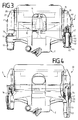
- the housing 2 encompasses a brake disc 4 in a U-shape with a leg 5, a housing bridge 6 and an inner leg 7.
- an actuator 8,9 having a cylinder 8 and a piston 9, which presses an inner brake pad 10 directly and an outer brake pad 11 indirectly via the housing bridge 6 and the outer leg 5 against the brake disc 4 when the brake is actuated.
- the brake pads 10, 11 have carrier plates 12, 13 and friction pads 14, 15.
- the housing 2 is slidably supported on two bolts 16. (Only one bolt 16 is visible in this figure.) The bolt 16 is screwed into the brake carrier 3.
- the housing 2 has a housing arm 17 with a bore 18.
- a damping sleeve 19 is arranged coaxially on the bolt 16, projecting in the bore 18 and on both sides of the bore 18.
- the partial-pad disc brake 1 is arranged in a wheel with a wheel contour 20.
- the brake disc 4 with a friction surface 21 rotates in the direction 22 during forward travel.
- the housing 2 and the brake carrier 3 are braced against one another by a spring 23.
- the carrier plate 12 of the brake lining 10 has two ends 24, 31, also called hook-shaped regions, which are spaced apart in the circumferential direction, each with a radially inward projection 25, 25 ', which is arranged in a groove 26, 26' of the brake carrier arranged near the brake disk 4 3 protrudes.
- the brake pad 10 is supported with its projecting surface 29 on a groove surface 30 of the brake carrier 3.
- the brake pad 10 When the brake is actuated in reverse, the brake pad 10 is supported with an end face 27 of the carrier plate 12 on a groove face 28 in the groove 26.
- the end 31 of the carrier plate 12 has surfaces 32, 33 which lie against the surfaces 34, 35 of the brake carrier 3 when the brake is actuated.
- the carrier plate 13 of the brake pad 11 has two bolts 36, also called warts, projections or knobs (only one bolt 36 is visible because of the sectional view), which serve to hold the housing 2 when the brake is actuated via the carrier plate 13 on the brake carrier 3 to support.
- the housing 2 has surfaces 37, 38 which rest on the bolt 36 in a rectangular shape.
- the bolts 36 are arranged vertically centrally and symmetrically on the side of the carrier plate 13 opposite the lining side.
- Edges 48, 49 of the hook-shaped regions 24, 31, which lie opposite the projections 25, are approximately flush with a carrier plate edge 12a.
- the edges 12a, 48, 49, which form an outer upper contour of the carrier plate 12 of the brake pad 10, lie outside the pivoting range of the housing bridge 6 of the housing 2.
- the upper contour 12a, 48, 49 of the brake pads 10, 11 is configured in this way that the housing 2 is pivotable about one of the bolts 16.
- the outer upper contour 12a, 48, 49 of the carrier plate 12 is predetermined. It is therefore advisable to support the housing 2 centrally on the outer carrier plate 13.
- FIG. 3 shows the partial lining disc brake 1 with the brake carrier 3, which has two support arms 39, 40 extending in the axial direction over the brake disc 4.
- the support arms 39, 40 with the mutually facing surfaces 28, 35 form a radially outwardly open shaft for receiving and guiding the brake linings 10, 11 and have the radially outwardly open grooves 26 which extend near the brake disk 4 in the brake application direction.
- the brake pads 10, 11 are slidably guided on the support arms 39, 40 and in the circumferential direction Brake disc 4 positively connected to the support arms 39.40 that at least at higher brake application forces, the circumferential forces occurring on the brake shoes are transmitted to both support arms 39.40.
- a bolt 41 which is identical to the bolt 16, is screwed into the support arm 40.
- the housing 2 has the housing arm 17 and a further housing arm 42 with a bore 43.
- the holes 18 and 43 also called eyes, are the same size.
- Arranged in the bore 43 between the bolt 41 and the housing arm 42 are two metal sleeves 44, also called bolt guides, which slide with the housing 2 on the bolt 41 when the brake is actuated.
- an elastic sealing cap 46 is arranged, which protects the guide against dirt and moisture and sealingly surrounds the bolt 41.
- a rubber-like sealing sleeve 47 is arranged between the housing arm 42 of the housing 2 and the support arm 40 of the brake carrier 3, and protects the bolt 41 between the brake carrier 3 and the housing 2. To open the housing 2, the bolt 16 is unscrewed from the brake carrier 3.
- the housing 2 can be pivoted about the bolt 41 after loosening the spring 23.
- the bolts 16 and 41 are in the housing arms 17 and 42 protruding laterally on the housing 2 and the support arms 39, 40, that is in positions so far laterally outwards or arranged that the housing 2 and the brake carrier 3 do not pivot when pivoting are a hindrance.
- the housing 2 has on its arm 52 a long guide made of a metallic protective cap 53 in which the pin 51 is arranged.
- a rubber-like protective sleeve 54 is arranged between the arm 52 and the brake carrier 3.
- the arm 52 of the housing 2 has two bores 55 and 56, the central axes of which are identical.
- the bore 56 is arranged in the region of the arm 52 and is shorter than the bore 55.
- the diameter of the bore 56 is larger than that of the bore 55.
- the bore 56 serves to receive a plastic or metal sleeve 57 which encases the bolt 51 and one Bead 58 of the protective sleeve 54, also called bellows, holds in contact with the arm 52. Otherwise, the partial lining disk brake 50 is constructed like the partial lining disk brake 1.
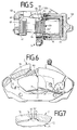
- the wire spring 59 is in the form of an annular or spiral and is resiliently inserted in a groove 60 of a piston 61 with an annular part 59 ′ shaped into a circle.
- One leg 62 of the piston spring 59 protrudes from the piston 61 and, with its end 63, clamps a directly actuated brake pad 64 against the brake carrier 3 or presses the piston-side brake pad 64 against the brake carrier 3 with its end 63.
- the brake pad 64 has a carrier plate 65 with two trapezoidal projections 66.
- the projections 66 of the external brake lining 67 serve to support the housing 68 on the brake carrier 3 when the brake is actuated via the carrier plate 69 of the brake lining 67.
- the housing bridge has two trapezoidal grooves, also called recesses, in which the projections 66 engage.
- the protrusions 66 replace the bolts 36.
- the projections 66 are arranged centrally in the region of a housing bridge 70 of the housing 2.
- the second projection 66 is arranged symmetrically and in mirror image to the axis of symmetry 71 and is not visible in this figure.
- the carrier plate 72 has a circular sector-shaped projection 74 which fits into a corresponding circular sector-shaped groove 75, also called a recess, of the housing 2 intervenes positively.
- This projection 74 is also arranged centrally in the region of the housing bridge 70.
- the radius of the projection 74 is slightly smaller than the radius of the groove 75, so that the housing 2 is supported on the brake carrier 3 at the level of the axis of symmetry 71 via the carrier plate 72.
- the housing 2 thus advantageously has a central guide for support on the brake pad 73.
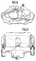
- the spring 81 is inserted with a spiral section 92 in a recess 82 on the carrier plate 72 and engages with its upper spring ends 83 in a recess 84 of the housing bridge 70 and thereby braces the brake pad 64.
- FIG. 9 shows a plan view of a partial lining disc brake with the spring 81.
- the spiral section 92 has two circular segments and a connecting web 93 between the circular segments.
- FIG. 10 shows a side view of the partial lining disc brake with the spring 81.
- the two circular segments 94, 95 are connected to one another by the connecting web 93, and the spring ends 83 adjoin the circular segments at the opposite ends.
- Fig. 11 shows a partial lining disc brake with two identical bolts 16, which are screwed into the support arms 39, 40. Both bolts 16 are mounted in the same damping sleeves 19 in the bores 18, 43 of the housing arms 17, 42. The damping sleeves 19 are closed with a cap 96.
- FIGS. 12 and 13 show the design of a carrier plate 72 for receiving a spring 81 which is supported on the housing bridge 6, 70 in a recess 84.
- the lower sections 85, 86 are components of the circular segments 94, 95 of the spring 81. They are supported on surfaces 87, 88 of the carrier plate 72 and are arranged to the side of a U-shaped projection 89.
- the carrier plate 72 advantageously has a widening with conical surfaces 90, 91 on the projection 89.
- the contact surfaces 97 for additional lateral support of the spring 81 are parallel to the braking surface of the brake pad.
- FIG 14, 15 and 16 show a partial lining disc brake 100 with a brake carrier 101 and a housing 102. Since the disc brake 100 is constructed symmetrically to a plane determined by the two axes of symmetry 103 and 104, only one of two bolt guides 105 and 106 described. A bolt 107 of the bolt guide 105 is screwed into an eye 108 of the brake carrier 101. The eye 108 is arranged in the axial direction behind a piston 109, so that the eye is not a hindrance to the directly actuated brake pad 110.
- the eye 108 lies in a horizontal plane 111, which lies between a horizontal plane 112, which is predetermined by the cylinder axis of the actuating unit, and a horizontal plane 113, which is predetermined by radial support points 114 and 115 of the carrier plate on the brake carrier 101.
- the carrier plate 118 has a circular sector-shaped projection 120 which is arranged symmetrically with respect to an axis of symmetry 121.
- the brake pad 116 is supported at its highest point 122, through which the axis of symmetry 121 runs.
- the projection 120 is formed in the shape of a sector of a circle and engages in a recess in the housing of the housing bridge 70 in the form of a sector of a circle.
- a length 123 of the projection 120 in the circumferential direction 124 is approximately one third of the total length 125 of the brake pad 116 in the circumferential direction 124.
- a radius 126 of the projection 120 has a length of 30 to 36 mm.
- the center point 127 to the radius 126 of the projection 120 when the brake pad 116 is inserted into the disc brake lies in the cylinder axis of the actuation unit.
- a radial height 126 'of the projection 120 is 13 mm.
- the inner support surfaces of the radial projection for the circumferential forces are at a distance 128 of approximately 120 to 150 mm.
- a chamfer 129 on an upper side 129 'to the rear side 129'' makes it easier to apply the brake pad 116 to the outer leg of the partial pad disc brake.
- FIG. 19 shows a brake lining 130 with a friction lining 131 and a carrier plate 132.
- the projection 120 is divided into two trapezoidal lugs 133 and 134, in the middle of which there is a groove-shaped recess 135.
- Surfaces 138, 139 are also rounded off with radius 126. The radius 126 is tolerated minus, the bridge radius 126 '' plus tolerated.
- FIG. 21 shows a machining on an underside 145 of the housing bridge 6.
- a recess surface 139' is machined.
- a further machined recess surface 140 follows radially outward.
- a slip chamfer 141 is provided between the two recess surfaces 139 'and 140.
- the machined recess surface 140 is followed by a raw part surface 142 which merges into the machined surface 140 via a slip chamfer 143.
- the tolerances of the cast Raw surface 142 to the machined surfaces 139 'and 140 are selected so that a maximum of a slip chamfer 143 can occur, which is chosen so small that the brake pad 116 can be applied to the outer leg 7 via the slip chamfers 143 and 141 during the first brake actuation. Ideally, the slip phase 143 approaches zero or does not exist.
- FIG. 22 shows a partial lining disc brake 1 with an outer leg 7 and a housing bridge 6, which has a pocket 144 at the buckling edge 138 '.
- This pocket 144 can receive corrosion products, so that a secure contact between the surfaces 74 'and 75' is always guaranteed.
- FIGS. 23 to 29 allow one-piece parts arranged at an angle to one another to be improved on their inner edges in such a way that an almost uniform stress curve is achieved in the transition region and that tensions, in particular tensile stresses, are degradable and early Cracking or an early breakup in gray cast iron or similar is avoided on these inner edges. Weight is also to be saved and the service life is to be increased. There should be no additional costs and smaller installation spaces should be possible.
- an arcuate contour on the inside at a joint between two parts (legs) that are integrally formed with one another and that are integrally formed with one another has continuously or sectionally different radii and, beginning with a large radius, decreasing in the direction of a load application point and smaller radii. Since the curve effect decreases at the same time as the bending moment increases, there is a uniform stress curve.
- the arcuate contour is used in the case of a notch that projects into a leg that extends essentially in the circumferential direction.
- the notches create the local ones Stress increases, so-called. Notch stresses.
- Notch stresses With an optimized notch shape, a tension reduction is achieved, so that the two legs that meet in a transition point do not break apart prematurely or be torn apart under load.
- the breaking load is also increased for brittle materials.
- the maximum stress is approximately in the center of the notch. Therefore, a large radius is selected in the previously highly stressed area and a small, ie sharp, radius is selected in the previously less stressed area.
- the arcuate contour delimits a radially inwardly projecting section between the two legs.
- a simple arrangement between two mutually perpendicular surfaces of the two L-shaped legs is achieved.
- the legs of the carrier plate are supported only outside the arcuate contour. This ensures that the arcuate contour is not damaged by the web of the brake carrier.
- the leg has two notches which delimit a projection which is supported on the web of the brake carrier.
- a brake carrier in which the web supports the brake lining with surfaces arranged essentially perpendicular to one another.
- the web has rounded or beveled edges at its radially outer end, so that the end, hereinafter referred to as the tip, does not engage in the arcuate contour of the carrier plate so as not to damage this arcuate contour and touches the carrier plate with minimal contact area and thus against it Prevents corrosion.
- the largest possible radius is achieved on the part of the carrier plate.
- the embodiment of a brake carrier which is integrated in the steering knuckle is aimed at.
- Integrated steering knuckle means that the brake carrier and steering knuckle are made in one piece.
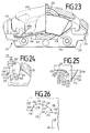
- FIG. 23 shows a partial lining disc brake 201 with a brake carrier 202, on which a housing 203 is mounted in an axially sliding manner.
- the housing 203 has an actuating unit 204, 205 comprising piston 204 and cylinder 205, which axially displaces a first brake pad 206 and thereby presses against a brake disk 207.
- a second brake lining 209 is pressed against the brake disk 207 by a reaction force through a leg 208 of the housing 203.
- the two brake pads 206, 209 are axially displaceably guided on support arms 210, 211.
- the housing 203 is braced on its leg 208 with a spring 212 against the brake carrier 202 on its support arms 210, 211.
- the carrier plate 214 has a hammer-head-shaped region 215 which ends laterally in the circumferential direction.
- the hammer head-shaped area 215 has an L-shaped section 216 with two L-shaped legs 217, 218 arranged with respect to one another.
- the L-shaped section 216 engages behind an axially extending, essentially radially outward web 219 of the brake carrier 202.
- a joint 220 also called a transition point or region, between the two legs 217, 218 there is a notch 221 with an arcuate contour 222 arranged.
- the leg 217 extends in the circumferential direction 217 '.
- FIG. 25 shows a schematic diagram with a section of a notch 221 and the arcuate contour 222 arranged therein.
- a load application point 224, to which a force 223 acts, and a notch base 225 define a load application lever 226.
- the arcuate contour 222 has sections 227, 228 and 229 different radii 230, 231 and 232, which increase in size from the smallest radius 230 starting over the radius 231 to the radius 232 with the distance from the load application point 224. Ideally, an infinite radius 232 'should result in section 229'.
- the bending moment 233 results from the load application lever 226.
- the invention is particularly suitable for a compact construction, ie a distance 226 'of the load application lever 226 is in Similar size to notch size. The larger the notch radius, the smaller the notch tension. The bending moment 233 grows linearly with the distance from the load application point 224.
- the notch 221 has the same height when the notch radius is greater when the notch radius increases with increasing distance from the load application point.
- a continuous transition is ideal.
- stepped radii 230 to 232 with tangential transitions.
- the tangential stress is a decisive parameter with regard to crack formation. Optimization is possible regardless of the type of stress (bending, tensile, compressive stress, etc.).
- One optimization criterion is to distribute the smallest possible constant tangential tension evenly over the entire notch base.
- Automatically optimizing computer programs can also be used to determine the optimal notch. In any case, it makes sense to approximate the curves obtained during the optimization using basic geometric elements (circle, straight line, etc.) in order to simplify production, construction and quality control. In principle, however, it is also possible to display contours of any curvature.
- the arcuate contour 222 of the notch 221 has a radius 230 in the curve section 227, a radius 231 in the curve section 228 and one in the curve section 229 Radius 232 on.
- the radius 230 is small, the radius 231 is larger and the radius 232 is largest.
- the arcuate contour 222 extends from the section 227 to a culmination point 235.
- the section 229 extends up to a point 236. From point 236, a curve section 237 with a smaller radius 238 and a straight line 239 complete the notch 221.
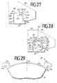
- FIG. 27 shows the web 219 of a brake carrier 240 on which the brake lining slides axially.
- the leg 217 has two notches 221, 241 which delimit a projection 242 which is supported on the web 219 of the brake carrier 240.
- the notch 221 has the radii 230, 231 and 232.
- the web 219 is rectangular with side faces 243, 244. These side surfaces 243, 244 engage with carrier plate surfaces 245, 246 when the brake is actuated, the carrier plate surface 246 forming a load application area. This arrangement is particularly advantageous in the case of an integrated construction of the brake carrier 240 if it is formed in one piece with a steering knuckle.
- the arcuate contour 222 with the three radii 230 to 232 is provided between the two L-shaped legs 217 and 218.
- the arcuate contour 222 merges directly (without forming a projection 242) into a leg surface 247.
- a further arc-shaped contour 255 with radii 248 to 250 adjoins the leg surface 247, the radius 248 being the largest and the radius 250 the smallest, so that the contours 222, 255 are mirror images of an axis of symmetry 255 'because a bearing reaction also occurs Expansion is negligible.
- the web 219 has such a tip 251 with bevelled surfaces 252, 253 that the surfaces 243, 244, 252, 253 and 254 do not fit into the intervene arcuate contours 222 and 255 so as not to injure them. Without a bevel, voltage peaks would occur in a contact zone.
- the arcuate contour 222 delimits a triangular, radially inwardly projecting section 256, a base area 257 of the section 256 being curved in accordance with the arcuate contour 222.
- the straight surface 254 of the web 219 is supported on the leg surface 247 of the leg 217. Surfaces 243 and 244 engage surfaces 245 and 246 when the brakes are applied.
- a push-pull principle is advantageously implemented, in which the brake pad is first pressed against the web 219 when driving forward, that is to say the surfaces 243 and 245 engage with one another, and the brake pad is pulled against the web 219 when the brake is applied more strongly, ie Surfaces corresponding to surfaces 244, 246 on the circumferentially opposite side of brake pad 206 engage with one another.
- a pull-push principle can be implemented just as advantageously for reasons of wear and comfort.
- FIGS. 27 and 28 show a carrier plate region 258 which ends laterally in the circumferential direction 217 ′ and has a U-shaped recess 259 which is delimited by the legs 217, 218 and a further leg 260 arranged parallel to the leg 218. This arrangement is advantageous for an integrated construction.
- the brake lining 261 has a carrier plate 262 with the carrier plate region 258 with the recess 259, which ends laterally in the circumferential direction 217 ′ and is arranged on an upper edge 265 of the carrier plate 262, and on one in the opposite direction in the circumferential direction 217 ′ on a carrier plate region 263 with a recess 264.
- the brake pad 261 is mirror-symmetrical to an axis of symmetry 266.
- Notch optimization can advantageously be used on all parts of the brake, namely on housings, brake carriers, brake linings, bolts, springs and clearing profiles.
Landscapes
- Engineering & Computer Science (AREA)
- General Engineering & Computer Science (AREA)
- Mechanical Engineering (AREA)
- Braking Arrangements (AREA)
Claims (42)
- Frein à disque à garnitures partielles, notamment pour véhicule automobile, comprenant un boîtier (2, 102), comportant un pont de boîtier (6, 70), un support de frein (3, 101), comportant deux bras de support (39, 40) parallèles et disposés à distance l'un de l'autre, et une garniture de frein (11, 73, 116, 130, 209) qui est guidée sur les bras de support (39, 40) de façon à pouvoir se déplacer en translation suivant la direction d'application du frein et comporte une plaquette de support (13, 72, 118, 132) et qui est reliée par complémentarité de formes aux bras de support (39, 40) suivant la direction des forces circonférentielles, les bras de support (39, 40) constituant, avec des surfaces (28, 30, 34, 35) se faisant face, une cage (26) ouverte vers l'extérieur et servant à recevoir et guider la garniture de frein (11, 73, 116, 130, 209), tandis que le boîtier (2, 102) est disposé de façon à pouvoir se déplacer axialement en translation sur des tiges (16, 41, 51, 107) à l'aide de moyens de guidage de tige et, par une surface (75', 139') située sur la face inférieure du pont de boîtier (6, 70), prend appui radialement contre le support de frein (3, 101) par l'intermédiaire de la plaquette de support (72, 118, 132) de la garniture extérieure de frein (73, 116, 130), caractérisé en ce qu'une saillie (74, 120, 133, 134) de la plaquette de support (13, 72, 118, 132) qui est située sur l'axe de symétrie (103, 104, 121) du frein (1, 100) prend appui en son milieu sur le boîtier (2, 102).
- Frein à disque à garnitures partielles suivant la revendication 1, caractérisé en ce que la saillie (74, 120) est réalisée en forme de secteur circulaire - de préférence en forme de demi-cercle - et s'emboîte dans une rainure en forme de secteur circulaire (75) du pont (6, 70) du boîtier dont le rayon (126') est supérieur au rayon (126) de la saillie (74, 120).
- Frein à disque à garnitures partielles suivant la revendication 1 ou 2, caractérisé en ce qu'au moins un évidement (135) en forme de rainure divise la saillie (133, 134) en au moins deux talons trapézoïdaux (133, 134).
- Frein à disque à garnitures partielles suivant l'une des revendications précédentes, caractérisé en ce que la plaquette de support (118) comporte, sur sa face supérieure s'étendant suivant la direction circonférentielle, un chanfrein (129) tourné vers sa face arrière (129'') qui est située à l'opposé de la garniture de friction (117).
- Frein à disque à garnitures partielles suivant l'une des revendications précédentes, caractérisé en ce qu'à l'endroit de l'arête (138') du coude formé entre le pont (6) du boîtier et la branche (7), ce boîtier (2, 102) comporte un réceptacle (144) situé dans la zone de la saillie (74').
- Frein à disque à garnitures partielles suivant l'une des revendications précédentes, caractérisé en ce que le pont (6) du boîtier comprend deux surfaces de logement (139', 140) décalées axialement et radialement et séparées par un chanfrein (141).
- Frein à disque à garnitures partielles suivant la revendication 6, caractérisé en ce que les surfaces du logement (139', 140) du pont (6) du boîtier sont usinées.
- Frein à disque à garnitures partielles suivant l'une des revendications précédentes, caractérisé en ce que le contour (12a, 48, 49) de la garniture de frein (10, 11) est situé à l'extérieur d'une zone de basculement du boîtier (2) et en ce que le boîtier (2) est agencé de façon à pouvoir basculer autour de l'une des tiges (16, 41, 51).
- Frein à disque à garnitures partielles suivant la revendication 8, caractérisé en ce que le boîtier (2) comporte des bras de boîtier (17, 42, 52) qui font saillie latéralement et présentent des alésages (18, 43, 56) et dans lesquels les tiges (16, 41, 51) sont disposées.
- Frein à disque à garnitures partielles suivant l'une des revendications précédentes, caractérisé en ce que le support de frein (101) comporte des oeils (108) qui font saillie suivant la direction axiale et dans lesquelles les tiges (107) sont disposées.
- Frein à disque à garnitures partielles suivant l'une des revendications précédentes, caractérisé en ce que la tige (51) est emboîtée à force d'une manière fixe dans le support de frein (3).
- Frein à disque à garnitures partielles suivant l'une des revendications 1 à 11, caractérisé en ce que le boîtier (2) comporte un capuchon métallique de protection (53) dans lequel la tige (51) est disposée.
- Frein à disque à garnitures partielles suivant la revendication 9, caractérisé en ce que, dans l'alésage (43), une douille métallique (44) est disposée entre la tige (41) et le bras (42) du boîtier.
- Frein à disque à garnitures partielles suivant l'une des revendications précédentes, caractérisé en ce que les tiges (16, 41) sont identiques.
- Frein à disque à garnitures partielles suivant l'une des revendications précédentes, caractérisé en ce que la tige (16, 41) est vissée dans le support de frein (3).
- Frein à disque à garnitures partielles suivant l'une des revendications précédentes, caractérisé en ce qu'un capuchon d'étanchéité (46) qui est disposé à une extrémité extérieure (45) de la tige (41).
- Frein à disque à garnitures partielles suivant l'une des revendications précédentes, caractérisé en ce qu'un soufflet d'éfanchéité (47) est disposé entre le bras (42) du boîtier et le bras de support (40).
- Frein à disque à garnitures partielles suivant l'une des revendications précédentes, caractérisé en ce que la plaquette extérieure de support (13) comporte des bossages (36) sur sa face située à l'opposé du côté de la garniture de friction (15).
- Frein à disque à garnitures partielles suivant l'une des revendications précédentes, caractérisé en ce que la garniture de frein (64) actionnée directement est immobilisée par un ressort de piston (59) de forme spirale et en ce qu'une partie annulaire (59') du ressort de piston (59) est emboîtée dans une gorge (60) d'un piston (61).
- Frein à disque à garnitures partielles suivant l'une des revendications précédentes, caractérisé en ce qu'un ressort (81) est emboîté dans un logement (82) de la plaquette de support (72) et exerce une action, par des extrémités supérieures (83) dans un évidement (84) du pont (6, 70) du boîtier.
- Frein à disque à garnitures partielles suivant la revendication 20, caractérisé en ce que la plaquette de support (72) comporte des surfaces d'appui (97) servant à l'appui transversal du ressort (81).
- Frein à disque à garnitures partielles suivant la revendication 11 ou 12 en combinaison avec la revendication 15, caractérisé en ce que le boîtier (2) est agencé de façon à pouvoir basculer autour de la tige (51) emboîtée à force, en ce que la tige (51) emboîtée à force est plus longue que la tige (16, 41) vissée et en ce que le capuchon métallique de protection (53) constitue des moyens de guidage longitudinal de la tige (51) emboîtée à force.
- Frein à disque à garnitures partielles suivant l'une des revendications précédentes, caractérisé en ce que la plaquette de support (12, 13, 72) comporte, aux extrémités (24, 31) situées à une certaine distance l'une de l'autre suivant la direction circonférentielle, des zones en forme de crochet (24, 31) comportant des saillies (25, 25') qui sont inclinées radialement vers l'intérieur et qui s'emboîtent dans les rainures (26) des bras de support (39, 40, 210, 211) du support de frein (3, 101, 202).
- Frein à disque à garnitures partielles suivant la revendication 23, caractérisé en ce que les bords supérieurs (48, 49) des zones (24, 31) en forme de crochet qui font face aux saillies (25) sont situés pratiquement dans l'alignement d'un bord (12a) de la plaquette de support.
- Garniture de frein pour frein à disque à garnitures partielles suivant l'une des revendications 2 à 11, comprenant une garniture de friction et une plaquette de support (72), caractérisée en ce que la plaquette de support (72) comporte, sur sa face supérieure s'étendant suivant la direction circonférentielle, une salle en forme de secteur de cercle (74) disposée suivant l'axe de symétrie (71) de la garniture de frein (73, 116, 130).
- Garniture de frein suivant la revendication 25, caractérisée en ce que, à ses extrémités (24, 31) situées à une certaine distance l'une de l'autre suivant la direction circonférentielle, la plaquette de support (12, 13, 72) comporte des zones (24, 31) en forme de crochet qui présentent des saillies (25) qui s'emboîtent dans les rainures (26) des bras de support (39, 40, 210, 211) du support de frein (3, 101, 202).
- Garniture de frein suivant la revendication 26, caractérisée en ce que les bords supérieurs (48, 49) des zones (24, 31) en forme de crochet qui font face aux saillies (25) sont situés pratiquement dans l'alignement d'un bord (12a) de la plaquette de support.
- Garniture de frein suivant la revendication 25, caractérisée en ce qu'il est ménagé dans la saillie (133, 134) au moins un évidement (135) qui divise cette saillie (133, 134) en deux talons (133, 134) au moins trapézoïdaux.
- Garniture de frein suivant l'une des revendications 25 à 28, caractérisée en ce que, sur sa face supérieure (129') qui s'étend suivant la direction circonférentielle (124), la plaquette de support comporte un chanfrein (129) dirigé vers la face arrière (129'').
- Garniture de frein suivant l'une des revendications 25 à 29, caractérisée en ce que la saillie (120) a une longueur (123) dans le sens circonférentiel (124) qui est comprise entre un cinquième et la moitié de la longueur totale (125) de la garniture de frein (116) suivant la direction circonférentielle (124), notamment est égale à un tiers de cette longueur totale (125).
- Garniture de frein suivant l'une des revendications 25 à 30, caractérisée en ce que la saillie (120) a un rayon (126) compris entre 25 et 40 mm, notamment entre 30 et 36 mm.
- Garniture de frein suivant l'une des revendications 25 à 31, caractérisée en ce que le centre (127) de l'arc de cercle de rayon (126) de la saillie (120) est situé sur l'axe du cylindre de l'unité d'actionnement lorsque la garniture de frein (116) est montée dans le frein à disque.
- Garniture de frein suivant l'une des revendications 25 à 32, caractérisée en ce que la hauteur radiale (126') de la saillie (120) au-dessus du bord supérieur (117') de la garniture de friction est égale au maximum à 20 mm, notamment à 13 mm.
- Garniture de frein suivant l'une des revendications 25 à 33, caractérisée en ce que le décalage radial (127') entre des points (122, 122', 122'') de la plaquette de support (118) qui servent à l'appui radial sur le support de frein (3, 101) et sur le boîtier (2, 102) a une valeur (127') comprise entre 30 et 50 mm, notamment entre 32 et 45 mm.
- Garniture de frein suivant l'une des revendications 25 à 34, caractérisée en ce que des surfaces d'appui intérieur (29, 34) des saillies (25, 25') orientées radialement vers l'intérieur, ces surfaces d'appui étant prévues pour les forces circonférentielles, comportent un espacement (128) compris entre 120 et 150 mm.
- Garniture de frein suivant l'une des revendications 25 à 35, comprenant une plaquette de support (214) qui se termine latéralement suivant la direction circonférentielle par une section (216) en L et qui, par cette section (216), s'accroche derrière un rebord (219) d'un support de frein (202, 240) qui s'étend axialement et est dirigé d'une manière pratiquement radiale vers l'extérieur, la section (216) en L étant constituée de deux branches (217, 218) qui, à l'endroit d'un emplacement de jonction (220), comportent un contour courbe (222, 255) disposé intérieurement, caractérisée en ce que le contour courbe (222, 255) comporte, notamment par tronçons, des rayons différents (230, 231, 232, 248, 249, 250), en commençant par un grand rayon (232, 248), puis, en diminuant en direction d'un point d'application de charge (224), des rayons plus petits (230, 231, 249, 250).
- Garniture de frein suivant la revendication 36, caractérisée en ce que le contour courbe (222, 255) fait partie d'une encoche (221, 241) qui pénètre dans la branche (217) s'étendant pratiquement suivant la direction circonférentielle (217').
- Garniture de frein suivant la revendication 37, caractérisée en ce que le contour courbe (222, 255) délimite entre les deux branches (217, 218, 260) une section (256) qui fait saillie radialement vers l'intérieur.
- Garniture de frein suivant la revendication 38, caractérisée en ce que les branches (217, 218, 260) de la plaquette de support prennent appui exclusivement à l'extérieur du contour courbe (222, 255).
- Garniture de frein suivant l'une des revendications 38 et 39, caractérisée en ce que la branche (217) comporte deux encoches (221, 241) qui délimitent une saillie (242) qui prend appui sur le rebord (219) du support de frein (202).
- Garniture de frein suivant l'une des revendications 38 et 39, caractérisée en ce que la branche (217) comporte deux contours courbes (222, 255) qui sont notamment symétriques par rapport à un axe de symétrie (255').
- Support de frein pour frein à disque à garnitures partielles, notamment pour véhicule automobile, comprenant deux bras de support (210, 211) qui sont disposés à distance l'un de l'autre suivant la direction d'une sécante au disque de frein et qui comprennent un rebord (219) qui s'étend axialement et est orienté d'une manière pratiquement radiale vers l'extérieur et qui s'accroche dans une section (216) en L, se terminant latéralement suivant la direction circonférentielle, d'une plaquette de support (214) d'une garniture de frein (206) suivant l'une des revendications précédentes, le rebord (219) prenant appui sur la garniture de frein (206) par au moins deux surfaces (244, 254) disposées d'une manière pratiquement perpendiculaire l'une à l'autre, caractérisé en ce qu'à son extrémité (251) située radialement à l'extérieur, le rebord (219) comporte des surfaces (252, 253) arrondies ou chanfreinées.
Applications Claiming Priority (6)
| Application Number | Priority Date | Filing Date | Title |
|---|---|---|---|
| DE3815733A DE3815733A1 (de) | 1988-05-07 | 1988-05-07 | Teilbelag-scheibenbremse |
| DE3815733 | 1988-05-07 | ||
| DE3827686 | 1988-08-16 | ||
| DE3827686A DE3827686A1 (de) | 1988-08-16 | 1988-08-16 | Bremsbacke |
| DE3910969A DE3910969C2 (de) | 1989-04-05 | 1989-04-05 | Teilbelag-Scheibenbremse |
| DE3910969 | 1989-04-05 |
Publications (2)
| Publication Number | Publication Date |
|---|---|
| EP0341610A1 EP0341610A1 (fr) | 1989-11-15 |
| EP0341610B1 true EP0341610B1 (fr) | 1994-01-19 |
Family
ID=27197594
Family Applications (1)
| Application Number | Title | Priority Date | Filing Date |
|---|---|---|---|
| EP89108168A Expired - Lifetime EP0341610B1 (fr) | 1988-05-07 | 1989-05-05 | Frein à disque à garniture partielle |
Country Status (6)
| Country | Link |
|---|---|
| EP (1) | EP0341610B1 (fr) |
| JP (1) | JP2779027B2 (fr) |
| KR (1) | KR970007217B1 (fr) |
| DE (1) | DE58906728D1 (fr) |
| ES (1) | ES2049275T3 (fr) |
| WO (1) | WO1989011046A1 (fr) |
Cited By (14)
| Publication number | Priority date | Publication date | Assignee | Title |
|---|---|---|---|---|
| WO1991005176A1 (fr) * | 1989-10-06 | 1991-04-18 | Alfred Teves Gmbh | Frein a disque a garniture partielle |
| EP0442048A1 (fr) * | 1990-02-01 | 1991-08-21 | ITT Automotive Europe GmbH | Plaquette de frein |
| WO1992004553A1 (fr) * | 1990-08-31 | 1992-03-19 | Alfred Teves Gmbh | Etrier flottant et plaquette de freins a disque a garniture partielle |
| WO1992017713A1 (fr) * | 1991-04-04 | 1992-10-15 | Alfred Teves Gmbh | Frein a disque a garniture partielle et a etrier fixe |
| WO1992018785A1 (fr) * | 1991-04-20 | 1992-10-29 | Alfred Teves Gmbh | Segment de frein a ressort de retenue |
| US5494140A (en) * | 1991-04-20 | 1996-02-27 | Alfred Teves Gmbh | Brake shoe with retaining spring |
| DE19614632A1 (de) * | 1996-04-13 | 1997-10-16 | Teves Gmbh Alfred | Teilbelag-Scheibenbremse |
| DE19739122A1 (de) * | 1997-09-06 | 1999-03-11 | Itt Mfg Enterprises Inc | Teilbelag-Scheibenbremse |
| EP1020656A2 (fr) | 1999-01-18 | 2000-07-19 | Continental Teves AG & Co. oHG | Méthode de fabrication d'un boítier et frein à disque à garnitures partielles avec un tel boítier |
| DE10007354A1 (de) * | 2000-02-18 | 2001-08-23 | Continental Teves Ag & Co Ohg | Scheibenbremse, insbesondere Schwimmsattel-Teilbelag-Scheibenbremse für Kraftfahrzeuge |
| EP1143163A2 (fr) | 2000-04-04 | 2001-10-10 | Continental Teves AG & Co. oHG | Etrier flottant / frein à disque pour un véhicule |
| DE10242102A1 (de) * | 2002-09-11 | 2004-03-25 | Continental Teves Ag & Co. Ohg | Führungsbolzen einer Schwimmsattel-Scheibenbremse |
| DE102004029462A1 (de) * | 2004-06-18 | 2006-01-05 | Continental Teves Ag & Co. Ohg | Schwimmsattel-Scheibenbremse mit Bolzenführungen |
| EP1499814B2 (fr) † | 2002-07-15 | 2013-12-11 | Freni Brembo S.p.A. | Plaquette de frein a disque |
Families Citing this family (17)
| Publication number | Priority date | Publication date | Assignee | Title |
|---|---|---|---|---|
| DE4318749A1 (de) * | 1993-06-05 | 1994-12-08 | Teves Gmbh Alfred | Bremsbelag für Scheibenbremsen |
| DE19534824A1 (de) * | 1995-09-20 | 1997-03-27 | Teves Gmbh Alfred | Schwimmsattel-Teilbelagscheibenbremse |
| JP3843379B2 (ja) * | 1997-02-19 | 2006-11-08 | 株式会社日立製作所 | ディスクブレーキ及びディスクブレーキ用パッド |
| JP2001304311A (ja) | 2000-04-27 | 2001-10-31 | Akebono Brake Ind Co Ltd | フローティングキャリパ型ディスクブレーキ |
| ES2289383T3 (es) * | 2003-04-28 | 2008-02-01 | Bpw Bergische Achsen Kommanditgesellschaft | Pinza portapastillas para un freno de disco, asi como forro de freno para un freno de disco. |
| US8714317B1 (en) * | 2006-03-31 | 2014-05-06 | Robert Bosch Gmbh | Disc brake |
| DE102008013514A1 (de) * | 2008-03-11 | 2009-09-17 | TRW KFZ-Ausrüstung GmbH | Scheibenbremse mit orientierungsgesichertem Einbau der Bremsbeläge |
| JP2010116954A (ja) * | 2008-11-12 | 2010-05-27 | Akebono Brake Ind Co Ltd | ディスクブレーキ |
| KR101681799B1 (ko) * | 2010-06-18 | 2016-12-12 | 인디언 헤드 인더스트리즈, 인코포레이티드 | 에어 디스크 브레이크용 전자 스트로크 센서 |
| JP5562294B2 (ja) * | 2011-06-30 | 2014-07-30 | 日信工業株式会社 | 車両用ディスクブレーキ |
| CA2781540A1 (fr) * | 2012-06-26 | 2013-12-26 | Ray Arbesman | Plaque de support pour frein a chanfrein a gradins |
| DE102014205232B4 (de) | 2013-11-21 | 2015-07-16 | Continental Teves Ag & Co. Ohg | Reibbelaganordnung für eine Scheibenbremse |
| DE102016201909A1 (de) | 2016-02-09 | 2017-08-10 | Continental Teves Ag & Co. Ohg | Kraftfahrzeugteilbelagscheibenbremse mit in einem rahmenförmigen Halter pull-abgestützten Reibbelägen |
| KR102657439B1 (ko) | 2016-10-11 | 2024-04-15 | 에이치엘만도 주식회사 | 차량 제어 장치 및 그 제어 방법 |
| KR101892929B1 (ko) | 2016-11-25 | 2018-10-04 | 주식회사 만도 | 캘리퍼 브레이크 |
| DE102017007021A1 (de) * | 2017-07-25 | 2019-01-31 | Lucas Automotive Gmbh | Bremsbelaganordnung für eine Fahrzeugbremse |
| JP7084174B2 (ja) | 2018-03-27 | 2022-06-14 | 曙ブレーキ工業株式会社 | フローティング型ディスクブレーキ |
Citations (1)
| Publication number | Priority date | Publication date | Assignee | Title |
|---|---|---|---|---|
| GB842913A (en) * | 1957-04-24 | 1960-07-27 | Automotive Prod Co Ltd | Improvements in or relating to disc brakes |
Family Cites Families (17)
| Publication number | Priority date | Publication date | Assignee | Title |
|---|---|---|---|---|
| DE2451604C2 (de) * | 1973-11-08 | 1983-04-21 | D.B.A. Bendix Lockheed Air Equipement S.A., 92115 Clichy, Hauts-de-Seine | Führung einer Bremsbacke von Scheibenbremsen |
| GB1519764A (en) * | 1974-08-28 | 1978-08-02 | Girling Ltd | Disc brakes |
| DE2804808C3 (de) * | 1978-02-04 | 1988-09-29 | Alfred Teves Gmbh, 6000 Frankfurt | Bremsbackenhalterung für eine Teilbelagscheibenbremse, insbesondere für Kraftfahrzeuge |
| US4311219A (en) * | 1978-11-16 | 1982-01-19 | Akebono Brake Industry Co., Ltd. | Caliper guiding mechanism for disc brake |
| JPS55132532U (fr) * | 1979-03-13 | 1980-09-19 | ||
| DE2926818A1 (de) * | 1979-07-03 | 1981-03-12 | Alfred Teves Gmbh, 6000 Frankfurt | Teilbelagscheibenbremse. |
| JPS56117968A (en) * | 1980-02-20 | 1981-09-16 | Mitsubishi Electric Corp | Detector for location of elevator |
| DE3014057A1 (de) * | 1980-04-11 | 1981-10-15 | Alfred Teves Gmbh, 6000 Frankfurt | Bremsbackenhalterung fuer eine teilbelagscheibenbremse, insbesondere fuer kraftfahrzeuge |
| DE3121890A1 (de) * | 1981-06-02 | 1982-12-16 | Alfred Teves Gmbh, 6000 Frankfurt | Bremsbackenhaltefeder |
| JPS58172133U (ja) * | 1982-05-14 | 1983-11-17 | 曙ブレーキ工業株式会社 | デイスクブレ−キ |
| DE3220632A1 (de) * | 1982-06-02 | 1983-12-08 | Alfred Teves Gmbh, 6000 Frankfurt | Bremsbackenanordnung |
| DE3243851A1 (de) * | 1982-11-26 | 1984-05-30 | Alfred Teves Gmbh, 6000 Frankfurt | Dichtungsanordnung fuer den fuehrungsbolzen einer schwimmsattel-teilbelagscheibenbremse |
| FR2539475B3 (fr) * | 1983-01-14 | 1985-10-25 | Journee Paul | Plaquette de friction pour frein a disque a guidages en queue d'aronde et procede pour sa fabrication |
| DE3415994A1 (de) * | 1983-10-21 | 1985-10-31 | Alfred Teves Gmbh, 6000 Frankfurt | Bremsbacke fuer scheibenbremsen |
| FR2563595B1 (fr) * | 1984-04-26 | 1986-07-18 | Dba | Ressort de patins de frein a disque a etrier coulissant, et frein a disque equipe d'un tel ressort |
| DE3514497C2 (de) * | 1985-04-22 | 1995-11-09 | Teves Gmbh Alfred | Schutzmanschette für eine Bolzenführung einer Teilbelag-Scheibenbremse |
| DE3621507C2 (de) * | 1986-06-27 | 1994-10-20 | Teves Gmbh Alfred | Bremsbacke für eine Teilbelag-Scheibenbremse |
-
1989
- 1989-05-05 WO PCT/EP1989/000496 patent/WO1989011046A1/fr unknown
- 1989-05-05 DE DE89108168T patent/DE58906728D1/de not_active Expired - Lifetime
- 1989-05-05 KR KR1019890702341A patent/KR970007217B1/ko not_active IP Right Cessation
- 1989-05-05 JP JP1505441A patent/JP2779027B2/ja not_active Expired - Lifetime
- 1989-05-05 ES ES89108168T patent/ES2049275T3/es not_active Expired - Lifetime
- 1989-05-05 EP EP89108168A patent/EP0341610B1/fr not_active Expired - Lifetime
Patent Citations (1)
| Publication number | Priority date | Publication date | Assignee | Title |
|---|---|---|---|---|
| GB842913A (en) * | 1957-04-24 | 1960-07-27 | Automotive Prod Co Ltd | Improvements in or relating to disc brakes |
Cited By (16)
| Publication number | Priority date | Publication date | Assignee | Title |
|---|---|---|---|---|
| WO1991005176A1 (fr) * | 1989-10-06 | 1991-04-18 | Alfred Teves Gmbh | Frein a disque a garniture partielle |
| EP0442048A1 (fr) * | 1990-02-01 | 1991-08-21 | ITT Automotive Europe GmbH | Plaquette de frein |
| WO1992004553A1 (fr) * | 1990-08-31 | 1992-03-19 | Alfred Teves Gmbh | Etrier flottant et plaquette de freins a disque a garniture partielle |
| US5297659A (en) * | 1990-08-31 | 1994-03-29 | Alfred Teves Gmbh | Floating caliper and brake shoe for spot-type disc brakes |
| WO1992017713A1 (fr) * | 1991-04-04 | 1992-10-15 | Alfred Teves Gmbh | Frein a disque a garniture partielle et a etrier fixe |
| WO1992018785A1 (fr) * | 1991-04-20 | 1992-10-29 | Alfred Teves Gmbh | Segment de frein a ressort de retenue |
| US5494140A (en) * | 1991-04-20 | 1996-02-27 | Alfred Teves Gmbh | Brake shoe with retaining spring |
| DE19614632A1 (de) * | 1996-04-13 | 1997-10-16 | Teves Gmbh Alfred | Teilbelag-Scheibenbremse |
| DE19739122A1 (de) * | 1997-09-06 | 1999-03-11 | Itt Mfg Enterprises Inc | Teilbelag-Scheibenbremse |
| EP1020656A2 (fr) | 1999-01-18 | 2000-07-19 | Continental Teves AG & Co. oHG | Méthode de fabrication d'un boítier et frein à disque à garnitures partielles avec un tel boítier |
| DE19901690A1 (de) * | 1999-01-18 | 2000-07-20 | Continental Teves Ag & Co Ohg | Verfahren zum Herstellen eines Gehäuses sowie Teilbelag-Scheibenbremse mit solch einem Gehäuse |
| DE10007354A1 (de) * | 2000-02-18 | 2001-08-23 | Continental Teves Ag & Co Ohg | Scheibenbremse, insbesondere Schwimmsattel-Teilbelag-Scheibenbremse für Kraftfahrzeuge |
| EP1143163A2 (fr) | 2000-04-04 | 2001-10-10 | Continental Teves AG & Co. oHG | Etrier flottant / frein à disque pour un véhicule |
| EP1499814B2 (fr) † | 2002-07-15 | 2013-12-11 | Freni Brembo S.p.A. | Plaquette de frein a disque |
| DE10242102A1 (de) * | 2002-09-11 | 2004-03-25 | Continental Teves Ag & Co. Ohg | Führungsbolzen einer Schwimmsattel-Scheibenbremse |
| DE102004029462A1 (de) * | 2004-06-18 | 2006-01-05 | Continental Teves Ag & Co. Ohg | Schwimmsattel-Scheibenbremse mit Bolzenführungen |
Also Published As
| Publication number | Publication date |
|---|---|
| JP2779027B2 (ja) | 1998-07-23 |
| JPH03501643A (ja) | 1991-04-11 |
| KR920700361A (ko) | 1992-02-19 |
| WO1989011046A1 (fr) | 1989-11-16 |
| DE58906728D1 (de) | 1994-03-03 |
| EP0341610A1 (fr) | 1989-11-15 |
| KR970007217B1 (ko) | 1997-05-07 |
| ES2049275T3 (es) | 1994-04-16 |
Similar Documents
| Publication | Publication Date | Title |
|---|---|---|
| EP0341610B1 (fr) | Frein à disque à garniture partielle | |
| EP0229618B1 (fr) | Frein à disque à étrier flottant à garniture partielle | |
| EP3555495B1 (fr) | Frein à disque pour un véhicule utilitaire et jeu de garnitures de frein | |
| DE2548927C2 (de) | Führung für den Sattel einer Schwimmsattel-Teilbelag-Scheibenbremse für Fahrzeuge | |
| EP0341392B1 (fr) | Frein à disque à garniture partielle | |
| DE3044185A1 (de) | Schwimmsattelscheibenbremse | |
| WO2016026617A1 (fr) | Frein à disque, étrier de frein et levier de frein rotatif | |
| DE3017307A1 (de) | Scheibenbremse | |
| DE3508039C2 (de) | Innen umgriffene Scheibenbremse, insbesondere für Kraftfahrzeuge | |
| DE3400544A1 (de) | Teilscheibenbremse | |
| DE1905576A1 (de) | Teilbelagscheibenbremse | |
| EP1476672B1 (fr) | Frein a disque equipe d'un dispositif d'ajustage a commande electrique | |
| EP0984188B1 (fr) | Frein à disque à garniture partielle | |
| WO1987003349A1 (fr) | Frein a disque a garniture partielle pour vehicules a moteur | |
| EP0929756B1 (fr) | Ressort de retenue pour boitier de frein a disque a garniture partielle | |
| EP0597893B2 (fr) | Frein a disque a etrier flottant a agencement confortable des segments | |
| DE3412062A1 (de) | Teilbelagscheibenbremse | |
| EP0847504A1 (fr) | Frein a disque a garniture partielle et a etrier flottant | |
| DE4106957A1 (de) | Federnde fuehrung fuer eine schwimmsattel-teilbelagscheibenbremse | |
| DE3910969C2 (de) | Teilbelag-Scheibenbremse | |
| DE3539602A1 (de) | Innenumgreifende scheibenbremse, insbesondere fuer kraftfahrzeuge | |
| EP0563689A2 (fr) | Frein à disque pour véhicule routier | |
| DE8816508U1 (de) | Teilbelag-Scheibenbremse | |
| EP0747609A2 (fr) | Frein à disque à garniture partielle | |
| EP0419599A1 (fr) | Frein a disque pour vehicules automobiles |
Legal Events
| Date | Code | Title | Description |
|---|---|---|---|
| PUAI | Public reference made under article 153(3) epc to a published international application that has entered the european phase |
Free format text: ORIGINAL CODE: 0009012 |
|
| 17P | Request for examination filed |
Effective date: 19890505 |
|
| AK | Designated contracting states |
Kind code of ref document: A1 Designated state(s): DE ES FR GB IT NL |
|
| 17Q | First examination report despatched |
Effective date: 19910620 |
|
| ITF | It: translation for a ep patent filed | ||
| RAP1 | Party data changed (applicant data changed or rights of an application transferred) |
Owner name: ITT AUTOMOTIVE EUROPE GMBH |
|
| GRAA | (expected) grant |
Free format text: ORIGINAL CODE: 0009210 |
|
| AK | Designated contracting states |
Kind code of ref document: B1 Designated state(s): DE ES FR GB IT NL |
|
| REF | Corresponds to: |
Ref document number: 58906728 Country of ref document: DE Date of ref document: 19940303 |
|
| GBT | Gb: translation of ep patent filed (gb section 77(6)(a)/1977) |
Effective date: 19940214 |
|
| ET | Fr: translation filed | ||
| REG | Reference to a national code |
Ref country code: ES Ref legal event code: FG2A Ref document number: 2049275 Country of ref document: ES Kind code of ref document: T3 |
|
| PLBE | No opposition filed within time limit |
Free format text: ORIGINAL CODE: 0009261 |
|
| STAA | Information on the status of an ep patent application or granted ep patent |
Free format text: STATUS: NO OPPOSITION FILED WITHIN TIME LIMIT |
|
| 26N | No opposition filed | ||
| REG | Reference to a national code |
Ref country code: GB Ref legal event code: IF02 |
|
| PGFP | Annual fee paid to national office [announced via postgrant information from national office to epo] |
Ref country code: ES Payment date: 20020513 Year of fee payment: 14 |
|
| PGFP | Annual fee paid to national office [announced via postgrant information from national office to epo] |
Ref country code: NL Payment date: 20020524 Year of fee payment: 14 |
|
| PG25 | Lapsed in a contracting state [announced via postgrant information from national office to epo] |
Ref country code: ES Free format text: LAPSE BECAUSE OF NON-PAYMENT OF DUE FEES Effective date: 20030506 |
|
| PG25 | Lapsed in a contracting state [announced via postgrant information from national office to epo] |
Ref country code: NL Free format text: LAPSE BECAUSE OF NON-PAYMENT OF DUE FEES Effective date: 20031201 |
|
| NLV4 | Nl: lapsed or anulled due to non-payment of the annual fee |
Effective date: 20031201 |
|
| REG | Reference to a national code |
Ref country code: ES Ref legal event code: FD2A Effective date: 20030506 |
|
| PGFP | Annual fee paid to national office [announced via postgrant information from national office to epo] |
Ref country code: DE Payment date: 20080531 Year of fee payment: 20 |
|
| PGFP | Annual fee paid to national office [announced via postgrant information from national office to epo] |
Ref country code: IT Payment date: 20080520 Year of fee payment: 20 |
|
| PGFP | Annual fee paid to national office [announced via postgrant information from national office to epo] |
Ref country code: FR Payment date: 20080521 Year of fee payment: 20 |
|
| PGFP | Annual fee paid to national office [announced via postgrant information from national office to epo] |
Ref country code: GB Payment date: 20080520 Year of fee payment: 20 |
|
| REG | Reference to a national code |
Ref country code: GB Ref legal event code: PE20 Expiry date: 20090504 |
|
| PG25 | Lapsed in a contracting state [announced via postgrant information from national office to epo] |
Ref country code: GB Free format text: LAPSE BECAUSE OF EXPIRATION OF PROTECTION Effective date: 20090504 |