EP0337488A2 - Radaufhängung - Google Patents
Radaufhängung Download PDFInfo
- Publication number
- EP0337488A2 EP0337488A2 EP89106739A EP89106739A EP0337488A2 EP 0337488 A2 EP0337488 A2 EP 0337488A2 EP 89106739 A EP89106739 A EP 89106739A EP 89106739 A EP89106739 A EP 89106739A EP 0337488 A2 EP0337488 A2 EP 0337488A2
- Authority
- EP
- European Patent Office
- Prior art keywords
- leaf spring
- vehicle body
- suspension system
- suspension
- motor vehicle
- Prior art date
- Legal status (The legal status is an assumption and is not a legal conclusion. Google has not performed a legal analysis and makes no representation as to the accuracy of the status listed.)
- Granted
Links
- 239000000725 suspension Substances 0.000 title claims abstract description 95
- 230000008859 change Effects 0.000 claims abstract description 23
- 230000008093 supporting effect Effects 0.000 claims abstract description 23
- 239000006096 absorbing agent Substances 0.000 claims description 12
- 230000035939 shock Effects 0.000 claims description 12
- 238000005452 bending Methods 0.000 claims description 11
- 238000006073 displacement reaction Methods 0.000 claims description 11
- 239000012530 fluid Substances 0.000 claims description 7
- 239000000543 intermediate Substances 0.000 description 11
- 230000008901 benefit Effects 0.000 description 3
- 230000001419 dependent effect Effects 0.000 description 3
- 238000000034 method Methods 0.000 description 3
- 230000008569 process Effects 0.000 description 3
- 230000001276 controlling effect Effects 0.000 description 2
- 239000000463 material Substances 0.000 description 2
- 230000008602 contraction Effects 0.000 description 1
- 238000010586 diagram Methods 0.000 description 1
- 238000004519 manufacturing process Methods 0.000 description 1
- 230000004044 response Effects 0.000 description 1
- 239000003381 stabilizer Substances 0.000 description 1
Images


Classifications
-
- B—PERFORMING OPERATIONS; TRANSPORTING
- B60—VEHICLES IN GENERAL
- B60G—VEHICLE SUSPENSION ARRANGEMENTS
- B60G17/00—Resilient suspensions having means for adjusting the spring or vibration-damper characteristics, for regulating the distance between a supporting surface and a sprung part of vehicle or for locking suspension during use to meet varying vehicular or surface conditions, e.g. due to speed or load
- B60G17/02—Spring characteristics, e.g. mechanical springs and mechanical adjusting means
- B60G17/027—Mechanical springs regulated by fluid means
- B60G17/0275—Mechanical springs regulated by fluid means the mechanical spring being a leaf spring
-
- B—PERFORMING OPERATIONS; TRANSPORTING
- B60—VEHICLES IN GENERAL
- B60G—VEHICLE SUSPENSION ARRANGEMENTS
- B60G11/00—Resilient suspensions characterised by arrangement, location or kind of springs
- B60G11/02—Resilient suspensions characterised by arrangement, location or kind of springs having leaf springs only
- B60G11/08—Resilient suspensions characterised by arrangement, location or kind of springs having leaf springs only arranged substantially transverse to the longitudinal axis of the vehicle
-
- B—PERFORMING OPERATIONS; TRANSPORTING
- B60—VEHICLES IN GENERAL
- B60G—VEHICLE SUSPENSION ARRANGEMENTS
- B60G17/00—Resilient suspensions having means for adjusting the spring or vibration-damper characteristics, for regulating the distance between a supporting surface and a sprung part of vehicle or for locking suspension during use to meet varying vehicular or surface conditions, e.g. due to speed or load
- B60G17/015—Resilient suspensions having means for adjusting the spring or vibration-damper characteristics, for regulating the distance between a supporting surface and a sprung part of vehicle or for locking suspension during use to meet varying vehicular or surface conditions, e.g. due to speed or load the regulating means comprising electric or electronic elements
- B60G17/019—Resilient suspensions having means for adjusting the spring or vibration-damper characteristics, for regulating the distance between a supporting surface and a sprung part of vehicle or for locking suspension during use to meet varying vehicular or surface conditions, e.g. due to speed or load the regulating means comprising electric or electronic elements characterised by the type of sensor or the arrangement thereof
-
- B—PERFORMING OPERATIONS; TRANSPORTING
- B60—VEHICLES IN GENERAL
- B60G—VEHICLE SUSPENSION ARRANGEMENTS
- B60G2202/00—Indexing codes relating to the type of spring, damper or actuator
- B60G2202/10—Type of spring
- B60G2202/11—Leaf spring
-
- B—PERFORMING OPERATIONS; TRANSPORTING
- B60—VEHICLES IN GENERAL
- B60G—VEHICLE SUSPENSION ARRANGEMENTS
- B60G2202/00—Indexing codes relating to the type of spring, damper or actuator
- B60G2202/10—Type of spring
- B60G2202/11—Leaf spring
- B60G2202/114—Leaf spring transversally arranged
-
- B—PERFORMING OPERATIONS; TRANSPORTING
- B60—VEHICLES IN GENERAL
- B60G—VEHICLE SUSPENSION ARRANGEMENTS
- B60G2202/00—Indexing codes relating to the type of spring, damper or actuator
- B60G2202/40—Type of actuator
- B60G2202/41—Fluid actuator
-
- B—PERFORMING OPERATIONS; TRANSPORTING
- B60—VEHICLES IN GENERAL
- B60G—VEHICLE SUSPENSION ARRANGEMENTS
- B60G2202/00—Indexing codes relating to the type of spring, damper or actuator
- B60G2202/40—Type of actuator
- B60G2202/41—Fluid actuator
- B60G2202/412—Pneumatic actuator
-
- B—PERFORMING OPERATIONS; TRANSPORTING
- B60—VEHICLES IN GENERAL
- B60G—VEHICLE SUSPENSION ARRANGEMENTS
- B60G2204/00—Indexing codes related to suspensions per se or to auxiliary parts
- B60G2204/80—Interactive suspensions; arrangement affecting more than one suspension unit
- B60G2204/82—Interactive suspensions; arrangement affecting more than one suspension unit left and right unit on same axle
-
- B—PERFORMING OPERATIONS; TRANSPORTING
- B60—VEHICLES IN GENERAL
- B60G—VEHICLE SUSPENSION ARRANGEMENTS
- B60G2400/00—Indexing codes relating to detected, measured or calculated conditions or factors
- B60G2400/25—Stroke; Height; Displacement
-
- B—PERFORMING OPERATIONS; TRANSPORTING
- B60—VEHICLES IN GENERAL
- B60G—VEHICLE SUSPENSION ARRANGEMENTS
- B60G2400/00—Indexing codes relating to detected, measured or calculated conditions or factors
- B60G2400/60—Load
-
- B—PERFORMING OPERATIONS; TRANSPORTING
- B60—VEHICLES IN GENERAL
- B60G—VEHICLE SUSPENSION ARRANGEMENTS
- B60G2401/00—Indexing codes relating to the type of sensors based on the principle of their operation
- B60G2401/12—Strain gauge
-
- B—PERFORMING OPERATIONS; TRANSPORTING
- B60—VEHICLES IN GENERAL
- B60G—VEHICLE SUSPENSION ARRANGEMENTS
- B60G2500/00—Indexing codes relating to the regulated action or device
- B60G2500/20—Spring action or springs
Definitions
- the present invention relates to a suspension system having means for easily determining a change in the condition of a suspension which is caused by an external force applied to the suspension.
- a vehicular suspension system including a shock absorber having a coil spring with a lower end coupled to a knuckle by which a road wheel is rotatably supported and an upper end coupled to a vehicle body through a resilient member with an electrically conductive rubber layer mounted thereon as a strain detector (see Japanese Laid-Open Utility Model Publication No. 60-106807).
- a motor vehicle equipped with such a suspension system is running, loads acting on the shock absorber and the resilient member are varied by irregularities on the road surface and swinging movement of the vehicle body, thus expanding and contracting the resilient member and the electrically conductive rubber member. Therefore, the road surface irregularities and the swinging movement of the vehicle body can be detected as changes in electric resistance which are brought about by the expansion and contraction of the rubber member.
- Japanese Laid-Open Utility Model Publication No. 60-155610 discloses another vehicular suspension system including a shock absorber having a coil spring with a lower end coupled to a knuckle by which a road wheel is rotatably supported and an upper end coupled to a vehicle body through a resilient member.
- the upper end of the shock absorber and a load detector are fastened together to the vehicle body.
- the load detector comprises a piezoelectric element for producing an output signal indicative of a change in a load on the shock absorber.
- Determination of a change in the condition of the suspension based on the detected value in the suspension assembly for controlling the attitude of the suspension lacks a desired degree of accuracy. Since the suspension system itself cannot detect a change in the height of the vehicle body from the ground as a change in the condition of the suspension which is induced by an external force applied, a separate vehicle height sensor is required. Because the load detector is mounted on the upper end of the shock absorber where a large load is concentrated, the suspension system is complex in structure, expensive to manufacture, and has a durability problem.
- a suspension system which is lightweight and of good space utility efficiency and has a suspension component interconnecting a road wheel and a vehicle body and including a resilient member or an elongate resiliency member extending transversely of the vehicle body, and also has at least one simple strain detector mounted on the resilient member for detecting a strain produced in the resilient member in response to an external force applied thereto, so that changes in the condition of a suspension which are caused by the applied external force, i.e., loads applied to the road wheel in three directions, or vertical, longitudinal, and transverse directions with respect to the vehicle body, and an amount of displacement of the road wheel with respect to the vehicle body, can easily be determined.
- a suspension system in a motor vehicle has a suspension including at least a resilient member extending transversely of the motor vehicle and having one end coupled to a knuckle, the resilient member supporting a vehicle body of the motor vehicle, and detector means disposed on the resilient member for detecting at least one of a change in a load and a change in the height of the motor vehicle from the ground due to an external force applied to the suspension.
- the resilient member comprises at least a leaf spring, and the detector means is attached to the leaf spring for detecting a strain of the leaf spring due to flexing thereof.
- the suspension system also includes arithmetic means for calculating at least one of a vertical load applied to a road wheel coupled to the knuckle and a displacement of the road wheel with respect to the vehicle body based on a change in the strain detected by the detector means.
- the resilient member may comprise an elongate resilient member extending between knuckles supporting two laterally spaced road wheels, respectively, of the motor vehicle, and having opposite ends coupled respectively to the knuckles, the suspension further including holder means coupled to the vehicle body and holding the elongate resilient member at two holding points which are swingable and slidable in the longitudinal direction of the elongate resilient member with respect to the vehicle body for bearing the load of the vehicle body.
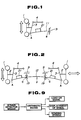
- FIG. 1 schematically shows a suspension system according to a first embodiment of the present invention, for use with one road wheel only.
- the suspension system shown in FIG. 1 is in the form of a double-wishbone suspension system comprising a road wheel 1, an axle 2, a knuckle 3, an upper arm 4, and a lower arm 11 comprising a leaf spring serving as an elongate resilient member and having resiliency in vertical directions and extending transversely of a motor vehicle.
- the leaf spring 11 has an outer end coupled at a supporting point A to a lower portion of the knuckle 3 and an inner end fixedly supporting a vehicle body 9 at a supporting point B.
- a damper comprising a shock absorber only is combined with the suspension system.
- the knuckle 3 that is coupled to the outer end of the leaf spring 11 at the supporting point A is normally urged downwardly under the resiliency of the leaf spring 11 with its inner end fixed to the vehicle body 9 at the supporting point B.
- the suspension system is reduced in weight and the damper in the form of a shock absorber only with no coil spring can be employed.
- a single strain detector 21 is mounted on an intermediate portion of the leaf spring 11.
- the strain detector 21 comprises a simple strain gage or the like for detecting a strain of the leaf spring 11 which is caused upon flexing thereof by an external force applied to the leaf spring 11.
- a detected signal from the strain detector 21 is applied to a vehicle-mounted computer (not shown) which calculates changes in the condition of the suspension caused by the external force applied thereto, through arithmetic operations or based on a data map.
- loads applied to the road wheel in three directions, i.e., vertical, longitudinal, and transverse directions of the motor vehicle, and changes in the loads are determined from changes in the strain of the leaf spring 11.
- a vertical displacement of the center of the road wheel (i.e., the axle 2) with respect to the vehicle body 9, for example, is determined to calculate the height of the vehicle body 9 from the ground.
- FIG. 2 shows a suspension system according to a second embodiment of the present invention in which an elongate leaf spring 12 extends transversely of a motor vehicle between suspensions supporting two laterally spaced road wheels. Knuckles 3 supporting road wheels 1, respectively, have lower portions coupled respectively to the opposite ends of the leaf spring 12 at supporting points A.
- the leaf spring 12 has an intermediate portion supported by two holder members 19 coupled to a vehicle body 9 at two laterally spaced holding points C of the leaf spring 12 for bearing the weight of the vehicle body 9, the holding points C being held by the holder member 19 so as to be swingable with the leaf spring 12 and slidable therewith in the longitudinal direction of the leaf spring 12 with respect to the vehicle body 9.
- the leaf spring 12 doubles as lower arms of the suspensions.
- a suitable load means (not shown) is interposed between the vehicle body 9 and a center, for example, of the intermediate portion of the leaf spring 12 between the holding points C. Dampers comprising shock absorbers only are associated respectively with the suspensions.
- An upward bending stress is applied as indicated by the arrow F by the load means from below or above the leaf spring 12 to the center of the leaf spring 12 or a certain range thereof between the holding points C.
- the leaf spring 12 is elastically deformed to lift the intermediate portion thereof, thus lowering the wheel supporting points A about the holding points C. Since the knuckles 3 are lowered with respect to the vehicle body 9, the height of the vehicle body from the ground is increased. Conversely, when a downward bending stress is applied to the intermediate portion of the leaf spring 12, the height of the vehicle body above the ground is reduced.
- the suspension system shown in FIG. 2 further includes two strain detectors 21, for example, mounted respectively on the leaf spring 12 at laterally spaced portions thereof, i.e., portions between the holding points C and the wheel supporting points A.
- Changes in the condition of the suspensions caused by external force applied thereto are determined from detected signals from the strain detectors 21.
- Loads imposed on the road wheels 1 in three directions, i.e., vertical, longitudinal, and transverse directions of the motor vehicle, and changes in the loads are determined from changes in the strains of the laterally spaced portions of the leaf spring 12.
- FIG. 3 illustrates a suspension system according to a third embodiment of the present invention.
- a lower arm 5 is provided separately from a leaf spring 13, and an intermediate portion of the lower arm 5 is coupled to the outer end of the leaf spring 13 at a supporting point A.
- the lower arm 5 has an outer end coupled to a knuckle 3 supporting a road wheel 1 and an inner end fixedly supporting a vehicle body 9 at a supporting point B.
- the suspension system of FIG. 3 offers substantially the same advantages as those of the first embodiment except that the leaf spring does not double as the lower arm.
- a single strain detector 21, for example, is mounted on an intermediate portion of the leaf spring 13 for detecting a strain of the leaf spring 13 to determine loads applied to the road wheel 1 in three directions, i.e., vertical, longitudinal, and transverse directions of the motor vehicle, and changes in the loads.
- an elongate leaf spring 14 extends transversely of a motor vehicle between suspensions supporting two laterally spaced road wheels.
- lower arms 5 are provided separately from the leaf spring 14.
- the leaf spring 14 has opposite ends coupled to intermediate portions, respectively, of the lower arms 5 at supporting points A.
- the leaf spring 14 also has an intermediate portion slidably and swingably held at two holding points C by holder members 19 coupled to a vehicle body 9.
- the suspension system of FIG. 4 also offers substantially the same advantages of those of the first embodiment except that the leaf spring does not double as the lower arm.
- the suspension system shown in FIG. 4 further includes two strain detectors 21, for example, mounted on the intermediate portion of the leaf spring 12 respectively at laterally spaced locations between the holding points C.
- Changes in the condition of the suspensions caused by external forces applied thereto are determined from detected signals from the strain detectors 21.
- Loads imposed on the road wheels 1 in three directions, i.e., vertical, longitudinal, and transverse directions of the motor vehicle, and changes in the loads are determined from changes in the strains of the laterally spaced locations of the intermediate portion of the leaf spring 14.
- strain detectors 21 may be selected as desired in view of objectives in designing the suspension system and other factors.
- the strain detec tor or detectors may be mounted on the entire surface or a partial surface of, or disposed within, each of the leaf springs 11, 12, 13, 14.
- H L k′1 ⁇ L + k′2 ⁇ R + K′ L ( ⁇ L , ⁇ R )
- H R k′3 ⁇ L + k′4 ⁇ R + K′ R ( ⁇ L , ⁇ R )
- H L k′1 ⁇ L + k′2 ⁇ R + k′3 ⁇ f L + k′4 ⁇ f R + K′ L ( ⁇ L , ⁇ R ,f L ,f R )
- H R k′5 ⁇ L + k′6 ⁇ R + k′7 ⁇ f L + k′8 ⁇ f R + K′ R ( ⁇ L , ⁇ R ,f R ,f L )
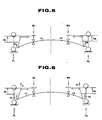
- the load means used herein comprises, for example, a bag 30 filled with a fluid 31 and disposed between the leaf spring 12 and a beam or a bag support member 40 supported by the holder members 19 and extending below the holder members 19.
- the bag 30 is prevented from being deformed downwardly by the beam or the bag support member 40.
- the amount of load applied to the leaf spring 12 can freely be adjusted by controlling the pressure of the fluid in the bag 30 with a pump or the like.
- the bag 30 is made of a flexible inexpansible material, and the filled fluid 31 comprises a gas as a compressible fluid.
- the bag 30 may be made of an expansible material, and the fluid 31 may be an inexpansible fluid.
- the present invention is based on the fact that an elongate resilient member (i.e., the leaf spring in the above embodiments) extending transversely of a motor vehicle as part of suspension components interconnecting road wheels and a motor vehicle body is subject to a strain dependent on an external force applied to the elongate resilient member.
- the amount of strain detected by at least one strain detector means mounted on the resilient member or leaf spring is processed by an arithmetic means to determine changes in the condition of a suspension which are caused by an external force imposed on the suspension, i.e., loads applied to the road wheels in the vertical, longitudinal, and transverse directions of the motor vehicle, displacements of the road wheels with respect to the vehicle body, and bending stresses applied to the leaf spring.
- At least two strain detectors are required, and if there are three unknown, at least three strain detectors are required. If no load is applied to the leaf spring by a load means (FIGS. 5 and 6), then the two strain detectors may be attached anywhere to the leaf spring. If a load is applied to the leaf spring by the load means (FIGS. 7 and 8), and the applied load is unknown, then at least two out of strain detectors mounted on the leaf spring must be located between the two holding points C in order to determine the unknown load. If the load applied by the load means is known, at least one strain detector should preferably be positioned between the holding points C.
- the leaf spring serving as the elongate resilient member may double as upper arms or may be connected to upper arms.
- the suspension or suspensions to which the present invention can be applied are not limited to double-wishbone suspensions, but may be strut suspensions.
- the height of a motor vehicle from the ground can be adjusted by using a leaf spring with its longitudinal axis extending longitudinally of the motor vehicle.
- the strain detectors used are simple in structure as they are only required to detect any strain of the resilient member, and are good in space utility efficiency, and lightweight, but nevertheless produce signals which are employed to determine loads on road wheels in vertical, longitudinal, and transverse directions of a motor vehicle, and displacements of the road wheels with respect to the motor vehicle body. By using detected signals from the strain detectors and results of arithmetic operations on the detected signals, suspension control can easily be performed.
Landscapes
- Engineering & Computer Science (AREA)
- Mechanical Engineering (AREA)
- Vehicle Body Suspensions (AREA)
- Force Measurement Appropriate To Specific Purposes (AREA)
Priority Applications (1)
| Application Number | Priority Date | Filing Date | Title |
|---|---|---|---|
| AT89106739T ATE90919T1 (de) | 1988-04-15 | 1989-04-14 | Radaufhaengung. |
Applications Claiming Priority (2)
| Application Number | Priority Date | Filing Date | Title |
|---|---|---|---|
| JP63094074A JPH01266005A (ja) | 1988-04-15 | 1988-04-15 | サスペンション装置 |
| JP94074/88 | 1988-04-15 |
Publications (3)
| Publication Number | Publication Date |
|---|---|
| EP0337488A2 true EP0337488A2 (de) | 1989-10-18 |
| EP0337488A3 EP0337488A3 (en) | 1990-10-24 |
| EP0337488B1 EP0337488B1 (de) | 1993-06-23 |
Family
ID=14100350
Family Applications (1)
| Application Number | Title | Priority Date | Filing Date |
|---|---|---|---|
| EP89106739A Expired - Lifetime EP0337488B1 (de) | 1988-04-15 | 1989-04-14 | Radaufhängung |
Country Status (6)
| Country | Link |
|---|---|
| US (1) | US4997202A (de) |
| EP (1) | EP0337488B1 (de) |
| JP (1) | JPH01266005A (de) |
| AT (1) | ATE90919T1 (de) |
| CA (1) | CA1311771C (de) |
| DE (1) | DE68907253T2 (de) |
Cited By (12)
| Publication number | Priority date | Publication date | Assignee | Title |
|---|---|---|---|---|
| EP0386748A1 (de) * | 1989-03-08 | 1990-09-12 | Honda Giken Kogyo Kabushiki Kaisha | Aufhängungssystem für Motorfahrzeuge |
| WO1994021480A1 (en) * | 1993-03-20 | 1994-09-29 | Lucas Industries Public Limited Company | Vehicle force transducer system |
| WO1998057814A1 (fr) * | 1997-06-16 | 1998-12-23 | Patrick Pascal Labbe | Structure de suspension notamment pour vehicule automobile |
| WO2003039894A1 (de) * | 2001-11-06 | 2003-05-15 | ZF Lemförder Metallwaren AG | Fahrwerksteil aus faserverstärkten kunststoffen mit integriertem sensor |
| WO2003055706A1 (fr) * | 2001-12-22 | 2003-07-10 | Patrick Pascal Labbe | Systeme de suspension d'un vehicule |
| EP1905618A1 (de) * | 2006-11-29 | 2008-04-02 | PM Group PLC | System zur Anzeige des Beladungszustandes von einem Fahrzeug |
| EP2072294A1 (de) * | 2007-12-18 | 2009-06-24 | Iveco S.p.A. | Verfahren und System zum Erfassen der Last eines mit nichtpneumatischen Aufhängungen ausgestatteten Fahrzeugs |
| US20120161411A1 (en) * | 2010-12-28 | 2012-06-28 | GM Global Technology Operations LLC | Vehicle with a leaf spring element for the spring suspension of the vehicle |
| EP2791640B1 (de) * | 2011-12-13 | 2018-10-17 | Renault S.A.S. | Feder mit eingebautem verformungssensor |
| CN111623909A (zh) * | 2019-02-28 | 2020-09-04 | 北京新能源汽车股份有限公司 | 一种双叉臂二力杆的受力测试方法 |
| EP4000971A1 (de) * | 2020-11-24 | 2022-05-25 | Volvo Truck Corporation | Verfahren und steuereinheit zur steuerung eines fahrgestellsystems in einem fahrzeug mit einer blattfeder |
| CN120063544A (zh) * | 2025-04-28 | 2025-05-30 | 陕西雷帕得悬架系统有限公司 | 一种汽车板簧应力检测方法 |
Families Citing this family (18)
| Publication number | Priority date | Publication date | Assignee | Title |
|---|---|---|---|---|
| EP0363570B1 (de) * | 1988-10-13 | 1996-02-21 | Japan Electronics Industry, Ltd. | Strassenoberflächen-Reibungsaufnehmer und Strassenoberflächen-Reibungskoeffizienten-Aufnehmer und Fahrzeug-Blockierschutz-Bremsanlage |
| JP2587627Y2 (ja) * | 1990-05-28 | 1998-12-24 | 株式会社ユニシアジェックス | 減衰力制御装置 |
| JP2612642B2 (ja) * | 1991-01-17 | 1997-05-21 | 本田技研工業株式会社 | 横置きリーフスプリング式懸架装置 |
| US5670345A (en) * | 1995-06-07 | 1997-09-23 | Arctech, Inc. | Biological production of humic acid and clean fuels from coal |
| US6273441B1 (en) * | 1999-04-27 | 2001-08-14 | Thomas Neavitt | Vehicle suspension stabilizing device |
| GB2364234A (en) * | 2000-07-04 | 2002-01-23 | D D S A Internat Ltd | Child's garment |
| US6659482B2 (en) * | 2002-01-03 | 2003-12-09 | Meritor Light Vehicle Technology, Llc | Composite spring and control arm |
| US20050023792A1 (en) * | 2003-08-01 | 2005-02-03 | Miller Steven R. | Lateral leaf spring with inboard air spring trailer suspension |
| JP2005121405A (ja) * | 2003-10-15 | 2005-05-12 | Yazaki Corp | 車両用自重計 |
| WO2010002460A1 (en) * | 2008-07-02 | 2010-01-07 | Ciris Energy, Inc. | Method for optimizing in-situ bioconversion of carbon-bearing formations |
| US8485543B2 (en) * | 2009-04-29 | 2013-07-16 | Reyco Granning, Llc | Independent suspension and steering assembly |
| CN102822346A (zh) * | 2009-12-18 | 2012-12-12 | 西里斯能源公司 | 煤至甲烷和其它有用产物的生物气化 |
| US9452657B1 (en) * | 2015-12-22 | 2016-09-27 | Ford Global Technologies, Llc | Height determination for two independently suspended wheels using a height sensor for only one wheel |
| DE102017103898A1 (de) * | 2017-02-24 | 2018-08-30 | Dr. Ing. H.C. F. Porsche Aktiengesellschaft | Fahrzeugachsanordnung |
| DE102017113971B4 (de) * | 2017-06-23 | 2024-09-05 | Dr. Ing. H.C. F. Porsche Aktiengesellschaft | Querblattfederanordnung einer Fahrwerksachse eines Kraftfahrzeuges |
| DE102018200459B4 (de) * | 2018-01-12 | 2022-02-24 | Ford Global Technologies, Llc | Verbindungsanordnung zur Verbindung einer Blattfeder und einer Lenkereinheit |
| US11084349B2 (en) * | 2019-01-31 | 2021-08-10 | Tenneco Automotive Operating Company Inc. | Leaf spring and actuator control systems and methods |
| DE102019207658A1 (de) * | 2019-05-24 | 2020-11-26 | Continental Automotive Gmbh | Sensorvorrichtung zum Erfassen des Abstandes zwischen einem Achskörper eines Fahrzeugrades und einer Fahrzeugkarosserie |
Family Cites Families (22)
| Publication number | Priority date | Publication date | Assignee | Title |
|---|---|---|---|---|
| FR664698A (fr) * | 1928-09-15 | 1929-09-06 | Suspension pneumatique à récupération applicable aux véhicules | |
| DE583749C (de) * | 1932-05-08 | 1933-09-08 | Jos Ganz Dipl Ing | Achsanordnung, insbesondere fuer Kraftfahrzeuge |
| US3204717A (en) * | 1961-11-30 | 1965-09-07 | Ford Motor Co | Vehicle power plant and wheel suspension system |
| US3140083A (en) * | 1962-01-23 | 1964-07-07 | Pasco Air Aid Inc | Auxiliary vehicle air spring |
| US3169026A (en) * | 1962-11-14 | 1965-02-09 | American Motors Corp | Vehicle wheel suspension system |
| FR1483928A (fr) * | 1966-04-27 | 1967-06-09 | Saviem | Perfectionnements aux suspensions oléopneumatiques |
| US3499662A (en) * | 1967-07-10 | 1970-03-10 | Mahrle F Paul | Air cushion system for vehicles |
| DE2541841A1 (de) * | 1975-09-19 | 1977-03-24 | Volkswagenwerk Ag | Kraftfahrzeug mit im niveau geregelter achse |
| DE2722015A1 (de) * | 1977-05-14 | 1978-11-16 | Trenkamp & Gehle | Federvorrichtung fuer radachsen strassengebundener nutzfahrzeuge |
| DE2927486A1 (de) * | 1979-07-07 | 1981-01-22 | Daimler Benz Ag | Achsaufhaengung, insbesondere hinterachsaufhaengung, fuer kraftfahrzeuge |
| DE3004158C2 (de) * | 1980-02-05 | 1984-08-30 | M.A.N. Maschinenfabrik Augsburg-Nürnberg AG, 8000 München | Vorrichtung zum Anheben einer nicht angetriebenen starren Fahrzeugachse |
| GB2080552B (en) * | 1980-07-12 | 1984-11-21 | Rubery Owen Group Services Ltd | Measuring loads |
| JPS58175236U (ja) * | 1982-05-18 | 1983-11-24 | カヤバ工業株式会社 | 減衰力調整式緩衝器ユニツト |
| JPS59213509A (ja) * | 1983-05-16 | 1984-12-03 | Chuo Spring Co Ltd | 車高調整装置 |
| JPS60106807A (ja) * | 1983-11-15 | 1985-06-12 | Mitsui Petrochem Ind Ltd | 超高分子量エチレン系ポリオレフイン粉末 |
| FR2556993B1 (fr) * | 1983-12-22 | 1986-09-19 | Somafer Sa | Outil pour le nettoyage des rigoles de coulee |
| US4619467A (en) * | 1984-04-16 | 1986-10-28 | Lafferty James W | Variable rate air spring apparatus for vehicle suspension |
| EP0218322A1 (de) * | 1985-08-12 | 1987-04-15 | Ford Motor Company Limited | Radaufhängung mit einer quer eingebauten Blattfeder |
| DE3530353A1 (de) * | 1985-08-24 | 1987-03-05 | Opel Adam Ag | Radaufhaengung fuer fahrzeuge |
| IT1197357B (it) * | 1986-10-07 | 1988-11-30 | Pirelli Accessori Ind | Dispositivo di sospensione per autoveicoli |
| DE3854002T2 (de) * | 1987-03-12 | 1995-09-28 | Honda Motor Co Ltd | Niveauregelung für Kraftfahrzeuge. |
| JPH01145214A (ja) * | 1987-12-01 | 1989-06-07 | Honda Motor Co Ltd | 横置きリーフスプリング式サスペンション |
-
1988
- 1988-04-15 JP JP63094074A patent/JPH01266005A/ja active Granted
-
1989
- 1989-04-14 AT AT89106739T patent/ATE90919T1/de not_active IP Right Cessation
- 1989-04-14 EP EP89106739A patent/EP0337488B1/de not_active Expired - Lifetime
- 1989-04-14 DE DE89106739T patent/DE68907253T2/de not_active Expired - Fee Related
- 1989-04-14 US US07/338,116 patent/US4997202A/en not_active Expired - Fee Related
- 1989-04-17 CA CA000596920A patent/CA1311771C/en not_active Expired - Lifetime
Cited By (22)
| Publication number | Priority date | Publication date | Assignee | Title |
|---|---|---|---|---|
| EP0386748A1 (de) * | 1989-03-08 | 1990-09-12 | Honda Giken Kogyo Kabushiki Kaisha | Aufhängungssystem für Motorfahrzeuge |
| US5058918A (en) * | 1989-03-08 | 1991-10-22 | Honda Giken Kogyo Kabushiki Kaisha | Suspension system for motor vehicle |
| WO1994021480A1 (en) * | 1993-03-20 | 1994-09-29 | Lucas Industries Public Limited Company | Vehicle force transducer system |
| WO1998057814A1 (fr) * | 1997-06-16 | 1998-12-23 | Patrick Pascal Labbe | Structure de suspension notamment pour vehicule automobile |
| US7083199B2 (en) | 2001-11-06 | 2006-08-01 | ZF Lemförder Metallwaren AG | Chassis part consisting of fiber-reinforced plastics, equipped with an integrated sensor |
| WO2003039894A1 (de) * | 2001-11-06 | 2003-05-15 | ZF Lemförder Metallwaren AG | Fahrwerksteil aus faserverstärkten kunststoffen mit integriertem sensor |
| WO2003055706A1 (fr) * | 2001-12-22 | 2003-07-10 | Patrick Pascal Labbe | Systeme de suspension d'un vehicule |
| US8412485B2 (en) | 2006-11-29 | 2013-04-02 | Vishay Pm Onboard Ltd. | System and method of monitoring a load condition of a vehicle |
| EP1905618A1 (de) * | 2006-11-29 | 2008-04-02 | PM Group PLC | System zur Anzeige des Beladungszustandes von einem Fahrzeug |
| WO2008043578A1 (en) * | 2006-11-29 | 2008-04-17 | Vishay Pm Onboard Ltd | System for indicating the state of loading of a vehicle |
| USRE46706E1 (en) | 2006-11-29 | 2018-02-13 | Vpg Systems U.K., Limited | System and method of monitoring a load condition of a vehicle |
| US7761258B2 (en) | 2006-11-29 | 2010-07-20 | Vishay Pm Onboard Ltd. | Method of monitoring a load condition of a vehicle |
| GB2444277B (en) * | 2006-11-29 | 2012-02-08 | Vishay Pm Onboard Ltd | System and method for indicating the state of loading of a vehicle |
| EP2075145A1 (de) * | 2007-12-18 | 2009-07-01 | Iveco S.p.A. | Verfahren und System zum Erfassen der Last eines mit nichtpneumatischen Aufhängungen ausgestatteten Fahrzeugs |
| EP2072294A1 (de) * | 2007-12-18 | 2009-06-24 | Iveco S.p.A. | Verfahren und System zum Erfassen der Last eines mit nichtpneumatischen Aufhängungen ausgestatteten Fahrzeugs |
| US20120161411A1 (en) * | 2010-12-28 | 2012-06-28 | GM Global Technology Operations LLC | Vehicle with a leaf spring element for the spring suspension of the vehicle |
| US8632078B2 (en) * | 2010-12-28 | 2014-01-21 | GM Global Technology Operations LLC | Vehicle with a leaf spring element for the spring suspension of the vehicle |
| EP2791640B1 (de) * | 2011-12-13 | 2018-10-17 | Renault S.A.S. | Feder mit eingebautem verformungssensor |
| CN111623909A (zh) * | 2019-02-28 | 2020-09-04 | 北京新能源汽车股份有限公司 | 一种双叉臂二力杆的受力测试方法 |
| CN111623909B (zh) * | 2019-02-28 | 2021-07-30 | 北京新能源汽车股份有限公司 | 一种双叉臂二力杆的受力测试方法 |
| EP4000971A1 (de) * | 2020-11-24 | 2022-05-25 | Volvo Truck Corporation | Verfahren und steuereinheit zur steuerung eines fahrgestellsystems in einem fahrzeug mit einer blattfeder |
| CN120063544A (zh) * | 2025-04-28 | 2025-05-30 | 陕西雷帕得悬架系统有限公司 | 一种汽车板簧应力检测方法 |
Also Published As
| Publication number | Publication date |
|---|---|
| CA1311771C (en) | 1992-12-22 |
| US4997202A (en) | 1991-03-05 |
| EP0337488B1 (de) | 1993-06-23 |
| JPH01266005A (ja) | 1989-10-24 |
| DE68907253D1 (de) | 1993-07-29 |
| EP0337488A3 (en) | 1990-10-24 |
| DE68907253T2 (de) | 1993-11-04 |
| JPH0577524B2 (de) | 1993-10-26 |
| ATE90919T1 (de) | 1993-07-15 |
Similar Documents
| Publication | Publication Date | Title |
|---|---|---|
| EP0337488A2 (de) | Radaufhängung | |
| EP0174007B1 (de) | Aufbau eines Kraftfahrzeugfederbeines mit verstellbaren Tragflächen | |
| US6688620B2 (en) | Vehicle suspension with camber control | |
| EP0279507A2 (de) | Regelungssystem für Kraftfahrzeugaufhängungsvorrichtung | |
| WO1997030858A2 (en) | Constant force suspension, near constant force suspension, and associated control algorithms | |
| EP0283879B1 (de) | Niveauregelung für Kraftfahrzeuge | |
| JPH0365414A (ja) | 能動型サスペンション | |
| EP1138531A1 (de) | Hydraulisches Antiwank-Aufhängungssystem für Kraftfahrzeuge | |
| EP0277788B1 (de) | Kraftfahrzeugaufhängung mit regelbarer Vorrichtung und Regelvorrichtung dafür | |
| JPH0585369B2 (de) | ||
| JPH07304318A (ja) | 能動懸架装置 | |
| EP0386748B1 (de) | Aufhängungssystem für Motorfahrzeuge | |
| JPH06286447A (ja) | 自動車のサスペンション装置 | |
| JPH058625A (ja) | 車両用ばね装置および懸架装置 | |
| EP0000979A1 (de) | Starrachsaufhängung für Fahrzeuge | |
| JP3156502B2 (ja) | サスペンション予見制御装置 | |
| JP2997984B2 (ja) | 車両用エアサスペンション装置 | |
| JPH0612136B2 (ja) | キャブの弾性支持装置 | |
| JPH0640231A (ja) | 車高検出器の取付け構造 | |
| JPH08207541A (ja) | 車両用減衰力付与機構のための電気制御装置 | |
| JPH0524421A (ja) | 車両用懸架装置 | |
| JPH0885315A (ja) | リアサスペンション装置 | |
| JPS61218412A (ja) | 車体姿勢制御装置 | |
| JPH04262910A (ja) | 車両用姿勢制御装置 | |
| KR0185445B1 (ko) | 자동차용 현가시스템 |
Legal Events
| Date | Code | Title | Description |
|---|---|---|---|
| PUAI | Public reference made under article 153(3) epc to a published international application that has entered the european phase |
Free format text: ORIGINAL CODE: 0009012 |
|
| AK | Designated contracting states |
Kind code of ref document: A2 Designated state(s): AT CH DE FR GB IT LI NL SE |
|
| PUAL | Search report despatched |
Free format text: ORIGINAL CODE: 0009013 |
|
| AK | Designated contracting states |
Kind code of ref document: A3 Designated state(s): AT CH DE FR GB IT LI NL SE |
|
| 17P | Request for examination filed |
Effective date: 19910412 |
|
| 17Q | First examination report despatched |
Effective date: 19920220 |
|
| GRAA | (expected) grant |
Free format text: ORIGINAL CODE: 0009210 |
|
| AK | Designated contracting states |
Kind code of ref document: B1 Designated state(s): AT CH DE FR GB IT LI NL SE |
|
| PG25 | Lapsed in a contracting state [announced via postgrant information from national office to epo] |
Ref country code: IT Free format text: LAPSE BECAUSE OF FAILURE TO SUBMIT A TRANSLATION OF THE DESCRIPTION OR TO PAY THE FEE WITHIN THE PRE;WARNING: LAPSES OF ITALIAN PATENTS WITH EFFECTIVE DATE BEFORE 2007 MAY HAVE OCCURRED AT ANY TIME BEFORE 2007. THE CORRECT EFFECTIVE DATE MAY BE DIFFERENT FROM THE ONE RECORDED.SCRIBED TIME-LIMIT Effective date: 19930623 Ref country code: NL Effective date: 19930623 Ref country code: LI Effective date: 19930623 Ref country code: SE Effective date: 19930623 Ref country code: AT Effective date: 19930623 Ref country code: CH Effective date: 19930623 |
|
| REF | Corresponds to: |
Ref document number: 90919 Country of ref document: AT Date of ref document: 19930715 Kind code of ref document: T |
|
| REF | Corresponds to: |
Ref document number: 68907253 Country of ref document: DE Date of ref document: 19930729 |
|
| ET | Fr: translation filed | ||
| REG | Reference to a national code |
Ref country code: CH Ref legal event code: PL |
|
| NLV1 | Nl: lapsed or annulled due to failure to fulfill the requirements of art. 29p and 29m of the patents act | ||
| PLBE | No opposition filed within time limit |
Free format text: ORIGINAL CODE: 0009261 |
|
| STAA | Information on the status of an ep patent application or granted ep patent |
Free format text: STATUS: NO OPPOSITION FILED WITHIN TIME LIMIT |
|
| 26N | No opposition filed | ||
| PGFP | Annual fee paid to national office [announced via postgrant information from national office to epo] |
Ref country code: FR Payment date: 19950425 Year of fee payment: 7 |
|
| PG25 | Lapsed in a contracting state [announced via postgrant information from national office to epo] |
Ref country code: FR Effective date: 19961227 |
|
| REG | Reference to a national code |
Ref country code: FR Ref legal event code: ST |
|
| PGFP | Annual fee paid to national office [announced via postgrant information from national office to epo] |
Ref country code: GB Payment date: 19970409 Year of fee payment: 9 |
|
| PGFP | Annual fee paid to national office [announced via postgrant information from national office to epo] |
Ref country code: DE Payment date: 19970430 Year of fee payment: 9 |
|
| PG25 | Lapsed in a contracting state [announced via postgrant information from national office to epo] |
Ref country code: GB Free format text: LAPSE BECAUSE OF NON-PAYMENT OF DUE FEES Effective date: 19980414 |
|
| GBPC | Gb: european patent ceased through non-payment of renewal fee |
Effective date: 19980414 |
|
| PG25 | Lapsed in a contracting state [announced via postgrant information from national office to epo] |
Ref country code: DE Free format text: LAPSE BECAUSE OF NON-PAYMENT OF DUE FEES Effective date: 19990202 |