EP0291054B1 - Selbstladepistole - Google Patents
Selbstladepistole Download PDFInfo
- Publication number
- EP0291054B1 EP0291054B1 EP88107635A EP88107635A EP0291054B1 EP 0291054 B1 EP0291054 B1 EP 0291054B1 EP 88107635 A EP88107635 A EP 88107635A EP 88107635 A EP88107635 A EP 88107635A EP 0291054 B1 EP0291054 B1 EP 0291054B1
- Authority
- EP
- European Patent Office
- Prior art keywords
- magazine
- self
- frame part
- accordance
- face
- Prior art date
- Legal status (The legal status is an assumption and is not a legal conclusion. Google has not performed a legal analysis and makes no representation as to the accuracy of the status listed.)
- Expired - Lifetime
Links
- 238000006073 displacement reaction Methods 0.000 claims description 7
- 239000000463 material Substances 0.000 claims description 4
- 125000006850 spacer group Chemical group 0.000 claims description 4
- 238000003780 insertion Methods 0.000 claims description 2
- 230000037431 insertion Effects 0.000 claims description 2
- 238000000926 separation method Methods 0.000 claims description 2
- 230000000295 complement effect Effects 0.000 claims 2
- 230000000717 retained effect Effects 0.000 claims 1
- 238000010304 firing Methods 0.000 description 4
- 239000002184 metal Substances 0.000 description 4
- 238000011161 development Methods 0.000 description 3
- 230000018109 developmental process Effects 0.000 description 3
- 238000000034 method Methods 0.000 description 2
- 238000010276 construction Methods 0.000 description 1
- 238000004519 manufacturing process Methods 0.000 description 1
- 230000003252 repetitive effect Effects 0.000 description 1
- 230000000284 resting effect Effects 0.000 description 1
Images


Classifications
-
- F—MECHANICAL ENGINEERING; LIGHTING; HEATING; WEAPONS; BLASTING
- F41—WEAPONS
- F41A—FUNCTIONAL FEATURES OR DETAILS COMMON TO BOTH SMALLARMS AND ORDNANCE, e.g. CANNONS; MOUNTINGS FOR SMALLARMS OR ORDNANCE
- F41A9/00—Feeding or loading of ammunition; Magazines; Guiding means for the extracting of cartridges
- F41A9/61—Magazines
- F41A9/63—Magazines specially adapted for releasable connection with other magazines
-
- F—MECHANICAL ENGINEERING; LIGHTING; HEATING; WEAPONS; BLASTING
- F41—WEAPONS
- F41A—FUNCTIONAL FEATURES OR DETAILS COMMON TO BOTH SMALLARMS AND ORDNANCE, e.g. CANNONS; MOUNTINGS FOR SMALLARMS OR ORDNANCE
- F41A9/00—Feeding or loading of ammunition; Magazines; Guiding means for the extracting of cartridges
- F41A9/61—Magazines
- F41A9/64—Magazines for unbelted ammunition
- F41A9/65—Box magazines having a cartridge follower
- F41A9/68—Plural magazines, e.g. tandem magazines ; Arrangements of cartridges in two or more independent rows or channels which are selectively or sequentially brought into operative position
-
- F—MECHANICAL ENGINEERING; LIGHTING; HEATING; WEAPONS; BLASTING
- F41—WEAPONS
- F41C—SMALLARMS, e.g. PISTOLS, RIFLES; ACCESSORIES THEREFOR
- F41C3/00—Pistols, e.g. revolvers
Definitions
- the invention relates to a self-loading pistol according to the preamble of patent claim 1.
- US-A-2 130 722 discloses a submachine gun in which the cartridges are arranged in a special magazine in a spiral and in the transverse direction of the submachine gun.
- the cartridges are pressed towards the cartridge chamber by a spring device.
- the cartridges must be rotated from the transverse position into a longitudinal position using special means.
- Such a pistol has a complicated structure and is also relatively bulky, since the cartridges are arranged in the magazine in the transverse direction.
- the object of the present invention is to provide a self-loading pistol which is so small and compact that it can be carried by a user unnoticed.
- a major advantage of the present invention is that it can be so small, flat and compact due to the novel barrel mounting and the likewise novel magazine design and magazine guide that it can be easily invisible to a user, for example in a briefcase or in a special inner jacket pocket or the like, can be carried.
- a self-loading pistol according to the invention which has the dimensions approximately 300 mm x 190 mm x 14 mm.
- the self-loading pistol is primarily intended for official personal protection.
- the present self-loading pistol is also excellent as equipment for aircraft crews and their escorts, particularly when 22 LfB ammunition with dismantling projectiles is used. Such bullets have the property that they burst when they hit the aircraft walls and do not smash them.
- Another significant advantage is that the present self-loading pistol is front-loaded due to the arrangement of the magazines below the barrel and the large weight of the magazines, which leads to a high precision or accuracy of the pistol when firing.
- An important advantage of the invention is that the magazines, which are constructed and guided in a new way, can be handled in a particularly simple manner by a special magazine transport device.
- the novel magazine arrangement enables the successive delivery of 5 x 20 shots, which is particularly advantageous in the small dimensions.
- Another advantage is that the self-loading pistol according to the invention can be manufactured and maintained in an extremely simple and inexpensive manner due to its simple and clear structure.
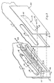
- the present self-loading pistol is preferably approximately rectangular and essentially consists of an upper frame part 2, a corresponding lower frame part 7 and two side walls 3, 4.
- the side walls 3, 4 are preferably screwed to the upper frame part 2 and the lower frame part 7 in the manner shown schematically in FIG. 2 with the aid of suitable screws.
- the barrel 1 with its bore 5 on the inside lower side of the front region of the upper frame part 2, which serves as a barrel holder, is attached.
- the barrel 1 is preferably fastened to the barrel holder 2 with the aid of the dovetail-like projections 22 shown, which engage in corresponding dovetail-like depressions 23, said projections 22 and depressions 23 being provided on the mutually facing sides of the barrel 1 and the barrel holder 2 .
- This type of attachment of the barrel 1 to the barrel holder 2 is particularly advantageous because when assembling the present self-loading pistol the barrel 1, for example after the attachment of a side wall 4 to the barrel holder 2, only in a simple manner from the side facing away from the side wall 4 the barrel holder 2 must be inserted without the need for special and cumbersome fastening operations.
- the magazine receiving opening 6 is determined by the inner surfaces of the barrel 1, the magazine transport device or the front area of the lower frame part 7 and the side walls 3, 4.
- an opening 8 for the magazine control can preferably be provided in at least one of the side walls 3, 4.
- the opening 8 shows how many magazines are located in which layers behind the magazine receiving opening 6.
- the magazine receiving opening 6 ends in the interior of the present self-loading pistol at a magazine contact surface 12, which is preferably formed by a wall or plate extending perpendicular to the side walls 3, 4 and perpendicular to the bore 5 of the barrel 1, which on the Side walls 3, 4 is fastened, for example by screwing.
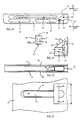
- Each magazine 30 consists of a known box-shaped container in which the individual one above the other Power of the schematically illustrated spring device 30 ⁇ loaded cartridges 30 'are contained, which are fed to the barrel 5 in succession during a shooting operation.
- Each magazine 30 has an end face 42 which is first inserted into the magazine receiving opening 6 and which faces the contact surface 12 during the shooting operation.
- the magazine On the end face 43 opposite the end face 42, the magazine has a guide pin 31 spaced apart from this end face 43, which is fastened at its end remote from the upper magazine end to a pin holding surface 40 such that it is held on the magazine 30 at a distance from the end face 43.
- the pin holding surface 40 is fastened in the upper half of the end surface 43 of the magazine 30 to the end surface 43.
- an angle 33 is attached, which is angled so that it converges to extend the lower edge of the magazine 30.
- a locking notch 32 is formed between the bend 33 and the lower end region of the end face 43, the function of which will be explained in more detail later.
- a locking surface 34 is fastened, which is spaced apart from the end surface 43 of the magazine 30 and preferably parallel to it for a predetermined distance in the direction of the upper end of the magazine 30 runs.
- the pin holding surface 40, the bend 33 and the locking surface 34 preferably represent bends of a material strip 39, which preferably consists of metal and is fastened to the end surface 43 of the magazine 30.
- a locking bend 37 is fastened in the upper half, which has an unspecified through hole into which the guide pin 31 of an adjacent magazine 30 can engage.
- a locking part 36 is fastened to the end face 42, which is spaced and dimensioned from the end face 42 such that it engages in the intermediate space of an adjacent magazine 30, which is opposite the locking face 34, the bend 33 and that of the locking face 4 Area of the metal strip 39 is enclosed.
- the locking bends 37 and the locking part 36 likewise preferably represent bends of a material or metal strip 35, 38 which is fastened to the end face 42 of the magazine 30.
- the bend 37 of the magazine 30 brought into the shooting position engages in a recess in the contact surface 12, so that it is prevented that the magazines 30 can be pulled out of the magazine receiving opening 6 against the direction of the arrow 24.
- the bend preferably engages under 37 a shoulder 86 projecting obliquely downward from the contact surface 12.
- the aforementioned elements 31 to 37 make it possible for several magazines 30 to be non-positively attached to one another, the guide pin 31 of one magazine engaging in the hole of the bend 37 of the other magazine and the locking part 36 between adjacent magazines 30, 30 Locking surface 34 engages when the magazines 30, 30 are aligned with respect to their longitudinal extent. It is thereby achieved that when the first magazine 30 moves in the direction of the arrow 24 (FIG. 3), all subsequent magazines 30 follow this movement. This means that when loading the self-loading pistol, the magazines 30, 30 which are fastened to one another in the manner shown in FIG. 3 are successively inserted into the magazine receiving opening 6 until the foremost or the first inserted magazine 30 with the locking mechanism 37 and the Locking part 36 bears against the contact surface 12.
- the magazines 30 are attached to one another in that the respective front magazine is moved from below in the direction of arrow 44 in such a way that the guide pin 31 of the respective front magazine 30 engages in the hole in the locking bend 37 of the respective subsequent magazine and in that the locking part 36 of the respective subsequent magazine engages behind the locking surface 34 of the respective front magazine.
- the magazine transport device is explained in more detail in connection with FIGS. 1, 4 to 6 and 7 to 11, the function and task of which in particular consists in the magazine located at the front most in the magazine receiving opening 6 along the contact surface 12 to move upwards so that it occupies a position in which the cartridges 30 'of the magazine can be inserted successively through the lock (not shown) of the pistol into the cartridge chamber of barrel 1.
- the magazine transport device is located in the area of the lower frame part 7, which is below the Magazine receiving opening 6 is located between the side walls 3 and 4.
- FIG. 4 which shows a top view of the side of the frame part 7 facing the magazine receiving opening 6, and from the perspective illustration in FIG. 7, which shows the frame part 7, the side walls 3 connected to the frame part 7, 4 and further elements of the magazine transport device 7 in an exploded view
- the longitudinal groove 14 is dimensioned such that a sliding part 16, which emerges in particular from FIGS. 5, 6 and 7, can be slidably mounted in it.
- the sliding part 16 consists essentially of a holding block 25 and a magazine lifting device fastened therein, which preferably has the shape of a leaf spring 20, one end of which is fastened in the holding block 25 in such a way that the lifting spring 20 is in the longitudinal direction of the frame part 7 in the Longitudinal groove 14 extends when the sliding part 16 is inserted into the longitudinal groove 14.
- the upward-facing surface of the holding block 25 is in this state preferably in the plane of the upper surface of the frame part 7.
- the free end 21 of the lifting spring 20 is bent or angled in the direction of the magazine receiving opening 6.
- the lifting spring 20 is preferably fastened between two parts of the holding block 15 in that the parts are screwed together, one end of the lifting spring 20 being located between the parts mentioned.
- the leaf spring 20 is normally supported, if its free end 21 is not raised by the ramp 15, on a support region 28 which is spaced apart from the holding block 25 in the direction of the contact surface 12.
- the support block 28 is preferably fastened to the holding block 25 by a spacer 27 which can slide on the bottom of the longitudinal groove 14.
- the sliding part 16 is displaceable in the longitudinal groove 14 between a first position in which the free end region 21 is raised by the ramp-shaped part 15 and a second position in which the free end region 21 is not raised by the ramp-shaped part 15.
- the sliding part 16 is preferably displaced in the longitudinal groove 14 by at least one between the holding block 25 and the support part 28 above of the spacer 27 and the bolt 57 passed beneath the leaf spring 20, which is guided according to FIG. 7 through an elongate recess 54 of the frame part 7 extending in the longitudinal direction.
- a sliding plate 50, 51, in which the free ends of the bolt 57 are fastened, is preferably provided on each outer side of the side walls 3, 4.
- the sliding part 16 By sliding the sliding plates 50, 51 in the direction of arrow 24 and opposite to this direction, the sliding part 16 can be moved back and forth between the two positions mentioned.
- the bolt 57 runs through the aforementioned recesses (not shown) in the side walls 3, 4.
- opposite side springs 17, 17 are attached when the sliding plates are covered and extend in the longitudinal direction of the longitudinal groove 14 and whose free end regions, which face the ramp 15, are guided inwards by recesses 26, 26 of the side walls 3, 4 running in the longitudinal direction mentioned.
- the ends of the leaf-shaped side springs 17, 17 facing away from the free end region are each fastened to the sliding plates 50, 51, preferably riveted.
- the front ends 18, 18 of the free end regions of the side springs 17, 17 are expediently slightly bent towards one another and can be spread apart such that a magazine 30 is pushed between them in the direction of the arrow 24 can be.
- said ends 18 spring towards each other in such a way that they can snap into the area between the locking surface 34 and an abutment surface 34 'of a magazine 30 and during the movement of the side springs 17, 17 together with the slide plates 50, 51 in the direction of the arrow 24 attack on the abutting surface 34 ', so that the magazine 30 is then moved in the direction of arrow 24.
- the sheet metal strip 39 preferably serves as an abutting surface.
- the ends 18, 18 of the side springs 17, 17 are expediently so high that they bend between the bend 33 and the pin holding surface 40 in the area of the center of the magazines 30 and the middle attack.
- the end positions of the sliding plates 50, 51 are preferably determined in that at least one bolt or the like, which is attached to at least one sliding plate, engages in a further elongated recess in at least one side wall 3 or 4, or through a recess in one of the side walls 3, 4 engages in an elongated further recess of the frame part 7, the said further recesses also each extending in the longitudinal extent of the frame part 7 and wherein one end of the further recess corresponds to a first position and the other end of the further recess corresponds to a second position.
- the magazine transport device is such that when the sliding plates 50, 51 move from the second to the first position, the ends 18, 18, the side springs 17, 17 engage a front magazine in order to transport it to the contact surface 12 and that shortly before reaching the first position, the lifting spring 20 or its end region 21 is raised on the ramp 15 in order to raise the front magazine on the contact surface 12 into the desired position.
- the sliding part 16 or the lifting spring 20 initially remains in the aforementioned position until the pin 57 reaches the holding block 25 from the support block 18, the side springs 17, 17th passed over the following magazine until they spring together and reach behind its abutting surface 34 '.
- the bolt 57 then engages the holding block 25 so that the lifting spring 20 with the sliding part 16 is withdrawn to release the front magazine until the sliding plates 50, 51 reach the second position.
- FIGS. 12 and 14 A further development of the invention can be seen from FIGS. 12 and 14, by which care is taken to ensure that, when the firing of the shot is interrupted and the trigger is already cocked, the magazine from which cartridges are being removed is downward along the contact surface 12 by a predetermined amount Lowering distance is that the cartridge located in front of the retracted lock is lowered from the firing position and the lock can be closed again or moved forward.
- a part 70 having the ramp 15 is provided on the frame part 7 and can be lowered into a lower position from a first, upper position, in which the ramp 15 is arranged so that it can perform the function described.
- the free end 21 of the lifting spring 20 resting on the ramp 15 when the shot is fired is also lowered.
- the part 70 comprising the ramp 15 consists of a block which can be displaced in a recess 77 of the frame part 7 between the upper and the lower position and which has a surface 71 which, during this displacement, runs along a sliding surface 72 of the frame part 7 which is parallel to the contact surface 12 runs and the recess 77 delimits on the side facing away from the contact surface 12, slides.
- the recess 77 is delimited by walls 78, 79 of the frame part 7 projecting over the sliding surface 72, between which the part 70 can slide.
- the said block has a bore 73 in which a coil spring 74 'is arranged, which tries to push the part 70 away from the sliding surface 72.
- part 14 there is also a through groove 74 running parallel to the sliding surface 12, into which two transverse grooves 75, 76 open, which are spaced apart.
- pins 80, 81 extend between the walls 78, 79 and pass through the transverse grooves 75, 76.
- the pins 80, 81 bear against the ends of the transverse grooves 75, 76.
- the part 70 is moved against the force of the spring 74 ′ until it bears on the sliding surface 72.
- the pins 80, 81 are aligned with the through groove 74 so that the part 70 can be moved along the sliding surface 72 to the lower position in which the uppermost pin 80 abuts the upper end of the through groove 74.
- This is dimensioned such that its upper end ends above the groove 75 and its lower end at the lower edge of the groove 76.
- the locking springs 82 are in the form of leaf springs which are fastened to the inner surfaces of the side walls 3, 4 in such a way that their free ends 83, which project resiliently into the space between the side walls 3, 4, are supported on said magazine and this hold against the designated movement.
- the ends 83 are pressed apart resiliently so that the magazine can pass between the ends 83.
- the ends 83 spring inward behind the magazine in order to abut against it.
- FIG. 16 shows an embodiment of the invention in which the ends of the side springs 17 which protrude through the recesses 26 of the side walls 3, 4 and which are fastened to the sliding plates 50 and 51 are designed in such a way that they point upwards and / or regions 84, 85 projecting below which run perpendicular to the longitudinal extent of the side springs 17. It is thereby achieved that the free end edges of the areas 84, 85 engage the magazines over a relatively large length L for transporting them.
Landscapes
- Engineering & Computer Science (AREA)
- General Engineering & Computer Science (AREA)
- Portable Nailing Machines And Staplers (AREA)
- Toys (AREA)
- Vending Machines For Individual Products (AREA)
- Testing Of Coins (AREA)
- Automatic Focus Adjustment (AREA)
- Control And Other Processes For Unpacking Of Materials (AREA)
Priority Applications (1)
| Application Number | Priority Date | Filing Date | Title |
|---|---|---|---|
| AT88107635T ATE97229T1 (de) | 1987-05-13 | 1988-05-11 | Selbstladepistole. |
Applications Claiming Priority (2)
| Application Number | Priority Date | Filing Date | Title |
|---|---|---|---|
| DE3716009 | 1987-05-13 | ||
| DE19873716009 DE3716009A1 (de) | 1987-05-13 | 1987-05-13 | Selbstladepistole |
Publications (3)
| Publication Number | Publication Date |
|---|---|
| EP0291054A2 EP0291054A2 (de) | 1988-11-17 |
| EP0291054A3 EP0291054A3 (en) | 1989-11-15 |
| EP0291054B1 true EP0291054B1 (de) | 1993-11-10 |
Family
ID=6327465
Family Applications (1)
| Application Number | Title | Priority Date | Filing Date |
|---|---|---|---|
| EP88107635A Expired - Lifetime EP0291054B1 (de) | 1987-05-13 | 1988-05-11 | Selbstladepistole |
Country Status (4)
| Country | Link |
|---|---|
| US (1) | US4947571A (enExample) |
| EP (1) | EP0291054B1 (enExample) |
| AT (1) | ATE97229T1 (enExample) |
| DE (2) | DE3716009A1 (enExample) |
Families Citing this family (3)
| Publication number | Priority date | Publication date | Assignee | Title |
|---|---|---|---|---|
| US5299373A (en) * | 1989-11-24 | 1994-04-05 | Sandor Breiner | Hand-gun with moving cartridge chamber magazine |
| US20100212483A1 (en) * | 2007-04-24 | 2010-08-26 | Steve Hines | M240 adapter assembly clip |
| WO2015095295A1 (en) * | 2013-12-19 | 2015-06-25 | Torrent Loading Systems, LLC | Magazine dispenser |
Family Cites Families (14)
| Publication number | Priority date | Publication date | Assignee | Title |
|---|---|---|---|---|
| US45105A (en) * | 1864-11-15 | Improvement in self-loading fire-arms | ||
| US896453A (en) * | 1907-12-10 | 1908-08-18 | St Omer Mangle | Automatic firearm. |
| DE235250C (enExample) * | 1910-01-15 | |||
| US1453439A (en) * | 1921-03-21 | 1923-05-01 | C E Reed | Recoil-operated firearm |
| US2130383A (en) * | 1934-01-25 | 1938-09-20 | Sig Schweiz Industrieges | Automatic firearm |
| US2130722A (en) * | 1934-12-11 | 1938-09-20 | Lisle M Weaver | Magazine for machine gun pistols |
| BE429728A (enExample) * | 1937-08-19 | |||
| US2289067A (en) * | 1941-08-28 | 1942-07-07 | High Standard Mfg Corp | Box-magazine for firearms |
| US2345031A (en) * | 1942-03-03 | 1944-03-28 | James H Carithers | Multiple clip magazine for rifles |
| CH369384A (de) * | 1958-12-02 | 1963-05-15 | Tschumi Ernst | Automatische Handfeuerwaffe zur Abgabe von Einzel- oder Seriefeuer |
| US3177601A (en) * | 1963-12-18 | 1965-04-13 | Meunier Robert | Bolt stop for use with tandem-type magazines |
| US4447976A (en) * | 1982-05-17 | 1984-05-15 | Cooper Ladreau V | Cartridge magazine mount |
| US4484404A (en) * | 1982-09-13 | 1984-11-27 | J.F.S., Inc. | Spare magazine holder |
| DE3307083A1 (de) * | 1983-03-01 | 1984-09-06 | EM-GE Sportgeräte GmbH & Co KG, 7929 Gussenstadt | Signalpistole |
-
1987
- 1987-05-13 DE DE19873716009 patent/DE3716009A1/de active Granted
-
1988
- 1988-05-11 DE DE88107635T patent/DE3885506D1/de not_active Expired - Fee Related
- 1988-05-11 AT AT88107635T patent/ATE97229T1/de not_active IP Right Cessation
- 1988-05-11 EP EP88107635A patent/EP0291054B1/de not_active Expired - Lifetime
- 1988-05-13 US US07/193,709 patent/US4947571A/en not_active Expired - Fee Related
Also Published As
| Publication number | Publication date |
|---|---|
| EP0291054A3 (en) | 1989-11-15 |
| DE3885506D1 (de) | 1993-12-16 |
| DE3716009C2 (enExample) | 1991-06-13 |
| US4947571A (en) | 1990-08-14 |
| ATE97229T1 (de) | 1993-11-15 |
| EP0291054A2 (de) | 1988-11-17 |
| DE3716009A1 (de) | 1988-12-01 |
Similar Documents
| Publication | Publication Date | Title |
|---|---|---|
| EP1265049B1 (de) | Magazin für luftdruckwaffengeschosse und behälter zum lagern von geschossen für ein solches magazin | |
| EP1147359B1 (de) | Verschlussvorrichtung für eine handfeuerwaffe | |
| DE2051411C3 (de) | Verschlußeinrichtung für eine Trommelwaffe | |
| DE10296851T5 (de) | Patronenkammersystem für Schusswaffen | |
| DE3243241A1 (de) | Wechsellauf fuer faustfeuerwaffen | |
| DE2413615B2 (de) | Handfeuerwaffe mit schwenkbarem Verschlußteil | |
| DE1578392C3 (de) | Halbstarr verriegelter Verschluß für automatische Feuerwaffen | |
| DE2125149B2 (de) | Waffe | |
| DE1919245C3 (de) | Brennkraftbolzensetzer | |
| DE69407368T2 (de) | Magazin formende Munition zum Verschiessen elektromagnetischer Düppel | |
| DE2751042C2 (de) | Gasdruckladeeinrichtung für eine selbstladende Schußwaffe | |
| DE1478871A1 (de) | Bolzensetzpistole mit wiederholter Schussabgabe | |
| EP0291054B1 (de) | Selbstladepistole | |
| EP1379827B1 (de) | Vorrichtung zum entfernen von patronen und/oder patronenhülsen in einer kipplaufwaffe | |
| AT17578U1 (de) | Pfeilzuführvorrichtung für eine armbrust | |
| EP0123059B1 (de) | Signalpistole | |
| DE2429751C3 (de) | Selbstladesportpistole | |
| DE3825768C3 (de) | Druckgasbetätigte Schußwaffe | |
| WO1989012796A2 (en) | Firearm | |
| DE2040624C2 (de) | Infanteriewaffe mit mehreren Waffenrohren zum gleichzeitigen Abfeuern mehrerer Schüsse | |
| EP3581873B1 (de) | Gewehrlauf mit integrierter patronenführung und repetiergewehr mit einem derartigen gewehrlauf | |
| DE3141929C2 (de) | Spielzeugschußwaffe | |
| DE3126291C2 (de) | Schnellfeuergewehr | |
| DE809154C (de) | Repetierfeuerwaffe | |
| DE555759C (de) | Einrichtung an Mannlicher-Gewehren zur Verfeuerung von randlosen Patronen, z. B. nach System Mauser |
Legal Events
| Date | Code | Title | Description |
|---|---|---|---|
| PUAI | Public reference made under article 153(3) epc to a published international application that has entered the european phase |
Free format text: ORIGINAL CODE: 0009012 |
|
| AK | Designated contracting states |
Kind code of ref document: A2 Designated state(s): AT BE CH DE ES FR GB IT LI |
|
| PUAL | Search report despatched |
Free format text: ORIGINAL CODE: 0009013 |
|
| AK | Designated contracting states |
Kind code of ref document: A3 Designated state(s): AT BE CH DE ES FR GB IT LI |
|
| 17P | Request for examination filed |
Effective date: 19900322 |
|
| 17Q | First examination report despatched |
Effective date: 19910930 |
|
| GRAA | (expected) grant |
Free format text: ORIGINAL CODE: 0009210 |
|
| AK | Designated contracting states |
Kind code of ref document: B1 Designated state(s): AT BE CH DE ES FR GB IT LI |
|
| PG25 | Lapsed in a contracting state [announced via postgrant information from national office to epo] |
Ref country code: GB Effective date: 19931110 Ref country code: ES Free format text: THE PATENT HAS BEEN ANNULLED BY A DECISION OF A NATIONAL AUTHORITY Effective date: 19931110 Ref country code: BE Effective date: 19931110 Ref country code: IT Free format text: LAPSE BECAUSE OF FAILURE TO SUBMIT A TRANSLATION OF THE DESCRIPTION OR TO PAY THE FEE WITHIN THE PRE;WARNING: LAPSES OF ITALIAN PATENTS WITH EFFECTIVE DATE BEFORE 2007 MAY HAVE OCCURRED AT ANY TIME BEFORE 2007. THE CORRECT EFFECTIVE DATE MAY BE DIFFERENT FROM THE ONE RECORDED.SCRIBED TIME-LIMIT Effective date: 19931110 |
|
| REF | Corresponds to: |
Ref document number: 97229 Country of ref document: AT Date of ref document: 19931115 Kind code of ref document: T |
|
| REF | Corresponds to: |
Ref document number: 3885506 Country of ref document: DE Date of ref document: 19931216 |
|
| ET | Fr: translation filed | ||
| PG25 | Lapsed in a contracting state [announced via postgrant information from national office to epo] |
Ref country code: AT Effective date: 19940511 |
|
| GBV | Gb: ep patent (uk) treated as always having been void in accordance with gb section 77(7)/1977 [no translation filed] |
Effective date: 19931110 |
|
| PLBE | No opposition filed within time limit |
Free format text: ORIGINAL CODE: 0009261 |
|
| STAA | Information on the status of an ep patent application or granted ep patent |
Free format text: STATUS: NO OPPOSITION FILED WITHIN TIME LIMIT |
|
| 26N | No opposition filed | ||
| PGFP | Annual fee paid to national office [announced via postgrant information from national office to epo] |
Ref country code: FR Payment date: 19950517 Year of fee payment: 8 |
|
| PGFP | Annual fee paid to national office [announced via postgrant information from national office to epo] |
Ref country code: CH Payment date: 19950519 Year of fee payment: 8 |
|
| PGFP | Annual fee paid to national office [announced via postgrant information from national office to epo] |
Ref country code: DE Payment date: 19950718 Year of fee payment: 8 |
|
| PG25 | Lapsed in a contracting state [announced via postgrant information from national office to epo] |
Ref country code: CH Effective date: 19960531 Ref country code: LI Effective date: 19960531 |
|
| REG | Reference to a national code |
Ref country code: CH Ref legal event code: PL |
|
| PG25 | Lapsed in a contracting state [announced via postgrant information from national office to epo] |
Ref country code: FR Effective date: 19970131 |
|
| PG25 | Lapsed in a contracting state [announced via postgrant information from national office to epo] |
Ref country code: DE Effective date: 19970201 |
|
| REG | Reference to a national code |
Ref country code: FR Ref legal event code: ST |