EP0286982A2 - Dispositif de mise en registre - Google Patents
Dispositif de mise en registre Download PDFInfo
- Publication number
- EP0286982A2 EP0286982A2 EP88105590A EP88105590A EP0286982A2 EP 0286982 A2 EP0286982 A2 EP 0286982A2 EP 88105590 A EP88105590 A EP 88105590A EP 88105590 A EP88105590 A EP 88105590A EP 0286982 A2 EP0286982 A2 EP 0286982A2
- Authority
- EP
- European Patent Office
- Prior art keywords
- register
- cylinder
- cylinders
- plate
- plate cylinder
- Prior art date
- Legal status (The legal status is an assumption and is not a legal conclusion. Google has not performed a legal analysis and makes no representation as to the accuracy of the status listed.)
- Granted
Links
- 238000007639 printing Methods 0.000 claims description 23
- 238000006073 displacement reaction Methods 0.000 claims description 13
- 230000002093 peripheral effect Effects 0.000 claims description 4
- 238000000034 method Methods 0.000 description 4
- 238000010586 diagram Methods 0.000 description 2
- 239000003086 colorant Substances 0.000 description 1
- 230000008878 coupling Effects 0.000 description 1
- 238000010168 coupling process Methods 0.000 description 1
- 238000005859 coupling reaction Methods 0.000 description 1
- 238000011161 development Methods 0.000 description 1
- 230000018109 developmental process Effects 0.000 description 1
- 230000000694 effects Effects 0.000 description 1
- 238000007645 offset printing Methods 0.000 description 1
- 230000000717 retained effect Effects 0.000 description 1
Images

Classifications
-
- B—PERFORMING OPERATIONS; TRANSPORTING
- B41—PRINTING; LINING MACHINES; TYPEWRITERS; STAMPS
- B41F—PRINTING MACHINES OR PRESSES
- B41F33/00—Indicating, counting, warning, control or safety devices
-
- B—PERFORMING OPERATIONS; TRANSPORTING
- B41—PRINTING; LINING MACHINES; TYPEWRITERS; STAMPS
- B41F—PRINTING MACHINES OR PRESSES
- B41F13/00—Common details of rotary presses or machines
- B41F13/08—Cylinders
- B41F13/10—Forme cylinders
- B41F13/12—Registering devices
- B41F13/14—Registering devices with means for displacing the cylinders
Definitions
- the invention relates to a register setting device for a printing unit with three approximately Y-shaped, plate / blanket cylinder pairs comprising printing units, which have helical gear wheels on their axes, two of which are designed as double gears with opposite pitch on the journal of two rubber blanket cylinders and via a gear are in permanent tooth engagement with one another on the journal of the third rubber blanket cylinder, all cylinders being axially displaceable and the drive being initiated via a gearwheel arranged on a cylinder.
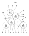
- a printing unit which preferably comprises three approximately Y-shaped printing units 1, 2, 3.
- a blanket cylinder 4 and a plate cylinder 5 are provided
- a blanket cylinder 6 and a plate cylinder 7 and in the printing unit 3 a blanket cylinder 8 and a plate cylinder 9 are provided.
- the cylinders 5 to 9 each have axle journals mounted on both sides in side walls 20, as is indicated for the cylinders 4, 5, 7, 8, 9 by the reference numerals 10 to 14.
- a printing carrier web 69 can preferably be provided with a double face print and an impression by the offset printing method.
- a print carrier web can be provided with four times face printing and double back pressure.
- the basic setting is similar to that described below.
- a triple face print ie a three-color print, can be applied in full use of the principle on which the invention is based, with the advantageous setting and readjustment of the side and circumferential register according to the invention having a particular effect for each color.
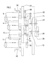
- Fig. 2 shows the cylinders 4, 5, 6, 7 mounted in a side wall 20 with their axle journals 10, 11, 12, 21.
- the cylinders 5 to 9 are driven by means of helical toothed drive gears 22 to 29, wherein in the example shown here in advantageously, the drive of a helical gear 68 is firmly connected to the gear 22 on the journal 11 of the cylinder 5.
- On the journal 10 of the blanket cylinder 4 sits a double gear 23, 24, which drives the gear 26 on the journal 12 of the plate cylinder 7 via a gear 25 on the journal 21 of the rubber blanket cylinder 6.
- a further printing unit 3 with the cylinders 8, 9 can be arranged above the printing units 1 and 2.
- the plate cylinder 9 of the printing unit 3 is driven via the gear 27 arranged on its journal 14, which meshes with a double gear 28, 29 on the journal 13 of the blanket cylinder 8.
- the gear 29 is in engagement with the gear 25 of the blanket cylinder 6.
- the drive is shown side by side for reasons of clarity, while in practice it is in two planes, i.e. is arranged one above the other.
- the gears 27, 28 thus lie in the plane of the gears 22, 23 and the gear 29 in the plane of the gears 24, 25, 26.
- the cylinders 4, 5, 7, 8, 9 are each provided with a register actuating device, preferably in the form of a register actuating motor, as indicated at 15, 16, 17, 18, 19. With the register actuators 15 to 19, the cylinders 4, 5, 7, 8, 9 can be axially displaced. According to the invention, therefore, a blanket cylinder, here the blanket cylinder 6, is not provided with a register actuating device, ie with a register actuating motor. In the context of the invention, it is advantageous to initiate the drive, preferably in the form of a gear 68 on the printing unit 1, ie to bring the drive gear 68 into engagement with the gear 22 of the plate cylinder 5.
- the register setting device comprises 15 to 19 position locking devices, for example linear potentiometers, with the aid of which the lateral position of the cylinders 4, 5, 7, 8, 9 can be determined in each case.
- a position locking device 30 is thus assigned to the plate cylinder 5 directly or to the register actuator 16 assigned to it.
- the blanket cylinder 4 to which or its servomotor 15 a position locking device 33 is assigned, while the plate cylinder 9 or its register servomotor 19 is assigned a position locking device 40.
- the cylinders 7 and 8 and their register actuators 17 and 18 are equipped with position locking devices 43 and 62, respectively.
- the motors 16, 17, 19 are connected to switches 32, 42, 64.
- two position regulators 34, 44 are used in the register actuating device according to the invention, of which the position regulator 34 can control the servomotor 15 and the position regulator 44 can actuate the servomotor 18.
- the position controllers 34, 44 are connected to the Position locking devices 30, 40, 62 connected.
- the position controller 34 receives information via the position locking device 30, ie an electrical signal that provides information about the position of the servomotor 16 or the axial position of the plate cylinder 5, and information about the position of the rubber cylinder 4 via the locking device 33. as at 65 or for the indicated on the cylinders at 66 and 67 due to the helical drive, there is a mechanical or positive connection between the cylinders 4 and 5.
- the plate cylinder 5 when the plate cylinder 5 is axially displaced, the latter rotates and, since the drive gear 68 does not rotate, the rotation of the plate cylinder 5 as a result of its axial displacement via the gear 22 causes a change in the circumferential register.
- the axial position of the plate cylinder 5 is displayed via the position locking device 30 on the display instrument 31 and the axial position of the blanket cylinder 4 on the display instrument 35. If the plate cylinder 5 now rotates due to axial displacement, this is communicated to the position controller 34 by the position locking device 30, which in the same Directs an axial displacement via the actuator 15 for the blanket cylinder 4, so that the rotation of the plate cylinder 5 is compensated.
- a side register adjustment of the plate cylinder 5 is possible, which automatically results in a compensation of the change in the circumferential register caused thereby.
- a servomotor 37 which together with the potentiometer 36 constitutes a so-called motor potentiometer, activates the position controller 34 by actuating a switch 38, so that the register servomotor 15 is activated correspondingly axially moves the blanket cylinder 4.
- the side register of the plate cylinder 7 is carried out according to the invention by its axial displacement by means of the register servomotor 17.
- the resulting rotation can now only affect the plate cylinder 9 via the cylinders 6 and 8, ie the circumferential setting of the plate cylinder 5 is no longer changed.
- the side register of the plate cylinder 9 is now set thirdly by means of its axial displacement, this only results in a rotation of the circumference of the plate cylinder 9. This also means that the circumference of the plate cylinder 5 is no longer changed.
- the influence on the plate cylinder 7 is compensated.
- the side register of the plate register 5 then the side register of the plate cylinder 7 and then the side register of the plate cylinder 9 are set.
- the plate cylinder 5 is held circumferentially as a result of the drive gear 68
- compensation for the circumferential register setting or a later correction of the side register settings of the plate cylinders 5, 7, 9 results in a compensation according to the invention in that circumferential displacement of the blanket cylinder 4 the plate cylinders 7 and 9 adjustable on the circumference of the plate cylinder 5, that is. are readjustable.
- the circumferential register of the plate cylinder 9 differs, compensation or adjustment is carried out in that the blanket cylinder 8 is axially displaced.
- the rotation of the plate cylinder 7 takes place by the axial displacement of the blanket cylinder 4, which, as already mentioned, the plate cylinder 5 can not rotate, so that by its shift caused rotation itself affects only as a rotation of the plate cylinder 7 and a rotation of the plate cylinder 9 also does not take place, since the blanket cylinder 8 is pushed in the same axial direction as the blanket cylinder 4, so that the axial displacement of the blanket cylinder 4 for adjusting the circumferential register of the plate cylinder 7 does not affect the circumferential register of the plate cylinder 9 affects.
- the setting of the peripheral register of the plate cylinder 5 is shown in FIG. 3, while the setting of the peripheral register of the plate cylinder 9 is shown in FIG. 4. 4, the side position of the plate cylinder 9 is again detected by means of the associated position locking element 40, the value of which is displayed on the instrument 41.
- a displacement of the plate cylinder 9 or the associated register servomotor 19 is communicated via the position fixing device 40, which communicates this value, which is also indicated at 41, to the position controller 44.
- the peripheral register of the plate cylinder 9 is set by the position controller 44 via the register servomotor 18 or the rubber blanket cylinder 8.
- the setpoint value for the circumferential register of the plate cylinder 9 can be adjusted by the potentiometer 46, a desired circumferential register value on the plate cylinder 9 being adjustable by actuating the switch 48 and thus the servomotor 47.
- both position controllers 34, 44 must be activated, which was indicated by the switch 49, if the circumferential register of the plate cylinder 7 is to be set, since, as has already been described above, the blanket cylinders 4 and 8 are axially displaced in this case Need to become. It is therefore sufficient to use only two position controllers 34, 44 for the circumferential register setting of the plate cylinders 5, 7, 9, which are activated individually according to FIGS. 3 and 4 for the circumferential register setting of the plate cylinders 5 and 9, while they are activated together must if the circumferential register of the plate cylinder 7 is to be set according to FIG.
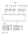
- FIG. 6 which comprises a microcomputer or microprocessor 50
- All actual values of the five cylinders are shown to it by the position locking devices 30, 62, 40; 33, 43 forwarded.
- the microprocessor 50 processes the target and actual values in accordance with the preceding descriptions and outputs the actuating signals to the register actuators 15 to 19 in the manner described above.
- For the compensation of the circumferential register due to the side register adjustment there is also a shift of the blanket cylinder 4 for the plate cylinder 5 of the blanket cylinder 8 for the blanket cylinder 9 and the blanket cylinder 4 and 8 for the plate cylinder 7.
- the circumferential register adjustment of the cylinders 5, 7, 9 can be described in FIG This is done in such a way that the circumferential register of the plate cylinder 5 by shifting the blanket cylinder 4, the circumferential register of the plate cylinder 7 by shifting the blanket cylinder 4 together with the blanket cylinder 8 and the setting of the circumferential register of the plate cylinder 9 by shifting the blanket cylinder 8.
- an operating keyboard 54 is connected to the microprocessor.
- This can advantageously have three buttons 55, 56, 57 for the three colors to be printed on one side of the print carrier web 69. If, for example, the first color is to be set in terms of the side and circumference registers, the button 55 is actuated, after which the circumferential registers on the corresponding plate cylinder in the forward and backward direction by means of Keys 60, 61 and the side register, that is adjustable in the left and right directions by means of the buttons 58, 59.
- the drive i.e. to introduce the drive gear 68 via the drive gear of the plate cylinder 7 or 9, only the setting sequence changing, which can be determined by simple considerations taking into account the preceding description.
- the drive can be introduced via the blanket cylinder 6 or in each case via the blanket cylinder, which has only a simple, that is to say no, double gear, although it is somewhat disadvantageous that in this case the blanket cylinders 4, 6, 8 are separated when they are switched off certain problems can occur from each other due to the drive.
Landscapes
- Engineering & Computer Science (AREA)
- Mechanical Engineering (AREA)
- Inking, Control Or Cleaning Of Printing Machines (AREA)
- Rotary Presses (AREA)
- Registering Or Overturning Sheets (AREA)
Applications Claiming Priority (2)
| Application Number | Priority Date | Filing Date | Title |
|---|---|---|---|
| DE3712702 | 1987-04-14 | ||
| DE19873712702 DE3712702A1 (de) | 1987-04-14 | 1987-04-14 | Registerstellvorrichtung |
Publications (3)
| Publication Number | Publication Date |
|---|---|
| EP0286982A2 true EP0286982A2 (fr) | 1988-10-19 |
| EP0286982A3 EP0286982A3 (en) | 1989-11-29 |
| EP0286982B1 EP0286982B1 (fr) | 1992-06-10 |
Family
ID=6325635
Family Applications (1)
| Application Number | Title | Priority Date | Filing Date |
|---|---|---|---|
| EP88105590A Expired - Lifetime EP0286982B1 (fr) | 1987-04-14 | 1988-04-08 | Dispositif de mise en registre |
Country Status (4)
| Country | Link |
|---|---|
| US (1) | US4821640A (fr) |
| EP (1) | EP0286982B1 (fr) |
| JP (1) | JPS63264355A (fr) |
| DE (2) | DE3712702A1 (fr) |
Cited By (3)
| Publication number | Priority date | Publication date | Assignee | Title |
|---|---|---|---|---|
| DE3933666A1 (de) * | 1989-10-09 | 1991-04-18 | Heidelberger Druckmasch Ag | Vorrichtung und verfahren zur registerverstellung an einer druckmaschine mit mehreren druckwerken |
| DE4038510A1 (de) * | 1990-12-03 | 1992-06-04 | Roland Man Druckmasch | Registerstellvorrichtung |
| NL2001608C2 (nl) * | 2008-05-22 | 2009-11-24 | Mps Holding B V | Drukmodule voor gebruik in een offsetdrukinrichting en offsetdrukinrichting voorzien van een dergelijke drukmodule. |
Families Citing this family (17)
| Publication number | Priority date | Publication date | Assignee | Title |
|---|---|---|---|---|
| DE3918127C1 (fr) * | 1989-06-03 | 1990-12-13 | Man Roland Druckmaschinen Ag, 6050 Offenbach, De | |
| DE4021895C2 (de) * | 1990-07-10 | 1994-02-17 | Roland Man Druckmasch | Druckeinheit einer Offsetdruckmaschine zur Durchführung eines fliegenden Druckplattenwechsels |
| DE4110035C2 (de) * | 1991-03-27 | 1995-04-13 | Roland Man Druckmasch | Vorrichtung zum Verstellen von Elementen in Falzwerkzylindern von Rotationsdruckmaschinen |
| EP0652104B1 (fr) * | 1993-11-05 | 2002-04-10 | MAN Roland Druckmaschinen AG | Unité d'impression pour impression offset sans eau de mouillage |
| US6644184B1 (en) | 1995-02-09 | 2003-11-11 | Man Roland Druckmaschinen Ag | Offset printing machine |
| DE4430693B4 (de) * | 1994-08-30 | 2005-12-22 | Man Roland Druckmaschinen Ag | Antriebe für eine Rollenrotations-Offsetdruckmaschine |
| US5668455A (en) * | 1994-09-16 | 1997-09-16 | Gotz; Fritz Rainer | Angle encoder for rotating equipment |
| DE19508517A1 (de) * | 1995-03-10 | 1996-09-12 | Roland Man Druckmasch | Registereinstellvorrichtung |
| DE19508516A1 (de) * | 1995-03-10 | 1996-09-12 | Roland Man Druckmasch | Registereinstellvorrichtung |
| DE10119140A1 (de) * | 2000-05-17 | 2001-11-22 | Heidelberger Druckmasch Ag | Bedruckstoffbögen verarbeitende Maschine |
| DE10164651A1 (de) | 2001-04-17 | 2002-10-31 | Koenig & Bauer Ag | Verfahren und Vorrichtung zur Registerregelung |
| DE10118759A1 (de) * | 2001-04-17 | 2002-11-07 | Koenig & Bauer Ag | Verfahren und Vorrichtung zur Registerregelung |
| KR100501959B1 (ko) * | 2003-02-06 | 2005-07-20 | 조충 | 윤전기구조 |
| EP1593504A1 (fr) * | 2004-05-04 | 2005-11-09 | Müller Martini Holding AG | Dispositif avec bâti et unité d'application d'un revêtement relié à ce dernier |
| DE102005019566A1 (de) * | 2005-04-27 | 2006-11-09 | Bosch Rexroth Aktiengesellschaft | Druckmaschine und Verfahren zur Registerkorrektur |
| DE102018201968A1 (de) * | 2017-03-08 | 2018-09-13 | Heidelberger Druckmaschinen Ag | Verfahren zur Reduktion von quasi-statischen Passerdifferenzen in einer Druckmaschine |
| CN109501440B (zh) * | 2018-09-28 | 2020-09-18 | 陕西北人印刷机械有限责任公司 | 一种版辊驱动及横向自动对版装置 |
Citations (2)
| Publication number | Priority date | Publication date | Assignee | Title |
|---|---|---|---|---|
| WO1983004219A1 (fr) * | 1982-06-01 | 1983-12-08 | Web Printing Controls Co., Inc. | Systeme de commande de registre |
| EP0154836A2 (fr) * | 1984-03-14 | 1985-09-18 | Heidelberger Druckmaschinen Aktiengesellschaft | Dispositif de répérage pour rotatives d'impression |
Family Cites Families (6)
| Publication number | Priority date | Publication date | Assignee | Title |
|---|---|---|---|---|
| US4222325A (en) * | 1978-08-25 | 1980-09-16 | White Consolidated Industries, Inc. | Mounting means for movable carriage on an offset press |
| SE426153B (sv) * | 1979-01-22 | 1982-12-13 | Wifag Maschf | Drivanordning for en valsrotations offsettryckmaskin |
| US4572074A (en) * | 1984-11-14 | 1986-02-25 | Harris Graphics Corporation | Multi-unit press register |
| DD235049A1 (de) * | 1985-03-04 | 1986-04-23 | Polygraph Leipzig | Steuerschaltung |
| DD235050B1 (de) * | 1985-03-04 | 1988-09-21 | Polygraph Leipzig | Steuerschaltung |
| DE3614029C1 (de) * | 1986-04-25 | 1987-04-02 | Roland Man Druckmasch | Rollenrotations-Offsetdruckmaschine mit einem Druckwerk fuer fliegenden Plattenwechsel |
-
1987
- 1987-04-14 DE DE19873712702 patent/DE3712702A1/de not_active Ceased
-
1988
- 1988-04-08 EP EP88105590A patent/EP0286982B1/fr not_active Expired - Lifetime
- 1988-04-08 DE DE8888105590T patent/DE3871845D1/de not_active Expired - Lifetime
- 1988-04-13 JP JP63089174A patent/JPS63264355A/ja active Pending
- 1988-04-13 US US07/181,310 patent/US4821640A/en not_active Expired - Fee Related
Patent Citations (2)
| Publication number | Priority date | Publication date | Assignee | Title |
|---|---|---|---|---|
| WO1983004219A1 (fr) * | 1982-06-01 | 1983-12-08 | Web Printing Controls Co., Inc. | Systeme de commande de registre |
| EP0154836A2 (fr) * | 1984-03-14 | 1985-09-18 | Heidelberger Druckmaschinen Aktiengesellschaft | Dispositif de répérage pour rotatives d'impression |
Cited By (5)
| Publication number | Priority date | Publication date | Assignee | Title |
|---|---|---|---|---|
| DE3933666A1 (de) * | 1989-10-09 | 1991-04-18 | Heidelberger Druckmasch Ag | Vorrichtung und verfahren zur registerverstellung an einer druckmaschine mit mehreren druckwerken |
| US5327826A (en) * | 1989-10-09 | 1994-07-12 | Heidelberger Druckmaschinen Ag | Register adjustment device on a printing machine with a plurality of printing units and method of operating the device |
| DE4038510A1 (de) * | 1990-12-03 | 1992-06-04 | Roland Man Druckmasch | Registerstellvorrichtung |
| NL2001608C2 (nl) * | 2008-05-22 | 2009-11-24 | Mps Holding B V | Drukmodule voor gebruik in een offsetdrukinrichting en offsetdrukinrichting voorzien van een dergelijke drukmodule. |
| WO2009142495A1 (fr) * | 2008-05-22 | 2009-11-26 | Mps Holding B.V. | Module d’impression destiné à être utilisé dans un appareil d’impression offset et appareil d’impression offset muni d’un tel module d’impression |
Also Published As
| Publication number | Publication date |
|---|---|
| EP0286982A3 (en) | 1989-11-29 |
| JPS63264355A (ja) | 1988-11-01 |
| EP0286982B1 (fr) | 1992-06-10 |
| DE3712702A1 (de) | 1988-11-03 |
| US4821640A (en) | 1989-04-18 |
| DE3871845D1 (de) | 1992-07-16 |
Similar Documents
| Publication | Publication Date | Title |
|---|---|---|
| EP0286982B1 (fr) | Dispositif de mise en registre | |
| DE3435487C2 (fr) | ||
| DE2818662C2 (de) | Vorrichtung zum Einstellen des Seiten- und Umfangsregisters eines Plattenzylinders einer Rotationsdruckmaschine | |
| EP0154836B1 (fr) | Dispositif de répérage pour rotatives d'impression | |
| EP0531675B1 (fr) | Procédé et dispositif pour régler les vis des zones d'encrage dans leurs positions respectives | |
| DE3432572A1 (de) | Rotationsdruckpresse | |
| DE3743646C2 (de) | Vorrichtung zum Einstellen einer in einer Druckmaschine zugeführten Druckfarbmenge | |
| EP1243414A1 (fr) | Méthode d'impression | |
| DE3045611C2 (de) | Registerstelleinrichtung einer Bogen-Rotationsoffsetdruckmaschine für gleichzeitigen Schön- und Widerdruck | |
| EP1291175B1 (fr) | Cylindre porte-plaque pour plusieurs images | |
| DE3917919C2 (fr) | ||
| DE3504435A1 (de) | Bogen-druckmaschine mit bogenanlage an einem druckmaschinen-zylinder | |
| EP0705689B2 (fr) | Entraínement pour une machine à imprimer des feuilles en plusieurs couleurs | |
| DE3336792C2 (fr) | ||
| DE2609513B2 (de) | Vorrichtung zum An- und Abstellen eines auf den Formzylinder einer Tiefdruckmaschine wirkenden Presseurs | |
| DE3620152C2 (de) | Schaltungsanordnung für ein Offsetdruckmaschinen-Farbwerkverstellsystem | |
| EP0196019A2 (fr) | Machine à imprimer rotative offset à bobines avec un mécanisme d'impression pour changement de plaques volant | |
| DE4219147C5 (de) | Umfangsregistereinstellvorrichtung für eine Offset-Druckmaschine | |
| DE2364858C3 (de) | Mechanisches Steuerelement mit Speichermöglichkeit ausgewählter Einstellpositionen | |
| DE3832891A1 (de) | Offset-druckmaschine zum drucken einer kontinuierlichen bahn | |
| DE4038510A1 (de) | Registerstellvorrichtung | |
| DE4436584C2 (de) | Plattenzylinderlagerung | |
| DE3246938A1 (de) | Druckmaschine mir druckplattenzylinder, farbauftragwalze und gegendruckzylinder | |
| DE3224649C2 (fr) | ||
| DE2926765A1 (de) | Vorrichtung zur unterdrueckung von biegeschwingungen in rotations-offsetdruckmaschinen |
Legal Events
| Date | Code | Title | Description |
|---|---|---|---|
| PUAI | Public reference made under article 153(3) epc to a published international application that has entered the european phase |
Free format text: ORIGINAL CODE: 0009012 |
|
| AK | Designated contracting states |
Kind code of ref document: A2 Designated state(s): CH DE FR IT LI SE |
|
| PUAL | Search report despatched |
Free format text: ORIGINAL CODE: 0009013 |
|
| AK | Designated contracting states |
Kind code of ref document: A3 Designated state(s): CH DE FR IT LI SE |
|
| 17P | Request for examination filed |
Effective date: 19891028 |
|
| 17Q | First examination report despatched |
Effective date: 19910325 |
|
| ITF | It: translation for a ep patent filed | ||
| GRAA | (expected) grant |
Free format text: ORIGINAL CODE: 0009210 |
|
| AK | Designated contracting states |
Kind code of ref document: B1 Designated state(s): CH DE FR IT LI SE |
|
| REF | Corresponds to: |
Ref document number: 3871845 Country of ref document: DE Date of ref document: 19920716 |
|
| ET | Fr: translation filed | ||
| PGFP | Annual fee paid to national office [announced via postgrant information from national office to epo] |
Ref country code: CH Payment date: 19930315 Year of fee payment: 6 |
|
| PGFP | Annual fee paid to national office [announced via postgrant information from national office to epo] |
Ref country code: FR Payment date: 19930317 Year of fee payment: 6 |
|
| PGFP | Annual fee paid to national office [announced via postgrant information from national office to epo] |
Ref country code: SE Payment date: 19930322 Year of fee payment: 6 |
|
| PLBE | No opposition filed within time limit |
Free format text: ORIGINAL CODE: 0009261 |
|
| STAA | Information on the status of an ep patent application or granted ep patent |
Free format text: STATUS: NO OPPOSITION FILED WITHIN TIME LIMIT |
|
| 26N | No opposition filed | ||
| PG25 | Lapsed in a contracting state [announced via postgrant information from national office to epo] |
Ref country code: SE Effective date: 19940409 |
|
| PG25 | Lapsed in a contracting state [announced via postgrant information from national office to epo] |
Ref country code: LI Effective date: 19940430 Ref country code: CH Effective date: 19940430 |
|
| PG25 | Lapsed in a contracting state [announced via postgrant information from national office to epo] |
Ref country code: FR Effective date: 19941229 |
|
| REG | Reference to a national code |
Ref country code: CH Ref legal event code: PL |
|
| EUG | Se: european patent has lapsed |
Ref document number: 88105590.9 Effective date: 19941110 |
|
| REG | Reference to a national code |
Ref country code: FR Ref legal event code: ST |
|
| PGFP | Annual fee paid to national office [announced via postgrant information from national office to epo] |
Ref country code: DE Payment date: 19980318 Year of fee payment: 11 |
|
| PG25 | Lapsed in a contracting state [announced via postgrant information from national office to epo] |
Ref country code: DE Free format text: LAPSE BECAUSE OF NON-PAYMENT OF DUE FEES Effective date: 20000201 |
|
| PG25 | Lapsed in a contracting state [announced via postgrant information from national office to epo] |
Ref country code: IT Free format text: LAPSE BECAUSE OF NON-PAYMENT OF DUE FEES Effective date: 20050408 |