EP0252467B1 - Schutzhülle zur Aufnahme von gerahmten Diapositiven od. dgl. sowie Eintaschvorrichtung hierzu - Google Patents
Schutzhülle zur Aufnahme von gerahmten Diapositiven od. dgl. sowie Eintaschvorrichtung hierzu Download PDFInfo
- Publication number
- EP0252467B1 EP0252467B1 EP87109686A EP87109686A EP0252467B1 EP 0252467 B1 EP0252467 B1 EP 0252467B1 EP 87109686 A EP87109686 A EP 87109686A EP 87109686 A EP87109686 A EP 87109686A EP 0252467 B1 EP0252467 B1 EP 0252467B1
- Authority
- EP
- European Patent Office
- Prior art keywords
- sheath
- transport
- filling
- pockets
- protective cover
- Prior art date
- Legal status (The legal status is an assumption and is not a legal conclusion. Google has not performed a legal analysis and makes no representation as to the accuracy of the status listed.)
- Expired - Lifetime
Links
Images

Classifications
-
- B—PERFORMING OPERATIONS; TRANSPORTING
- B65—CONVEYING; PACKING; STORING; HANDLING THIN OR FILAMENTARY MATERIAL
- B65D—CONTAINERS FOR STORAGE OR TRANSPORT OF ARTICLES OR MATERIALS, e.g. BAGS, BARRELS, BOTTLES, BOXES, CANS, CARTONS, CRATES, DRUMS, JARS, TANKS, HOPPERS, FORWARDING CONTAINERS; ACCESSORIES, CLOSURES, OR FITTINGS THEREFOR; PACKAGING ELEMENTS; PACKAGES
- B65D75/00—Packages comprising articles or materials partially or wholly enclosed in strips, sheets, blanks, tubes, or webs of flexible sheet material, e.g. in folded wrappers
- B65D75/28—Articles or materials wholly enclosed in composite wrappers, i.e. wrappers formed by associating or interconnecting two or more sheets or blanks
- B65D75/30—Articles or materials enclosed between two opposed sheets or blanks having their margins united, e.g. by pressure-sensitive adhesive, crimping, heat-sealing, or welding
-
- B—PERFORMING OPERATIONS; TRANSPORTING
- B65—CONVEYING; PACKING; STORING; HANDLING THIN OR FILAMENTARY MATERIAL
- B65B—MACHINES, APPARATUS OR DEVICES FOR, OR METHODS OF, PACKAGING ARTICLES OR MATERIALS; UNPACKING
- B65B43/00—Forming, feeding, opening or setting-up containers or receptacles in association with packaging
- B65B43/12—Feeding flexible bags or carton blanks in flat or collapsed state; Feeding flat bags connected to form a series or chain
- B65B43/123—Feeding flat bags connected to form a series or chain
-
- G—PHYSICS
- G03—PHOTOGRAPHY; CINEMATOGRAPHY; ANALOGOUS TECHNIQUES USING WAVES OTHER THAN OPTICAL WAVES; ELECTROGRAPHY; HOLOGRAPHY
- G03D—APPARATUS FOR PROCESSING EXPOSED PHOTOGRAPHIC MATERIALS; ACCESSORIES THEREFOR
- G03D15/00—Apparatus for treating processed material
- G03D15/10—Mounting, e.g. of processed material in a frame
Definitions
- the invention relates to a protective cover for holding framed slides or the like (according to the preamble of claim 1), and to a de-ashing device provided for this purpose, according to the preamble of claim 6, both known from OS-A 3 779 449.
- the invention is based on the object, on the one hand, of proposing a protective sleeve suitable for holding framed slides or the like and, moreover, of a device by means of which framed slides or the like can be pocketed in such a protective sleeve in the simplest possible manner.
- cross connections have openings suitable for enclosing transport elements.
- connection areas of the flat structures are designed as welded areas.
- attack devices for the feed transport devices are designed as perforations in connection areas in addition to the perforated ones on the closed long side.
- closure devices are provided for the pocket openings of the pockets, by means of which the pockets can be closed after the slides have been filled in so that the slides cannot accidentally fall out.
- the band-shaped flexible fabrics are preferably made of transparent plastic film.
- the invention offers the possibility of packaging framed slides or the like by filling them in the pockets in a simple manner so that dirt, scratches or the like do not occur.
- the protective cover can be supplied, for example, with a large number of pockets in a rolled-up form, and there is then not only the possibility of cutting off a piece from this supply with a number of pockets corresponding to the respective order, but it is also possible without further ado to further subdivide the protective cover assigned to an order by cutting off sections, for example in such a way that a section has three or four pockets, corresponding to a length such that these sections can easily be packed together with the paper images and sent, for example, by post.
- a cut can be made so that the cut is made approximately in the middle of the cross connections, in such a way that the pockets adjacent to both sides of the cut are not opened by the cut.
- cross connections forming the pockets do not necessarily have to be designed as welded areas, but other types of connection are also possible. It is also not necessary that the connection be linear.
- a device for pocketing framed slides or the like in a protective cover with pockets between two substantially congruent flexible surface structures and with pocket openings provided on one long side, in particular in a protective cover of the type described above, is characterized in that the protective cover is a Filling station can be fed from a supply station by means of a feed transport device via a buffer station, preferably having a loop of the protective cover, and the filling station is a filling device which works intermittently in the transverse direction to the transport direction of the protective cover, with a slide for inserting the slide and with an expanding device for expanding the respective pocket and with one has a filling transport device which operates in a clocked manner to the work cycle of the filling device, and the filling transport device has transport pins for latching n has openings in the transverse connections of the flexible flat structures dividing the individual pockets of the protective cover, and the transport pins of the protective cover can be moved in the feed direction into a position in the region of the protective cover and against the feed direction into a position outside the protective cover over
- the filling station has a Has cutting device for cutting off sections of the protective cover.
- the filling station is followed by a closing device for closing a filled bag.
- This closing device can be designed, for example, as a welding device that welds the pocket openings point by point.
- the buffer station arranged between the storage station and the filling station serves to relieve the transport system in the area of the filling station from the pull of the protective cover storage roll provided in the storage station, for example, so that the function of the filling transport device, which preferably has a gripper device, also functions at a high working speed and at the same time It is possible to deduct the protective cover from a protective cover supply roll.
- the transport pins which snap into the transverse connections between the individual pockets mean that the protective cover with an empty pocket is pushed into the area of the filling device and at the same time the protective cover area in front of it in the transport direction is covered with a slide filled bag is pushed or pushed out of the filling area. It is therefore possible to cut off the protective cover behind the filling station without empty strokes being necessary or without loss of protective cover material.
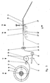
- FIG. 1 and 2 show a protective cover for holding framed slides or the like, which has two flexible sheet-like structures 1 and 2, which are band-shaped and are arranged essentially congruently one above the other.
- the flexible sheet-like structures preferably consist of transparent plastic film and are connected to one another in the area of one long side via a connection area 3 designed as a welded area.
- the two flat structures are connected to one another at their mutually facing flat sides at intervals by means of transverse connections 4, which in the exemplary embodiment shown are likewise designed as welded areas.
- pockets 5 are formed, which are used to hold framed slides 6.
- the long side opposite the closed long side 3 has insertion openings 7 through which the framed slides 6 can be inserted, if necessary after the insertion opening has been widened.
- connection area 3 on the closed long side has perforations 8, in which appropriately designed attack devices of a feed transport device (not shown here) can engage.
- the web-like cross-connection areas 4 are provided with openings 9, into which transport elements, for example transport pins, of a filling device can snap.
- the connecting areas 4 have such a width that a protective cover section can be cut in the longitudinal direction of the cross-connections and approximately in the middle thereof, without the lateral pocket limitation of the pockets 5 adjoining the right and left in each case being impaired.
- a closure device for the pocket openings 7 is designated by 10 in FIG. 1.
- the closure device can be implemented, for example, in that the flat structures 1 and 2 are spot-welded in the region of the pocket opening 7.
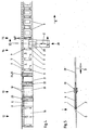
- the device shown in FIGS. 3 to 5 has a storage station designated by 12 for a protective cover 11, a buffer station 13 and a filling station 14 with cutting devices 15.
- a supply roll 16 of a protective cover 11 is arranged on a rolling device 17, 18, not shown in detail.
- the protective cover 11 has two flexible flat structures arranged essentially congruently one above the other with pockets for holding slides.
- the pockets are formed in that the protective cover has a connection area 3 on one long side and connection areas 4 arranged at intervals at a distance therefrom.
- the pockets 5 thus formed can be supplied with slides 6 through pocket openings 7.
- the connection area on the one long side has perforations 8 for attack devices 19 of a drum-like feed transport device 20 in the area of the buffer station 13.
- a loop 21 of the protective cover 11 is formed.
- a dancer roll 22 is attached between the device 20, which is designed, for example, as a toothed drum, and the single station 14, which is arranged such that it can be controlled or pivoted in the direction of the arrow B, for example via microswitches or a photo cell arrangement.
- Further roles of the buffer station are designated 23, 24 and 25, the protective cover 11 is fed to the filling station 14 from the supply station 12 via the buffer station 13 such that the transport system of the filling device 14 is relieved of the weight of the supply roll 16 and the train of the subsequent protective cover is.
- the cross connections 4 of the protective cover 11 have openings 9, which schematically represent one in FIG. 3 for the engagement of transport pins 26 provided filling transport device 27 are provided.
- the transport pins 26 can be moved with the filling transport device 27 in the feed direction C of the protective cover in the position shown in solid lines in FIG. 3, that is to say in a position in the region of the protective cover, in which the transport pins 26 thus engage in the openings 9 and in the transport direction C Pull the area of the protective cover lying behind the transport pins 26 and press the area in front of it.
- the area of the protective cover lying in front of the pins 26 which are latched into the openings 9 in the transport direction has, as can be seen from FIGS. 3 and 4, framed slides 6 already pocketed.
- the filler transport device 27 is lowered in such a way that the transport pins 26 disengage from the protective cover 11, and then the transport device 27 is moved in this position intermittently against the feed transport direction C until the one designated in FIG. 3 with 27 ' and position of the feed transport device shown in dashed lines is reached. From this position, the feed transport device 27 'is then raised again, so that the transport pins engage in the openings 9 in the subsequent cross connection 4, and then again a movement takes place in a raised position in the direction of arrow C, so that the next feed cycle can begin.
- the cutting device 15 can optionally be activated (via an arrangement not shown).
- the filling station 15 also has a filling device designated 28.
- the slide frames to be pocketed are fed to the filling device 28 via a device (not shown) and are pushed into the pockets 5 there by means of a slide 29 which can be cyclically moved back and forth in the direction of the arrow D transversely to the transport direction C.
- the slider 29 is assigned a widening device, shown schematically in FIG. 5 and designated by 30, by means of which the filling opening 7 of the pockets 5 between the flexible flat structures 1, 2 can be widened in such a way that a slide frame 6 to be inserted can be easily inserted.
- the operating cycle of the filling device 28 is coordinated with the operating cycle of the filling transport device in such a way that the filling by means of the slide 29 takes place against the feed direction C during the return transport movement of the filling transport device 27.
- the protective cover is both pulled and pushed by the feed transport device 29 in the area of the filling station in such a way that the protective cover area lying in front of the mounting area of the transport pins and already having a slide-in slide is pushed, so that neither empty strokes nor a separate transport device for the Area of the protective cover in front of and behind the filling station would be required.
- the filling station 15 can be followed or assigned a closing device (not shown), by means of which the filling openings 7 can be closed after slides 6 have been pocketed.
- connection area 3 between the flexible flat structures does not have to be formed continuously on the long side, but it can also be divided into individual connection areas.
Priority Applications (1)
| Application Number | Priority Date | Filing Date | Title |
|---|---|---|---|
| AT87109686T ATE53805T1 (de) | 1986-07-11 | 1987-07-04 | Schutzhuelle zur aufnahme von gerahmten diapositiven od. dgl. sowie eintaschvorrichtung hierzu. |
Applications Claiming Priority (2)
| Application Number | Priority Date | Filing Date | Title |
|---|---|---|---|
| DE3623383 | 1986-07-11 | ||
| DE19863623383 DE3623383A1 (de) | 1986-07-11 | 1986-07-11 | Schutzhuelle zur aufnahme von gerahmten diapositiven od. dgl. sowie eintaschvorrichtung hierzu |
Publications (3)
| Publication Number | Publication Date |
|---|---|
| EP0252467A2 EP0252467A2 (de) | 1988-01-13 |
| EP0252467A3 EP0252467A3 (en) | 1989-02-08 |
| EP0252467B1 true EP0252467B1 (de) | 1990-05-02 |
Family
ID=6304939
Family Applications (1)
| Application Number | Title | Priority Date | Filing Date |
|---|---|---|---|
| EP87109686A Expired - Lifetime EP0252467B1 (de) | 1986-07-11 | 1987-07-04 | Schutzhülle zur Aufnahme von gerahmten Diapositiven od. dgl. sowie Eintaschvorrichtung hierzu |
Country Status (5)
| Country | Link |
|---|---|
| EP (1) | EP0252467B1 (es) |
| AT (1) | ATE53805T1 (es) |
| DE (2) | DE3623383A1 (es) |
| ES (1) | ES2015926B3 (es) |
| GR (1) | GR3000812T3 (es) |
Families Citing this family (3)
| Publication number | Priority date | Publication date | Assignee | Title |
|---|---|---|---|---|
| DE4019531C2 (de) * | 1990-06-19 | 2000-10-19 | Johannes Loersch | Verfahren zum Eintaschen von nacheinander herangeführten Flächengebilden sowie Vorrichtung zur Durchführung des Verfahrens |
| DE29609429U1 (de) * | 1996-05-28 | 1996-08-14 | Loersch Johannes | Schutzhülle zur Aufnahme von Flächengebilden |
| US6952910B1 (en) | 2000-09-27 | 2005-10-11 | Loersch Johannes | Gas filled bodies |
Family Cites Families (2)
| Publication number | Priority date | Publication date | Assignee | Title |
|---|---|---|---|---|
| US3779449A (en) * | 1972-05-05 | 1973-12-18 | H Membrino | Linear strip of severable bags |
| DE3319202A1 (de) * | 1983-05-27 | 1984-11-29 | Société d'Application Plastique, Mécanique et Electronique Plastimécanique S.A., Falaise | Transportvorichtung fuer eine tiefziehmaschine zum verformen von folien oder platten aus thermoplastischem kunststoff |
-
1986
- 1986-07-11 DE DE19863623383 patent/DE3623383A1/de not_active Withdrawn
-
1987
- 1987-07-04 EP EP87109686A patent/EP0252467B1/de not_active Expired - Lifetime
- 1987-07-04 ES ES87109686T patent/ES2015926B3/es not_active Expired - Lifetime
- 1987-07-04 AT AT87109686T patent/ATE53805T1/de not_active IP Right Cessation
- 1987-07-04 DE DE8787109686T patent/DE3762501D1/de not_active Expired - Lifetime
-
1990
- 1990-07-13 GR GR90400465T patent/GR3000812T3/el unknown
Also Published As
| Publication number | Publication date |
|---|---|
| ES2015926B3 (es) | 1990-09-16 |
| GR3000812T3 (en) | 1991-11-15 |
| EP0252467A3 (en) | 1989-02-08 |
| EP0252467A2 (de) | 1988-01-13 |
| DE3623383A1 (de) | 1988-01-14 |
| DE3762501D1 (de) | 1990-06-07 |
| ATE53805T1 (de) | 1990-06-15 |
Similar Documents
| Publication | Publication Date | Title |
|---|---|---|
| EP0256346B1 (de) | Archivierbare Aufbewahrungstasche für Filmmaterial sowie Eintaschvorrichtung hierzu | |
| DE2723522A1 (de) | Anordnung zum ausrichten von belegen | |
| DE2539199A1 (de) | Verfahren und vorrichtung zum einrahmen von filmabschnitten in diapositiv-rahmen | |
| DE1611625A1 (de) | Einrichtung zur Orientierung von Behaelterzuschnitten | |
| DE2135675A1 (de) | Vorrichtung zum Anbringen und Fest klammern eines Beutels auf einer Forder apparatur | |
| DE2456840A1 (de) | Verfahren und vorrichtung zum transport nichtstabiler stapel von blattaehnlichem material | |
| EP0252467B1 (de) | Schutzhülle zur Aufnahme von gerahmten Diapositiven od. dgl. sowie Eintaschvorrichtung hierzu | |
| DE3008030C2 (de) | Vorrichtung zum Abschneiden von zwei entkuppelten fortlaufenden Reißverschlußbändern und zum Kuppeln der abgeschnittenen Reißverschlußbänder | |
| EP0272543B1 (de) | Einsteckvorrichtung, insbesondere für Falzprodukte | |
| DE2431319A1 (de) | Verpackungsmaschine zur schrumpffolienumkleidung von stueckgut | |
| DE2438555C3 (de) | Verpackung | |
| EP0478810A1 (de) | Verpackungseinheit | |
| CH681445A5 (en) | Device for spreading open flat bags | |
| DE2131611A1 (de) | Verfahren zum Zerschneiden entwickelter Filmstreifen in Filmabschnitte und zum unmittelbar anschliessenden Einfuehren derselben in Diapositivrahmen | |
| DE3507656C2 (es) | ||
| EP0401526A1 (de) | Clip-Verschluss für Beutel | |
| DE2349728B2 (de) | Vorrichtung zum Anbringen von Schiebern an Reißverschlußketten | |
| EP0109353A2 (de) | Verfahren zur Herstellung einer Verpackung aus einem flexiblen Einschlagmaterial | |
| DE3121353A1 (de) | Foerderanordnung fuer stabfoermige artikel der tabakverarbeitenden industrie | |
| EP0489279B1 (de) | Verfahren und Vorrichtung zum Entmanteln von in einstückigen Faltkartons verpackten tiefgefrorenen Blöcken in flacher Quaderform | |
| EP0915018A1 (de) | Verfahren zum Befüllen und Verschliessen von Säcken | |
| DE3500160A1 (de) | Vorrichtung zum stapeln und banderolieren von schildchen | |
| DE2826375C2 (de) | Vorrichtung zum Aufspreizen eines Folienbandes | |
| DE1012558B (de) | Vorrichtung zum Abschneiden und Aufkleben eines Aufreissstreifens | |
| DE4315288A1 (de) | Verfahren und Vorrichtung zum Einbringen von Diapositiv-Rähmchen oder dergleichen in eine Eintaschfolie |
Legal Events
| Date | Code | Title | Description |
|---|---|---|---|
| PUAI | Public reference made under article 153(3) epc to a published international application that has entered the european phase |
Free format text: ORIGINAL CODE: 0009012 |
|
| AK | Designated contracting states |
Kind code of ref document: A2 Designated state(s): AT BE CH DE ES FR GB GR IT LI NL SE |
|
| PUAL | Search report despatched |
Free format text: ORIGINAL CODE: 0009013 |
|
| RHK1 | Main classification (correction) |
Ipc: B65B 9/04 |
|
| AK | Designated contracting states |
Kind code of ref document: A3 Designated state(s): AT BE CH DE ES FR GB GR IT LI NL SE |
|
| 17P | Request for examination filed |
Effective date: 19890227 |
|
| 17Q | First examination report despatched |
Effective date: 19890825 |
|
| GRAA | (expected) grant |
Free format text: ORIGINAL CODE: 0009210 |
|
| AK | Designated contracting states |
Kind code of ref document: B1 Designated state(s): AT BE CH DE ES FR GB GR IT LI NL SE |
|
| REF | Corresponds to: |
Ref document number: 53805 Country of ref document: AT Date of ref document: 19900615 Kind code of ref document: T |
|
| REF | Corresponds to: |
Ref document number: 3762501 Country of ref document: DE Date of ref document: 19900607 |
|
| ITF | It: translation for a ep patent filed |
Owner name: LENZI & C. |
|
| ET | Fr: translation filed | ||
| GBT | Gb: translation of ep patent filed (gb section 77(6)(a)/1977) | ||
| REG | Reference to a national code |
Ref country code: GR Ref legal event code: FG4A Free format text: 3000812 |
|
| PLBE | No opposition filed within time limit |
Free format text: ORIGINAL CODE: 0009261 |
|
| STAA | Information on the status of an ep patent application or granted ep patent |
Free format text: STATUS: NO OPPOSITION FILED WITHIN TIME LIMIT |
|
| 26N | No opposition filed | ||
| ITTA | It: last paid annual fee | ||
| EAL | Se: european patent in force in sweden |
Ref document number: 87109686.3 |
|
| PGFP | Annual fee paid to national office [announced via postgrant information from national office to epo] |
Ref country code: GB Payment date: 19990621 Year of fee payment: 13 |
|
| PGFP | Annual fee paid to national office [announced via postgrant information from national office to epo] |
Ref country code: GR Payment date: 19990630 Year of fee payment: 13 |
|
| PGFP | Annual fee paid to national office [announced via postgrant information from national office to epo] |
Ref country code: SE Payment date: 19990719 Year of fee payment: 13 |
|
| PG25 | Lapsed in a contracting state [announced via postgrant information from national office to epo] |
Ref country code: GB Free format text: LAPSE BECAUSE OF NON-PAYMENT OF DUE FEES Effective date: 20000704 |
|
| PG25 | Lapsed in a contracting state [announced via postgrant information from national office to epo] |
Ref country code: SE Free format text: LAPSE BECAUSE OF NON-PAYMENT OF DUE FEES Effective date: 20000705 |
|
| PG25 | Lapsed in a contracting state [announced via postgrant information from national office to epo] |
Ref country code: GR Free format text: LAPSE BECAUSE OF NON-PAYMENT OF DUE FEES Effective date: 20000731 |
|
| GBPC | Gb: european patent ceased through non-payment of renewal fee |
Effective date: 20000704 |
|
| EUG | Se: european patent has lapsed |
Ref document number: 87109686.3 |
|
| PGFP | Annual fee paid to national office [announced via postgrant information from national office to epo] |
Ref country code: ES Payment date: 20010531 Year of fee payment: 15 |
|
| PGFP | Annual fee paid to national office [announced via postgrant information from national office to epo] |
Ref country code: FR Payment date: 20010727 Year of fee payment: 15 |
|
| PGFP | Annual fee paid to national office [announced via postgrant information from national office to epo] |
Ref country code: NL Payment date: 20010730 Year of fee payment: 15 Ref country code: BE Payment date: 20010730 Year of fee payment: 15 |
|
| PGFP | Annual fee paid to national office [announced via postgrant information from national office to epo] |
Ref country code: CH Payment date: 20010731 Year of fee payment: 15 Ref country code: AT Payment date: 20010731 Year of fee payment: 15 |
|
| PG25 | Lapsed in a contracting state [announced via postgrant information from national office to epo] |
Ref country code: AT Free format text: LAPSE BECAUSE OF NON-PAYMENT OF DUE FEES Effective date: 20020704 |
|
| PG25 | Lapsed in a contracting state [announced via postgrant information from national office to epo] |
Ref country code: ES Free format text: LAPSE BECAUSE OF NON-PAYMENT OF DUE FEES Effective date: 20020705 |
|
| PG25 | Lapsed in a contracting state [announced via postgrant information from national office to epo] |
Ref country code: LI Free format text: LAPSE BECAUSE OF NON-PAYMENT OF DUE FEES Effective date: 20020731 Ref country code: CH Free format text: LAPSE BECAUSE OF NON-PAYMENT OF DUE FEES Effective date: 20020731 Ref country code: BE Free format text: LAPSE BECAUSE OF NON-PAYMENT OF DUE FEES Effective date: 20020731 |
|
| BERE | Be: lapsed |
Owner name: *LORSCH JOHANNES Effective date: 20020731 |
|
| PG25 | Lapsed in a contracting state [announced via postgrant information from national office to epo] |
Ref country code: NL Free format text: LAPSE BECAUSE OF NON-PAYMENT OF DUE FEES Effective date: 20030201 |
|
| REG | Reference to a national code |
Ref country code: CH Ref legal event code: PL |
|
| PG25 | Lapsed in a contracting state [announced via postgrant information from national office to epo] |
Ref country code: FR Free format text: LAPSE BECAUSE OF NON-PAYMENT OF DUE FEES Effective date: 20030331 |
|
| NLV4 | Nl: lapsed or anulled due to non-payment of the annual fee |
Effective date: 20030201 |
|
| REG | Reference to a national code |
Ref country code: FR Ref legal event code: ST |
|
| REG | Reference to a national code |
Ref country code: ES Ref legal event code: FD2A Effective date: 20030811 |
|
| PGFP | Annual fee paid to national office [announced via postgrant information from national office to epo] |
Ref country code: DE Payment date: 20040614 Year of fee payment: 18 |
|
| PG25 | Lapsed in a contracting state [announced via postgrant information from national office to epo] |
Ref country code: IT Free format text: LAPSE BECAUSE OF NON-PAYMENT OF DUE FEES;WARNING: LAPSES OF ITALIAN PATENTS WITH EFFECTIVE DATE BEFORE 2007 MAY HAVE OCCURRED AT ANY TIME BEFORE 2007. THE CORRECT EFFECTIVE DATE MAY BE DIFFERENT FROM THE ONE RECORDED. Effective date: 20050704 |
|
| PG25 | Lapsed in a contracting state [announced via postgrant information from national office to epo] |
Ref country code: DE Free format text: LAPSE BECAUSE OF NON-PAYMENT OF DUE FEES Effective date: 20060201 |