EP0252467B1 - Protective cover for holding framed slides or similar, and associated jacketing device - Google Patents
Protective cover for holding framed slides or similar, and associated jacketing device Download PDFInfo
- Publication number
- EP0252467B1 EP0252467B1 EP87109686A EP87109686A EP0252467B1 EP 0252467 B1 EP0252467 B1 EP 0252467B1 EP 87109686 A EP87109686 A EP 87109686A EP 87109686 A EP87109686 A EP 87109686A EP 0252467 B1 EP0252467 B1 EP 0252467B1
- Authority
- EP
- European Patent Office
- Prior art keywords
- sheath
- transport
- filling
- pockets
- protective cover
- Prior art date
- Legal status (The legal status is an assumption and is not a legal conclusion. Google has not performed a legal analysis and makes no representation as to the accuracy of the status listed.)
- Expired - Lifetime
Links
Images

Classifications
-
- B—PERFORMING OPERATIONS; TRANSPORTING
- B65—CONVEYING; PACKING; STORING; HANDLING THIN OR FILAMENTARY MATERIAL
- B65D—CONTAINERS FOR STORAGE OR TRANSPORT OF ARTICLES OR MATERIALS, e.g. BAGS, BARRELS, BOTTLES, BOXES, CANS, CARTONS, CRATES, DRUMS, JARS, TANKS, HOPPERS, FORWARDING CONTAINERS; ACCESSORIES, CLOSURES, OR FITTINGS THEREFOR; PACKAGING ELEMENTS; PACKAGES
- B65D75/00—Packages comprising articles or materials partially or wholly enclosed in strips, sheets, blanks, tubes, or webs of flexible sheet material, e.g. in folded wrappers
- B65D75/28—Articles or materials wholly enclosed in composite wrappers, i.e. wrappers formed by associating or interconnecting two or more sheets or blanks
- B65D75/30—Articles or materials enclosed between two opposed sheets or blanks having their margins united, e.g. by pressure-sensitive adhesive, crimping, heat-sealing, or welding
-
- B—PERFORMING OPERATIONS; TRANSPORTING
- B65—CONVEYING; PACKING; STORING; HANDLING THIN OR FILAMENTARY MATERIAL
- B65B—MACHINES, APPARATUS OR DEVICES FOR, OR METHODS OF, PACKAGING ARTICLES OR MATERIALS; UNPACKING
- B65B43/00—Forming, feeding, opening or setting-up containers or receptacles in association with packaging
- B65B43/12—Feeding flexible bags or carton blanks in flat or collapsed state; Feeding flat bags connected to form a series or chain
- B65B43/123—Feeding flat bags connected to form a series or chain
-
- G—PHYSICS
- G03—PHOTOGRAPHY; CINEMATOGRAPHY; ANALOGOUS TECHNIQUES USING WAVES OTHER THAN OPTICAL WAVES; ELECTROGRAPHY; HOLOGRAPHY
- G03D—APPARATUS FOR PROCESSING EXPOSED PHOTOGRAPHIC MATERIALS; ACCESSORIES THEREFOR
- G03D15/00—Apparatus for treating processed material
- G03D15/10—Mounting, e.g. of processed material in a frame
Definitions
- the invention relates to a protective cover for holding framed slides or the like (according to the preamble of claim 1), and to a de-ashing device provided for this purpose, according to the preamble of claim 6, both known from OS-A 3 779 449.
- the invention is based on the object, on the one hand, of proposing a protective sleeve suitable for holding framed slides or the like and, moreover, of a device by means of which framed slides or the like can be pocketed in such a protective sleeve in the simplest possible manner.
- cross connections have openings suitable for enclosing transport elements.
- connection areas of the flat structures are designed as welded areas.
- attack devices for the feed transport devices are designed as perforations in connection areas in addition to the perforated ones on the closed long side.
- closure devices are provided for the pocket openings of the pockets, by means of which the pockets can be closed after the slides have been filled in so that the slides cannot accidentally fall out.
- the band-shaped flexible fabrics are preferably made of transparent plastic film.
- the invention offers the possibility of packaging framed slides or the like by filling them in the pockets in a simple manner so that dirt, scratches or the like do not occur.
- the protective cover can be supplied, for example, with a large number of pockets in a rolled-up form, and there is then not only the possibility of cutting off a piece from this supply with a number of pockets corresponding to the respective order, but it is also possible without further ado to further subdivide the protective cover assigned to an order by cutting off sections, for example in such a way that a section has three or four pockets, corresponding to a length such that these sections can easily be packed together with the paper images and sent, for example, by post.
- a cut can be made so that the cut is made approximately in the middle of the cross connections, in such a way that the pockets adjacent to both sides of the cut are not opened by the cut.
- cross connections forming the pockets do not necessarily have to be designed as welded areas, but other types of connection are also possible. It is also not necessary that the connection be linear.
- a device for pocketing framed slides or the like in a protective cover with pockets between two substantially congruent flexible surface structures and with pocket openings provided on one long side, in particular in a protective cover of the type described above, is characterized in that the protective cover is a Filling station can be fed from a supply station by means of a feed transport device via a buffer station, preferably having a loop of the protective cover, and the filling station is a filling device which works intermittently in the transverse direction to the transport direction of the protective cover, with a slide for inserting the slide and with an expanding device for expanding the respective pocket and with one has a filling transport device which operates in a clocked manner to the work cycle of the filling device, and the filling transport device has transport pins for latching n has openings in the transverse connections of the flexible flat structures dividing the individual pockets of the protective cover, and the transport pins of the protective cover can be moved in the feed direction into a position in the region of the protective cover and against the feed direction into a position outside the protective cover over
- the filling station has a Has cutting device for cutting off sections of the protective cover.
- the filling station is followed by a closing device for closing a filled bag.
- This closing device can be designed, for example, as a welding device that welds the pocket openings point by point.
- the buffer station arranged between the storage station and the filling station serves to relieve the transport system in the area of the filling station from the pull of the protective cover storage roll provided in the storage station, for example, so that the function of the filling transport device, which preferably has a gripper device, also functions at a high working speed and at the same time It is possible to deduct the protective cover from a protective cover supply roll.
- the transport pins which snap into the transverse connections between the individual pockets mean that the protective cover with an empty pocket is pushed into the area of the filling device and at the same time the protective cover area in front of it in the transport direction is covered with a slide filled bag is pushed or pushed out of the filling area. It is therefore possible to cut off the protective cover behind the filling station without empty strokes being necessary or without loss of protective cover material.
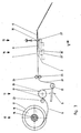
- FIG. 1 and 2 show a protective cover for holding framed slides or the like, which has two flexible sheet-like structures 1 and 2, which are band-shaped and are arranged essentially congruently one above the other.
- the flexible sheet-like structures preferably consist of transparent plastic film and are connected to one another in the area of one long side via a connection area 3 designed as a welded area.
- the two flat structures are connected to one another at their mutually facing flat sides at intervals by means of transverse connections 4, which in the exemplary embodiment shown are likewise designed as welded areas.
- pockets 5 are formed, which are used to hold framed slides 6.
- the long side opposite the closed long side 3 has insertion openings 7 through which the framed slides 6 can be inserted, if necessary after the insertion opening has been widened.
- connection area 3 on the closed long side has perforations 8, in which appropriately designed attack devices of a feed transport device (not shown here) can engage.
- the web-like cross-connection areas 4 are provided with openings 9, into which transport elements, for example transport pins, of a filling device can snap.
- the connecting areas 4 have such a width that a protective cover section can be cut in the longitudinal direction of the cross-connections and approximately in the middle thereof, without the lateral pocket limitation of the pockets 5 adjoining the right and left in each case being impaired.
- a closure device for the pocket openings 7 is designated by 10 in FIG. 1.
- the closure device can be implemented, for example, in that the flat structures 1 and 2 are spot-welded in the region of the pocket opening 7.
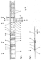
- the device shown in FIGS. 3 to 5 has a storage station designated by 12 for a protective cover 11, a buffer station 13 and a filling station 14 with cutting devices 15.
- a supply roll 16 of a protective cover 11 is arranged on a rolling device 17, 18, not shown in detail.
- the protective cover 11 has two flexible flat structures arranged essentially congruently one above the other with pockets for holding slides.
- the pockets are formed in that the protective cover has a connection area 3 on one long side and connection areas 4 arranged at intervals at a distance therefrom.
- the pockets 5 thus formed can be supplied with slides 6 through pocket openings 7.
- the connection area on the one long side has perforations 8 for attack devices 19 of a drum-like feed transport device 20 in the area of the buffer station 13.
- a loop 21 of the protective cover 11 is formed.
- a dancer roll 22 is attached between the device 20, which is designed, for example, as a toothed drum, and the single station 14, which is arranged such that it can be controlled or pivoted in the direction of the arrow B, for example via microswitches or a photo cell arrangement.
- Further roles of the buffer station are designated 23, 24 and 25, the protective cover 11 is fed to the filling station 14 from the supply station 12 via the buffer station 13 such that the transport system of the filling device 14 is relieved of the weight of the supply roll 16 and the train of the subsequent protective cover is.
- the cross connections 4 of the protective cover 11 have openings 9, which schematically represent one in FIG. 3 for the engagement of transport pins 26 provided filling transport device 27 are provided.
- the transport pins 26 can be moved with the filling transport device 27 in the feed direction C of the protective cover in the position shown in solid lines in FIG. 3, that is to say in a position in the region of the protective cover, in which the transport pins 26 thus engage in the openings 9 and in the transport direction C Pull the area of the protective cover lying behind the transport pins 26 and press the area in front of it.
- the area of the protective cover lying in front of the pins 26 which are latched into the openings 9 in the transport direction has, as can be seen from FIGS. 3 and 4, framed slides 6 already pocketed.
- the filler transport device 27 is lowered in such a way that the transport pins 26 disengage from the protective cover 11, and then the transport device 27 is moved in this position intermittently against the feed transport direction C until the one designated in FIG. 3 with 27 ' and position of the feed transport device shown in dashed lines is reached. From this position, the feed transport device 27 'is then raised again, so that the transport pins engage in the openings 9 in the subsequent cross connection 4, and then again a movement takes place in a raised position in the direction of arrow C, so that the next feed cycle can begin.
- the cutting device 15 can optionally be activated (via an arrangement not shown).
- the filling station 15 also has a filling device designated 28.
- the slide frames to be pocketed are fed to the filling device 28 via a device (not shown) and are pushed into the pockets 5 there by means of a slide 29 which can be cyclically moved back and forth in the direction of the arrow D transversely to the transport direction C.
- the slider 29 is assigned a widening device, shown schematically in FIG. 5 and designated by 30, by means of which the filling opening 7 of the pockets 5 between the flexible flat structures 1, 2 can be widened in such a way that a slide frame 6 to be inserted can be easily inserted.
- the operating cycle of the filling device 28 is coordinated with the operating cycle of the filling transport device in such a way that the filling by means of the slide 29 takes place against the feed direction C during the return transport movement of the filling transport device 27.
- the protective cover is both pulled and pushed by the feed transport device 29 in the area of the filling station in such a way that the protective cover area lying in front of the mounting area of the transport pins and already having a slide-in slide is pushed, so that neither empty strokes nor a separate transport device for the Area of the protective cover in front of and behind the filling station would be required.
- the filling station 15 can be followed or assigned a closing device (not shown), by means of which the filling openings 7 can be closed after slides 6 have been pocketed.
- connection area 3 between the flexible flat structures does not have to be formed continuously on the long side, but it can also be divided into individual connection areas.
Landscapes
- Engineering & Computer Science (AREA)
- Mechanical Engineering (AREA)
- General Physics & Mathematics (AREA)
- Chemical & Material Sciences (AREA)
- Composite Materials (AREA)
- Physics & Mathematics (AREA)
- Containers And Plastic Fillers For Packaging (AREA)
- Telephone Set Structure (AREA)
- Dental Tools And Instruments Or Auxiliary Dental Instruments (AREA)
- Sampling And Sample Adjustment (AREA)
- Details Of Indoor Wiring (AREA)
- Packaging Of Annular Or Rod-Shaped Articles, Wearing Apparel, Cassettes, Or The Like (AREA)
- Respiratory Apparatuses And Protective Means (AREA)
- Sheet Holders (AREA)
- Details Of Garments (AREA)
Abstract
Description
Die Erfindung betrifft eine Schutzhülle zur Aufnahme von gerahmten Diapositiven od. dgl. (gem. Oberbegriff des Anspruchs 1), sowie eine hierzu vorgesehene Entaschvorrichtung, gemäß Oberbegriff des Anspruch 6, beides bekannt aus OS-A 3 779 449.The invention relates to a protective cover for holding framed slides or the like (according to the preamble of claim 1), and to a de-ashing device provided for this purpose, according to the preamble of
Bei manchen Bearbeitungsvorgängen von Diapositiven od. dgl. ist es erforderlich, eine jeweils zugeordnete Menge (beispielseise Größenordnung 30 Stück, entsprechend der Menge von auf einem Kleinbildfilm enthaltenen Bildern) zu verpacken. Diese Aufgabe besteht beispielsweise dann, wenn mittels einer hierzu geeigneten Vorrichtung von gerahmten Diapositiven Negativ-Papierbilder hergestellt werden sollen. Neuere derartige Vorrichtungen sind beispielsweise derart ausgebildet, daß eine Anzahl von in einem sog. Diamagazin enthaltenen Diapositiven in die Vorrichtung eingesetzt werden kann. In der Vorrichtung werden von den einzelnen Diapositiven dann Negativ-Papierbilder angefertigt. Die Papierbilder werden geschnitten, und letztlich ist es erforderlich, die Negativ-Papierbilder und die Diapositive einander zuzuordnen. Bei einer bekannten Vorrichtung ist hierzu vorgesehen, daß die Diapositive auf ein Transportband fallen, auf welchem sie schuppenartig übereinanderliegen. Von hier werden sie von einer Bedienungsperson von Hand aufgenommen und mit den Papierbildern in eine Versandtasche od. dgl. gepackt. Da den einzelnen zu bearbeitenden Aufträgen meist relativ viele Diapositive (entsprechend der auf einem Film enthaltenen Bildanzahl) zugeordnet sind, besteht das Problem daß die schuppenartige Anordnung der Diapositive auf dem Transportband nicht griffgerecht ist, so daß das Erfassen von Hand Schwierigkeiten bereitet. Weiterhin ist von Nachteil, daß die Diapositive ungeschützt in die Versandtasche od. dgl. eingepackt werden, was zu Verschmutzungen, Verkratzungen od. dgl. führen kann.In some processing operations for slides or the like, it is necessary to pack an assigned quantity (for example, around 30 pieces, corresponding to the quantity of images contained on a 35 mm film). This task exists, for example, when negative paper images are to be produced by means of a suitable device for framed slides. Newer devices of this type are designed, for example, in such a way that a number of slides contained in a so-called slide magazine can be inserted into the device. The individual slides are then used to produce negative paper images in the device. The paper images are cut, and ultimately it is necessary to match the negative paper images and the transparencies. In a known device, it is provided that the slides fall onto a conveyor belt on which they lie one above the other like scales. From here, they are picked up by an operator by hand and packed with the paper pictures in a mailing bag or the like. Since the individual orders to be processed are usually assigned a relatively large number of slides (corresponding to the number of images contained on a film), there is the problem that the scale-like arrangement of the slides on the conveyor belt is not within easy reach, so that manual recording is difficult. Another disadvantage is that the slides are packed unprotected in the mailing bag or the like, which can lead to soiling, scratching or the like.
Der Erfindung liegt die Aufgabe zugrunde, zum einen eine zur Aufnahme von gerahmten Diapositiven od. dgl. geeignete Schutzhülle und darüber hinaus eine Vorrichtung vorzuschlagen, mittels derer gerahmte Diapositive od. dgl. in eine derartige Schutzhülle in möglichst einfacher Weise eingetascht werden können.The invention is based on the object, on the one hand, of proposing a protective sleeve suitable for holding framed slides or the like and, moreover, of a device by means of which framed slides or the like can be pocketed in such a protective sleeve in the simplest possible manner.
Die der Erfindung zugrundeliegende Aufgabe wird dadurch gelöst, daß Querverbindungen zum Einfassen von Transportelementen geeignete Öffnungen aufweisen.The object on which the invention is based is achieved in that cross connections have openings suitable for enclosing transport elements.
In bevorzugter Ausgestaltung der Erfindung ist vorgesehen, daß die Verbindungsbereiche der Flächengebilde als verschweißte Bereiche ausgebildet sind.In a preferred embodiment of the invention it is provided that the connection areas of the flat structures are designed as welded areas.
Die Angriffseinrichtungen für die Vorschubtransporteinrichtungen sind in weiterer Ausgestaltung der Erfindung als Perforationen in Verbindungsbereichen zusätzlich zu den perforierten an der geschlossenen Längsseite ausgebildet.In a further embodiment of the invention, the attack devices for the feed transport devices are designed as perforations in connection areas in addition to the perforated ones on the closed long side.
Weiterhin kann erfindungsgmäß vorgesehen sein, daß Verschlußeinrichtungen für die Eintaschöffnungen der Taschen vorgesehen sind, mittels derer die Taschen nach dem Einfüllen der Diapositive so verschlossen werden können, daß ein unbeabsichtigtes Herausfallen der Diapositive nicht möglich ist.Furthermore, it can be provided according to the invention that closure devices are provided for the pocket openings of the pockets, by means of which the pockets can be closed after the slides have been filled in so that the slides cannot accidentally fall out.
Die bandförmigen flexiblen Flächengebilde bestehen vorzugsweise aus durchsichtiger Kunststoff-Folie.The band-shaped flexible fabrics are preferably made of transparent plastic film.
Die Erfindung bietet die Möglichkeit, gerahmte Diapositive od. dgl. durch Einfüllen in die Taschen in einfacher Weise so zu verpacken, daß Verschmutzungen, Verkratzungen od. dgl. nicht auftreten. Die Schutzhülle kann beispielsweise mit einer großen Anzahl von Taschen in aufgerollter Form geliefert werden, und es besteht dann nicht nur die Möglichkeit, von diesem Vorrat ein Stück mit einer dem jeweiligen Auftrag entsprechenden Anzahl von Taschen abzuschneiden, sondern es ist auch ohne weiteres möglich, die einem Auftrag zugeordnete Schutzhülle durch Abschneiden von Abschnitten weiter zu unterteilen, beispielsweise so, daß ein Abschnitt drei oder vier Taschen aufweist, entsprechend einer solchen Länge, daß diese Abschnitte problemlos gemeinsam mit den Papierbildern eingepackt und beispielsweise per Post versandt werden können. Ein Abschneiden kann so erfolgen, daß der Schnitt etwa in der Mitte der Querverbindungen erfolgt, derart, daß die beidseitig des Schnittes angrenzenden Taschen durch den Schnitt nicht geöffnet werden.The invention offers the possibility of packaging framed slides or the like by filling them in the pockets in a simple manner so that dirt, scratches or the like do not occur. The protective cover can be supplied, for example, with a large number of pockets in a rolled-up form, and there is then not only the possibility of cutting off a piece from this supply with a number of pockets corresponding to the respective order, but it is also possible without further ado to further subdivide the protective cover assigned to an order by cutting off sections, for example in such a way that a section has three or four pockets, corresponding to a length such that these sections can easily be packed together with the paper images and sent, for example, by post. A cut can be made so that the cut is made approximately in the middle of the cross connections, in such a way that the pockets adjacent to both sides of the cut are not opened by the cut.
Die die Taschen bildenden Querverbindungen müssen nicht unbedingt als verschweißte Bereiche ausgebildet sein, sondern es sind auch andere Verbindungsarten möglich. Es ist auch nicht erforderlich, daß die Verbindung linienförmig ausgebildet sein muß.The cross connections forming the pockets do not necessarily have to be designed as welded areas, but other types of connection are also possible. It is also not necessary that the connection be linear.
Eine Vorrichtung zum Eintaschen von gerahmten Diapositiven od. dgl. in eine Schutzhülle mit Taschen zwischen zwei im wesentlichen deckungsgleich übereinander angeordneten flexiblen Flächengebilden und mit an einer Längsseite vorgesehenen Eintaschöffnungen, insbesondere in eine Schutzhülle der vorstehend beschriebenen Art, ist dadurch gekennzeichnet, daß die Schutzhülle einer Einfüllstation aus einer Vorratsstation mittels einer Vorschubtansporteinrichtung über eine vorzugsweise eine Schlaufe der Schutzhülle aufweisende Pufferstation zuführbar ist, und die Einfüllstation eine in Querrichtung zur Transportrichtung der Schutzhülle taktweise arbeitende Einfülleinrichtung mit einem Schieber zum Einschieben des Diapositivs und mit einer Aufweiteinrichtung zum Aufweiten der jeweiligen Tasche und mit einer versetzt zum Arbeitstakt der Einfülleinrichtung taktweise arbeitenden Einfülltransporteinrichtung aufweist, und die Einfülltransporteinrichtung Transportstifte zum Einrasten in Öffnungen der die einzelnen Taschen der Schutzhülle unterteilenden Querverbindungen der flexiblen Flächengebilde aufweist, und die Transportstifte der Schutzhülle über einen wenigstens eine Taschenbreite einschließenden Bereich der Schutzhülle in Vorschubrichtung in eine Lage im Bereich der Schutzhülle und entgegen der Vorschubrichtung in eine Lage außerhalb der Schutzhülle bewegbar angeordnet sind.A device for pocketing framed slides or the like in a protective cover with pockets between two substantially congruent flexible surface structures and with pocket openings provided on one long side, in particular in a protective cover of the type described above, is characterized in that the protective cover is a Filling station can be fed from a supply station by means of a feed transport device via a buffer station, preferably having a loop of the protective cover, and the filling station is a filling device which works intermittently in the transverse direction to the transport direction of the protective cover, with a slide for inserting the slide and with an expanding device for expanding the respective pocket and with one has a filling transport device which operates in a clocked manner to the work cycle of the filling device, and the filling transport device has transport pins for latching n has openings in the transverse connections of the flexible flat structures dividing the individual pockets of the protective cover, and the transport pins of the protective cover can be moved in the feed direction into a position in the region of the protective cover and against the feed direction into a position outside the protective cover over an area of at least one pocket width are arranged.
In zweckmäßiger Ausgestaltung kann weiterhin vorgesehen sein, daß die Einfüllstation eine Schneideinrichtung zum Abschneiden von Abschnitten der Schutzhülle aufweist.In an expedient embodiment, it can further be provided that the filling station has a Has cutting device for cutting off sections of the protective cover.
Weiterhin kann vorgesehen sein, daß der Einfüllstation eine Verschließeinrichtung zum Verschließen einer jeweils gefüllten Tasche nachgeschaltet ist. Diese Verschließeinrichtung kann beispielsweise als Verschweißeinrichtung ausgebildet sein, die die Taschenöffnungen punktweise verschweißt.Furthermore, it can be provided that the filling station is followed by a closing device for closing a filled bag. This closing device can be designed, for example, as a welding device that welds the pocket openings point by point.
Die zwischen der Vorratsstation und der Einfüllstation angeordnete Pufferstation dient, dazu, das Transportsystem im Bereich der Einfüllstation von dem Zug der in der Vorratsstation beispielsweise vorgesehenen Schutzhüllen-Vorratsrolle zu entlasten, so daß die Funktion der vorzugsweise eine Greifereinrichtung aufweisenden Einfülltransporteinrichtung auch bei hohem Arbeitstempo und gleichzeitigem Abzug der Schutzhülle von einer Schutzhüllen-Vorratsrolle möglich ist.The buffer station arranged between the storage station and the filling station serves to relieve the transport system in the area of the filling station from the pull of the protective cover storage roll provided in the storage station, for example, so that the function of the filling transport device, which preferably has a gripper device, also functions at a high working speed and at the same time It is possible to deduct the protective cover from a protective cover supply roll.
Bei der erfindungsgemäßen Vorrichtung ist besonders vorteilhaft, daß durch die in die Querverbindungen zwischen den einzelnen Taschen einrastenden Transportstifte erreicht wird, daß dadurch die Schutzhülle mit einer leeren Tasche in den Bereich der Einfülleinrichtung geschoben und gleichzeitig der in Transportrichtung davor befindliche Schutzhüllenbereich mit einer mit einem Diapositiv gefüllten Tasche aus dem Einfüllbereich gedrückt bzw. geschoben wird. Ein Abschneiden der Schutzhülle hinter der Einfüllstation ist somit möglich, ohne daß Leerhübe erforderlich sind oder ein Verlust an Schutzhüllenmaterial auftritt.In the device according to the invention it is particularly advantageous that the transport pins which snap into the transverse connections between the individual pockets mean that the protective cover with an empty pocket is pushed into the area of the filling device and at the same time the protective cover area in front of it in the transport direction is covered with a slide filled bag is pushed or pushed out of the filling area. It is therefore possible to cut off the protective cover behind the filling station without empty strokes being necessary or without loss of protective cover material.
Die Erfindung wird nachfolgend anhand des in den Zeichnungen dargestellten Ausführungsbeispiels näher erläutert. Es zeigen:
- Fig. 1 eine Draufsicht auf einen Abschnitt der Schutzhülle mit einem in eine Tasche eingetaschten Diapositiv;
- Fig. 2 eine Teilansicht von Fig. 1 in Pfeilrichtung A gesehen;
- Fig. 3 eine schematische Seitenansicht einer Vorrichtung zum Eintaschen von gerahmten Diapositiven in eine Schutzhülle gemäß Fig. 1;
- Fig. 4 eine schematische Draufsicht auf die Vorrichtung gemäß Fig. 3;
- Fig. 5 eine schematische Schnittdarstellung etwa längs der Linie V-V in Fig. 4.
- Figure 1 is a plan view of a portion of the protective cover with a slide pocketed in a pocket.
- Fig. 2 is a partial view of Figure 1 seen in the direction of arrow A;
- 3 shows a schematic side view of a device for pocketing framed slides into a protective cover according to FIG. 1;
- FIG. 4 shows a schematic top view of the device according to FIG. 3;
- 5 shows a schematic sectional illustration approximately along the line VV in FIG. 4.
In Fig. 1 und Fig. 2 ist eine Schutzhülle zur Aufnahme von gerahmten Diapositiven od. dgl. dargestellt, die zwei flexible Flächengebilde 1 und 2 aufweist, welche bandförmig ausgebildet und im wesentlichen deckungsgleich übereinander angeordnet sind. Die flexiblen Flächengebilde bestehen vorzugsweise aus durchsichtiger Kunststoff-Folie und sind im Bereich einer Längsseite über einen als verschweißten Bereich ausgebildeten Verbindungsbereich 3 miteinander verbunden. Außerdem sind die beiden Flächengebilde an ihren einander zugewandten Flachseiten in Abständen über Querverbindungen 4 miteinander verbunden, welche bei dem gezeigten Ausführungsbeispiel ebenfalls als verschweißte Bereiche ausgebildet sind. Dadurch sind Taschen 5 gebildet, welche zur Aufnahme von gerahmten Diapositiven 6 dienen. Die der geschlossenen Längsseite 3 gegenüberliegende Längsseite weist Eintaschöffnungen 7 auf, durch welche die gerahmten Diapositive 6 - ggf. nach Aufweiten der Eintaschöffnung - eingeschoben werden können.1 and 2 show a protective cover for holding framed slides or the like, which has two flexible sheet-
Der Verbindungsbereich 3 an der geschlossenen Längsseite weist Perforationen 8 auf, in welche entsprechend ausgebildete Angriffseinrichtungen einer Vorschubtransporteinrichtung (hier nicht dargestellt) eingreifen können. Die stegartig ausgebildeten Querverbindungsbereiche 4 sind mit Öffnungen 9 versehen, in welche Transportelemente, beispielsweise Transportstifte, einer Einfülleinrichtung einrasten können. Die Verbindungsbereiche 4 weisen eine solche Breite auf, daß ein Abschneiden eines Schutzhüllenabschnittes in Längsrichtung der Querverbindungen und etwa in deren Mitte möglich ist, ohne daß die seitliche Taschenbegrenzung der jeweils rechts und links angrenzenden Taschen 5 beeinträchtigt würde.The
Eine Verschlußeinrichtung für die Eintaschöffnungen 7 ist in Fig. 1 mit 10 bezeichnet. Die Verschlußeinrichtung kann beispielsweise dadurch realisiert werden, daß die Flächengebilde 1 und 2 im Bereich der Eintaschöffnung 7 punktverschweißt sind.A closure device for the
Die Schutzhülle gemäß Fig. 1 ist insgesamt mit 11 bezeichnet.1 is designated 11 overall.
Die in Fig. 3 bis Fig. 5 dargestellte Vorrichtung weist eine mit 12 bezeichnete Vorratsstation für eine Schutzhülle 11, eine Pufferstation 13 und eine Einfüllstation 14 mit Schneideinrichtungen 15 auf.The device shown in FIGS. 3 to 5 has a storage station designated by 12 for a
In der Vorratsstation 12 ist eine Vorratsrolle 16 einer Schutzhülle 11 auf einer nicht im einzelnen dargestellten Abrollvorrichtung 17, 18 angeordnet. Die Schutzhülle 11 weist zwei im wesentlichen deckungsgleich übereinander angeordnete flexible Flächengebilde mit Taschen zur Aufnahme von Diapositiven auf. Die Taschen sind dadurch gebildet, daB die Schutzhülle an einer Längsseite einen Verbindungsbereich 3 sowie in Abständen quer dazu angeordnete Verbindungsbereiche 4 aufweist. Den so gebildeten Taschen 5 sind Diapositive 6 durch Eintaschöffnungen 7 zuführbar. Der Verbindungsbereich an der einen Längsseite weist Perforationen 8 für Angriffseinrichtungen 19 einer trommelartig ausgebildeten Vorschubtransporteinrichtung 20 im Bereich der Pufferstation 13 auf. In der schematisch dargestellen Pufferstation 13 wird im übrigen eine Schlaufe 21 der Schutzhülle 11 gebildet. In Transportrichtung zwischen der Vorratsstation 12 und der Einfüllstation 14 ist zwischen der beispielsweise als Zahntrommel ausgebildeten Einrichtung 20 und der Einzelstation 14 eine Tänzerrolle 22 angebracht, welche beispielsweise über Mikroschalter oder eine Fotozellenanordnung in Pfeilrichtung B steuerbar bzw. verschwenkbar angeordnet ist. Weitere Rollen der Pufferstation sind mit 23, 24 und 25 bezeichnet, Die Schutzhülle 11 wird der Einfüllstation 14 von der Vorratsstation 12 über die Pufferstation 13 derart zugeführt, daß das Transportsystem der Einfülleinrichtung 14 von dem Gewicht der Vorratsrolle 16 und dem Zug der nachfolgenden Schutzhülle entlastet ist.In the
Die Querverbindungen 4 der Schutzhülle 11 weisen Öffnungen 9 auf, welche zum Einrasten von Transportstiften 26 einer in Fig. 3 schematisch dargestellten Einfülltransporteinrichtung 27 vorgesehen sind. Die Transportstifte 26 sind mit der Einfülltransporteinrichtung 27 in Vorschubrichtung C der Schutzhülle in der in Fig. 3 in ausgezogenen Linien dargestellten Lage bewegbar, also in einer Lage im Bereich der Schutzhülle, in der also die Transportstifte 26 in die Öffnungen 9 einfassen und den in Transportrichtung C hinter den Transportstiften 26 liegenden Bereich der Schutzhülle ziehen und den davorliegenden Bereich drücken. Der in Transportrichtung vor dem in die Öffnungen 9 eingerasteten Stifte 26 liegende Bereich der Schutzhülle weist, wie aus Fig. 3 und Fig. 4 ersichtlich, bereits eingetaschte gerahmte Diapositive 6 auf. Nach Erreichen der Schneideinrichtung 15 wird die Einfülltransporteinrichtung 27 derart abgesenkt, daß die Transportstifte 26 außer Eingriff mit der Schutzhülle 11 gelangen, und dann wird die Transporteinrichtung 27 taktweise in dieser Lage entgegen der Vorschubtransportrichtung C bewegt, bis die in Fig. 3 mit 27' bezeichnete und gestrichelt dargestellte Lage der Vorschubtransporteinrichtung erreicht ist. Von dieser Position aus wird die Vorschubtransporteinrichtung 27' dann wieder angehoben, so daß die Transportstifte in die Öffnungen 9 in der nachfolgenden Querverbindung 4 einfassen, und anschließend erfolgt wiederum eine Bewegung in angehobener Lage in Pfeilrichtung C, so daß der nächste Vorschubtakt beginnen kann. Die Schneideinrichtung 15 kann (über eine nicht dargestellte Anordnung) wahlweise aktiviert werden.The
Die Einfüllstation 15 weist außerdem eine mit 28 bezeichnete Einfülleinrichtung auf. Der Einfülleinrichtung 28 werden die einzutaschenden Diarahmen über eine (nicht dargestellte) Vorrichtung zugeführt und dort mittels eines Schiebers 29, der quer zur Transportrichtung C taktweise in Pfeilrichtung D hin- und herbewegbar angeordnet ist, in die Taschen 5 hineingeschoben. Dem Schieber 29 ist eine in Fig. 5 schematisch dargestellte und mit 30 bezeichnete Aufweiteinrichtung zugeordnet, mittels derer die Einfüllöffnung 7 der Taschen 5 zwischen den flexiblen Flächengebilden 1, 2 so aufgeweitet werden kann, daß ein einzutaschender Diarahmen 6 ohne weiteres eingeschoben werden kann.The filling
Der Arbeitstakt der Einfülleinrichtung 28 ist mit dem Arbeitstakt der Einfülltransporteinrichtung derart abgestimmt, daß das Einfüllen mittels des Schiebers 29 jeweils während der Rücktransportbewegung der Einfülltransporteinrichtung 27 entgegen der Vorschubrichtung C erfolgt.The operating cycle of the filling
Wie ersichtlich, wird die Schutzhülle durch die Vorschubtransporteinrichtung 29 im Bereich der Einfüllstation sowohl gezogen als auch geschoben, derart, daß die vor dem Einfaßbereich der Transportstifte liegende und ein bereits eingetaschtes Diapositiv aufweisende Schutzhüllenbereich geschoben wird, so daß weder Leerhübe noch eine gesonderte Transporteinrichtung für den Bereich der Schutzhülle vor und hinter der Einfüllstation erforderlich wären.As can be seen, the protective cover is both pulled and pushed by the
Der Einfüllstation 15 kann eine Verschließeinrichtung (nicht dargestellt) nachgeschaltet oder zugeordnet sein, mittels derer die Einfüllöffnungen 7 nach dem Eintaschen von Diapositiven 6 verschlossen werden kann.The filling
Der Verbindungsbereich 3 zwischen den flexiblen Flächengebilden muß nicht durchgehend an der Längsseite ausgebildet sein, sondern er kann auch in einzelne Verbindungsbereiche unterteilt sein.The
Claims (9)
Priority Applications (1)
| Application Number | Priority Date | Filing Date | Title |
|---|---|---|---|
| AT87109686T ATE53805T1 (en) | 1986-07-11 | 1987-07-04 | PROTECTIVE COVER FOR FRAMED SLIDES OD. DGL. AS WELL AS POCKET DEVICE THEREOF. |
Applications Claiming Priority (2)
| Application Number | Priority Date | Filing Date | Title |
|---|---|---|---|
| DE19863623383 DE3623383A1 (en) | 1986-07-11 | 1986-07-11 | PROTECTIVE COVER FOR RECEIVING FRAMED DIAPOSITIVE OD. DGL. AND A POCKET DEVICE THEREFOR |
| DE3623383 | 1986-07-11 |
Publications (3)
| Publication Number | Publication Date |
|---|---|
| EP0252467A2 EP0252467A2 (en) | 1988-01-13 |
| EP0252467A3 EP0252467A3 (en) | 1989-02-08 |
| EP0252467B1 true EP0252467B1 (en) | 1990-05-02 |
Family
ID=6304939
Family Applications (1)
| Application Number | Title | Priority Date | Filing Date |
|---|---|---|---|
| EP87109686A Expired - Lifetime EP0252467B1 (en) | 1986-07-11 | 1987-07-04 | Protective cover for holding framed slides or similar, and associated jacketing device |
Country Status (5)
| Country | Link |
|---|---|
| EP (1) | EP0252467B1 (en) |
| AT (1) | ATE53805T1 (en) |
| DE (2) | DE3623383A1 (en) |
| ES (1) | ES2015926B3 (en) |
| GR (1) | GR3000812T3 (en) |
Families Citing this family (3)
| Publication number | Priority date | Publication date | Assignee | Title |
|---|---|---|---|---|
| DE4019531C2 (en) * | 1990-06-19 | 2000-10-19 | Johannes Loersch | Method for pocketing sheets brought up one after the other and device for carrying out the method |
| DE29609429U1 (en) * | 1996-05-28 | 1996-08-14 | Loersch Johannes | Protective cover for holding flat structures |
| DE50015744D1 (en) | 2000-09-27 | 2009-10-29 | Johannes Loersch | Plastic hose for the production of gas-filled packing and device for filling |
Family Cites Families (2)
| Publication number | Priority date | Publication date | Assignee | Title |
|---|---|---|---|---|
| US3779449A (en) * | 1972-05-05 | 1973-12-18 | H Membrino | Linear strip of severable bags |
| DE3319202A1 (en) * | 1983-05-27 | 1984-11-29 | Société d'Application Plastique, Mécanique et Electronique Plastimécanique S.A., Falaise | Transport device for a thermoforming machine for forming films or sheets from thermoplastic |
-
1986
- 1986-07-11 DE DE19863623383 patent/DE3623383A1/en not_active Withdrawn
-
1987
- 1987-07-04 AT AT87109686T patent/ATE53805T1/en not_active IP Right Cessation
- 1987-07-04 ES ES87109686T patent/ES2015926B3/en not_active Expired - Lifetime
- 1987-07-04 DE DE8787109686T patent/DE3762501D1/en not_active Expired - Lifetime
- 1987-07-04 EP EP87109686A patent/EP0252467B1/en not_active Expired - Lifetime
-
1990
- 1990-07-13 GR GR90400465T patent/GR3000812T3/en unknown
Also Published As
| Publication number | Publication date |
|---|---|
| EP0252467A3 (en) | 1989-02-08 |
| DE3762501D1 (en) | 1990-06-07 |
| ES2015926B3 (en) | 1990-09-16 |
| ATE53805T1 (en) | 1990-06-15 |
| EP0252467A2 (en) | 1988-01-13 |
| GR3000812T3 (en) | 1991-11-15 |
| DE3623383A1 (en) | 1988-01-14 |
Similar Documents
| Publication | Publication Date | Title |
|---|---|---|
| EP0256346B1 (en) | Film bag for film material and device for introducing the material into it | |
| DE3413947C2 (en) | ||
| DE2723522A1 (en) | ARRANGEMENT FOR ALIGNING DOCUMENTS | |
| DE2539199A1 (en) | METHOD AND DEVICE FOR FRAMING FILM SECTIONS IN DIAPOSITIVE FRAMES | |
| DE1611625A1 (en) | Device for the orientation of container blanks | |
| DE2135675A1 (en) | Device for attaching and firmly stapling a bag on a front apparatus | |
| DE2456840A1 (en) | METHOD AND DEVICE FOR TRANSPORTING NONSTABLE STACKS OF MATERIAL LIKE SHEET | |
| EP0252467B1 (en) | Protective cover for holding framed slides or similar, and associated jacketing device | |
| DE3008030C2 (en) | Device for cutting off two uncoupled continuous zip fastener tapes and for coupling the cut zip fastener tapes | |
| DE3644423A1 (en) | PLUG-IN DEVICE, ESPECIALLY FOR FOLDED PRODUCTS | |
| DE2431319A1 (en) | PACKAGING MACHINE FOR SHRINK FILM COVERING OF PIECE GOODS | |
| DE2438555C3 (en) | packaging | |
| EP0478810A1 (en) | Packaging unit | |
| EP0401526A1 (en) | Clip closure for bag | |
| DE2133859A1 (en) | Film package for use in a daylight handling system | |
| CH681445A5 (en) | Device for spreading open flat bags | |
| DE2131611A1 (en) | Process for cutting developed film strips into film sections and for immediately inserting them into slide frames | |
| EP0915018B1 (en) | Method of filling and closing bags | |
| DE2349728B2 (en) | Device for attaching sliders to zip fastener chains | |
| EP0109353A2 (en) | Method of manufacturing a Package from flexible material | |
| DE3121353A1 (en) | Conveying arrangement for rod-shaped articles of the tobacco-processing industry | |
| EP0489279B1 (en) | Method and device for unwrapping flat rectangular deep-frozen blocks packaged in one-piece foldable cartons | |
| DE3010180C2 (en) | Device for spreading a foil strip | |
| DE3500160A1 (en) | DEVICE FOR STACKING AND BANDEROLING TAGS | |
| DE1971954U (en) | DEVICE FOR PACKAGING SHEETS. |
Legal Events
| Date | Code | Title | Description |
|---|---|---|---|
| PUAI | Public reference made under article 153(3) epc to a published international application that has entered the european phase |
Free format text: ORIGINAL CODE: 0009012 |
|
| AK | Designated contracting states |
Kind code of ref document: A2 Designated state(s): AT BE CH DE ES FR GB GR IT LI NL SE |
|
| PUAL | Search report despatched |
Free format text: ORIGINAL CODE: 0009013 |
|
| RHK1 | Main classification (correction) |
Ipc: B65B 9/04 |
|
| AK | Designated contracting states |
Kind code of ref document: A3 Designated state(s): AT BE CH DE ES FR GB GR IT LI NL SE |
|
| 17P | Request for examination filed |
Effective date: 19890227 |
|
| 17Q | First examination report despatched |
Effective date: 19890825 |
|
| GRAA | (expected) grant |
Free format text: ORIGINAL CODE: 0009210 |
|
| AK | Designated contracting states |
Kind code of ref document: B1 Designated state(s): AT BE CH DE ES FR GB GR IT LI NL SE |
|
| REF | Corresponds to: |
Ref document number: 53805 Country of ref document: AT Date of ref document: 19900615 Kind code of ref document: T |
|
| REF | Corresponds to: |
Ref document number: 3762501 Country of ref document: DE Date of ref document: 19900607 |
|
| ITF | It: translation for a ep patent filed |
Owner name: LENZI & C. |
|
| ET | Fr: translation filed | ||
| GBT | Gb: translation of ep patent filed (gb section 77(6)(a)/1977) | ||
| REG | Reference to a national code |
Ref country code: GR Ref legal event code: FG4A Free format text: 3000812 |
|
| PLBE | No opposition filed within time limit |
Free format text: ORIGINAL CODE: 0009261 |
|
| STAA | Information on the status of an ep patent application or granted ep patent |
Free format text: STATUS: NO OPPOSITION FILED WITHIN TIME LIMIT |
|
| 26N | No opposition filed | ||
| ITTA | It: last paid annual fee | ||
| EAL | Se: european patent in force in sweden |
Ref document number: 87109686.3 |
|
| PGFP | Annual fee paid to national office [announced via postgrant information from national office to epo] |
Ref country code: GB Payment date: 19990621 Year of fee payment: 13 |
|
| PGFP | Annual fee paid to national office [announced via postgrant information from national office to epo] |
Ref country code: GR Payment date: 19990630 Year of fee payment: 13 |
|
| PGFP | Annual fee paid to national office [announced via postgrant information from national office to epo] |
Ref country code: SE Payment date: 19990719 Year of fee payment: 13 |
|
| PG25 | Lapsed in a contracting state [announced via postgrant information from national office to epo] |
Ref country code: GB Free format text: LAPSE BECAUSE OF NON-PAYMENT OF DUE FEES Effective date: 20000704 |
|
| PG25 | Lapsed in a contracting state [announced via postgrant information from national office to epo] |
Ref country code: SE Free format text: LAPSE BECAUSE OF NON-PAYMENT OF DUE FEES Effective date: 20000705 |
|
| PG25 | Lapsed in a contracting state [announced via postgrant information from national office to epo] |
Ref country code: GR Free format text: LAPSE BECAUSE OF NON-PAYMENT OF DUE FEES Effective date: 20000731 |
|
| GBPC | Gb: european patent ceased through non-payment of renewal fee |
Effective date: 20000704 |
|
| EUG | Se: european patent has lapsed |
Ref document number: 87109686.3 |
|
| PGFP | Annual fee paid to national office [announced via postgrant information from national office to epo] |
Ref country code: ES Payment date: 20010531 Year of fee payment: 15 |
|
| PGFP | Annual fee paid to national office [announced via postgrant information from national office to epo] |
Ref country code: FR Payment date: 20010727 Year of fee payment: 15 |
|
| PGFP | Annual fee paid to national office [announced via postgrant information from national office to epo] |
Ref country code: NL Payment date: 20010730 Year of fee payment: 15 Ref country code: BE Payment date: 20010730 Year of fee payment: 15 |
|
| PGFP | Annual fee paid to national office [announced via postgrant information from national office to epo] |
Ref country code: CH Payment date: 20010731 Year of fee payment: 15 Ref country code: AT Payment date: 20010731 Year of fee payment: 15 |
|
| PG25 | Lapsed in a contracting state [announced via postgrant information from national office to epo] |
Ref country code: AT Free format text: LAPSE BECAUSE OF NON-PAYMENT OF DUE FEES Effective date: 20020704 |
|
| PG25 | Lapsed in a contracting state [announced via postgrant information from national office to epo] |
Ref country code: ES Free format text: LAPSE BECAUSE OF NON-PAYMENT OF DUE FEES Effective date: 20020705 |
|
| PG25 | Lapsed in a contracting state [announced via postgrant information from national office to epo] |
Ref country code: LI Free format text: LAPSE BECAUSE OF NON-PAYMENT OF DUE FEES Effective date: 20020731 Ref country code: CH Free format text: LAPSE BECAUSE OF NON-PAYMENT OF DUE FEES Effective date: 20020731 Ref country code: BE Free format text: LAPSE BECAUSE OF NON-PAYMENT OF DUE FEES Effective date: 20020731 |
|
| BERE | Be: lapsed |
Owner name: *LORSCH JOHANNES Effective date: 20020731 |
|
| PG25 | Lapsed in a contracting state [announced via postgrant information from national office to epo] |
Ref country code: NL Free format text: LAPSE BECAUSE OF NON-PAYMENT OF DUE FEES Effective date: 20030201 |
|
| REG | Reference to a national code |
Ref country code: CH Ref legal event code: PL |
|
| PG25 | Lapsed in a contracting state [announced via postgrant information from national office to epo] |
Ref country code: FR Free format text: LAPSE BECAUSE OF NON-PAYMENT OF DUE FEES Effective date: 20030331 |
|
| NLV4 | Nl: lapsed or anulled due to non-payment of the annual fee |
Effective date: 20030201 |
|
| REG | Reference to a national code |
Ref country code: FR Ref legal event code: ST |
|
| REG | Reference to a national code |
Ref country code: ES Ref legal event code: FD2A Effective date: 20030811 |
|
| PGFP | Annual fee paid to national office [announced via postgrant information from national office to epo] |
Ref country code: DE Payment date: 20040614 Year of fee payment: 18 |
|
| PG25 | Lapsed in a contracting state [announced via postgrant information from national office to epo] |
Ref country code: IT Free format text: LAPSE BECAUSE OF NON-PAYMENT OF DUE FEES;WARNING: LAPSES OF ITALIAN PATENTS WITH EFFECTIVE DATE BEFORE 2007 MAY HAVE OCCURRED AT ANY TIME BEFORE 2007. THE CORRECT EFFECTIVE DATE MAY BE DIFFERENT FROM THE ONE RECORDED. Effective date: 20050704 |
|
| PG25 | Lapsed in a contracting state [announced via postgrant information from national office to epo] |
Ref country code: DE Free format text: LAPSE BECAUSE OF NON-PAYMENT OF DUE FEES Effective date: 20060201 |