EP0247550B1 - Tachygraphe pour véhicules à moteur - Google Patents
Tachygraphe pour véhicules à moteur Download PDFInfo
- Publication number
- EP0247550B1 EP0247550B1 EP87107539A EP87107539A EP0247550B1 EP 0247550 B1 EP0247550 B1 EP 0247550B1 EP 87107539 A EP87107539 A EP 87107539A EP 87107539 A EP87107539 A EP 87107539A EP 0247550 B1 EP0247550 B1 EP 0247550B1
- Authority
- EP
- European Patent Office
- Prior art keywords
- speed
- time chart
- housing
- tachograph
- carrier
- Prior art date
- Legal status (The legal status is an assumption and is not a legal conclusion. Google has not performed a legal analysis and makes no representation as to the accuracy of the status listed.)
- Expired - Lifetime
Links
Images


Classifications
-
- G—PHYSICS
- G01—MEASURING; TESTING
- G01P—MEASURING LINEAR OR ANGULAR SPEED, ACCELERATION, DECELERATION, OR SHOCK; INDICATING PRESENCE, ABSENCE, OR DIRECTION, OF MOVEMENT
- G01P1/00—Details of instruments
- G01P1/12—Recording devices
- G01P1/122—Speed recorders
- G01P1/125—Speed recorders with recording discs
-
- G—PHYSICS
- G07—CHECKING-DEVICES
- G07C—TIME OR ATTENDANCE REGISTERS; REGISTERING OR INDICATING THE WORKING OF MACHINES; GENERATING RANDOM NUMBERS; VOTING OR LOTTERY APPARATUS; ARRANGEMENTS, SYSTEMS OR APPARATUS FOR CHECKING NOT PROVIDED FOR ELSEWHERE
- G07C5/00—Registering or indicating the working of vehicles
- G07C5/08—Registering or indicating performance data other than driving, working, idle, or waiting time, with or without registering driving, working, idle or waiting time
- G07C5/12—Registering or indicating performance data other than driving, working, idle, or waiting time, with or without registering driving, working, idle or waiting time in graphical form
Definitions
- the invention relates to a tachograph for motor vehicles according to the preamble of claim 1.
- the known tachographs of this type have a substantially cylindrical housing which consists of two housing parts, namely a main housing and a cover housing, the cover housing being arranged in a foldable manner on the main housing and on its free end face display devices with a Main dial for the measuring instruments housed both in the main housing and in the cover housing.
- the cover housing contains the timer and the diagram disk carrier driven by it. To replace a diagram disc, the cover housing must be folded down from the main housing, and the actual replacement process can usually only be carried out with difficulty because of the small space available between the main and cover housing.
- the display devices arranged in the cover housing for example a tachometer pointer and the odometer, are driven from the stationary main housing, flexible drive connections are required which are complex to manufacture and prone to failure.
- the hinged lid housing with its main dial leaves practically no scope for the design of a motor vehicle dashboard, since essential display devices are already provided on the front side of the hinged, cylindrical lid housing.
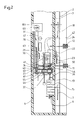
- the tachograph shown in Figures 1 and 2 has an essentially cuboid housing 1, the cross-sectional shape of which can be seen in Figure 2.
- the housing 1 is covered on its front by a transparent pane 2 made of glass or plastic. Behind it a dial 3 with several scales over which hands play.
- the dial comprises a tachometer scale 5, which is associated with a pointer 7 driven by a speedometer 6 (FIG. 2). Furthermore, the dial 3 comprises symbols 8 (FIG. 1), each of which is assigned to a time group switch 11 or 12. At these switches, two drivers of a motor vehicle can alternately set their working hours, rest times and the like in a conventional manner. Finally, the dial 3 comprises slots 13, 14, on which the indicating digits of an odometer 15 or a trip odometer 16 are visible in a known manner. The counters are behind the dial 3 and are permanently connected to the one-piece, indivisible housing 1.
- the dial 3 further comprises a speed scale 17 with a pointer 18 of a speed meter which is also accommodated in the housing 1 (not shown).
- Clock hands 22, 23 can be rotated over a dial 21 of a time clock with clockwork 24, offset laterally to the tachometer scale 5.
- the clockwork 24 of the time clock is also fixed in the housing 1.
- a plate 28 is also pivotally mounted about an axis 27, on which a diagram disk carrier 29 driven by the clockwork 24 is arranged.
- the diagram disk carrier 29 serves in a manner known per se to accommodate one or more diagram disks, of which only one diagram disk 31 is shown in the drawing.
- the measured values supplied by the instruments in the housing 1 are also recorded in a conventional manner in the operating state of the tachograph.
- the instruments comprise registration devices, which in turn are connected in a known manner with writing pens which mark the surface of the diagram disc (s).
- the time group switches 11, 12 are particularly provided with such registration devices.
- a pinion 42 visible in FIG. 2 is rotated via the time group switch 11.
- the pinion 42 meshes with a rack 41 which is rigidly connected to the housing 40 of a pen 34.
- the pen housing 40 is displaceable on a guide formed by two rods 36, 37 across the plane of the diagram disk 31.
- the stylus 34 can be set in such a way that it records a circular trace of a certain radius concentrically to the axis of rotation 30 of the diagram disc 31 on the diagram disc 31.
- Additional pens 43, 44 are assigned to the speedometer 6 and the odometer 15 and are connected to these components by means of appropriate bridge members.
- the spatial links between the measuring instruments and the diagram disk 31 are bridged by the bridge members, for example toothed racks corresponding to the toothed rack 41, so that the measured values displayed by the instruments are correctly recorded there.
- the chart support 29 can be pivoted upward out of the housing when the tachograph is inoperative, where chart charts 31 can be exchanged in a convenient manner.
- the diagram disc carrier 29 with the diagram disc (s) attached to it lies in a chamber 47 of the housing 1.
- the pivot axis 27 of the plate 28 runs parallel to the axis of the tachometer pointer 7, the plate 28 is therefore pivoted in one plane. which is essentially parallel to the dial 3 on the front of the housing 1.
- the disc 2 and with it the housing 1 is inclined obliquely to the horizontal, so that the driver of a motor vehicle can easily see the dial 3.
- the plate 28 can be pivoted out of the housing 1 in a correspondingly inclined plane.
- the pivot axis 27 does not have to run parallel to the axis of rotation of the speedometer pointer 7. In this case, it can also be achieved with an obliquely arranged housing that the plate 28 and the chart support 29 are movable in a substantially vertical plane.
- the chamber 47 receiving the diagram disk carrier 29 lies approximately in the middle between the scales 5, 17 of the dial 3 and behind the display devices of the measuring instruments assigned to these pointers. In the operating state, therefore, the diagram disk carrier 29 is laterally offset with respect to the tachometer scale 5 and the speed scale 17. This lateral offset is not absolutely necessary.
- the axis of rotation 27 can also be arranged in such a way that the chart carrier 29 lies behind the display device 6 of the tachometer in the operating state of the tachograph without lateral offset, for example such that the axis of rotation 30 of the chart carrier 29 is essentially coaxial with the pointer shaft of the pointer 7 runs.
- the movement of the diagram disk carrier takes place in a plane which runs essentially parallel to the plane of the diagram disk.
- the diagram disk carrier 29 is driven from the clockwork 24 of the time clock via a shaft 50.
- a bushing 55 is rotatably arranged on the swivel axis 27 of the plate 28 carrying the diagram disk carrier 29 and has a bevel gear 56 at its end on the right in FIG. 2.
- This bevel gear 56 meshes with the bevel gear 57 ( Figure 1), which is driven via the shaft 50 to the clockwork 24 with precise timing.
- the socket also has at its left end in FIG. 2 there is a gear 61 (FIG. 2) which meshes with a gear 62 (FIG. 1) mounted on the plate 28.
- the diagram disk support 29, which is connected to it in a rotationally fixed manner is driven in a timely manner via a further toothed wheel 63. Due to this gear connection, the plate 28 can be pivoted about the axis 27 without impairing the engagement with the clockwork 24 and the timely drive. When pivoting the plate 28 back into the chamber 47, a backlash of this gear train between the timer and the chart carrier is eliminated.
- a plate 101 is connected to the plate 28, projecting vertically therefrom, which is pivoted together with the plate 28 and, in the operating state of the tachograph, tightly closes the chamber 47 which receives the diagram disk carrier 29.
- a lock 102 with a removable key 103 is arranged on the lid 101.
- the lock 102 is designed in a known manner as a locking lock so that when the cover 101 is pivoted into the closed position it snaps in without turning the key 103 and closes the cover.
- the key 103 only has to be inserted into the lock 102 and turned to open it.
- the plate 28 can also be assigned a second latching device in a manner known per se and therefore not specifically shown, which detects the plate in the inoperative state of the tachograph in its position pivoted upwards out of the housing, so that diagram disks 31 can be exchanged comfortably can without having to hold the plate 28.
- the cover 101 When closing, the cover 101 not only covers the chamber 47 of the housing 1 receiving the diagram disk carrier 29 and the diagram disks 31, but also additional functional parts of the tachograph. These functional parts include in particular an adjustment button 104 for the time clock.
- the button 104 which is indicated schematically in FIG. 1, is mounted on the side of the plate 28 facing away from the diagram disk 31. As can also be seen in FIG. 1, it is connected to gear wheel 62 via gear wheels, so that the clock can be set when knob 104 is turned.
- the adjusting button 104 is no longer accessible.
- a coding switch 105 and a socket 106 are also fixedly arranged on a carrier 107 as further functional parts of the tachograph (as indicated schematically in FIG. 1). Electrical lines can be arranged on two lugs 108, 109 of the socket 106. As is known per se, the correctness of a measurement can be checked at the correspondingly set coding switch 105, which is usually additionally sealed, at the socket 106, or a corresponding calibration can be carried out. When the cover 101 is open, the socket 106 is accessible without hindrance. When the cover 101 is closed, the socket 106 and the coding switch 107 are also covered inaccessibly.
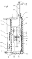
- FIGS. 3 to 5 show an embodiment of a tachograph modified from FIGS. 1 and 2.
- FIGS. 3 to 5 are corresponding parts with the same reference numerals as in Figures 1 and 2.
- the plate 28 carrying the diagram disk carrier 29 and the diagram disk (s) cannot be pivoted with the cover 101, but rather can be slid upwards out of the housing 1.
- the plate 28 (cf. FIG. 4) is displaceably mounted on both sides in slide guides 111, the center lines of which are indicated by dash-dotted lines in FIG. 3 and are also identified by the reference number 111.
- the writing area S in the embodiment according to FIGS. 3 to 5 is rotated by 90 ° with respect to the writing area S in the embodiment according to FIGS. 1 and 2 and runs parallel to the direction of slide of the plate 28 (FIG. 3).
- the chart support 29 can also lie directly behind the tachometer scale 5 without any lateral offset.
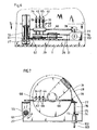
- FIG. 5 shows the diagram disk carrier 28 in solid lines in its position pushed upwards out of the tachograph housing 1.
- the operating position with inserted diagram chart support 29 is shown in dashed lines in FIG.
- a bevel gear 112 driving the diagram disk carrier 29 is connected in a rotationally fixed manner to a rod 113.
- the rod 113 is slidably guided (telescoping) in a pipe 114 running parallel to it.
- a pin 115 projects laterally from the rod 113 and extends into an axially extending slot 119 in the tube 114.
- the rod 113 and the tube 114 are connected to one another in a rotationally fixed but slidable manner.
- a bevel gear 116 which meshes with the bevel gear 117.
- the bevel gear 117 is driven by the clockwork 24 via a shaft 118.
- the diagram disk carrier 29 is constantly in drive connection with the clockwork 24, even if it is pushed out of the housing 1 of the tachograph when the tachograph is out of operation.
- the writing pens 34, 43, 44 are slidably mounted on a slide part 65 and are biased by springs 39 onto the diagram disk 31.
- the tips of the writing pens 34, 43, 44 must be lifted off the diagram disk 31 in order to avoid undesired recording tracks on the diagram disk.
- a relatively elongated, eccentric cam 67 is mounted on a shaft 66 mounted in the housing 1 Shaft 66 by means of protrusions 68 (FIG. 7) protruding from the pens lifts the pens from the chart disc 31, so that the chart disc 31 together with the plate 28 can now be moved out of the chamber 47 without the pens providing undesired traces of writing will.
- the shaft 66 and thus the cam 67 can be rotated in various ways for the purpose of lifting the pens.
- the twist could be derived from the pivoting or sliding movement of the plate 28.
- the shaft 66 can be adjusted simultaneously with the drive of this device by the necessary angular range in order to lift the pens off the diagram disk.
- the lifting movement of the pens is derived from the lock 102 with the associated key 103.
- the lock 102 serves to lock a wall part connected to the plate 28 which, when the chamber 47 is closed, can lie approximately in the plane of the front wall of the housing 1 formed by the disk 2.
- a coupling part 74 which is fixedly connected to a rotatable lock part 73, positively engages in a corresponding slot 75 on the end face of a rotatably mounted shaft 76 as soon as the wall part mentioned is closed.
- the shaft 76 can thus be rotated by a rotary movement of the key 103.
- the shaft 76 carries a bevel gear 77 which meshes with a bevel gear 78 seated on the shaft 66.
Claims (20)
- Tachygraphe pour véhicules automobiles comportant un boîtier (1) logeant des instruments de mesure comprenant un tachymètre (6), des compteurs de distance (15, 16), une horloge (24), des instruments de mesure comportant des installations d'enregistrement et d'affichage avec des stylets (34, 43, 44) reliés aux installations d'enregistrement, avec au moins un cadran principal (5) prévu sur la face avant du boîtier pour être associé aux installations d'affichage et portant les échelles du tachymètre, des compteurs de distance ainsi que des groupes de temps (8), et un support de disque d'enregistrement (29), entraîné en rotation par l'horloge pour enregistrer sur au moins un disque d'enregistrement (13) sur lequel les stylets inscrivent les grandeurs de mesure fournies par les instruments de mesure, les installations d'enregistrement étant toujours reliées de manière solidaire aux installations d'affichage, le support de disque d'enregistrement étant placé dans une chambre (47) distincte, séparée géométriquement du cadran dans le boîtier, les stylets étant également décalés par rapport au cadran, au-dessus des disques d'enregistrement en étant reliés aux installations d'enregistrement et le support de disque d'enregistrement étant mobile par rapport aux installations d'enregistrement et d'affichage solidaire du boîtier des instruments de mesure pour permettre le changement de disque d'enregistrement, tachygraphe caractérisé en ce que l'horloge (24) est montée fixe dans le boîtier (1) par rapport au support mobile (29) du disque d'enregistrement, et est reliée en permanence par une transmission (54-61) au support mobile de disque d'enregistrement et en ce que le support de disque d'enregistrement (29) est mobile dans un plan pour permettre le changement des disques d'enregistrement, plan qui est principalement parallèle au cadran principal (5) et par rapport aux disques d'enregistrement portés par le support à disque d'enregistrement.
- Tachygraphe selon la revendication 1, caractérisé en ce que les stylets (34, 43, 44) peuvent être relevés par rapport au plan du disque d'enregistrement (31) pour permettre le remplacement des disques.
- Tachygraphe selon la revendication 2, caractérisé en ce qu'un mouvement du support de disque d'enregistrement (29) par rapport aux installations d'enregistrement et d'affichage est déclenché automatiquement par le soulèvement des stylets (34, 43, 44).
- Tachygraphe selon la revendication 2, caractérisé en ce que les tiges d'écriture (34, 43, 44) peuvent être soulevées par l'actionnement d'une serrure (102) fermant la chambre.
- Tachygraphe selon la revendication 1, caractérisé en ce que le support de disque d'enregistrement (29) est monté sur une plaque (28) coulissante par rapport au boîtier (1).
- Tachygraphe selon la revendication 1, caractérisé en ce que le support de disque d'enregistrement (29) est monté sur une plaque (28) portée de manière pivotante par rapport au boîtier (1), et cette plaque peut être basculée dans ou en dehors de la chambre (47).
- Tachygraphe selon l'une des revendications précédentes, caractérisé en ce que les installations d'affichage et d'enregistrement sont réunies dans un bloc de boîtier susceptible d'être plombé et ce bloc se place dans le boîtier (1).
- Tachygraphe selon la revendication 1, caractérisé en ce que la chambre (47) et le support de disque d'enregistrement (29) sont prévus géométriquement derrière le tachymètre (6) et son aiguille lorsque le tachygraphe est en position de fonctionnement et le support de disque d'enregistrement (29) peut sortir du boîtier (1) par le haut.
- Tachygraphe selon la revendication 8, caractérisé en ce que le support de disque d'enregistrement (29) est monté dans le boîtier (1) de manière à pivoter autour d'un axe (27) et pour un tachymètre (6) restant en position fixe, ce support peut basculer par le haut en dehors du boîtier (1).
- Tachygraphe selon la revendication 8, caractérisé en ce que le support de disque d'enregistrement (29) est coulissant dans le boîtier (2) et peut sortir par le haut du boîtier tout en laissant le tachymètre (6) en position fixe.
- Tachygraphe selon la revendication 8, caractérisé en ce que le support de disque d'enregistrement (29) est mobile dans un plan essentiellement vertical.
- Tachygraphe selon la revendication 8, caractérisé en ce que l'axe de rotation (29) du support de disque d'enregistrement est pratiquement parallèle à l'arbre de l'aiguille (7) du tachymètre (6) lorsque le tachygraphe est en position de fonctionnement.
- Tachygraphe selon la revendication 8, caractérisé en ce que la chambre (47) qui loge le support de disque d'enregistrement (29) peut être fermé par un couvercle à serrure (101).
- Tachygraphe selon la revendication 13, caractérisé en ce que le couvercle (101) est prévu sur une plaque (28) qui porte le support de disque d'enregistrement (29).
- Tachygraphe selon la revendication 13, caractérisé en ce que le couvercle (101) recouvre en même temps d'autres points de fonctionnement (105, 106) du tachygraphe, notamment un bouton de réglage (104) pour l'horloge (24).
- Tachygraphe selon la revendication 15, caractérisé en ce que le bouton de réglage (104) de l'horloge (24) est monté sur une plaque (24) qui porte le support de disque d'enregistrement (29).
- Tachygraphe selon la revendication 15, caractérisé en ce que les autres pièces fonctionnelles comprennent un commutateur de codage (105) et une douille de connexion (106).
- Tachygraphe selon la revendication 9, caractérisé par une transmission (50, 57, 62, 63) reliant l'horloge (24) en permanence avec le support de disque d'enregistrement (29), pivotant, et cette transmission comprend une roue de transmission (56) coaxiale à l'axe de pivotement (27).
- Tachygraphe selon la revendication 10, caractérisé en ce que la transmission (112, 116, 117) qui relie en permanence l'horloge (24) avec le support de disque d'enregistrement (29) monté coulissant, comprend une liaison télescopique (113, 114, 115) solidaire en rotation.
- Tachygraphe selon la revendication 8, caractérisé en ce que le dispositif de mesure de vitesse (6) et le compteur de distance (15, 16) ainsi que les compteurs de distance (15, 16) avec le tableau chiffré principal (5) et les aiguilles (7, 18, 22, 23) ainsi que les installations d'enregistrement, sont logés avec les stylets (34, 43, 44) dans un boîtier (1), commun, fixe, et qui ne peut être divisé.
Applications Claiming Priority (4)
| Application Number | Priority Date | Filing Date | Title |
|---|---|---|---|
| DE19863618109 DE3618109A1 (de) | 1986-05-30 | 1986-05-30 | Fahrtschreiber fuer kraftfahrzeuge |
| DE3618109 | 1986-05-30 | ||
| DE3626892 | 1986-08-08 | ||
| DE19863626892 DE3626892A1 (de) | 1986-08-08 | 1986-08-08 | Fahrtschreiber fuer kraftfahrzeuge |
Publications (3)
| Publication Number | Publication Date |
|---|---|
| EP0247550A2 EP0247550A2 (fr) | 1987-12-02 |
| EP0247550A3 EP0247550A3 (en) | 1988-05-04 |
| EP0247550B1 true EP0247550B1 (fr) | 1992-09-16 |
Family
ID=25844186
Family Applications (1)
| Application Number | Title | Priority Date | Filing Date |
|---|---|---|---|
| EP87107539A Expired - Lifetime EP0247550B1 (fr) | 1986-05-30 | 1987-05-23 | Tachygraphe pour véhicules à moteur |
Country Status (3)
| Country | Link |
|---|---|
| US (1) | US4862191A (fr) |
| EP (1) | EP0247550B1 (fr) |
| ES (1) | ES2034986T3 (fr) |
Families Citing this family (6)
| Publication number | Priority date | Publication date | Assignee | Title |
|---|---|---|---|---|
| DE8805789U1 (fr) * | 1988-05-02 | 1988-07-14 | Mannesmann Kienzle Gmbh, 7730 Villingen-Schwenningen, De | |
| DE3838280A1 (de) * | 1988-11-11 | 1990-05-17 | Mannesmann Kienzle Gmbh | Fahrtschreiber mit zeitabhaengig angetriebenen mitnahmemitteln fuer als aufzeichnungstraeger dienende diagrammscheiben |
| DE9317101U1 (de) * | 1993-11-09 | 1994-03-03 | Mannesmann Kienzle Gmbh | Kraftfahrzeug mit einem Fahrtschreiber |
| CH689987A5 (fr) * | 1994-04-19 | 2000-02-29 | Smh Management Services Ag | Dispositif compact d'affichage permettant la lecture de plusieurs mesures et tableau de bord compact comportant un tel dispositif. |
| DE29610675U1 (de) * | 1996-06-18 | 1996-08-29 | Vdo Schindling | Fahrtschreiber mit einem Laufwerk für den zeitabhängigen Antrieb von als Aufzeichnungsträger dienenden Diagrammscheiben |
| DE20004685U1 (de) * | 2000-03-14 | 2000-06-29 | Mannesmann Vdo Ag | Anordnung zum Festspannen eines Diagrammscheibenbündels auf einer vom Registrierlaufwerk eines Fahrtschreibers zeitsynchron angetriebenen Aufnahme |
Family Cites Families (15)
| Publication number | Priority date | Publication date | Assignee | Title |
|---|---|---|---|---|
| US1514524A (en) * | 1922-10-18 | 1924-11-04 | Taylor Instrument Co | Recording instrument |
| US1619241A (en) * | 1926-06-21 | 1927-03-01 | Republic Flow Meters Co | Pen lifter for recording instruments |
| US1910361A (en) * | 1930-08-08 | 1933-05-23 | Permutit Co | Chart recording meter |
| US2152333A (en) * | 1937-06-18 | 1939-03-28 | Republic Flow Meters Co | Recording instrument |
| US2204046A (en) * | 1939-04-28 | 1940-06-11 | James H Melville | Pen lifting attachment for recording meters |
| US2873163A (en) * | 1954-06-16 | 1959-02-10 | Bailey Meter Co | Pen lifting and chart support for recording meters |
| BE555407A (fr) * | 1956-03-02 | |||
| US3281856A (en) * | 1961-04-10 | 1966-10-25 | Litton Systems Inc | Microwave recording upon a deformable medium |
| DE1548685B1 (de) * | 1966-01-13 | 1970-07-30 | Kienzle Apparate Gmbh | Fahrtschreiber fuer Kraftfahrzeuge |
| DE2237087B2 (de) * | 1972-07-28 | 1980-03-13 | Kienzle Apparate Gmbh, 7730 Villingen-Schwenningen | Fahrtschreiber |
| DE2411515C2 (de) * | 1974-03-11 | 1985-03-07 | Moto Meter Ag, 7250 Leonberg | Fahrtschreiber mit Meß- und Schreibwerken |
| LU72703A1 (fr) * | 1974-07-13 | 1975-10-08 | ||
| DE2917329A1 (de) * | 1979-04-28 | 1980-11-06 | Kienzle Apparate Gmbh | Registriergeraet |
| DE3046118A1 (de) * | 1980-12-06 | 1982-07-22 | Kienzle Apparate Gmbh, 7730 Villingen-Schwenningen | Ausbildung eines gehaeuses, insb. fuer fahrtschreiber, und eines schwenkbar an dem gehaeuse angeordneten deckels |
| DE3142677A1 (de) * | 1981-10-28 | 1983-05-05 | Kienzle Apparate Gmbh, 7730 Villingen-Schwenningen | Fahrtschreiber |
-
1987
- 1987-05-23 EP EP87107539A patent/EP0247550B1/fr not_active Expired - Lifetime
- 1987-05-23 ES ES198787107539T patent/ES2034986T3/es not_active Expired - Lifetime
-
1988
- 1988-08-19 US US07/235,819 patent/US4862191A/en not_active Expired - Fee Related
Also Published As
| Publication number | Publication date |
|---|---|
| US4862191A (en) | 1989-08-29 |
| EP0247550A3 (en) | 1988-05-04 |
| ES2034986T3 (es) | 1993-04-16 |
| EP0247550A2 (fr) | 1987-12-02 |
Similar Documents
| Publication | Publication Date | Title |
|---|---|---|
| EP0012223B1 (fr) | Enregistreur de route | |
| EP0247550B1 (fr) | Tachygraphe pour véhicules à moteur | |
| DE2536346C3 (de) | Vorrichtung zur Anzeige durchzuführender Wartungsarbeiten an einem Fahrzeug | |
| DE4315833A1 (de) | Fahrtschreiber für Kraftfahrzeuge | |
| DE1548685B1 (de) | Fahrtschreiber fuer Kraftfahrzeuge | |
| DE7811664U1 (de) | Geraet zum anzeigen von messwerten | |
| DE2411515C2 (de) | Fahrtschreiber mit Meß- und Schreibwerken | |
| DE102016124958B4 (de) | Anzeigevorrichtung für einen Türschließer mit verstellbarer Schließkraft sowie Türschließer | |
| DE1266036B (de) | Fahrtschreiber fuer Kraftfahrzeuge | |
| DE3618109C2 (fr) | ||
| DE1268889C2 (de) | Fahrtschreiber mit einem im wesentlichen zylindrischen Einbaugehaeuse | |
| EP0800151B1 (fr) | Liaison d'entraínement pour un dispositif d'enregistrement de tachygraphe | |
| DE3626892A1 (de) | Fahrtschreiber fuer kraftfahrzeuge | |
| DE3730215C1 (de) | Fahrtschreiber fuer Kraftfahrzeuge | |
| DE2336058B2 (de) | Vorrichtung zum genauen einstellen und messen von winkeln an zeichenmaschinen | |
| EP0306907B1 (fr) | Tachygraphe pour véhicules automobiles | |
| EP0255934B1 (fr) | Tachygraphe pour voitures | |
| EP0368219B1 (fr) | Enregistreur de route avec des moyens d'entraînement actionnés en temps pour des portes-diagrammes servant comme support d'enregistrement | |
| DE1056401B (de) | Tachograph | |
| DE938339C (de) | Tachograph fuer durch Maschinenkraft angetriebene Fahrzeuge | |
| DE3639625A1 (de) | Fahrtschreiber | |
| DE2414231C2 (de) | Tachograph | |
| DE1955039C3 (de) | Fahrtschreiber | |
| DE2227726A1 (de) | Zeitabhängig aufzeichnendes Registriergerät | |
| EP0184142B1 (fr) | Interrupteur avec contact à frottement pour un dispositif de signal dans un tachographe |
Legal Events
| Date | Code | Title | Description |
|---|---|---|---|
| PUAI | Public reference made under article 153(3) epc to a published international application that has entered the european phase |
Free format text: ORIGINAL CODE: 0009012 |
|
| AK | Designated contracting states |
Kind code of ref document: A2 Designated state(s): ES FR GB IT SE |
|
| PUAL | Search report despatched |
Free format text: ORIGINAL CODE: 0009013 |
|
| AK | Designated contracting states |
Kind code of ref document: A3 Designated state(s): ES FR GB IT SE |
|
| 17P | Request for examination filed |
Effective date: 19880810 |
|
| 17Q | First examination report despatched |
Effective date: 19900928 |
|
| GRAA | (expected) grant |
Free format text: ORIGINAL CODE: 0009210 |
|
| AK | Designated contracting states |
Kind code of ref document: B1 Designated state(s): ES FR GB IT SE |
|
| GBT | Gb: translation of ep patent filed (gb section 77(6)(a)/1977) | ||
| ET | Fr: translation filed | ||
| ITF | It: translation for a ep patent filed |
Owner name: STUDIO JAUMANN |
|
| REG | Reference to a national code |
Ref country code: ES Ref legal event code: FG2A Ref document number: 2034986 Country of ref document: ES Kind code of ref document: T3 |
|
| PLBI | Opposition filed |
Free format text: ORIGINAL CODE: 0009260 |
|
| 26 | Opposition filed |
Opponent name: MANNESMANN KIENZLE GMBH Effective date: 19930615 |
|
| PLBN | Opposition rejected |
Free format text: ORIGINAL CODE: 0009273 |
|
| STAA | Information on the status of an ep patent application or granted ep patent |
Free format text: STATUS: OPPOSITION REJECTED |
|
| 27O | Opposition rejected |
Effective date: 19940520 |
|
| EAL | Se: european patent in force in sweden |
Ref document number: 87107539.6 |
|
| PGFP | Annual fee paid to national office [announced via postgrant information from national office to epo] |
Ref country code: ES Payment date: 19960531 Year of fee payment: 10 |
|
| PGFP | Annual fee paid to national office [announced via postgrant information from national office to epo] |
Ref country code: GB Payment date: 19970506 Year of fee payment: 11 |
|
| PGFP | Annual fee paid to national office [announced via postgrant information from national office to epo] |
Ref country code: FR Payment date: 19970523 Year of fee payment: 11 |
|
| PG25 | Lapsed in a contracting state [announced via postgrant information from national office to epo] |
Ref country code: ES Free format text: LAPSE BECAUSE OF NON-PAYMENT OF DUE FEES Effective date: 19970524 |
|
| PGFP | Annual fee paid to national office [announced via postgrant information from national office to epo] |
Ref country code: SE Payment date: 19970526 Year of fee payment: 11 |
|
| PG25 | Lapsed in a contracting state [announced via postgrant information from national office to epo] |
Ref country code: GB Free format text: LAPSE BECAUSE OF NON-PAYMENT OF DUE FEES Effective date: 19980523 |
|
| PG25 | Lapsed in a contracting state [announced via postgrant information from national office to epo] |
Ref country code: SE Free format text: LAPSE BECAUSE OF NON-PAYMENT OF DUE FEES Effective date: 19980524 |
|
| PG25 | Lapsed in a contracting state [announced via postgrant information from national office to epo] |
Ref country code: FR Free format text: LAPSE BECAUSE OF NON-PAYMENT OF DUE FEES Effective date: 19980531 |
|
| GBPC | Gb: european patent ceased through non-payment of renewal fee |
Effective date: 19980523 |
|
| EUG | Se: european patent has lapsed |
Ref document number: 87107539.6 |
|
| REG | Reference to a national code |
Ref country code: FR Ref legal event code: ST |
|
| REG | Reference to a national code |
Ref country code: ES Ref legal event code: FD2A Effective date: 19990301 |
|
| PG25 | Lapsed in a contracting state [announced via postgrant information from national office to epo] |
Ref country code: IT Free format text: LAPSE BECAUSE OF NON-PAYMENT OF DUE FEES;WARNING: LAPSES OF ITALIAN PATENTS WITH EFFECTIVE DATE BEFORE 2007 MAY HAVE OCCURRED AT ANY TIME BEFORE 2007. THE CORRECT EFFECTIVE DATE MAY BE DIFFERENT FROM THE ONE RECORDED. Effective date: 20050523 |