EP0247550B1 - Tachograph for motor vehicles - Google Patents
Tachograph for motor vehicles Download PDFInfo
- Publication number
- EP0247550B1 EP0247550B1 EP87107539A EP87107539A EP0247550B1 EP 0247550 B1 EP0247550 B1 EP 0247550B1 EP 87107539 A EP87107539 A EP 87107539A EP 87107539 A EP87107539 A EP 87107539A EP 0247550 B1 EP0247550 B1 EP 0247550B1
- Authority
- EP
- European Patent Office
- Prior art keywords
- speed
- time chart
- housing
- tachograph
- carrier
- Prior art date
- Legal status (The legal status is an assumption and is not a legal conclusion. Google has not performed a legal analysis and makes no representation as to the accuracy of the status listed.)
- Expired - Lifetime
Links
Images


Classifications
-
- G—PHYSICS
- G01—MEASURING; TESTING
- G01P—MEASURING LINEAR OR ANGULAR SPEED, ACCELERATION, DECELERATION, OR SHOCK; INDICATING PRESENCE, ABSENCE, OR DIRECTION, OF MOVEMENT
- G01P1/00—Details of instruments
- G01P1/12—Recording devices
- G01P1/122—Speed recorders
- G01P1/125—Speed recorders with recording discs
-
- G—PHYSICS
- G07—CHECKING-DEVICES
- G07C—TIME OR ATTENDANCE REGISTERS; REGISTERING OR INDICATING THE WORKING OF MACHINES; GENERATING RANDOM NUMBERS; VOTING OR LOTTERY APPARATUS; ARRANGEMENTS, SYSTEMS OR APPARATUS FOR CHECKING NOT PROVIDED FOR ELSEWHERE
- G07C5/00—Registering or indicating the working of vehicles
- G07C5/08—Registering or indicating performance data other than driving, working, idle, or waiting time, with or without registering driving, working, idle or waiting time
- G07C5/12—Registering or indicating performance data other than driving, working, idle, or waiting time, with or without registering driving, working, idle or waiting time in graphical form
Definitions
- the invention relates to a tachograph for motor vehicles according to the preamble of claim 1.
- the known tachographs of this type have a substantially cylindrical housing which consists of two housing parts, namely a main housing and a cover housing, the cover housing being arranged in a foldable manner on the main housing and on its free end face display devices with a Main dial for the measuring instruments housed both in the main housing and in the cover housing.
- the cover housing contains the timer and the diagram disk carrier driven by it. To replace a diagram disc, the cover housing must be folded down from the main housing, and the actual replacement process can usually only be carried out with difficulty because of the small space available between the main and cover housing.
- the display devices arranged in the cover housing for example a tachometer pointer and the odometer, are driven from the stationary main housing, flexible drive connections are required which are complex to manufacture and prone to failure.
- the hinged lid housing with its main dial leaves practically no scope for the design of a motor vehicle dashboard, since essential display devices are already provided on the front side of the hinged, cylindrical lid housing.
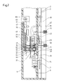
- the tachograph shown in Figures 1 and 2 has an essentially cuboid housing 1, the cross-sectional shape of which can be seen in Figure 2.
- the housing 1 is covered on its front by a transparent pane 2 made of glass or plastic. Behind it a dial 3 with several scales over which hands play.
- the dial comprises a tachometer scale 5, which is associated with a pointer 7 driven by a speedometer 6 (FIG. 2). Furthermore, the dial 3 comprises symbols 8 (FIG. 1), each of which is assigned to a time group switch 11 or 12. At these switches, two drivers of a motor vehicle can alternately set their working hours, rest times and the like in a conventional manner. Finally, the dial 3 comprises slots 13, 14, on which the indicating digits of an odometer 15 or a trip odometer 16 are visible in a known manner. The counters are behind the dial 3 and are permanently connected to the one-piece, indivisible housing 1.
- the dial 3 further comprises a speed scale 17 with a pointer 18 of a speed meter which is also accommodated in the housing 1 (not shown).
- Clock hands 22, 23 can be rotated over a dial 21 of a time clock with clockwork 24, offset laterally to the tachometer scale 5.
- the clockwork 24 of the time clock is also fixed in the housing 1.
- a plate 28 is also pivotally mounted about an axis 27, on which a diagram disk carrier 29 driven by the clockwork 24 is arranged.
- the diagram disk carrier 29 serves in a manner known per se to accommodate one or more diagram disks, of which only one diagram disk 31 is shown in the drawing.
- the measured values supplied by the instruments in the housing 1 are also recorded in a conventional manner in the operating state of the tachograph.
- the instruments comprise registration devices, which in turn are connected in a known manner with writing pens which mark the surface of the diagram disc (s).
- the time group switches 11, 12 are particularly provided with such registration devices.
- a pinion 42 visible in FIG. 2 is rotated via the time group switch 11.
- the pinion 42 meshes with a rack 41 which is rigidly connected to the housing 40 of a pen 34.
- the pen housing 40 is displaceable on a guide formed by two rods 36, 37 across the plane of the diagram disk 31.
- the stylus 34 can be set in such a way that it records a circular trace of a certain radius concentrically to the axis of rotation 30 of the diagram disc 31 on the diagram disc 31.
- Additional pens 43, 44 are assigned to the speedometer 6 and the odometer 15 and are connected to these components by means of appropriate bridge members.
- the spatial links between the measuring instruments and the diagram disk 31 are bridged by the bridge members, for example toothed racks corresponding to the toothed rack 41, so that the measured values displayed by the instruments are correctly recorded there.
- the chart support 29 can be pivoted upward out of the housing when the tachograph is inoperative, where chart charts 31 can be exchanged in a convenient manner.
- the diagram disc carrier 29 with the diagram disc (s) attached to it lies in a chamber 47 of the housing 1.
- the pivot axis 27 of the plate 28 runs parallel to the axis of the tachometer pointer 7, the plate 28 is therefore pivoted in one plane. which is essentially parallel to the dial 3 on the front of the housing 1.
- the disc 2 and with it the housing 1 is inclined obliquely to the horizontal, so that the driver of a motor vehicle can easily see the dial 3.
- the plate 28 can be pivoted out of the housing 1 in a correspondingly inclined plane.
- the pivot axis 27 does not have to run parallel to the axis of rotation of the speedometer pointer 7. In this case, it can also be achieved with an obliquely arranged housing that the plate 28 and the chart support 29 are movable in a substantially vertical plane.
- the chamber 47 receiving the diagram disk carrier 29 lies approximately in the middle between the scales 5, 17 of the dial 3 and behind the display devices of the measuring instruments assigned to these pointers. In the operating state, therefore, the diagram disk carrier 29 is laterally offset with respect to the tachometer scale 5 and the speed scale 17. This lateral offset is not absolutely necessary.
- the axis of rotation 27 can also be arranged in such a way that the chart carrier 29 lies behind the display device 6 of the tachometer in the operating state of the tachograph without lateral offset, for example such that the axis of rotation 30 of the chart carrier 29 is essentially coaxial with the pointer shaft of the pointer 7 runs.
- the movement of the diagram disk carrier takes place in a plane which runs essentially parallel to the plane of the diagram disk.
- the diagram disk carrier 29 is driven from the clockwork 24 of the time clock via a shaft 50.
- a bushing 55 is rotatably arranged on the swivel axis 27 of the plate 28 carrying the diagram disk carrier 29 and has a bevel gear 56 at its end on the right in FIG. 2.
- This bevel gear 56 meshes with the bevel gear 57 ( Figure 1), which is driven via the shaft 50 to the clockwork 24 with precise timing.
- the socket also has at its left end in FIG. 2 there is a gear 61 (FIG. 2) which meshes with a gear 62 (FIG. 1) mounted on the plate 28.
- the diagram disk support 29, which is connected to it in a rotationally fixed manner is driven in a timely manner via a further toothed wheel 63. Due to this gear connection, the plate 28 can be pivoted about the axis 27 without impairing the engagement with the clockwork 24 and the timely drive. When pivoting the plate 28 back into the chamber 47, a backlash of this gear train between the timer and the chart carrier is eliminated.
- a plate 101 is connected to the plate 28, projecting vertically therefrom, which is pivoted together with the plate 28 and, in the operating state of the tachograph, tightly closes the chamber 47 which receives the diagram disk carrier 29.
- a lock 102 with a removable key 103 is arranged on the lid 101.
- the lock 102 is designed in a known manner as a locking lock so that when the cover 101 is pivoted into the closed position it snaps in without turning the key 103 and closes the cover.
- the key 103 only has to be inserted into the lock 102 and turned to open it.
- the plate 28 can also be assigned a second latching device in a manner known per se and therefore not specifically shown, which detects the plate in the inoperative state of the tachograph in its position pivoted upwards out of the housing, so that diagram disks 31 can be exchanged comfortably can without having to hold the plate 28.
- the cover 101 When closing, the cover 101 not only covers the chamber 47 of the housing 1 receiving the diagram disk carrier 29 and the diagram disks 31, but also additional functional parts of the tachograph. These functional parts include in particular an adjustment button 104 for the time clock.
- the button 104 which is indicated schematically in FIG. 1, is mounted on the side of the plate 28 facing away from the diagram disk 31. As can also be seen in FIG. 1, it is connected to gear wheel 62 via gear wheels, so that the clock can be set when knob 104 is turned.
- the adjusting button 104 is no longer accessible.
- a coding switch 105 and a socket 106 are also fixedly arranged on a carrier 107 as further functional parts of the tachograph (as indicated schematically in FIG. 1). Electrical lines can be arranged on two lugs 108, 109 of the socket 106. As is known per se, the correctness of a measurement can be checked at the correspondingly set coding switch 105, which is usually additionally sealed, at the socket 106, or a corresponding calibration can be carried out. When the cover 101 is open, the socket 106 is accessible without hindrance. When the cover 101 is closed, the socket 106 and the coding switch 107 are also covered inaccessibly.
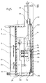
- FIGS. 3 to 5 show an embodiment of a tachograph modified from FIGS. 1 and 2.
- FIGS. 3 to 5 are corresponding parts with the same reference numerals as in Figures 1 and 2.
- the plate 28 carrying the diagram disk carrier 29 and the diagram disk (s) cannot be pivoted with the cover 101, but rather can be slid upwards out of the housing 1.
- the plate 28 (cf. FIG. 4) is displaceably mounted on both sides in slide guides 111, the center lines of which are indicated by dash-dotted lines in FIG. 3 and are also identified by the reference number 111.
- the writing area S in the embodiment according to FIGS. 3 to 5 is rotated by 90 ° with respect to the writing area S in the embodiment according to FIGS. 1 and 2 and runs parallel to the direction of slide of the plate 28 (FIG. 3).
- the chart support 29 can also lie directly behind the tachometer scale 5 without any lateral offset.
- FIG. 5 shows the diagram disk carrier 28 in solid lines in its position pushed upwards out of the tachograph housing 1.
- the operating position with inserted diagram chart support 29 is shown in dashed lines in FIG.
- a bevel gear 112 driving the diagram disk carrier 29 is connected in a rotationally fixed manner to a rod 113.
- the rod 113 is slidably guided (telescoping) in a pipe 114 running parallel to it.
- a pin 115 projects laterally from the rod 113 and extends into an axially extending slot 119 in the tube 114.
- the rod 113 and the tube 114 are connected to one another in a rotationally fixed but slidable manner.
- a bevel gear 116 which meshes with the bevel gear 117.
- the bevel gear 117 is driven by the clockwork 24 via a shaft 118.
- the diagram disk carrier 29 is constantly in drive connection with the clockwork 24, even if it is pushed out of the housing 1 of the tachograph when the tachograph is out of operation.
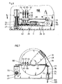
- the writing pens 34, 43, 44 are slidably mounted on a slide part 65 and are biased by springs 39 onto the diagram disk 31.
- the tips of the writing pens 34, 43, 44 must be lifted off the diagram disk 31 in order to avoid undesired recording tracks on the diagram disk.
- a relatively elongated, eccentric cam 67 is mounted on a shaft 66 mounted in the housing 1 Shaft 66 by means of protrusions 68 (FIG. 7) protruding from the pens lifts the pens from the chart disc 31, so that the chart disc 31 together with the plate 28 can now be moved out of the chamber 47 without the pens providing undesired traces of writing will.
- the shaft 66 and thus the cam 67 can be rotated in various ways for the purpose of lifting the pens.
- the twist could be derived from the pivoting or sliding movement of the plate 28.
- the shaft 66 can be adjusted simultaneously with the drive of this device by the necessary angular range in order to lift the pens off the diagram disk.
- the lifting movement of the pens is derived from the lock 102 with the associated key 103.
- the lock 102 serves to lock a wall part connected to the plate 28 which, when the chamber 47 is closed, can lie approximately in the plane of the front wall of the housing 1 formed by the disk 2.
- a coupling part 74 which is fixedly connected to a rotatable lock part 73, positively engages in a corresponding slot 75 on the end face of a rotatably mounted shaft 76 as soon as the wall part mentioned is closed.
- the shaft 76 can thus be rotated by a rotary movement of the key 103.
- the shaft 76 carries a bevel gear 77 which meshes with a bevel gear 78 seated on the shaft 66.
Description
Die Erfindung betrifft einen Fahrtschreiber für Kraftfahrzeuge nach dem Oberbegriff des Patentanspruchs 1.The invention relates to a tachograph for motor vehicles according to the preamble of
Die bekannten Fahrtschreiber dieser Art (FR-A-2 264 332) haben ein im wesentlichen zylindrisches Gehäuse, das aus zwei Gehäuseteilen besteht, nämlich einem Hauptgehäuse und einem Deckelgehäuse, wobei das Deckelgehäuse klappbar am Hauptgehäuse angeordnet ist und an seiner freien Stirnseite Anzeigeeinrichtungen mit einem Hauptzifferblatt für die sowohl im Hauptgehäuse als auch im Deckelgehäuse untergebrachten Meßinstrumente aufweist. Insbesondere enthält das Deckelgehäuse die Zeituhr und den von dieser angetriebenen Diagrammscheibenträger. Zum Auswechseln einer Diagrammscheibe muß das Deckelgehäuse vom Hauptgehäuse abgeklappt werden, wobei der eigentliche Auswechselvorgang wegen des geringen, zur Verfügung stehenden Raumes zwischen Haupt-und Deckelgehäuse meist nur mit Schwierigkeiten ausgeführt werden kann. Da die im Deckelgehäuse angeordneten Anzeigeeinrichtungen, beispielsweise ein Tachometerzeiger und der Wegstreckenzähler, vom ortsfesten Hauptgehäuse aus angetrieben werden, sind flexible Antriebsverbindungen erforderlich, die in ihre Herstellung aufwendig und störanfällig sind. Schließlich läßt das klappbare Deckelgehäuse mit seinem Hauptzifferblatt praktisch keinen Spielraum für die Gestaltung einer Kraftfahrzeug-Armaturentafel, da wesentliche Anzeigeeinrichtungen bereits an der Stirnseite des klappbaren, zylindrischen Deckelgehäuses vorgesehen sind.The known tachographs of this type (FR-A-2 264 332) have a substantially cylindrical housing which consists of two housing parts, namely a main housing and a cover housing, the cover housing being arranged in a foldable manner on the main housing and on its free end face display devices with a Main dial for the measuring instruments housed both in the main housing and in the cover housing. In particular, the cover housing contains the timer and the diagram disk carrier driven by it. To replace a diagram disc, the cover housing must be folded down from the main housing, and the actual replacement process can usually only be carried out with difficulty because of the small space available between the main and cover housing. Since the display devices arranged in the cover housing, for example a tachometer pointer and the odometer, are driven from the stationary main housing, flexible drive connections are required which are complex to manufacture and prone to failure. Finally, the hinged lid housing with its main dial leaves practically no scope for the design of a motor vehicle dashboard, since essential display devices are already provided on the front side of the hinged, cylindrical lid housing.
Aus der US-A-3 434 152 ist ein Fahrtschreiber für Kraftfahrzeuge bekannt, bei dem der Diagrammscheibenträger relativ zum Fahrtschreibergehäuse gleitverschieblich und fest mit einer Zeituhr verbunden ist, die also zusammen mit dem Diagrammscheibenträger hin- und herverschoben werden muß. Dies ist nachteilig, weil durch das Mitbewegen der Uhr deren Uhrwerk beschädigt oder in seiner Ganggenauigkeit beeinträchtigt werden könnte. Außerdem steht bei einer Anordnung der Uhr am beweglichen Diagrammscheibenträger nur wenig Platz zur Verfügung, so daß die Uhr klein ausgebildet werden muß, was die Ablesung der Uhr erschwert.From US-A-3 434 152 a tachograph for motor vehicles is known in which the chart carrier is slidably and fixedly connected to a timer clock relative to the tachograph housing, so that it has to be pushed back and forth together with the chart carrier. This is disadvantageous because the movement of the watch could damage its clockwork or impair its accuracy. In addition, there is little space available when the watch is arranged on the movable chart support, so that the watch must be made small, which makes reading the watch more difficult.
Es ist Aufgabe der Erfindung, unter Behebung der geschilderten Nachteile einen gattungsgemäßen Fahrtschreiber so zu gestalten, daß ein klappbares Deckelgehäuse entfällt, die Diagrammscheiben einfach und sicher eingelegt werden können, und eine vielfältige Ausgestaltung der Anzeigeeinrichtungen und damit der Armaturentafel des Kraftfahrzeuges möglich wird, sowie bei ortsfest gehaltener Zeituhr einen ständigen, zeitgenauen Antrieb des Diagrammscheibenträgers auch dann sicherzustellen, wenn dieser zum Diagrammscheibenwechsel aus dem Fahrtschreibergehäuse herausbewegt ist.It is an object of the invention, while eliminating the disadvantages described, to design a generic tachograph in such a way that a hinged cover housing is eliminated, the diagram disks can be inserted easily and securely, and a diverse design of the display devices and thus the dashboard of the motor vehicle is possible, as well as To keep the time clock stationary, ensure that the chart disc holder is always driven in a timely manner, even if it is moved out of the tachograph housing to change the chart disc.
Die Aufgabe wird erfindungsgemäß durch die kennzeichnenden Merkmale des Patentanspruchs 1 gelöst.The object is achieved by the characterizing features of
Die nachstehende Beschreibung bevorzugter Ausführungsformen der Erfindung dient im Zusammenhang mit beiliegender Zeichnung der weiteren Erläuterung. Es zeigen:
Figur 1- eine schematische, teilweise aufgebrochene Draufsicht eines Fahrtschreibers;
Figur 2- eine Schnittansicht entlang der Linie 2-2 in
Figur 1; Figur 3- eine schematische, teilweise aufgebrochene Draufsicht einer weiteren Ausführungsform eines Fahrtschreibers;
Figur 4- eine vergrößerte Schnittansicht entlang der Linie 4-4 in
Figur 3; Figur 5- eine Schnittansicht entlang der Linie 5-5 in
Figur 3; Figur 6- eine Ansicht einer anderen Ausführungsform eines Fahrtschreibers mit anhebbaren Schreibstiften und
Figur 7- eine schematische Schnittansicht entlang der Linie 7-7 in
Figur 6.
- Figure 1
- a schematic, partially broken plan view of a tachograph;
- Figure 2
- a sectional view taken along line 2-2 in Figure 1;
- Figure 3
- a schematic, partially broken plan view of a further embodiment of a tachograph;
- Figure 4
- an enlarged sectional view taken along line 4-4 in Figure 3;
- Figure 5
- a sectional view taken along line 5-5 in Figure 3;
- Figure 6
- a view of another embodiment of a tachograph with lifting pens and
- Figure 7
- is a schematic sectional view taken along line 7-7 in Figure 6.
Der in Figur 1 und 2 dargestellte Fahrtschreiber weist ein im wesentlichen quaderförmiges Gehäuse 1 auf, dessen Querschnittsform aus Figur 2 ersichtlich ist. Das Gehäuse 1 ist an seiner Vorderseite von einer durchsichtigen Scheibe 2 aus Glas oder Kunststoff abgedeckt. Dahinter befindet sich ein Zifferblatt 3 mit mehreren Skalen, über welche Zeiger spielen.The tachograph shown in Figures 1 and 2 has an essentially
Das Zifferblatt umfaßt eine Tachometerskale 5, der ein von einem Geschwindigkeitsmesser 6 (Figur 2) angetriebener Zeiger 7 zugeordnet ist. Weiterhin umfaßt das Zifferblatt 3 Symbole 8 (Figur 1), die jeweils einem Zeitgruppenschalter 11 bzw. 12 zugeordnet sind. An diesen Schaltern können zwei Fahrer eines Kraftfahrzeuges in herkömmlicher Weise abwechselnd ihre Arbeits-, Ruhezeiten und dergleichen einstellen. Schließlich umfaßt das Zifferblatt 3 Schlitze 13, 14, an denen in bekannter Weise die anzeigenden Ziffern eines Wegstreckenzählers 15 bzw. eines Tageskilometerzählers 16 sichtbar werden. Die Zähler liegen hinter dem Zifferblatt 3 und sind mit dem einstückigen, unteilbaren Gehäuse 1 ständig fest verbunden.The dial comprises a
Das Zifferblatt 3 umfaßt ferner eine Drehzahlskale 17 mit Zeiger 18 eines ebenfalls im Gehäuse 1 untergebrachten (nicht dargestellten) Drehzahlmessers.The
Über einem seitlich zur Tachometerskale 5 versetzten Zifferblatt 21 einer Zeituhr mit Uhrwerk 24 sind Uhrzeiger 22, 23 verdrehbar. Auch das Uhrwerk 24 der Zeituhr ist im Gehäuse 1 ortsfest gelagert.
Im Gehäuse 1 ist weiterhin um eine Achse 27 schwenkbar eine Platte 28 gelagert, auf welcher ein vom Uhrwerk 24 drehend angetriebener Diagrammscheibenträger 29 angeordnet ist. Der Diagrammscheibenträger 29 dient in an sich bekannter Weise der Aufnahme einer oder mehrerer Diagrammscheiben, von denen auf der Zeichnung lediglich eine Diagrammscheibe 31 dargestellt ist. Auf den Diagrammscheiben werden in ebenfalls herkömmlicher Weise im Betriebszustand des Fahrtschreibers die von den Instrumenten im Gehäuse 1 gelieferten Meßwerte aufgezeichnet. Die Instrumente umfassen zu diesem Zweck Registriereinrichtungen, die ihrerseits in bekannter Weise mit Schreibstiften verbunden sind, welche die Oberfläche der Diagrammscheibe(n) beschriften. Mit derartigen Registriereinrichtungen sind insbesondere auch die Zeitgruppenschalter 11, 12 versehen. Ein in Figur 2 sichtbares Ritzel 42 wird über den Zeitgruppenschalter 11 verdreht. Das Ritzel 42 kämmt mit einer Zahnstange 41, die starr mit dem Gehäuse 40 eines Schreibstiftes 34 verbunden ist. Das Schreibstiftgehäuse 40 ist auf einer von zwei Stangen 36, 37 gebildeten Führung quer über die Ebene der Diagrammscheibe 31 verschieblich. Somit kann bei Verdrehung des Zeitgruppenschalters 11 der Schreibstift 34 so eingestellt werden, daß er auf die Diagrammscheibe 31 eine Kreisspur bestimmten Radius konzentrisch zur Drehachse 30 der Diagrammscheibe 31 aufzeichnet. Weitere Schreibstifte 43, 44 sind dem Geschwindigkeitsmesser 6 und dem Wegstreckenzähler 15 zugeordnet und mit diesen Bauteilen über entsprechende Brückenglieder antriebsmäßig verbunden. Durch die Brückenglieder, beispielsweise Zahnstangen entsprechend der Zahnstange 41, wird die räumliche Entfernung zwischen den Meßinstrumenten und der Diagrammscheibe 31 überbrückt, so daß dort die von den Instrumenten angezeigten Meßwerte richtig aufgezeichnet werden.In the
In Figur 1 ist der lineare Schreibbereich, innerhalb dessen sich die Schreibstifte 34, 43 und 44 bewegen, durch einen Doppelpfeil S angedeutet.In Figure 1, the linear writing area, within which the
Durch Verschwenken der Platte 28 kann der Diagrammscheibenträger 29 im Außer-Betriebszustand des Fahrtschreibers nach oben aus dem Gehäuse herausgeschwenkt werden, wo in bequemer Weise Diagrammscheiben 31 ausgewechselt werden können.By pivoting the
Im Betriebszustand liegt der Diagrammscheibenträger 29 mit der oder den an ihm befestigten Diagrammscheiben in einer Kammer 47 des Gehäuses 1. Bei der dargestellten Ausführungsform verläuft die Schwenkachse 27 der Platte 28 parallel zur Achse des Tachometerzeigers 7, die Platte 28 wird also in einer Ebene verschwenkt, die im wesentlichen zum Zifferblatt 3 an der Vorderseite des Gehäuses 1 parallel ist. Gewöhnlich ist die Scheibe 2 und mit ihr das Gehäuse 1 zur Horizontalen schräg geneigt, so daß der Fahrer eines Kraftfahrzeuges das Zifferblatt 3 bequem überschauen kann. In diesem Falle kann die Platte 28 in einer entsprechend schräg verlaufenden Ebene oben aus dem Gehäuse 1 herausgeschwenkt werden. Die Schwenkachse 27 muß nicht parallel zur Drehachse des Tachometerzeigers 7 verlaufen. In diesem Falle kann auch bei schräg angeordnetem Gehäuse erreicht werden, daß die Platte 28 und der Diagrammscheibenträger 29 in einer im wesentlichen vertikalen Ebene beweglich sind.In the operating state, the
Bei der dargestellten Ausführungsform liegt die den Diagrammscheibenträger 29 aufnehmende Kammer 47 etwa in der Mitte zwischen den Skalen 5, 17 des Zifferblattes 3 und hinter den Anzeigeeinrichtungen der diesen Zeigern zugeordneten Meßinstrumenten. Im Betriebszustand ist daher der Diagrammscheibenträger 29 gegenüber der Tachometerskale 5 und der Drehzahlskale 17 seitlich versetzt. Dieser seitliche Versatz ist nicht unbedingt erforderlich. Bei einer anderen Ausführungsform der Erfindung kann die Drehachse 27 auch so angeordnet werden, daß der Diagrammscheibenträger 29 im Betriebszustand des Fahrtschreibers ohne seitlichen Versatz hinter der Anzeigeeinrichtung 6 des Tachometers liegt, beispielsweise so, daß die Drehachse 30 des Diagrammscheibenträgers 29 im wesentlichen koaxial mit der Zeigerwelle des Zeigers 7 verläuft. Auf diese Weise erhält man eine besonders kompakte, platzsparende Ausführungsform, wobei durch das oben erfolgende Herausschwenken des Diagrammscheibenträgers 29 dennoch die Diagrammscheiben 31 leicht zugänglich gemacht werden können, ohne das Gehäuse durch Aufklappen trennen zu müssen. Mit dem Herausbewegen des Diagrammscheibenträgers 29 aus dem Gehäuse 1 müssen auch keinerlei Meßinstrumente oder Teile dieser Instrumente sowie Registriereinrichtungen mit bewegt werden, wie dies bisher bei den klappbaren Deckelgehäusen bekannter Fahrtschreiber der Fall war.In the embodiment shown, the
Die Bewegung des Diagrammscheibenträgers erfolgt in einer Ebene, welche zur Ebene der Diagrammscheibe im wesentlichen parallel verläuft.The movement of the diagram disk carrier takes place in a plane which runs essentially parallel to the plane of the diagram disk.
Der Diagrammscheibenträger 29 wird ausgehend vom Uhrwerk 24 der Zeituhr über eine Welle 50 angetrieben. Auf der Schwenkachse 27 der den Diagrammscheibenträger 29 tragenden Platte 28 ist drehbar eine Buchse 55 angeordnet, die an ihrem in Figur 2 rechts gelegenen Ende ein Kegelzahnrad 56 aufweist. Dieses Kegelzahnrad 56 kämmt mit dem Kegelzahnrad 57 (Figur 1), welches über die Welle 50 zum Uhrwerk 24 zeitgenau angetrieben ist. Die Buchse weist ferner an ihrem in Figur 2 links liegenden Ende ein Zahnrad 61 (Figur 2) auf, welches mit einem auf der Platte 28 gelagerten Zahnrad 62 (Figur 1) kämmt. Ausgehend von diesem Zahnrad 62 wird über ein weiteres Zahnrad 63 der damit drehfest verbundenen Diagrammscheibenträger 29 zeitgenau angetrieben. Aufgrund dieser Getriebeverbindung kann die Platte 28 um die Achse 27 verschwenkt werden, ohne den Eingriff mit dem Uhrwerk 24 und den zeitgenauen Antrieb zu beeinträchtigen. Beim Zurückverschwenken der Platte 28 in die Kammer 47 wird im übrigen ein Zahnspiel dieses Getriebezuges zwischen Zeituhr und Diagrammscheibenträger beseitigt.The
Wie dargestellt, ist mit der Platte 28, von dieser senkrecht abstehend, ein Deckel 101 verbunden, der zusammen mit der Platte 28 verschwenkt wird und im Betriebszustand des Fahrtschreibers die den Diagrammscheibenträger 29 aufnehmende Kammer 47 dicht verschließt. Am Deckel 101 ist ein Schloß 102 mit abziehbarem Schlüssel 103 angeordnet. Das Schloß 102 ist in bekannter Weise als Rastschloß so ausgebildet, daß es beim Verschwenken des Deckels 101 in Schließstellung ohne Verdrehung des Schlüssels 103 einschnappt und den Deckel verschließt. Der Schlüssel 103 muß nur zum Öffnen in das Schloß 102 eingeführt und verdreht werden.As shown, a
Der Platte 28 kann im übrigen in an sich bekannter und daher nicht eigens dargestellter Weise eine zweite Rasteinrichtung zugeordnet werden, welche die Platte im Außer-Betriebszustand des Fahrtschreibers in ihrer nach oben aus dem Gehäuse heraus verschwenkten Position feststellt, so daß Diagrammscheiben 31 bequem ausgewechselt werden können, ohne die Platte 28 festhalten zu müssen.The
Der Deckel 101 deckt beim Verschließen nicht nur die den Diagrammscheibenträger 29 und die Diagrammscheiben 31 aufnehmende Kammer 47 des Gehäuses 1 ab, sondern zusätzlich noch weitere Funktionsteile des Fahrtschreibers. Zu diesen Funktionsteilen gehört insbesondere ein Einstellknopf 104 für die Zeituhr. Der Knopf 104, der in Figur 1 schematisch angedeutet ist, ist an der der Diagrammscheibe 31 abgekehrten Seite der Platte 28 gelagert. Er ist, wie ebenfalls aus Figur 1 ersichtlich, Über Getrieberäder an das Getrieberad 62 angeschlossen, so daß beim Verdrehen des Knopfes 104 die Zeituhr eingestellt werden kann. Beim Verschließen des Deckels 101 ist der Stellknopf 104 nicht mehr zugänglich.When closing, the
In der Kammer 47 sind als weitere Funktionsteile des Fahrtschreibers ferner ein Kodierschalter 105 und eine Steckbuchse 106 an einem Träger 107 fest angeordnet (wie in Figur 1 schematisch angedeutet). An zwei Fahnen 108, 109 der Steckbuchse 106 können elektrische Leitungen angeordnet werden. Wie an sich bekannt, kann am entsprechend eingestellten Kodierschalter 105, der gewöhnlich zusätzlich plombiert ist, an der Steckbuchse 106 die Richtigkeit einer Messung überprüft oder eine entsprechende Eichung durchgeführt werden. Bei geöffnetem Deckel 101 ist die Steckbuchse 106 ohne Behinderung zugänglich. Bei geschlossenem Deckel 101 sind auch die Steckbuchse 106 und der Kodierschalter 107 unzugänglich abgedeckt.In the
Die Figuren 3 bis 5 zeigen eine gegenüber Figur 1 und 2 abgewandelte Ausführungsform eines Fahrtschreibers. In den Figuren 3 bis 5 sind einander entsprechende Teile mit den gleichen Bezugszeichen wie in Figur 1 und 2 bezeichnet.FIGS. 3 to 5 show an embodiment of a tachograph modified from FIGS. 1 and 2. In the Figures 3 to 5 are corresponding parts with the same reference numerals as in Figures 1 and 2.
Der wesentliche Unterschied zwischen den beiden Ausführungsformen besteht darin, daß die den Diagrammscheibenträger 29 und die Diagrammscheibe(n) tragende Platte 28 mit dem Deckel 101 nicht schwenkbar, sondern gleitverschieblich nach oben aus dem Gehäuse 1 heraus bewegbar ist. Hierzu ist die Platte 28 (vgl. Figur 4) beidseits in Gleitführungen 111 verschieblich gelagert, deren Mittellinien in Figur 3 strichpunktiert angegeben und ebenfalls mit den Bezugszeichen 111 bezeichnet sind. Der Schreibbereich S ist bei der Ausführungsform gemäß Figur 3 bis 5 gegenüber dem Schreibbereich S der Ausführungsform nach Figur 1 und 2 um 90° verdreht und verläuft parallel zur Schieberichtung der Platte 28 (Figur 3). Im übrigen gilt alles, was im Zusammenhang mit der Ausführungsform nach Figur 1 und 2 ausgeführt wurde, auch für die Ausführungsform nach Figur 3 bis 5. Insbesondere kann der Diagrammscheibenträger 29 im Betriebszustand des Fahrtschreibers auch ohne seitlichen Versatz direkt hinter der Tachometerskale 5 liegen.The essential difference between the two embodiments is that the
Die Figur 5 zeigt mit ausgezogenen Linien den Diagrammscheibenträger 28 in seiner nach oben aus dem Fahrtschreibergehäuse 1 herausgeschobenen Position. Die Betriebsstellung mit eingeschobenem Diagrammscheibenträger 29 ist in Figur 5 gestrichelt dargestellt.FIG. 5 shows the
Um bei dem Herausschieben des Diagrammscheibenträgers 29 seine getriebemäßige Verbindung mit dem Uhrwerk 24 nicht zu unterbrechen, ist folgende Anordnung getroffen:
Ein den Diagrammscheibenträger 29 antreibendes Kegelrad 112 ist drehfest mit einer Stange 113 verbunden. Die Stange 113 ist in einem parallel zu ihr verlaufenden Rohr 114 gleitverschieblich (teleskopierend) geführt. Von der Stange 113 steht ein Stift 115 seitlich ab, der sich in einen axial verlaufenden Schlitz 119 im Rohr 114 hinein erstreckt. Auf diese Weise sind Stange 113 und Rohr 114 drehfest, jedoch gleitverschieblich miteinander verbunden. Bei einem Herausziehen der Platte 28 aus dem Gehäuse 1 gleitet die Stange 113 aus dem Rohr 114 nach oben, ohne ihre drehschlüssige Verbindung mit diesem Rohr zu verlieren. Das Rohr 114 weist an seiner in Figur 5 unten gelegenen Seite ein Kegelrad 116 auf, das mit dem Kegelrad 117 kämmt. Das Kegelrad 117 wird über eine Welle 118 vom Uhrwerk 24 angetrieben. Somit steht der Diagrammscheibenträger 29 ständig in antriebsmäßiger Verbindung mit dem Uhrwerk 24, auch wenn er im Außer-Betriebszustand des Fahrtschreibers aus dessen Gehäuse 1 herausgeschoben ist.In order not to interrupt its transmission connection to the clockwork 24 when the
A
Wie in Figur 6 bei einer etwas abgewandelten Ausführungsform eines Fahrtenschreibers dargestellt, sind die Schreibstifte 34, 43, 44 verschieblich an einem Schlittenteil 65 gelagert und werden von Federn 39 auf die Diagrammscheibe 31 vorgespannt. Wenn die den Diagrammscheibenträger 29 halternde Platte 28 um die Achse 27 verschwenkt wird, müssen die Schreibstifte 34, 43, 44 mit ihren Spitzen von der Diagrammscheibe 31 abgehoben werden, um unerwünschte Aufzeichnungsspuren auf der Diagrammscheibe zu vermeiden. Zu diesem Zwecke ist an einer im Gehäuse 1 gelagerten Welle 66 ein verhältnismäßig langgestreckter, exzentrischer Nocken 67 gelagert, der beim Verdrehen der Welle 66 mittels von den Schreibstiften abstehender Vorsprünge 68 (Figur 7) die Schreibstifte von der Diagrammscheibe 31 abhebt, so daß nunmehr die Diagrammscheibe 31 zusammen mit der Platte 28 aus der Kammer 47 herausbewegt werden kann, ohne hierbei von den Schreibstiften mit unerwünschten Schreibspuren versehen zu werden.As shown in FIG. 6 in a somewhat modified embodiment of a tachograph, the writing pens 34, 43, 44 are slidably mounted on a
Die Welle 66 und damit der Nocken 67 kann in verschiedener Weise zum Zwecke der Anhebung der Schreibstifte verdreht werden. Beispielsweise könnte die Verdrehung von der Schwenkbewegung oder Verschiebebewegung der Platte 28 abgeleitet sein. Falls der Fahrtschreiber eine automatische Einzugs- und Auswerfeinrichtung für die Diagrammscheiben aufweist, kann gleichzeitig mit dem Antrieb dieser Einrichtung die Welle 66 um den notwendigen Winkelbereich verstellt werden, um die Schreibstifte von der Diagrammscheibe abzuheben. Bei der in Figur 6 und 7 dargestellten Ausführungsform wird die Abhebebewegung der Schreibstifte von dem Schloß 102 mit zugehörigem Schlüssel 103 abgeleitet. Das Schloß 102 dient der Verriegelung eines mit der Platte 28 verbundenen Wandteils, welches bei geschlossener Kammer 47 etwa in der Ebene der von der Scheibe 2 gebildeten Vorderwand des Gehäuses 1 liegen kann. Wie schematisch dargestellt, greift ein mit einem drehbaren Schloßteil 73 fest verbundener Kupplungsteil 74 formschlüssig in einen korrespondierenden Schlitz 75 an der Stirnseite einer drehbar gelagerten Welle 76 ein, sobald das erwähnte Wandteil geschlossen ist. Somit kann durch eine Drehbewegung des Schlüssels 103 die Welle 76 verdreht werden. Die Welle 76 trägt ein Kegelzahnrad 77, das mit einem auf der Welle 66 sitzenden Kegelrad 78 kämmt. Beim Verdrehen des Schlüssels 103 können somit durch die dadurch bedingte Drehung der Welle 66 um den erforderlichen Winkelbereich die Schreibstifte 34, 43, 44 von der Diagrammscheibe 31 abgehoben und wieder in Schreibstellung zurückgebracht werden.The
Es besteht häufig die Vorschrift, einen Fahrtschreiber zur Verhinderung unerlaubter Manipulationen zu plombieren. Auch dies ist bei dem hier vorgeschlagenen Fahrtschreiber in einfacher Weise möglich, beispielsweise dadurch, daß man die Anzeige- und Registriereinrichtungen gemeinsam in einem plombierbaren Gehäuseblock unterbringt und diesen Block in plombierter Form in das Gehäuse 1 einsetzt.There is often a requirement to seal a tachograph to prevent unauthorized manipulation. This is also possible in a simple manner in the tachograph proposed here, for example by accommodating the display and registration devices together in a sealable housing block and inserting this block into the
Claims (20)
- Tachograph for motor vehicles, having a housing (1) with measuring instruments arranged in the housing, including a speedometer (6), odometer (15, 16) and clock (24), the measuring instruments comprising recording devices and display devices, having styluses (34, 43, 44) connected to the recording devices, having at least one main dial, which is provided on the front side of the housing, which is assigned to the display devices and comprises the scales of the speedometer, the odometer and time groups (8), and having a speed-time chart carrier (29), rotatably driven by the clock, for accommodating at least one speed-time chart (31) on which the styluses record the measured values displayed by the measuring instruments, the recording devices being connected to the display devices in a permanently undetachable fashion, the speed-time chart carrier being arranged in a separate chamber (47) of the housing which is spatially offset from the main dial, the styluses likewise being arranged over the speed-time chart offset with respect to the main dial and being connected to the recording devices, and the speed-time chart carrier being movable relative to the recording and display devices, which are fixed in the housing, of the measuring instruments for the purpose of replacing the speed-time chart, characterised in that the clock (24) is arranged fixed in the housing (1) relative to the movable speed-time chart carrier (29) and is permanently connected via a gear train (54 to 61) to the movable speed-time chart carrier, and in that for the purpose of replacing the speed-time chart the speed-time chart carrier (29) can be moved in a plane which is essentially parallel to the main dial (5) and to the speed-time chart held in the speed-time chart carrier.
- Tachograph according to Claim 1, characterised in that the styluses (34, 43, 44) can be raised relative to the plane of the speed-time chart (31) for the purpose of replacing the speed-time chart.
- Tachograph according to Claim 2, characterised in that a movement of the speed-time chart carrier (29) relative to the recording and display devices automatically triggers the raising of the styluses (34, 43, 44).
- Tachograph according to Claim 2, characterised in that the styluses (34, 43, 44) can be raised by operating a lock (102) which locks the chamber.
- Tachograph according to Claim 1, characterised in that the speed-time chart carrier (29) is arranged on a plate (28) which can be slidably displaced relative to the housing (1).
- Tachograph according to Claim 1, characterised in that the speed-time chart carrier (29) is arranged on a plate (28), which is mounted rotatably on the housing (1) and can be swivelled into and out of the chamber (47).
- Tachograph according to one of the preceding claims, characterised in that the display and recording devices are combined in a sealable housing block and this block can be inserted into the housing (1).
- Tachograph according to Claim 1, characterised in that the chamber (47) and the speed-time chart carrier (29) are arranged spatially behind the speedometer (6) and its pointer (7) in the operating state of the tachograph, and the speed-time chart carrier (29) can be moved upwards out of the housing (1).
- Tachograph according to Claim 8, characterised in that the speed-time chart carrier (29) is mounted in the housing (1) rotatably about an axis (27) and can be swivelled upwards out of the housing (1), with the speedometer (6) remaining fixed.
- Tachograph according to Claim 8, characterised in that the speed-time chart carrier (29) is mounted in the housing (1) in a manner capable of displacement by sliding and can be slid upwards out of the housing with the speedometer (6) remaining fixed.
- Tachograph according to Claim 8, characterised in that the speed-time chart carrier (29) can be moved in an essentially vertical plane.
- Tachograph according to Claim 8, characterised in that in the operating state of the tachograph the axis (27) of rotation of the speed-time chart carrier (29) extends essentially parallel to the shaft of the pointer (7) of the speedometer (6).
- Tachograph according to Claim 8, characterised in that the chamber (47) accommodating the speed-time chart carrier (29) can be closed by a sealable cover (101).
- Tachograph according to Claim 13, characterised in that the cover (101) of the [sic] is arranged on a plate (28) supporting the speed-time chart carrier (29).
- Tachograph according to Claim 13, characterised in that the cover (101) simultaneously covers further functional parts (105, 106) of the tachograph, in particular a setting knob (104) for the clock (24).
- Tachograph according to Claim 15, characterised in that the setting knob (104) for the clock (24) is arranged on the plate (28) holding the speed-time chart carrier (29).
- Tachograph according to Claim 15, characterised in that the further functional parts comprise a coding switch (105) and a socket-contact (106).
- Tachograph according to Claim 9, characterised in that a gear train (50, 57, 62, 63) permanently connecting the clock (24) to the swivelable speed-time chart carrier (29) includes a gear wheel (56) coaxial with the swivel axis (27).
- Tachograph according to Claim 10, characterised in that a gear train (112, 116, 117) permanently connecting the clock (24) to the slidably displaceable speed-time chart carrier (29) includes a rotationally fixed telescopic connection (113, 114, 115).
- Tachograph according to Claim 8, characterised in that the speedometer (6) and the odometer (15, 16) with the main dial (5), and the pointers (7, 18, 22, 23) as well as the recording devices with the styluses (34, 43, 44) are accommodated by a common, fixed, indivisible housing (1).
Applications Claiming Priority (4)
| Application Number | Priority Date | Filing Date | Title |
|---|---|---|---|
| DE19863618109 DE3618109A1 (en) | 1986-05-30 | 1986-05-30 | Tachograph (recording speedometer) for motor vehicles |
| DE3618109 | 1986-05-30 | ||
| DE3626892 | 1986-08-08 | ||
| DE19863626892 DE3626892A1 (en) | 1986-08-08 | 1986-08-08 | Tachograph for motor vehicles |
Publications (3)
| Publication Number | Publication Date |
|---|---|
| EP0247550A2 EP0247550A2 (en) | 1987-12-02 |
| EP0247550A3 EP0247550A3 (en) | 1988-05-04 |
| EP0247550B1 true EP0247550B1 (en) | 1992-09-16 |
Family
ID=25844186
Family Applications (1)
| Application Number | Title | Priority Date | Filing Date |
|---|---|---|---|
| EP87107539A Expired - Lifetime EP0247550B1 (en) | 1986-05-30 | 1987-05-23 | Tachograph for motor vehicles |
Country Status (3)
| Country | Link |
|---|---|
| US (1) | US4862191A (en) |
| EP (1) | EP0247550B1 (en) |
| ES (1) | ES2034986T3 (en) |
Families Citing this family (6)
| Publication number | Priority date | Publication date | Assignee | Title |
|---|---|---|---|---|
| DE8805789U1 (en) * | 1988-05-02 | 1988-07-14 | Mannesmann Kienzle Gmbh, 7730 Villingen-Schwenningen, De | |
| DE3838280A1 (en) * | 1988-11-11 | 1990-05-17 | Mannesmann Kienzle Gmbh | TACHOGRAPH WITH TIME-DRIVEN DRIVES FOR DIAGRAM DISKS TO BE USED AS RECORDING CARRIERS |
| DE9317101U1 (en) * | 1993-11-09 | 1994-03-03 | Mannesmann Kienzle Gmbh | Motor vehicle with a tachograph |
| CH689987A5 (en) * | 1994-04-19 | 2000-02-29 | Smh Management Services Ag | compact display for the reading of several measures and compact panel comprising such a device. |
| DE29610675U1 (en) * | 1996-06-18 | 1996-08-29 | Vdo Schindling | Tachograph with a drive for the time-dependent drive of diagram disks serving as recording media |
| DE20004685U1 (en) * | 2000-03-14 | 2000-06-29 | Mannesmann Vdo Ag | Arrangement for clamping a bundle of diagram disks on a recording driven by the tachograph's registration drive in a time-synchronized manner |
Family Cites Families (15)
| Publication number | Priority date | Publication date | Assignee | Title |
|---|---|---|---|---|
| US1514524A (en) * | 1922-10-18 | 1924-11-04 | Taylor Instrument Co | Recording instrument |
| US1619241A (en) * | 1926-06-21 | 1927-03-01 | Republic Flow Meters Co | Pen lifter for recording instruments |
| US1910361A (en) * | 1930-08-08 | 1933-05-23 | Permutit Co | Chart recording meter |
| US2152333A (en) * | 1937-06-18 | 1939-03-28 | Republic Flow Meters Co | Recording instrument |
| US2204046A (en) * | 1939-04-28 | 1940-06-11 | James H Melville | Pen lifting attachment for recording meters |
| US2873163A (en) * | 1954-06-16 | 1959-02-10 | Bailey Meter Co | Pen lifting and chart support for recording meters |
| BE555407A (en) * | 1956-03-02 | |||
| US3281856A (en) * | 1961-04-10 | 1966-10-25 | Litton Systems Inc | Microwave recording upon a deformable medium |
| DE1548685B1 (en) * | 1966-01-13 | 1970-07-30 | Kienzle Apparate Gmbh | Tachographs for motor vehicles |
| DE2237087B2 (en) * | 1972-07-28 | 1980-03-13 | Kienzle Apparate Gmbh, 7730 Villingen-Schwenningen | Tachograph |
| DE2411515C2 (en) * | 1974-03-11 | 1985-03-07 | Moto Meter Ag, 7250 Leonberg | Tachograph with measuring and writing mechanisms |
| LU72703A1 (en) * | 1974-07-13 | 1975-10-08 | ||
| DE2917329A1 (en) * | 1979-04-28 | 1980-11-06 | Kienzle Apparate Gmbh | REGISTRATION DEVICE |
| DE3046118A1 (en) * | 1980-12-06 | 1982-07-22 | Kienzle Apparate Gmbh, 7730 Villingen-Schwenningen | TRAINING OF A HOUSING, ESP. FOR TACHOGRAPHERS, AND A SWIVELING LID ARRANGED TO THE HOUSING |
| DE3142677A1 (en) * | 1981-10-28 | 1983-05-05 | Kienzle Apparate Gmbh, 7730 Villingen-Schwenningen | Tachograph |
-
1987
- 1987-05-23 ES ES198787107539T patent/ES2034986T3/en not_active Expired - Lifetime
- 1987-05-23 EP EP87107539A patent/EP0247550B1/en not_active Expired - Lifetime
-
1988
- 1988-08-19 US US07/235,819 patent/US4862191A/en not_active Expired - Fee Related
Also Published As
| Publication number | Publication date |
|---|---|
| ES2034986T3 (en) | 1993-04-16 |
| EP0247550A3 (en) | 1988-05-04 |
| US4862191A (en) | 1989-08-29 |
| EP0247550A2 (en) | 1987-12-02 |
Similar Documents
| Publication | Publication Date | Title |
|---|---|---|
| EP0012223B1 (en) | Tachograph | |
| EP0247550B1 (en) | Tachograph for motor vehicles | |
| DE2536346C3 (en) | Device for displaying maintenance work to be carried out on a vehicle | |
| EP0624856B1 (en) | Tachograph for motor vehicle | |
| DE1548685B1 (en) | Tachographs for motor vehicles | |
| DE7811664U1 (en) | DEVICE FOR DISPLAYING MEASURED VALUES | |
| DE2411515C2 (en) | Tachograph with measuring and writing mechanisms | |
| DE102016124958B4 (en) | Display device for a door closer with adjustable closing force and door closer | |
| DE1266036B (en) | Tachographs for motor vehicles | |
| DE3618109C2 (en) | ||
| DE1268889C2 (en) | Tachograph with an essentially cylindrical installation housing | |
| EP0800151B1 (en) | Drive connection for a tachograph registering device | |
| DE2336058C3 (en) | Device for precise setting and measuring of angles on drawing machines | |
| DE3626892A1 (en) | Tachograph for motor vehicles | |
| DE3730215C1 (en) | Tachographs for motor vehicles | |
| EP0306907B1 (en) | tachograph for motor vehicles | |
| EP0368219B1 (en) | Tachograph with time-dependently driven interaction means for diagram discs serving as record carriers | |
| DE1056401B (en) | Tachograph | |
| DE938339C (en) | Tachograph for vehicles driven by machine power | |
| DE3639625A1 (en) | Trip recorder | |
| DE2414231C2 (en) | Tachograph | |
| DE1955039C3 (en) | Tachograph | |
| DE2227726A1 (en) | Time-dependent recording device | |
| EP0255934A2 (en) | Tachograph for motor vehicles | |
| EP0184142B1 (en) | Sliding contact switch for a signalling device in a tachograph |
Legal Events
| Date | Code | Title | Description |
|---|---|---|---|
| PUAI | Public reference made under article 153(3) epc to a published international application that has entered the european phase |
Free format text: ORIGINAL CODE: 0009012 |
|
| AK | Designated contracting states |
Kind code of ref document: A2 Designated state(s): ES FR GB IT SE |
|
| PUAL | Search report despatched |
Free format text: ORIGINAL CODE: 0009013 |
|
| AK | Designated contracting states |
Kind code of ref document: A3 Designated state(s): ES FR GB IT SE |
|
| 17P | Request for examination filed |
Effective date: 19880810 |
|
| 17Q | First examination report despatched |
Effective date: 19900928 |
|
| GRAA | (expected) grant |
Free format text: ORIGINAL CODE: 0009210 |
|
| AK | Designated contracting states |
Kind code of ref document: B1 Designated state(s): ES FR GB IT SE |
|
| GBT | Gb: translation of ep patent filed (gb section 77(6)(a)/1977) | ||
| ET | Fr: translation filed | ||
| ITF | It: translation for a ep patent filed |
Owner name: STUDIO JAUMANN |
|
| REG | Reference to a national code |
Ref country code: ES Ref legal event code: FG2A Ref document number: 2034986 Country of ref document: ES Kind code of ref document: T3 |
|
| PLBI | Opposition filed |
Free format text: ORIGINAL CODE: 0009260 |
|
| 26 | Opposition filed |
Opponent name: MANNESMANN KIENZLE GMBH Effective date: 19930615 |
|
| PLBN | Opposition rejected |
Free format text: ORIGINAL CODE: 0009273 |
|
| STAA | Information on the status of an ep patent application or granted ep patent |
Free format text: STATUS: OPPOSITION REJECTED |
|
| 27O | Opposition rejected |
Effective date: 19940520 |
|
| EAL | Se: european patent in force in sweden |
Ref document number: 87107539.6 |
|
| PGFP | Annual fee paid to national office [announced via postgrant information from national office to epo] |
Ref country code: ES Payment date: 19960531 Year of fee payment: 10 |
|
| PGFP | Annual fee paid to national office [announced via postgrant information from national office to epo] |
Ref country code: GB Payment date: 19970506 Year of fee payment: 11 |
|
| PGFP | Annual fee paid to national office [announced via postgrant information from national office to epo] |
Ref country code: FR Payment date: 19970523 Year of fee payment: 11 |
|
| PG25 | Lapsed in a contracting state [announced via postgrant information from national office to epo] |
Ref country code: ES Free format text: LAPSE BECAUSE OF NON-PAYMENT OF DUE FEES Effective date: 19970524 |
|
| PGFP | Annual fee paid to national office [announced via postgrant information from national office to epo] |
Ref country code: SE Payment date: 19970526 Year of fee payment: 11 |
|
| PG25 | Lapsed in a contracting state [announced via postgrant information from national office to epo] |
Ref country code: GB Free format text: LAPSE BECAUSE OF NON-PAYMENT OF DUE FEES Effective date: 19980523 |
|
| PG25 | Lapsed in a contracting state [announced via postgrant information from national office to epo] |
Ref country code: SE Free format text: LAPSE BECAUSE OF NON-PAYMENT OF DUE FEES Effective date: 19980524 |
|
| PG25 | Lapsed in a contracting state [announced via postgrant information from national office to epo] |
Ref country code: FR Free format text: LAPSE BECAUSE OF NON-PAYMENT OF DUE FEES Effective date: 19980531 |
|
| GBPC | Gb: european patent ceased through non-payment of renewal fee |
Effective date: 19980523 |
|
| EUG | Se: european patent has lapsed |
Ref document number: 87107539.6 |
|
| REG | Reference to a national code |
Ref country code: FR Ref legal event code: ST |
|
| REG | Reference to a national code |
Ref country code: ES Ref legal event code: FD2A Effective date: 19990301 |
|
| PG25 | Lapsed in a contracting state [announced via postgrant information from national office to epo] |
Ref country code: IT Free format text: LAPSE BECAUSE OF NON-PAYMENT OF DUE FEES;WARNING: LAPSES OF ITALIAN PATENTS WITH EFFECTIVE DATE BEFORE 2007 MAY HAVE OCCURRED AT ANY TIME BEFORE 2007. THE CORRECT EFFECTIVE DATE MAY BE DIFFERENT FROM THE ONE RECORDED. Effective date: 20050523 |