EP0800151B1 - Drive connection for a tachograph registering device - Google Patents
Drive connection for a tachograph registering device Download PDFInfo
- Publication number
- EP0800151B1 EP0800151B1 EP97104665A EP97104665A EP0800151B1 EP 0800151 B1 EP0800151 B1 EP 0800151B1 EP 97104665 A EP97104665 A EP 97104665A EP 97104665 A EP97104665 A EP 97104665A EP 0800151 B1 EP0800151 B1 EP 0800151B1
- Authority
- EP
- European Patent Office
- Prior art keywords
- spacer plate
- recording
- carriage
- drive connection
- drawer
- Prior art date
- Legal status (The legal status is an assumption and is not a legal conclusion. Google has not performed a legal analysis and makes no representation as to the accuracy of the status listed.)
- Expired - Lifetime
Links
Images
Classifications
-
- G—PHYSICS
- G07—CHECKING-DEVICES
- G07C—TIME OR ATTENDANCE REGISTERS; REGISTERING OR INDICATING THE WORKING OF MACHINES; GENERATING RANDOM NUMBERS; VOTING OR LOTTERY APPARATUS; ARRANGEMENTS, SYSTEMS OR APPARATUS FOR CHECKING NOT PROVIDED FOR ELSEWHERE
- G07C5/00—Registering or indicating the working of vehicles
- G07C5/08—Registering or indicating performance data other than driving, working, idle, or waiting time, with or without registering driving, working, idle or waiting time
- G07C5/12—Registering or indicating performance data other than driving, working, idle, or waiting time, with or without registering driving, working, idle or waiting time in graphical form
-
- G—PHYSICS
- G01—MEASURING; TESTING
- G01P—MEASURING LINEAR OR ANGULAR SPEED, ACCELERATION, DECELERATION, OR SHOCK; INDICATING PRESENCE, ABSENCE, OR DIRECTION, OF MOVEMENT
- G01P1/00—Details of instruments
- G01P1/12—Recording devices
- G01P1/122—Speed recorders
- G01P1/125—Speed recorders with recording discs
Definitions
- the invention relates to a drive connection for a registration member in a tachograph with a flat installation housing, in which as Record carrier simultaneously two coaxially arranged and means a drawer between an insertion / removal position and a Registration position movable, time-correct driven diagram discs Find an application on the chart below Recording of bar graphs effective registrar at a the two diagram discs associated spacer plate is mounted and the Spacer plate for changing the underlying diagram disc in the body the drawer is pivotally mounted such that the geometric Axis of the distance plate in a parallel position to the graph disks located.
- writing means to Describe the second chart are in the unfolded part of the tachograph descriptive surfaces of the chart disks in a first area. In a second area, the discs are fed from each other and from independently driven writing means described.
- the object of the present invention was thus a Drive connection for the mounted on the spacer plate registration member create, which the above, partially contradictory Conditions optimally.
- the found solution fulfills the task Requirements for the desired drive connection in full scale. In particular, it provides a reliable function, even with a less Careful handling of the spacer plate when changing the Chart is guaranteed.
- the thought of driving in the Spacer plate stored and on the bottom diagram disc effective registration member of the carriage of a multi-track registration device which is assigned to the chart above avoids a separate drive for the mounted in the spacer plate Registrierorgan and a considerably larger number of components in the then required transmission connection. It should also be emphasized that within the drive connection no offset problem occurs because a Coupling process when pivoting the spacer plate is missing.
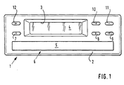
- FIG. 1 shows a flat installation housing having tachograph 1, in the front wall 2 a recess. 3 is formed, which serves as a window for the display means of the tachograph 1,
- a recess. 3 is formed, which serves as a window for the display means of the tachograph 1,
- LCD device 4 is used for an LCD device 4 .
- 5 is a bar or a Front wall element refers to which part of a drawer 6, which in the Housing of the tachograph 1 is slidably guided, represents.
- 7, 8, 9, 10, 11 and 12 denote keys, of which 7 and 8 in themselves conventional tachographs correspond to conventional rotary knobs, that is, with which the working time break, driving time and other working hours of Driver and front passenger are adjustable.
- Button 9 allows menu selection, the keys 10 and 11 are for forward and backward scrolling in the Records of the selected menu.
- the Drawer 6 unlocks and advances the drawer into one convenient position to be triggered.
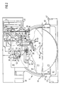
- the plan view, Figure 2 shows the drawer 6 with the for Description of the environment of innovation required components and a multi-track registration device 13, which in the selected in Figure 2 Looking towards the drawer 6 together with a not shown Speed registration device below one in the housing of the Tachograph 1 attached, not shown mounting board arranged is.
- the multi-track registration device 13 consists essentially of one Carriage 14 which is slidably mounted on a guide rod 15 and by means of a mounted on the mounting board engine, the geared connection with a formed on the carriage 14 Rack 16 is driven continuously oscillating.
- an arm formed on the carriage 14 denotes a pen 25 of the multi-track registration device.
- Another on the sled 14 molded arm 26 is used, which will be explained in more detail below, as Carrier, wherein in this function an integrally formed on the arm 26 pin 27 passes through a slot 28, which in a in the drawer. 6 used bridge 29 is formed.
- the directions of movement of the Driver or the pin 27 are in Figure 3 with a double arrow B. symbolically represented.
- Diagram disk 23 on a centering and driving mandrel 30 recorded, which is driven in the right time.
- the Distance plate 38 is, as the figure 2 shows, for the purpose of changing the underlying graph plate 37 in the bridge 29 and thus in the Drawer 6 in a suitable manner by means of bearing journals 40 and 41 pivotally stored and supported by molded tabs 42 and 43 optionally using alignment pins and / or a detachable, also the alignment of the spacer plate 38 serving, not closer joint between the tabs 42, 43 and a designated Stiffening edge 44 of the drawer 6 on this.
- One in the drawer 6 molded recessed grip 45 is used to grip the spacer plate 38 and the Diagram disks 23, 37 in particular during their removal.
- the transmission lever 51 by attaching to the axis 55th and brought by pivoting in its functional position, wherein suitable openings or countersinks 61 and 62 must be provided.
- a designated 63 the arm 56 acting spring holds the Transmission lever 51 in a normal position in which the arm 57 by means of of the finger-shaped extension 58 on a to the adjusting means 53rd belonging eccentric 64 is supported.
- the eccentric 64 forms together with a locking and adjusting lever 65, a component which is on a ground 66th the free edge 60 integrally formed pin 67 is rotatably mounted.
- At 68 is an on the floor 66 of the free cast 60 building up with a Rastveriereung provided toothed segment, with which the Rastund Lever 65, suitably stepped and with a notch is formed, cooperates.
- the free end of the rest and Adjusting lever 65 engages through a slot-shaped, in the figures 2 and 3 visible opening, which in the injection molding of the F Glaskung 60 and one of these associated arcuate recess 69 automatically arises, on the underside of the bridge 29 through, so that the eccentric 64th as well as the transmission lever 51ssnostind on the pin 67th is stored.
- the described Adjusting means adjusting the position of the arm 56 with respect to the serve entrainment pin 27.
- the registration element 39 in FIG arranged in the spacer plate 38 recess 70, and on a molded-on pin 71 rotatably mounted.
- a designated 72, also on the spacer plate 38 molded Rasthacken serves the axial Securing of a lever 73 and an embedded in the lever 73, a pen 74 bearing leaf spring 75 existing registration 39th
- a pen by means of a suitable version the leaf spring 75 attached sapphire pin use.
- the between the Transmission lever 51 and the registration member 39 provided coupling 54th is formed as a hinge and has an integrally formed on the lever 73 axis 76, on which a formed on the arm 57 of the transmission lever 51 Fork 77 attacks.
- the inner surfaces of the fork legs 78th and 79 arched or bevelled trained so that each one punk-shaped contact between the axis 76 and the legs of the fork 77 results.
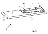
- a Registrierorgans 80 is designed as a slide, for its storage a designed accordingly cutout in the spacer plate 38 must become.
- This embodiment allows in contrast to As described above, the recording is more straightforward Chart elements.
- the slider is parallel to each other Guide beads 81 and 82 formed and, for example by Ultrasonic welding a leaf spring 83 attached, which in the slide a suitable recess 84 is assigned. With 85 is one on the leaf spring 83 fixed pen referred.
- An axis designated 86 sets in the same way as the axis 76, a joint element for engaging the Transmission lever 51 is.
Landscapes
- Physics & Mathematics (AREA)
- General Physics & Mathematics (AREA)
- Time Recorders, Dirve Recorders, Access Control (AREA)
- Recording Measured Values (AREA)
- Navigation (AREA)
Description
Die Erfindung betrifft eine Antriebsverbindung für ein Registrierorgan in einem Fahrtschreiber mit einem flachen Einbaugehäuse, in welchem als Aufzeichnungsträger gleichzeitig zwei gleichachsig angeordnete und mittels einer Schublade zwischen einer Einlege-/Entnahmeposition und einer Registrierposition bewegbare, uhrzeitrichtig angetriebene Diagrammscheiben Anwendung finden, ein auf der untenliegenden Diagrammscheibe zur Aufzeichnung von Balkendiagrammen wirksames Registrierorgan an einer den beiden Diagrammscheiben zugeordneten Distanzplatte gelagert ist und die Distanzplatte zum Wechseln der untenliegenden Diagrammscheibe im Körper der Schublade derart schwenkbar angebracht ist, daß sich die geometrische Achse der Distanzplatte in einer Parallellage zu den Diagrammscheiben befindet.The invention relates to a drive connection for a registration member in a tachograph with a flat installation housing, in which as Record carrier simultaneously two coaxially arranged and means a drawer between an insertion / removal position and a Registration position movable, time-correct driven diagram discs Find an application on the chart below Recording of bar graphs effective registrar at a the two diagram discs associated spacer plate is mounted and the Spacer plate for changing the underlying diagram disc in the body the drawer is pivotally mounted such that the geometric Axis of the distance plate in a parallel position to the graph disks located.
Aus der GB-A-1 417 366 und der EP-A-0 328 454 sind sogannte "Kompaktfahrtenschreiber" bekannt. Solche Fahrtenschreiber enthalten im Gegensatz zum Fahrtenschreiber der vorliegenden Erfindung auch einen Tachometer, der zum Einlegen und Entnehmen von Diagrammscheiben mit Teilen des Fahrtschreibers nach oben aufgeklappt werden kann. Die vorgenannten Schriften beschreiben Lösungen für Fahrtschreiber, in die gleichzeitig zwei Diagrammscheiben eingelegt und beschrieben werden können. Bei der erstgenannten Schrift weisen die zu beschreibenden Oberflächen der Diagrammscheiben voneiander weg und liegen jeweils auf einer Seite einer Unterlage auf. In dem aufgeklappten Teil des Fahrtschreibers sind Schreibmittel zum Beschreiben der ersten Diagrammscheibe angeordnet, Schreibmittel zum Beschreiben der zweiten Diagrammscheibe befinden sich im nicht abgeklappten Teil des Fahrtschreibers.Bei der letztgenannten Schrift berühren sich die die zu beschreibenden Oberflächen der Diagrammscheiben in einem ersten Bereich. In einem zweiten Bereich werden die Scheiben voneinander gespeizt und von unabhängig voneinander angetriebenen Schreibmitteln beschrieben.From GB-A-1 417 366 and EP-A-0 328 454 are so-called "Compact tachograph" known. Such tachographs included in the Unlike the tachograph of the present invention also a Tachometer for inserting and removing diagrams with parts of the tachograph can be opened upwards. The aforementioned Writings describe solutions for tachographs, in which two Chart discs can be inserted and described. In the The first mentioned document has the surfaces to be described Diagram disks away from each other and lie on one side of each Underlay. In the unfolded part of the tachograph writing means for Describing the first chart arranged, writing means to Describe the second chart are in the unfolded part of the tachograph descriptive surfaces of the chart disks in a first area. In a second area, the discs are fed from each other and from independently driven writing means described.
Derartige flach konzipierte, als sogenannte Zweifahrergeräte ausgebildete Fahrtschreiber bereiten erhebliche Schwierigkeiten hinsichtlich der räumlichen Anordnung der Antriebsmittel insbesondere aber der Antriebsverbindungen zu dem Zentrier- und Mitnahmedorn der Diagrammscheiben und den verschiedenen auf den beiden Diagrammscheiben wirksamen Registrierorganen sowie der Verriegelung, Fixierung und Entriegelung der Schublade selbst. Ferner müssen solche Fahrtschreiber auf einfache Weise reproduzierbar sein, letzten Endes den Anforderungen der Großserienfertigung genügen und der für die Fahrzeuginstrumentierung ohnehin bestehenden Bedingung eines möglichst geringen Aufwandes gerecht werden, wobei wegen der geforderten Registriergenauigkeit ein relativ hoher Qualitätsstand zu schaffen ist. Das heißt, es sind größere Toleranzadditionen zu vermeiden, Mehrfachnutzungen von Antrieben und Antriebsverbindungen anzustreben und die Anzahl der Bauteile zu reduzieren. Dies gilt insbesondere für die Gestaltung der Antriebsverbindung zu dem auf der untenliegenden Diagrammscheibe wirksamen, räumlich relativ ungünstig gelagerten Registrierorgan.Such flat designed, as so-called two-wheeled devices Trained tachographs present considerable difficulties the spatial arrangement of the drive means in particular but the Drive connections to the centering and driving mandrel of Graphs and the different on the two graphs effective Registrierorganen as well as the locking, fixation and Unlocking the drawer itself. Furthermore, such tachographs must open easy to be reproducible, in the end the requirements of the Large-volume production is sufficient and that for vehicle instrumentation anyway existing condition of the least possible effort fair be, because of the required registration accuracy a relatively high Quality level is to create. That is, they are larger tolerance additions to avoid multiple uses of drives and drive connections to strive for and reduce the number of components. This is especially true for the design of the drive connection to that on the below Chart disk effective, spatially relatively unfavorable stored Registration organ.
Die Aufgabe der vorliegenden Erfindung bestand somit darin eine Antriebsverbindung für das an der Distanzplatte gelagerte Registrierorgan zu schaffen, welcher den vorstehend genannten, sich zum Teil widersprechenden Bedingungen optimal gerecht wird.The object of the present invention was thus a Drive connection for the mounted on the spacer plate registration member create, which the above, partially contradictory Conditions optimally.
Die Lösung der Aufgabe beschreibt der Anspruch 1. Vorteilhafte Ausgestaltungen der Erfindung sind in den Unteransprüchen dargestellt.The solution of the problem is described in claim 1. Advantageous Embodiments of the invention are shown in the subclaims.
Die gefundene Lösung erfüllt die aufgabengemäß gestellten Anforderungen an die gesuchte Antriebsverbindung in vollem Umfange. Insbesondere bietet sie eine zuverlässige Funktion, die auch bei einer weniger sorgfältigen Handhabung der Distanzplatte beim Wechseln der Diagrammscheiben gewährleistet ist. Der Gedanke den Antrieb des in der Distanzplatte gelagerten und auf der untenliegenden Diagrammscheibe wirksamen Registrierorgans vom Schlitten einer Mehrspurregistriervorrichtung abzugreifen, die der obenliegenden Diagrammscheibe zugeordnet ist, vermeidet einen separaten Antrieb für das in der Distanzplatte gelagerte Registrierorgan und eine erheblich größere Anzahl von Bauelementen in der dann erforderlichen Getriebeverbindung. Hervorzuheben ist ferner, daß innerhalb der Antriebsverbindung kein Versatzproblem auftritt, da ein Einkuppelvorgang beim Verschwenken der Distanzplatte fehlt. Auf der anderen Seite ist die Mitnahmeposition zwischen dem Schlitten der Mehrspurregistriervorrichtung und dem Übertragungshebel relativ genau festgelegt, da der Schlitten in bezug auf die Lage des auf dem Schlitten angeordneten Schreibstiftes zu den auf den Diagrammscheiben aufzuzeichnenden Registrierspuren justiert werden muß und die Schublade, in welcher der Übertragungshebel gelagert ist, beim Schließen mit Mitteln zusammenwirkt, die eine genaue Lagefixierung der Schublade in der Registrierposition ermöglichen.The found solution fulfills the task Requirements for the desired drive connection in full scale. In particular, it provides a reliable function, even with a less Careful handling of the spacer plate when changing the Chart is guaranteed. The thought of driving in the Spacer plate stored and on the bottom diagram disc effective registration member of the carriage of a multi-track registration device which is assigned to the chart above, avoids a separate drive for the mounted in the spacer plate Registrierorgan and a considerably larger number of components in the then required transmission connection. It should also be emphasized that within the drive connection no offset problem occurs because a Coupling process when pivoting the spacer plate is missing. On the the other side is the driving position between the carriage of Mehrspurregistriervorrichtung and the transmission lever relatively accurate set as the carriage relative to the location of the carriage arranged pen to those on the chart discs to be recorded registration tracks and the drawer, in which the transfer lever is mounted, when closing with funds interacts, which is an exact location fixation of the drawer in the Enable registration position.
Im folgenden sei die Erfindung anhand von Zeichnungen erläutert. Es zeigen:
- Figur 1
- eine Frontansicht eines die Erfindung beinhaltenden Fahrtschreibers,
Figur 2- eine Draufsicht auf die Schublade des Fahrtschreibers gemäß Figur 1 mit Freischnitten und mit einer Zuordnung einer Mehrspurregistriervorrichtung,
Figur 3- eine bezogen auf die
Figur 2 Untersicht von Distanzplatte und Brücke, Figur 4- ein weiteres Ausführungsbeispiel eines der untenliegenden Diagrammscheibe zugeordneten Registrierorgans.
- FIG. 1
- a front view of a tachograph incorporating the invention,
- FIG. 2
- a top view of the drawer of the tachograph according to Figure 1 with cutouts and with an assignment of a multi-track registration,
- FIG. 3
- one with reference to the figure 2 bottom view of spacer plate and bridge,
- FIG. 4
- a further embodiment of the underlying chart diagram associated registration.
Die Frontansicht, Figur 1, zeigt einen ein flaches Einbaugehäuse
aufweisenden Fahrtschreiber 1, in dessen Frontwand 2 eine Aussparung 3
ausgebildet ist, die als Fenster für die Anzeigemittel des Fahrtschreibers 1,
beispielsweise für eine LCD-Vorrichtung 4 dient. Mit 5 ist eine Leiste bzw. ein
Frontwandelement bezeichnet, welches Teil einer Schublade 6, die in dem
Gehäuse des Fahrtschreibers 1 verschiebbar geführt ist, darstellt. 7, 8, 9, 10,
11 und 12 bezeichnen Tasten, von denen 7 und 8 den an sich bei
herkömmlichen Fahrtschreibern üblichen Drehknöpfen entsprechen, das heißt,
mit denen die Arbeitszeitarten Pause, Lenkzeit und andere Arbeitszeiten von
Fahrer und Beifahrer einstellbar sind. Die Taste 9 ermöglicht eine Menüwahl,
die Tasten 10 und 11 dienen dem Vor- und Rückwärtsblättern in den
Datensätzen des jeweils angewählten Menüs. Mit der Taste 12 kann die
Schublade 6 entriegelt und ein Vorschieben der Schublade in eine
griffgünstige Position ausgelöst werden.The front view, Figure 1, shows a flat installation housing
having tachograph 1, in the front wall 2 a recess. 3
is formed, which serves as a window for the display means of the tachograph 1,
For example, for an
Die Draufsicht, Figur 2, zeigt die Schublade 6 mit den für die
Beschreibung des Umfeldes der Neuerung erforderlichen Bauelementen und
einer Mehrspurregistriervorrichtung 13, die in der in Figur 2 gewählten
Blickrichtung auf die Schublade 6 gemeinsam mit einer nicht dargestellten
Geschwindigkeitsregistriervorrichtung unterhalb einer im Gehäuse des
Fahrtschreibers 1 befestigten, nicht dargestellten Montageplatine angeordnet
ist. Die Mehrspurregistriervorrichtung 13 besteht im wesentlichen aus einem
Schlitten 14, welcher auf einer Führungsstange 15 verschiebbar gelagert ist
und mittels eines auf der Montageplatine befestigten Motors, der in
getrieblicher Verbindung mit einer an dem Schlitten 14 ausgebildeten
Zahnstange 16 steht, kontinuierlich oszillierend angetrieben wird. Über einen
Arm 17 und eine Schenkelfeder 18 steht der Schlitten 14 mit einer
Steuerwelle 19 in Wirkverbindung, welcher ein nicht dargesteller Stellmotor
zugeordnet ist, der getrieblich (Pfeil A) mit einem auf der Steuerwelle 19
befestigten Zahnrad 20 verbunden ist. Mit 21 und 22 sind an der Steuerwelle
19 angeformte Nocken bezeichnet, von denen eine, 21, dem Schlitten 14, die
andere, 22, einem gleichartigen Schlitten der nicht dargestellten
Geschwindigkeitsregistriervorrichtung zugeordnet ist. Die Nocken 21 und 22
dienen dem Verschwenken der Schlitten auf der Führungsstange 15 und
bezüglich der obenliegenden Diagrammscheibe 23 somit dem Anheben und
Absenken der Schreibstifte. Das Anheben sämtlicher Schreibstifte muß
selbstverständlich dann erfolgen, wenn die Schublade 6 geöffnet werden soll.
Bei der Mehrspurregistriervorrichtung ist das Anheben außerdem wenigstens
beim Wechsel von einer Registrierspur in die nächste erforderllich. Mit 24 ist
ein am Schlitten 14 ausgebildeter Arm bezeichnet, der einen Schreibstift 25
der Mehrspurregistriervorrichtung trägt. Ein weiterer am Schlitten 14
angeformter Arm 26 dient, was nachfolgend noch näher erläutert wird, als
Mitnehmer, wobei in dieser Funktion ein an dem Arm 26 angeformter Zapfen
27 durch ein Langloch 28 hindurchgreift, welches in einer in der Schublade 6
eingesetzten Brücke 29 ausgebildet ist. Die Bewegungsrichtungen des
Mitnehmers bzw. des Zapfens 27 sind in Figur 3 mit einem Doppelpfeil B
symbolisch dargestellt.The plan view, Figure 2, shows the
Wie die Figur 2 ferner zeigt, ist die bereits erwähnte obenliegende
Diagrammscheibe 23 auf einem Zentrier- und Mitnahmedorn 30
aufgenommen, der uhrzeitrichtig angetrieben wird. Der Übersichtlichkeit
halber ist das in der Schublade 6 gelagerte Getriebe zwischen dem Zentrierund
Mitnahmedorn 30 und einem Motor 31 nur teilweise dargestellt. Dabei
handelt es sich um ein Zahnrad 32, ein Zahnradpaar 33/34 und ein auf der
Welle des Rotors 35 des Motors 31 befestigtes Ritzel 36. Ergänzend sei noch
erwähnt, daß eine untenliegende, in dem betreffenden Zweifahrergerät dem
Beifahrer zugeordnete Diagrammscheibe 37 ebenfalls auf dem Zentrier- und
Mitnahmedorn 30 aufgenommen ist und von diesem uhrzeitrichtig angetrieben
wird und daß die getriebliche Verbindung zwischen dem Motor 31 und dem
Zentrier- und Mitnahmedorn sich im Boden der Schublade 6, das heißt
unterhalb der untenliegenden Diagrammscheibe 37 befindet. Mit 38 ist eine
zwischen den Diagrammscheiben 23 und 37 befindliche Distanzplatte
bezeichnet, welche einerseits der obenliegenden Diagrammscheibe 23 als
Registrierunterlage andererseits einem auf der untenliegenden
Diagrammscheibe aufzeichnenden Registrierorgan 39 als Träger dient. Die
Distanzplatte 38 ist, wie die Figur 2 zeigt, zum Zwecke des Wechselns der
untenliegenden Diagrammscheibe 37 in der Brücke 29 und somit in der
Schublade 6 in geeigneter Weise mittels Lagerzapfen 40 und 41 schwenkbar
gelagert und stützt sich mittels angeformter Lappen 42 und 43
gegebenenfalls unter Verwendung von Ausrichtstiften und/oder einer
lösbaren, ebenfalls dem Ausrichten der Distanzplatte 38 dienenden, nicht
näher bezeichneten Fügeverbindung zwischen den Lappen 42, 43 und einem
Versteifungsrand 44 der Schublade 6 auf dieser ab. Eine in der Schublade 6
ausgeformte Griffmulde 45 dient dem Greifen der Distanzplatte 38 und der
Diagrammscheiben 23, 37 insbesondere bei deren Entnahme. Mit 46 und 47
sind der frontseitigen Fixierung der Schublade 6 dienende Konturen
bezeichnet; 48 und 49 stellen mit geeigneten Schlitzen versehene
Führungswangen dar. Der Vollständigkeit halber sei noch erwähnt, daß der
Durchmesser einer in der Distanzplatte 38 ausgebildeten Öffnung 50 derart
gewählt werden muß, daß eine freie Drehbewegung des exzentrisch
ausgebildeten Zentrier- und Mitnahmedorns 30 sowie ein ungehindertes
Verschwenken der Distanzplatte 38 in jeder Stellung des Zentrier- und
Mitnahmedorns 30 gewährleistet ist. As FIG. 2 further shows, the above-mentioned one is already mentioned
Mit 51 ist ein die getriebliche Verbindung zwischen der
Mehrspurregistriervorrichtung 13 und dem Registrierorgan 39 bildender
Übertragungshebel bezeichnet, welcher in einer in der Brücke 29
vorgesehenen Freisenkung 52 angeordnet ist und welchem Justiermittel 53
zugeordnet sind. Die Kupplung zwischen dem Übertragungshebel 51 und dem
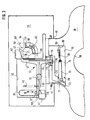
Registrierorgan 39 ist mit 54 bezeichnet. Die Untersicht, Figur 3, verdeutlicht
die Anordnung des Übertragungshebels 51 innerhalb der Freisenkung 52.
Dabei ist der zweiarmige Übertragungshebel 51 auf einer an der Brücke 29
angeformten Achse 55 drehbar und axial selbstsichernd dadurch gelagert, daß
an den Armen 56 und 57 angeformte fingerförmige Fortsätze 58 und 59 in
eine Freisenkung 60 eingreifen bzw. die Brücke 29 hintergreifen. Bei der
Montage wird der Übertragungshebel 51 durch Aufstecken auf die Achse 55
und durch Verschwenken in seine Funktionsstellung gebracht, wobei
geeignete Durchbrüche oder Senkungen 61 und 62 vorgesehen sein müssen.
Eine mit 63 bezeichnete, am Arm 56 angreifende Feder hält den
Übertragungshebel 51 in einer Grundstellung, in der sich der Arm 57 mittels
des fingerförmigen Fortsatzes 58 auf einem zu den Justiermitteln 53
gehörenden Exzenter 64 abstützt. Der Exzenter 64 bildet zusammen mit
einem Rast- und Stellhebel 65 ein Bauteil, welches auf einem am Boden 66
der Freisenkung 60 angeformten Zapfen 67 drehbar gelagert ist. Mit 68 ist
ein auf dem Boden 66 der Freisenkung 60 aufbauendes mit einer
Rastverzahnung versehenes Zahnsegment bezeichnet, mit welchem der Rastund
Stellhebel 65, der in geeigneter Weise gestuft und mit einer Kerbe
versehen ausgebildet ist, zusammenwirkt. Das freie Ende des Rast- und
Stellhebels 65 greift durch eine schlitzförmige, in den Figuren 2 und 3
sichtbare Öffnung, die bei der spritzgießtechnischen Bildung der Freisenkung
60 und einer dieser zugeordneten bogenförmigen Vertiefung 69 automatisch
entsteht, auf die Unterseite der Brücke 29 durch, so daß der Exzenter 64
ebenso wie der Übertragungshebel 51 selbssichernd auf dem Zapfen 67
gelagert ist. Der Vollständigkeit halber sei erwähnt, daß die beschriebenen
Justiermittel, der Einstellung der Lage des Armes 56 in Bezug auf den
mitnehmenden Zapfen 27 dienen.With 51 is a the geared connection between the
Wie aus der Figur 3 ferner noch hervorgeht ist das Registrierorgan 39 in
einer in der Distanzplatte 38 ausgebildeten Vertiefung 70 angeordnet, und auf
einem angeformten Stift 71 drehbar gelagert. Ein mit 72 bezeichneter,
ebenfalls an der Distanzplatte 38 angeformter Rasthacken dient der axialen
Sicherung des aus einem Hebel 73 und einer in dem Hebel 73 eingebetteten,
einen Schreibstift 74 tragende Blattfeder 75 bestehenden Registrierorgans 39.
Vorzugsweise findet als Schreibstift ein mittels einer geeigneten Fassung an
der Blattfeder 75 befestigter Saphirstift Verwendung. Die zwischen dem
Übertragungshebel 51 und dem Registrierorgan 39 vorgesehen Kupplung 54
ist als Gelenk ausgebildet und weist eine an dem Hebel 73 angeformte Achse
76 auf, an welcher eine am Arm 57 des Übertragungshebels 51 ausgebildete
Gabel 77 angreift. Um wegen ungleicher Hebellängen ein Kippen der Gabel 77
auf der Achse 76 zu ermöglichen sind die Innenflächen der Gabelschenkel 78
und 79 gewölbt oder angeschrägt ausgebildet, so daß sich jeweils eine
punkförmige Berührung zwischen der Achse 76 und den Schenkeln der Gabel
77 ergibt.As can also be seen from FIG. 3, the
Das mit der Figur 4 dargestellte weitere Ausführungsbeispiel eines
Registrierorgans 80 ist als Schieber ausgebildet, zu dessen Lagerung eine
entsprechend gestaltete Freisparung in der Distanzplatte 38 vorgesehen
werden muß. Dieses Ausführungsbeispiel ermöglicht im Gegensatz zum
vorstehend beschriebenen Ausführungsbeispiel das Aufzeichnen geradliniger
Diagrammelemente. Im Einzelnen sind an dem Schieber parallel zueinander
Führungswülste 81 und 82 ausgebildet und zum Beispiel durch
Ultraschallschweißen eine Blattfeder 83 befestigt, welcher in dem Schieber
eine geeignete Vertiefung 84 zugeordnet ist. Mit 85 ist ein an der Blattfeder
83 befestigter Schreibstift bezeichnet. Eine mit 86 bezeichnete Achse stellt in
gleicher Weise wie die Achse 76 ein Gelenkelement für das Einkuppeln des
Übertragungshebels 51 dar. The illustrated with the figure 4 further embodiment of a
In Figur 3 sind symbolisch drei Diagramme dargestellt, die vom
Schreibstift 74 des Registrierorgans 39 auf der untenliegenden
Diagrammscheibe, die in der in Figur 3 dargestellten Untersicht nicht
gezeichnet ist, aufgezeichnet werden. Dabei bedeuten die Diagramme 88 und
89 unterschiedliche Arbeitsarten und das Diagramm 90, das in der erwähnten
Grundstellung des Übertragungshebels 51 aufgezeichnet wird, Pause.In Figure 3, three diagrams are symbolically represented by the
Claims (6)
- Drive connection for a recording elements (39) in a tachograph (1) having a flat installation housing in which two diagram disks (23, 37) which are arranged coaxially, can be moved by means of a drawer (6) between an insertion/removal position and a recording position and can be driven simultaneously at the correct time are applied as recording carriers, a recording element (39) which can act on the bottom diagram disk (37) in order to record bar diagrams (88, 89) is mounted on a spacer plate (38) which is assigned to the two diagram disks (23, 37), and the spacer plate (38) is mounted in a pivotable fashion in the body of the drawer (6) in order to change the bottom diagram disk (37), in that the geometric axis of the bearing of the spacer plate (38) is located in a parallel position to the diagram disks (23, 37), characterized in that, in order to record on the top diagram disk (23), a multitrack recording device (13) is provided with a carriage (14) which supports a writing pin (25) and which is moved to and fro continuously by means of a motor within a recording region comprising a plurality of recording tracks on the diagram disk (23) and in the process the writing pin (25) is lowered briefly onto the diagram disk (23) in order to produce registration elements in the respective recording tracks, and is raised again, in that, when the drawer (6) of the tachograph (1) is closed and in the one end position of the carriage (14) with respect to the recording region of the multitrack recording device (13) on the top diagram disk (23), the carriage (14) and the recording element (39) which is mounted in the spacer plate (39) are operatively connected, and in that in this end position the motor is actuated in such a way that the carriage (14) undergoes excess travel and the registration element (39) which is mounted in the spacer plate (38) is pivoted counter to the effect of a spring (63).
- Drive connection according to Claim 1,
characterized in that a two-armed transmission lever (51), which is pivotably mounted in the drawer (6) parallel to the diagram disks (23, 27), is provided as an operative connection between the recording element (39) which is mounted in the spacer plate (38) and the carriage (14), one arm (57) of said transmission lever (51) being coupled to the recording element (39) in an articulated fashion such that the axis of rotation of the coupling (54) coincides essentially with the geometric axis of the bearing of the spacer plate (38) and a driver (26, 27) which is formed on the carriage (14) acts on the other free arm (56) of said transmission lever (51) when the carriage (14) is in the one end position. - Drive connection according to Claim 2,
characterized in that the coupling (54) which is provided between the in the spacer plate (38) and the transmission lever (51) is formed in that an axis (76), around which a fork (77) which is formed on the transmission lever (51) engages, is formed on the recording element (39). - Drive connection according to Claim 1,
characterized in that the recording element (39) which is mounted in the spacer plate (38) is composed of a lever (73) with a leaf spring (75) which supports a writing pin (74) which is attached thereto. - Drive connection according to Claim 1,
characterized in that the recording element (80) is embodied as a slide which is mounted in the spacer plate (38) and has a leaf spring (83) which is attached thereto and supports a writing pin (85). - Drive connection according to Claim 3,
characterized in that the internal faces of the fork (77) which face the axis (76) of the coupling (54) are shaped in such a way that when the recording element (39) which is mounted in the spacer plate (38) is activated by the transmission lever (51), punctiform contact occurs between the fork (77) and the axis (76).
Applications Claiming Priority (2)
| Application Number | Priority Date | Filing Date | Title |
|---|---|---|---|
| DE19613872A DE19613872A1 (en) | 1996-04-06 | 1996-04-06 | Drive connection for a registration element in a tachograph |
| DE19613872 | 1996-04-06 |
Publications (3)
| Publication Number | Publication Date |
|---|---|
| EP0800151A2 EP0800151A2 (en) | 1997-10-08 |
| EP0800151A3 EP0800151A3 (en) | 1999-05-19 |
| EP0800151B1 true EP0800151B1 (en) | 2005-05-25 |
Family
ID=7790700
Family Applications (1)
| Application Number | Title | Priority Date | Filing Date |
|---|---|---|---|
| EP97104665A Expired - Lifetime EP0800151B1 (en) | 1996-04-06 | 1997-03-19 | Drive connection for a tachograph registering device |
Country Status (3)
| Country | Link |
|---|---|
| EP (1) | EP0800151B1 (en) |
| JP (1) | JP3958825B2 (en) |
| DE (2) | DE19613872A1 (en) |
Families Citing this family (6)
| Publication number | Priority date | Publication date | Assignee | Title |
|---|---|---|---|---|
| DE29621117U1 (en) * | 1996-12-05 | 1997-01-23 | VDO Adolf Schindling AG, 60326 Frankfurt | Adjustment device for the drive connection of a recording element recording bar charts |
| DE29901615U1 (en) * | 1999-01-30 | 1999-04-08 | Mannesmann VDO AG, 60388 Frankfurt | Registration arrangement, especially for tachographs |
| US7318593B2 (en) * | 2004-10-15 | 2008-01-15 | Ford Global Technologies, Llc | Stabilizer bar and bushing assembly |
| CN109147087B (en) * | 2018-07-06 | 2021-03-12 | 凯扬光电(苏州)有限公司 | Vehicle event data recorder with air-purifying function |
| KR102077483B1 (en) | 2019-05-24 | 2020-02-14 | 박태수 | Detachable module for glasses |
| CN110493991A (en) * | 2019-08-28 | 2019-11-22 | 郭宏凯 | A kind of multifunctional running recorder |
Family Cites Families (5)
| Publication number | Priority date | Publication date | Assignee | Title |
|---|---|---|---|---|
| DE2319020C3 (en) * | 1973-04-14 | 1981-04-02 | Kienzle Apparate Gmbh, 7730 Villingen-Schwenningen | Arrangement of a carrier storing a writing element in a tachograph |
| DE3733151A1 (en) * | 1987-09-30 | 1989-04-13 | Mannesmann Kienzle Gmbh | RECORDING DEVICE WITH A FLAT RECESSED HOUSING |
| EP0328454A1 (en) * | 1988-02-10 | 1989-08-16 | Jaeger | Inscription device for a recorder with two diagram discs |
| DE9317101U1 (en) * | 1993-11-09 | 1994-03-03 | Mannesmann Kienzle Gmbh, 78052 Villingen-Schwenningen | Motor vehicle with a tachograph |
| DE4438926A1 (en) * | 1994-10-31 | 1996-05-02 | Mannesmann Kienzle Gmbh | Arrangement of the recording media in a tachograph with a flat installation housing |
-
1996
- 1996-04-06 DE DE19613872A patent/DE19613872A1/en not_active Withdrawn
-
1997
- 1997-03-19 DE DE59712323T patent/DE59712323D1/en not_active Expired - Lifetime
- 1997-03-19 EP EP97104665A patent/EP0800151B1/en not_active Expired - Lifetime
- 1997-04-07 JP JP08794797A patent/JP3958825B2/en not_active Expired - Fee Related
Also Published As
| Publication number | Publication date |
|---|---|
| JP3958825B2 (en) | 2007-08-15 |
| DE19613872A1 (en) | 1997-10-09 |
| EP0800151A2 (en) | 1997-10-08 |
| EP0800151A3 (en) | 1999-05-19 |
| JPH1030937A (en) | 1998-02-03 |
| DE59712323D1 (en) | 2005-06-30 |
Similar Documents
| Publication | Publication Date | Title |
|---|---|---|
| EP0012223B1 (en) | Tachograph | |
| DE4403958C2 (en) | Head positioning device | |
| EP0800151B1 (en) | Drive connection for a tachograph registering device | |
| DE3121502A1 (en) | DRIVE DEVICE FOR A TURNTABLE | |
| DE2707363C3 (en) | ||
| DE4438926A1 (en) | Arrangement of the recording media in a tachograph with a flat installation housing | |
| DE19536515C2 (en) | Tachograph | |
| DE2411515A1 (en) | TACHOGRAPH | |
| EP0247550B1 (en) | Tachograph for motor vehicles | |
| DE69110718T2 (en) | Information playback device. | |
| EP0864137B1 (en) | Tachograph with drawer | |
| EP0330002B1 (en) | Arrangement for the automatic, exactly timed positioning of a bundle of diagram discs for registration in portions, yet continuously | |
| DE2604127A1 (en) | DIAGRAM DISC DRIVE ARRANGEMENT FOR A TACHOGRAPHER | |
| DE19755310C2 (en) | Arrangement for clamping a chart | |
| EP0102595A1 (en) | Method of controlling a recording element | |
| EP0744714B1 (en) | Recording device for tachograph | |
| DE19546029C2 (en) | Tachograph with a writing system for speed records | |
| DE1817340C3 (en) | Registration arrangement for tachographs | |
| EP0935220A2 (en) | Tachograph with a parallelepipedal housing | |
| EP0265595B1 (en) | Disposition for driving a record chart | |
| EP0116125A2 (en) | Mounting method for writing tip of a tachograph | |
| DE277131C (en) | ||
| EP1024349B1 (en) | Registering device, particularly for a tachograph | |
| DE19750683B4 (en) | Adjustment device for the drive connection of a recording element recording bar charts | |
| DE2228124A1 (en) | Tachograph |
Legal Events
| Date | Code | Title | Description |
|---|---|---|---|
| PUAI | Public reference made under article 153(3) epc to a published international application that has entered the european phase |
Free format text: ORIGINAL CODE: 0009012 |
|
| AK | Designated contracting states |
Kind code of ref document: A2 Designated state(s): CH DE FR GB IT LI |
|
| RAP1 | Party data changed (applicant data changed or rights of an application transferred) |
Owner name: MANNESMANN VDO AG |
|
| 17P | Request for examination filed |
Effective date: 19981205 |
|
| PUAL | Search report despatched |
Free format text: ORIGINAL CODE: 0009013 |
|
| AK | Designated contracting states |
Kind code of ref document: A3 Designated state(s): CH DE FR GB IT LI |
|
| RAP1 | Party data changed (applicant data changed or rights of an application transferred) |
Owner name: SIEMENS AKTIENGESELLSCHAFT |
|
| 17Q | First examination report despatched |
Effective date: 20021022 |
|
| GRAP | Despatch of communication of intention to grant a patent |
Free format text: ORIGINAL CODE: EPIDOSNIGR1 |
|
| GRAS | Grant fee paid |
Free format text: ORIGINAL CODE: EPIDOSNIGR3 |
|
| GRAA | (expected) grant |
Free format text: ORIGINAL CODE: 0009210 |
|
| AK | Designated contracting states |
Kind code of ref document: B1 Designated state(s): CH DE FR GB IT LI |
|
| REG | Reference to a national code |
Ref country code: GB Ref legal event code: FG4D Free format text: NOT ENGLISH |
|
| REG | Reference to a national code |
Ref country code: CH Ref legal event code: EP |
|
| REF | Corresponds to: |
Ref document number: 59712323 Country of ref document: DE Date of ref document: 20050630 Kind code of ref document: P |
|
| GBT | Gb: translation of ep patent filed (gb section 77(6)(a)/1977) |
Effective date: 20050719 |
|
| PG25 | Lapsed in a contracting state [announced via postgrant information from national office to epo] |
Ref country code: LI Free format text: LAPSE BECAUSE OF NON-PAYMENT OF DUE FEES Effective date: 20060331 Ref country code: CH Free format text: LAPSE BECAUSE OF NON-PAYMENT OF DUE FEES Effective date: 20060331 |
|
| PLBE | No opposition filed within time limit |
Free format text: ORIGINAL CODE: 0009261 |
|
| STAA | Information on the status of an ep patent application or granted ep patent |
Free format text: STATUS: NO OPPOSITION FILED WITHIN TIME LIMIT |
|
| ET | Fr: translation filed | ||
| 26N | No opposition filed |
Effective date: 20060228 |
|
| REG | Reference to a national code |
Ref country code: CH Ref legal event code: PL |
|
| PGFP | Annual fee paid to national office [announced via postgrant information from national office to epo] |
Ref country code: GB Payment date: 20090325 Year of fee payment: 13 |
|
| PGFP | Annual fee paid to national office [announced via postgrant information from national office to epo] |
Ref country code: IT Payment date: 20090324 Year of fee payment: 13 |
|
| PGFP | Annual fee paid to national office [announced via postgrant information from national office to epo] |
Ref country code: FR Payment date: 20090312 Year of fee payment: 13 |
|
| GBPC | Gb: european patent ceased through non-payment of renewal fee |
Effective date: 20100319 |
|
| REG | Reference to a national code |
Ref country code: FR Ref legal event code: ST Effective date: 20101130 |
|
| PG25 | Lapsed in a contracting state [announced via postgrant information from national office to epo] |
Ref country code: FR Free format text: LAPSE BECAUSE OF NON-PAYMENT OF DUE FEES Effective date: 20100331 |
|
| PG25 | Lapsed in a contracting state [announced via postgrant information from national office to epo] |
Ref country code: GB Free format text: LAPSE BECAUSE OF NON-PAYMENT OF DUE FEES Effective date: 20100319 Ref country code: IT Free format text: LAPSE BECAUSE OF NON-PAYMENT OF DUE FEES Effective date: 20100319 |
|
| PGFP | Annual fee paid to national office [announced via postgrant information from national office to epo] |
Ref country code: DE Payment date: 20140331 Year of fee payment: 18 |
|
| REG | Reference to a national code |
Ref country code: DE Ref legal event code: R119 Ref document number: 59712323 Country of ref document: DE |
|
| PG25 | Lapsed in a contracting state [announced via postgrant information from national office to epo] |
Ref country code: DE Free format text: LAPSE BECAUSE OF NON-PAYMENT OF DUE FEES Effective date: 20151001 |