EP0800151B1 - Antriebsverbindung für ein Registrierorgan in einem Fahrtschreiber - Google Patents
Antriebsverbindung für ein Registrierorgan in einem Fahrtschreiber Download PDFInfo
- Publication number
- EP0800151B1 EP0800151B1 EP97104665A EP97104665A EP0800151B1 EP 0800151 B1 EP0800151 B1 EP 0800151B1 EP 97104665 A EP97104665 A EP 97104665A EP 97104665 A EP97104665 A EP 97104665A EP 0800151 B1 EP0800151 B1 EP 0800151B1
- Authority
- EP
- European Patent Office
- Prior art keywords
- spacer plate
- recording
- carriage
- drive connection
- drawer
- Prior art date
- Legal status (The legal status is an assumption and is not a legal conclusion. Google has not performed a legal analysis and makes no representation as to the accuracy of the status listed.)
- Expired - Lifetime
Links
Images
Classifications
-
- G—PHYSICS
- G07—CHECKING-DEVICES
- G07C—TIME OR ATTENDANCE REGISTERS; REGISTERING OR INDICATING THE WORKING OF MACHINES; GENERATING RANDOM NUMBERS; VOTING OR LOTTERY APPARATUS; ARRANGEMENTS, SYSTEMS OR APPARATUS FOR CHECKING NOT PROVIDED FOR ELSEWHERE
- G07C5/00—Registering or indicating the working of vehicles
- G07C5/08—Registering or indicating performance data other than driving, working, idle, or waiting time, with or without registering driving, working, idle or waiting time
- G07C5/12—Registering or indicating performance data other than driving, working, idle, or waiting time, with or without registering driving, working, idle or waiting time in graphical form
-
- G—PHYSICS
- G01—MEASURING; TESTING
- G01P—MEASURING LINEAR OR ANGULAR SPEED, ACCELERATION, DECELERATION, OR SHOCK; INDICATING PRESENCE, ABSENCE, OR DIRECTION, OF MOVEMENT
- G01P1/00—Details of instruments
- G01P1/12—Recording devices
- G01P1/122—Speed recorders
- G01P1/125—Speed recorders with recording discs
Definitions
- the invention relates to a drive connection for a registration member in a tachograph with a flat installation housing, in which as Record carrier simultaneously two coaxially arranged and means a drawer between an insertion / removal position and a Registration position movable, time-correct driven diagram discs Find an application on the chart below Recording of bar graphs effective registrar at a the two diagram discs associated spacer plate is mounted and the Spacer plate for changing the underlying diagram disc in the body the drawer is pivotally mounted such that the geometric Axis of the distance plate in a parallel position to the graph disks located.
- writing means to Describe the second chart are in the unfolded part of the tachograph descriptive surfaces of the chart disks in a first area. In a second area, the discs are fed from each other and from independently driven writing means described.
- the object of the present invention was thus a Drive connection for the mounted on the spacer plate registration member create, which the above, partially contradictory Conditions optimally.
- the found solution fulfills the task Requirements for the desired drive connection in full scale. In particular, it provides a reliable function, even with a less Careful handling of the spacer plate when changing the Chart is guaranteed.
- the thought of driving in the Spacer plate stored and on the bottom diagram disc effective registration member of the carriage of a multi-track registration device which is assigned to the chart above avoids a separate drive for the mounted in the spacer plate Registrierorgan and a considerably larger number of components in the then required transmission connection. It should also be emphasized that within the drive connection no offset problem occurs because a Coupling process when pivoting the spacer plate is missing.
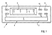
- FIG. 1 shows a flat installation housing having tachograph 1, in the front wall 2 a recess. 3 is formed, which serves as a window for the display means of the tachograph 1,
- a recess. 3 is formed, which serves as a window for the display means of the tachograph 1,
- LCD device 4 is used for an LCD device 4 .
- 5 is a bar or a Front wall element refers to which part of a drawer 6, which in the Housing of the tachograph 1 is slidably guided, represents.
- 7, 8, 9, 10, 11 and 12 denote keys, of which 7 and 8 in themselves conventional tachographs correspond to conventional rotary knobs, that is, with which the working time break, driving time and other working hours of Driver and front passenger are adjustable.
- Button 9 allows menu selection, the keys 10 and 11 are for forward and backward scrolling in the Records of the selected menu.
- the Drawer 6 unlocks and advances the drawer into one convenient position to be triggered.
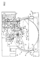
- the plan view, Figure 2 shows the drawer 6 with the for Description of the environment of innovation required components and a multi-track registration device 13, which in the selected in Figure 2 Looking towards the drawer 6 together with a not shown Speed registration device below one in the housing of the Tachograph 1 attached, not shown mounting board arranged is.
- the multi-track registration device 13 consists essentially of one Carriage 14 which is slidably mounted on a guide rod 15 and by means of a mounted on the mounting board engine, the geared connection with a formed on the carriage 14 Rack 16 is driven continuously oscillating.
- an arm formed on the carriage 14 denotes a pen 25 of the multi-track registration device.
- Another on the sled 14 molded arm 26 is used, which will be explained in more detail below, as Carrier, wherein in this function an integrally formed on the arm 26 pin 27 passes through a slot 28, which in a in the drawer. 6 used bridge 29 is formed.
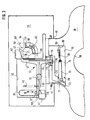
- the directions of movement of the Driver or the pin 27 are in Figure 3 with a double arrow B. symbolically represented.
- Diagram disk 23 on a centering and driving mandrel 30 recorded, which is driven in the right time.
- the Distance plate 38 is, as the figure 2 shows, for the purpose of changing the underlying graph plate 37 in the bridge 29 and thus in the Drawer 6 in a suitable manner by means of bearing journals 40 and 41 pivotally stored and supported by molded tabs 42 and 43 optionally using alignment pins and / or a detachable, also the alignment of the spacer plate 38 serving, not closer joint between the tabs 42, 43 and a designated Stiffening edge 44 of the drawer 6 on this.
- One in the drawer 6 molded recessed grip 45 is used to grip the spacer plate 38 and the Diagram disks 23, 37 in particular during their removal.
- the transmission lever 51 by attaching to the axis 55th and brought by pivoting in its functional position, wherein suitable openings or countersinks 61 and 62 must be provided.
- a designated 63 the arm 56 acting spring holds the Transmission lever 51 in a normal position in which the arm 57 by means of of the finger-shaped extension 58 on a to the adjusting means 53rd belonging eccentric 64 is supported.
- the eccentric 64 forms together with a locking and adjusting lever 65, a component which is on a ground 66th the free edge 60 integrally formed pin 67 is rotatably mounted.
- At 68 is an on the floor 66 of the free cast 60 building up with a Rastveriereung provided toothed segment, with which the Rastund Lever 65, suitably stepped and with a notch is formed, cooperates.
- the free end of the rest and Adjusting lever 65 engages through a slot-shaped, in the figures 2 and 3 visible opening, which in the injection molding of the F Glaskung 60 and one of these associated arcuate recess 69 automatically arises, on the underside of the bridge 29 through, so that the eccentric 64th as well as the transmission lever 51ssnostind on the pin 67th is stored.
- the described Adjusting means adjusting the position of the arm 56 with respect to the serve entrainment pin 27.
- the registration element 39 in FIG arranged in the spacer plate 38 recess 70, and on a molded-on pin 71 rotatably mounted.
- a designated 72, also on the spacer plate 38 molded Rasthacken serves the axial Securing of a lever 73 and an embedded in the lever 73, a pen 74 bearing leaf spring 75 existing registration 39th
- a pen by means of a suitable version the leaf spring 75 attached sapphire pin use.
- the between the Transmission lever 51 and the registration member 39 provided coupling 54th is formed as a hinge and has an integrally formed on the lever 73 axis 76, on which a formed on the arm 57 of the transmission lever 51 Fork 77 attacks.
- the inner surfaces of the fork legs 78th and 79 arched or bevelled trained so that each one punk-shaped contact between the axis 76 and the legs of the fork 77 results.
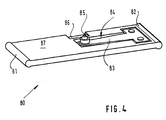
- a Registrierorgans 80 is designed as a slide, for its storage a designed accordingly cutout in the spacer plate 38 must become.
- This embodiment allows in contrast to As described above, the recording is more straightforward Chart elements.
- the slider is parallel to each other Guide beads 81 and 82 formed and, for example by Ultrasonic welding a leaf spring 83 attached, which in the slide a suitable recess 84 is assigned. With 85 is one on the leaf spring 83 fixed pen referred.
- An axis designated 86 sets in the same way as the axis 76, a joint element for engaging the Transmission lever 51 is.
Landscapes
- Physics & Mathematics (AREA)
- General Physics & Mathematics (AREA)
- Time Recorders, Dirve Recorders, Access Control (AREA)
- Recording Measured Values (AREA)
- Navigation (AREA)
Description
- Figur 1
- eine Frontansicht eines die Erfindung beinhaltenden Fahrtschreibers,
- Figur 2
- eine Draufsicht auf die Schublade des Fahrtschreibers gemäß Figur 1 mit Freischnitten und mit einer Zuordnung einer Mehrspurregistriervorrichtung,
- Figur 3
- eine bezogen auf die Figur 2 Untersicht von Distanzplatte und Brücke,
- Figur 4
- ein weiteres Ausführungsbeispiel eines der untenliegenden Diagrammscheibe zugeordneten Registrierorgans.
Claims (6)
- Antriebsverbindung für ein Registrierorgan (39) in einem Fahrtschreiber (1) mit einem flachen Einbaugehäuse, in welchem als Aufzeichnungsträger gleichzeitig zwei gleichachsig angeordnete und mittels einer Schublade (6) zwischen einer Einlege-/Entnahmeposition und einer Registrierposition bewegbare, uhrzeitrichtig angetriebene Diagrammscheiben (23,37) Anwendung finden, ein auf der untenliegenden Diagrammscheibe (37) zur Aufzeichnung von Balkendiagrammen (88,89) wirksames Registrierorgan (39) an einer den beiden Diagrammscheiben (23,37) zugeordnetenDistanzplatte (38) gelagert ist und die Distanzplatte (38) zum Wechseln der untenliegenden Diagrammscheibe (37) im Körper der Schublade (6) derart schwenkbar angebracht ist, daß sich die geometrische Achse der Lagerung der Distanzplatte (38) in einer Parallellage zu den Diagrammscheiben (23,37) befindet
dadurch gekennzeichnet, daß für das Aufzeichnen auf der obenliegenden Diagrammscheibe (23) eine Mehrspurregistriervorrichtung (13) mit einem einen Schreibstift (25) tragenden Schlitten (14) vorgesehen ist, welcher mittels eines Motors innerhalb eines mehrere Registrierspuren auf der Diagrammscheibe (23) umfassenden Registrierbereiches kontinuierlich hin- und herbewegt und dabei der Schreibstift (25) zur Erzeugung von Aufzeichnungselementen in den jeweiligen Registrierspuren kurzzeitig auf die Diagrammscheibe (23) abgesenkt und wieder angehoben wird,
daß bei geschlossener Schublade (6) des Fahrtschreibers (1) in der einen Endstellung des Schlittens (14) bezogen auf den Registrierbereich der Mehrspurregistriervorrichtung (13) auf der obenliegenden Diagrammscheibe (23) der Schlitten (14) und das in der Distanzplatte (38) gelagerte Registrierorgan (39) in Wirkverbindung stehen und
daß der Motor in dieser Endstellung derart angesteuert wird, daß der Schlitten (14) einen Überhub ausführt und das in der Distanzplatte (38) gelagerte Registrierorgan (39) gegen die Wirkung einer Feder (63) verschwenkt wird. - Antriebsverbindung nach Anspruch 1,
dadurch gekennzeichnet, daß zwischen dem in der Distanzplatte (38) gelagerten Registrierorgan (39) und dem Schlitten (14) ein in der Schublade (6) parallel zu den Diagrammscheiben (23. 37) schwenkbar gelagerter zweiarmiger Übertragungshebel (51) als Wirkverbindung vorgesehen ist, dessen einer Arm (57) mit dem Registrierorgan (39) derart gelenkig gekuppelt ist, daß die Drehachse der Kupplung (54) im wesentlichen mit der geometrischen Achse der Lagerung der Distanzplatte (38) zusammenfält und an dessen anderem freien Arm (56) ein an dem Schlitten (14) ausgebildeter Mitnehmer (26, 27) angreift, wenn sich der Schlitten (14) in der einen Endstellung befindet. - Antriebsverbindung nach Anspruch 2,
dadurch gekennzeichnet, daß die zwischen dem in der Distanzplatte (38) und dem Übertragungshebel (51) vorgesehene Kupplung (54) dadurch gebildet ist, daß an dem Registrierorgan (39) eine Achse (76) angeformt ist, die von einer am Übertragungshebel (51) ausgebildeten Gabel (77) umgriffen wird - Antriebsverbindung nach Anspruch 1
dadurch gekennzeichnet, daß das in der Distanzplatte (38) gelagerte Registrierorgan (39) aus einem Hebel (73) mit einer daran befestigten einen Schreibstift (74) tragenden Blattfeder (75) besteht. - Antriebsverbindung nach Anspruch 1,
dadurch gekennzeichnet, daß das Registrierorgan (80) als ein in der Distanzplatte (38) gelagerter Schieber mit einer darauf befestigten, einen Schreibstift (85) tragenden Blattfeder (83) ausgebildet ist. - Antriebsverbindung nach Anspruch 3,
dadurch gekennzeichnet, daß die der Achse (76) der Kupplung (54) zugewandten Innenflächen der Gabel (77) derart gestaltet sind, daß beim Betätigen des in der Distanzplatte (38) gelagerten Registrierorgans (39) durch den Übertragungshebel (51) zwischen der Gabel (77) und der Achse (76) eine punktförmige Berührung gegeben ist.
Applications Claiming Priority (2)
| Application Number | Priority Date | Filing Date | Title |
|---|---|---|---|
| DE19613872A DE19613872A1 (de) | 1996-04-06 | 1996-04-06 | Antriebsverbindung für ein Registrierorgan in einem Fahrtschreiber |
| DE19613872 | 1996-04-06 |
Publications (3)
| Publication Number | Publication Date |
|---|---|
| EP0800151A2 EP0800151A2 (de) | 1997-10-08 |
| EP0800151A3 EP0800151A3 (de) | 1999-05-19 |
| EP0800151B1 true EP0800151B1 (de) | 2005-05-25 |
Family
ID=7790700
Family Applications (1)
| Application Number | Title | Priority Date | Filing Date |
|---|---|---|---|
| EP97104665A Expired - Lifetime EP0800151B1 (de) | 1996-04-06 | 1997-03-19 | Antriebsverbindung für ein Registrierorgan in einem Fahrtschreiber |
Country Status (3)
| Country | Link |
|---|---|
| EP (1) | EP0800151B1 (de) |
| JP (1) | JP3958825B2 (de) |
| DE (2) | DE19613872A1 (de) |
Families Citing this family (6)
| Publication number | Priority date | Publication date | Assignee | Title |
|---|---|---|---|---|
| DE29621117U1 (de) * | 1996-12-05 | 1997-01-23 | VDO Adolf Schindling AG, 60326 Frankfurt | Justiervorrichtung für die Antriebsverbindung eines Balkendiagramme aufzeichnenden Registrierorgans |
| DE29901615U1 (de) * | 1999-01-30 | 1999-04-08 | Mannesmann VDO AG, 60388 Frankfurt | Registrieranordnung, insbesondere für Fahrtschreiber |
| US7318593B2 (en) * | 2004-10-15 | 2008-01-15 | Ford Global Technologies, Llc | Stabilizer bar and bushing assembly |
| CN109147087B (zh) * | 2018-07-06 | 2021-03-12 | 凯扬光电(苏州)有限公司 | 一种具有净化空气功能的行车记录仪 |
| KR102077483B1 (ko) | 2019-05-24 | 2020-02-14 | 박태수 | 안경에 탈부착 가능한 탈부착 모듈 |
| CN110493991A (zh) * | 2019-08-28 | 2019-11-22 | 郭宏凯 | 一种多功能行车记录仪 |
Family Cites Families (5)
| Publication number | Priority date | Publication date | Assignee | Title |
|---|---|---|---|---|
| DE2319020C3 (de) * | 1973-04-14 | 1981-04-02 | Kienzle Apparate Gmbh, 7730 Villingen-Schwenningen | Anordnung eines ein Schreiborgan lagernden Trägers in einem Fahrtschreiber |
| DE3733151A1 (de) * | 1987-09-30 | 1989-04-13 | Mannesmann Kienzle Gmbh | Registriergeraet mit einem flachen einbaugehaeuse |
| EP0328454A1 (de) * | 1988-02-10 | 1989-08-16 | Jaeger | Schreibvorrichtung für ein Registriergerät mit zwei Diagrammscheiben |
| DE9317101U1 (de) * | 1993-11-09 | 1994-03-03 | Mannesmann Kienzle Gmbh, 78052 Villingen-Schwenningen | Kraftfahrzeug mit einem Fahrtschreiber |
| DE4438926A1 (de) * | 1994-10-31 | 1996-05-02 | Mannesmann Kienzle Gmbh | Anordnung der Aufzeichnungsträger in einem Fahrtschreiber mit einem flachen Einbaugehäuse |
-
1996
- 1996-04-06 DE DE19613872A patent/DE19613872A1/de not_active Withdrawn
-
1997
- 1997-03-19 EP EP97104665A patent/EP0800151B1/de not_active Expired - Lifetime
- 1997-03-19 DE DE59712323T patent/DE59712323D1/de not_active Expired - Lifetime
- 1997-04-07 JP JP08794797A patent/JP3958825B2/ja not_active Expired - Fee Related
Also Published As
| Publication number | Publication date |
|---|---|
| EP0800151A3 (de) | 1999-05-19 |
| JP3958825B2 (ja) | 2007-08-15 |
| DE59712323D1 (de) | 2005-06-30 |
| JPH1030937A (ja) | 1998-02-03 |
| DE19613872A1 (de) | 1997-10-09 |
| EP0800151A2 (de) | 1997-10-08 |
Similar Documents
| Publication | Publication Date | Title |
|---|---|---|
| EP0012223B1 (de) | Fahrtschreiber | |
| EP0800151B1 (de) | Antriebsverbindung für ein Registrierorgan in einem Fahrtschreiber | |
| DE3121502A1 (de) | Antriebseinrichtung fuer einen plattenspieler | |
| DE2707363C3 (de) | ||
| DE4438926A1 (de) | Anordnung der Aufzeichnungsträger in einem Fahrtschreiber mit einem flachen Einbaugehäuse | |
| EP0864137B1 (de) | Fahrtschreiber mit einer schublade | |
| DE19536515C2 (de) | Fahrtschreiber | |
| EP0247550B1 (de) | Fahrtschreiber für Kraftfahrzeuge | |
| EP0330002B1 (de) | Anordnung zum selbsttätigen, zeitrichtigen Positionieren eines einem abschnittweisen aber ununterbrochenen Registrieren dienenden Diagrammscheibenbündels | |
| EP0935220B1 (de) | Fahrtschreiber mit einem quaderförmigen Gehäuse | |
| EP0116125B1 (de) | Montageverfahren für die Schreibstifte eines Fahrtschreibers | |
| DE19755310C2 (de) | Anordnung zum Festspannen einer Diagrammscheibe | |
| EP0102595A1 (de) | Verfahren zum Steuern eines Aufzeichnungsorgans | |
| EP0744714B1 (de) | Registriervorrichtung für Fahrtschreiber | |
| DE19546029C2 (de) | Fahrtschreiber mit einem Schreibsystem für Geschwindigkeitsaufzeichnungen | |
| DE1817340C3 (de) | Registrieranordnung für Fahrtschreiber | |
| DE277131C (de) | ||
| EP1024349B1 (de) | Registrieranordnung, insbesondere für Fahrtschreiber | |
| DE29701586U1 (de) | Anordnung zum Festspannen von Diagrammscheiben | |
| DE3807286A1 (de) | Anordnung zum transportieren eines diagrammscheibenbuendels | |
| DE2228124A1 (de) | Tachograph | |
| DE2330227A1 (de) | Einstellvorrichtung fuer fahrtschreiber | |
| EP0265595A1 (de) | Anordnung zum Antreiben einer Diagrammscheibe | |
| DE4301941A1 (en) | Motor vehicle tachograph with reduced axial dimension - has stylus carrying cranked arm supported by pivoted and sliding links connected by spring | |
| DE2255967B2 (de) | Diagrammscheiben-spanneinrichtung |
Legal Events
| Date | Code | Title | Description |
|---|---|---|---|
| PUAI | Public reference made under article 153(3) epc to a published international application that has entered the european phase |
Free format text: ORIGINAL CODE: 0009012 |
|
| AK | Designated contracting states |
Kind code of ref document: A2 Designated state(s): CH DE FR GB IT LI |
|
| RAP1 | Party data changed (applicant data changed or rights of an application transferred) |
Owner name: MANNESMANN VDO AG |
|
| 17P | Request for examination filed |
Effective date: 19981205 |
|
| PUAL | Search report despatched |
Free format text: ORIGINAL CODE: 0009013 |
|
| AK | Designated contracting states |
Kind code of ref document: A3 Designated state(s): CH DE FR GB IT LI |
|
| RAP1 | Party data changed (applicant data changed or rights of an application transferred) |
Owner name: SIEMENS AKTIENGESELLSCHAFT |
|
| 17Q | First examination report despatched |
Effective date: 20021022 |
|
| GRAP | Despatch of communication of intention to grant a patent |
Free format text: ORIGINAL CODE: EPIDOSNIGR1 |
|
| GRAS | Grant fee paid |
Free format text: ORIGINAL CODE: EPIDOSNIGR3 |
|
| GRAA | (expected) grant |
Free format text: ORIGINAL CODE: 0009210 |
|
| AK | Designated contracting states |
Kind code of ref document: B1 Designated state(s): CH DE FR GB IT LI |
|
| REG | Reference to a national code |
Ref country code: GB Ref legal event code: FG4D Free format text: NOT ENGLISH |
|
| REG | Reference to a national code |
Ref country code: CH Ref legal event code: EP |
|
| REF | Corresponds to: |
Ref document number: 59712323 Country of ref document: DE Date of ref document: 20050630 Kind code of ref document: P |
|
| GBT | Gb: translation of ep patent filed (gb section 77(6)(a)/1977) |
Effective date: 20050719 |
|
| PG25 | Lapsed in a contracting state [announced via postgrant information from national office to epo] |
Ref country code: LI Free format text: LAPSE BECAUSE OF NON-PAYMENT OF DUE FEES Effective date: 20060331 Ref country code: CH Free format text: LAPSE BECAUSE OF NON-PAYMENT OF DUE FEES Effective date: 20060331 |
|
| PLBE | No opposition filed within time limit |
Free format text: ORIGINAL CODE: 0009261 |
|
| STAA | Information on the status of an ep patent application or granted ep patent |
Free format text: STATUS: NO OPPOSITION FILED WITHIN TIME LIMIT |
|
| ET | Fr: translation filed | ||
| 26N | No opposition filed |
Effective date: 20060228 |
|
| REG | Reference to a national code |
Ref country code: CH Ref legal event code: PL |
|
| PGFP | Annual fee paid to national office [announced via postgrant information from national office to epo] |
Ref country code: GB Payment date: 20090325 Year of fee payment: 13 |
|
| PGFP | Annual fee paid to national office [announced via postgrant information from national office to epo] |
Ref country code: IT Payment date: 20090324 Year of fee payment: 13 |
|
| PGFP | Annual fee paid to national office [announced via postgrant information from national office to epo] |
Ref country code: FR Payment date: 20090312 Year of fee payment: 13 |
|
| GBPC | Gb: european patent ceased through non-payment of renewal fee |
Effective date: 20100319 |
|
| REG | Reference to a national code |
Ref country code: FR Ref legal event code: ST Effective date: 20101130 |
|
| PG25 | Lapsed in a contracting state [announced via postgrant information from national office to epo] |
Ref country code: FR Free format text: LAPSE BECAUSE OF NON-PAYMENT OF DUE FEES Effective date: 20100331 |
|
| PG25 | Lapsed in a contracting state [announced via postgrant information from national office to epo] |
Ref country code: GB Free format text: LAPSE BECAUSE OF NON-PAYMENT OF DUE FEES Effective date: 20100319 Ref country code: IT Free format text: LAPSE BECAUSE OF NON-PAYMENT OF DUE FEES Effective date: 20100319 |
|
| PGFP | Annual fee paid to national office [announced via postgrant information from national office to epo] |
Ref country code: DE Payment date: 20140331 Year of fee payment: 18 |
|
| REG | Reference to a national code |
Ref country code: DE Ref legal event code: R119 Ref document number: 59712323 Country of ref document: DE |
|
| PG25 | Lapsed in a contracting state [announced via postgrant information from national office to epo] |
Ref country code: DE Free format text: LAPSE BECAUSE OF NON-PAYMENT OF DUE FEES Effective date: 20151001 |