EP1024349B1 - Registrieranordnung, insbesondere für Fahrtschreiber - Google Patents
Registrieranordnung, insbesondere für Fahrtschreiber Download PDFInfo
- Publication number
- EP1024349B1 EP1024349B1 EP00101135A EP00101135A EP1024349B1 EP 1024349 B1 EP1024349 B1 EP 1024349B1 EP 00101135 A EP00101135 A EP 00101135A EP 00101135 A EP00101135 A EP 00101135A EP 1024349 B1 EP1024349 B1 EP 1024349B1
- Authority
- EP
- European Patent Office
- Prior art keywords
- recording
- lever
- recording lever
- guide element
- registering device
- Prior art date
- Legal status (The legal status is an assumption and is not a legal conclusion. Google has not performed a legal analysis and makes no representation as to the accuracy of the status listed.)
- Expired - Lifetime
Links
Images

Classifications
-
- G—PHYSICS
- G07—CHECKING-DEVICES
- G07C—TIME OR ATTENDANCE REGISTERS; REGISTERING OR INDICATING THE WORKING OF MACHINES; GENERATING RANDOM NUMBERS; VOTING OR LOTTERY APPARATUS; ARRANGEMENTS, SYSTEMS OR APPARATUS FOR CHECKING NOT PROVIDED FOR ELSEWHERE
- G07C5/00—Registering or indicating the working of vehicles
- G07C5/08—Registering or indicating performance data other than driving, working, idle, or waiting time, with or without registering driving, working, idle or waiting time
- G07C5/12—Registering or indicating performance data other than driving, working, idle, or waiting time, with or without registering driving, working, idle or waiting time in graphical form
-
- G—PHYSICS
- G01—MEASURING; TESTING
- G01D—MEASURING NOT SPECIALLY ADAPTED FOR A SPECIFIC VARIABLE; ARRANGEMENTS FOR MEASURING TWO OR MORE VARIABLES NOT COVERED IN A SINGLE OTHER SUBCLASS; TARIFF METERING APPARATUS; MEASURING OR TESTING NOT OTHERWISE PROVIDED FOR
- G01D15/00—Component parts of recorders for measuring arrangements not specially adapted for a specific variable
- G01D15/22—Chopper bars for bringing recording element into contact with recording surface
-
- G—PHYSICS
- G01—MEASURING; TESTING
- G01P—MEASURING LINEAR OR ANGULAR SPEED, ACCELERATION, DECELERATION, OR SHOCK; INDICATING PRESENCE, ABSENCE, OR DIRECTION, OF MOVEMENT
- G01P1/00—Details of instruments
- G01P1/12—Recording devices
- G01P1/122—Speed recorders
- G01P1/125—Speed recorders with recording discs
Definitions
- the invention relates to a registration device, in particular for tachograph with a rotatably mounted writing lever, which is provided at its one end with a resilient in the direction of the rotation axis writing tip, which is associated with a bearing element and to which coupling means are secured for the drive.
- a registration device in particular for tachograph with a rotatably mounted writing lever, which is provided at its one end with a resilient in the direction of the rotation axis writing tip, which is associated with a bearing element and to which coupling means are secured for the drive.
- the object of the present invention was to provide a registration system which on the one hand structurally suitable for the described application and on the other hand the usual requirements for tachograph requirements in terms of mass production, the reduction in the number of components, good reproducibility of the components and a simple Mounting the registration system are crucial.
- EP 0 800 151 A2 a registration arrangement of the type mentioned is already known, which, however, in particular with regard to the writing lever provides a high-level education and in particular requires an increased manufacturing effort due to the variety of components.
- the solution found provides an integration between a resilient writing arm and a rigid writing lever with only one component, which is made of a leaf spring material and guided in a suitable manner.
- the required registration force is applied by bending the writing lever to the supporting, stationary guide element.
- the guide element may be formed in the simplest case as a rib on a bearing plate or on both sides of the writing lever support legs are formed, which support the writing lever on a guide surface.
- the preferred embodiment provides an angled designed writing lever, which is resiliently supported when the registration force by means of supporting legs between two leading plates and thus compensates for twisting of the radial part of the writing lever.
- a play-free and low-friction guidance and stiffening of the radial part of the write lever achieved on the other hand can be tuned with the length of the angled writing arm, the registration force in a simple manner and within a wide range.
- the angled writing arm is also arcuate in accordance with the arcuate registration path of the writing tip. To achieve the freedom of movement of the writing arm during registration is in this case only a narrow, the width of the Write arm corresponding cutout in the bearing part of the write lever required, which limits the space requirement of the proposed registration arrangement to the smallest possible extent.
- a further advantage is that the writing arm is associated with a ramp in its end position, which causes a raised on the writing arm shoe lifting the pen from the registration level and which makes it possible that when changing the recording medium damage to the recording medium are avoided by the pen.
- the registration arrangement according to the invention is used in a tachograph in which two chart disks 1, 2 are registered at the same time, that is to say that a chart is assigned to both a driver and a front passenger.
- a tachograph designed as a built-in device, for example, a car radio with a chart 1, 2 receiving drawer 3, so understandably considerable difficulties with respect to the accommodation of the drive means and drive connections to the centering and driving mandrel 4 of the diagram disks 1, 2, the various acting on the two diagram disks 1, 2 Reigstrierorganen and the means for locking, fixing and unlocking the drawer 3 itself.
- a registration arrangement which is provided for recording the rotational speeds of the vehicle engine on the back of the diagram disc 1 associated with the driver. That is, a corresponding registration member must intervene between the graph discs 1, 2 and be effective between the graph discs 1, 2, wherein it should take as little height as possible for the required function.
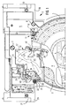
- the figure 1 shows a bearing part 5, which is fastened by means of screws 6, 7, 8 on the drawer 3 and the storage of a spacer plate 9 is used, which can be pivoted for the purpose of changing the underlying diagram disc 2 and with respect to overhead diagram disc is at least partially formed as a registration pad.
- An opening 10 in the bearing part 5 makes the drive connection associated adjusting and entraining 11 visible.
- the registering arrangement 12 is arranged on the opposite side, that is to say on the side of the bearing part 5 facing the overhead diagram disk 1, wherein the bearing part 5 engages between the two diagram disks 1 and 2 and completes the registration substrate for the diagram disk 1.
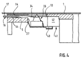
- a formed in the bearing part 5 shallow recess 13 is covered by a plate 14 which by means of rivet joints, one of which is denoted by 15, on the Bearing part 5 is attached. It consists between the unspecified bottom of the recess 13 and the plate 14 is a shallow shaft 16, ( Figure 4), within which a trained according to Figures 2 and 3 writing lever 17 of the registration system is performed.
- the writing lever 17 is mounted on the bearing part 5 outside of a space covered by the diagram disk 1 (bearing point 18). Further, a lever arm 19 is preferably formed by injection molding on the writing lever 17, on which coupling means for driving the writing lever 17, in this case, a toothing 20 are formed. With the toothing 20 is engaged with a gear 21, which is mounted on an attached in the drawer 3 axis 22. With 23 an integrally formed on the lever arm 19 driver is referred to the one leg 24 of a suitable but unspecified manner stored and axially secured leg spring 25 attacks, for the clearance compensation in the geared connection between a not shown, driving servomotor and the writing lever 17 is provided.
- the writing lever 17 carries a writing tip 26, which generally consists of a sapphire needle and its socket.
- the writing tip 26 or its movement path is so that the writing tip 26 can be operative on the back of the diagram disc 1, in the bearing part 5 and in the plate 14 on the one hand as well as in the spacer plate 9 on the other hand assigned suitable recesses 27 and 28.
- FIG. 31 and 32 illustrate conical openings which, in cooperation with suitably formed and spring-mounted pins, serve to fix the drawer in its closed position.
- the writing lever 17 is made of a leaf spring material and is substantially crescent-shaped, that is, on a radial portion 33 of the writing lever 17, which is not rectilinear due to surrounding structures of the bearing part 5, a writing arm 34 corresponding to the trajectory of the writing tip 26th angled formed.
- the one end of the writing lever 17, the writing arm 34 carries the writing tip 26;
- the lever arm 19 and the driver 23 integrally formed as well as a bearing element attached or also formed in shape.
- the illustrated embodiment serves as a bearing element riveted to the writing lever 17 axis 35.
- Adequate would also be the molding of a bearing bush.
- a formed on the driver 23 link 36 serves the leg 24 of the leg spring 25 as a lateral support; the support surface 37 of the leg 24 is rounded to improve the sliding behavior.
- support legs 38, 39 are formed on both sides, which, as already explained in detail in the introduction, in operative connection with the bearing part 5 and the plate 14 are the stiffening of the write lever 17 and the radial portion 33 of the write lever 17 serve.
- the writing arm 34 is bent out of the plane of the radial section 33 of the writing lever 17 to create a bias.
- An integrally formed on the writing arm 34 shoe 40 is used in cooperation with a formed on the bearing part 5 ramp 41 lifting the writing tip 26 of the registration level in the attack area of the Write lever 17, whereby a damage to the chart 1 is avoided during insertion, and without additional parts are required.
- the sliding surface of the ramp 41 is designated.
- An abutment formed on the bearing part 5 wall element 43 cooperates with the driver 23 in the rest position of the registration arrangement 12 as a stop.
- the support leg 39 associated guide surface is designated 44.
- the gear 20 when closing the drawer 3 engages with a fixed gear fixed to the housing, which is for example via an additional gear stage in the power flow with the provided for the drive of the registration assembly 12 servomotor.
- a groove 45 formed in the drawer 3, in cooperation with a bolt fixed to the housing, serves as an advance direction with respect to the engagement of the respective gears of the registration assembly 12 when the drawer 3 is closed.
Landscapes
- Physics & Mathematics (AREA)
- General Physics & Mathematics (AREA)
- Time Recorders, Dirve Recorders, Access Control (AREA)
- Steroid Compounds (AREA)
- Apparatus For Radiation Diagnosis (AREA)
- Coloring Foods And Improving Nutritive Qualities (AREA)
- Pharmaceuticals Containing Other Organic And Inorganic Compounds (AREA)
- Acyclic And Carbocyclic Compounds In Medicinal Compositions (AREA)
Description
- Die Erfindung betrifft eine Registrieranordnung, insbesondere für Fahrtschreiber mit einem drehbar gelagerten Schreibhebel, welcher an seinem einen Ende mit einer in Richtung der Drehachse federnden Schreibspitze versehen ist, welchem ein Lagerelement zugeordnet ist und an welchem Kupplungsmittel für dessen Antrieb befestigt sind.
Bei Fahrtschreibern mit einem vorzugsweise quaderförmigen, flachen Einbaugehäuse und beispielsweise einer dem Wechseln der als Aufzeichnungsträger verwendeten Diagrammscheiben dienenden Schublade bestehen aufgrund der relativ geringen Bauhöhe eines derartigen Gerätes erhebliche Schwierigkeiten hinsichtlich der räumlichen Anordnung der Registriermittel. Dies gilt insbesondere dann, wenn auf einer Diagrammscheibe von beiden Seiten registriert werden soll oder zwei Diagrammscheiben vorgesehen sind, zwischen die Registrierorgane eingreifen und demzufolge diese Registrierorgane in der Schublade angeordnet werden müssen.
Aufgabe der vorliegenden Erfindung war es, eine Registrieranordnung zu schaffen, die sich einerseits baulich für den geschilderten Anwendungsfall eignet und die andererseits den für Fahrtschreiber üblichen Anforderungen hinsichtlich der Großserienfertigung gerecht wird, wobei die Verringerung der Anzahl der Bauteile, gute Reproduzierbarkeit der Bauteile und eine einfache Montage der Registrieranordnung entscheidend sind.
Aus der europäischen Patentanmeldung EP 0 800 151 A2 ist bereits eine Registrieranordnung der eingangs genannten Art bekannt, welche jedoch insbesondere hinsichtlich des Schreibhebels eine in der Höhe raumgreifende Ausbildung vorsieht und insbesondere aufgrund der Bauteilevielfalt einen erhöhten Herstellungsaufwand erfordert . - Das Lösungsprinzip geht aus dem Anspruch 1 hervor. Vorteilhafte Ausgestaltungen der Erfindung sind in den Unteransprüchen beschrieben.
- Die Erkenntnis, daß als Schreibhebel für die zu schaffende Registrieranordnung lediglich ein einziges, beispielsweise aus einem Blattfederwerkstoff ausgestanztes Bauteil vorgesehen werden kann, bietet sowohl eine Bauteilminimierung als auch die Möglichkeit den Schreibhebel innerhalb eines extrem flachen Bauraumes zwischen dem Aufzeichnungsträger, beispielsweise einer Diagrammscheibe, und einem Führungselement eingreifen zu lassen, wobei sich die Lagerstelle des Schreibhebels außerhalb des durch die Diagrammscheibe abgedeckten Bauraumes befindet. Mit anderen Worten, die gefundene Lösung schafft eine Integration zwischen einem federnden Schreibarm und einem starren Schreibhebel mit nur einem Bauteil, das aus einem Blattfederwerkstoff hergestellt und in geeigneter Weise geführt ist. Dabei wird die erforderliche Registrierkraft durch Verbiegen des Schreibhebels an dem stützenden, ortsfesten Führungselement aufgebracht. Das Führungselement kann im einfachsten Falle als Rippe an einer Lagerplatte ausgebildet sein oder es sind an dem Schreibhebel beidseitig Stützschenkel angeformt, die den Schreibhebel auf einer Führungsfläche abstützen.
- Das bevorzugtes Ausführungsbeispiel sieht einen abgewinkelt ausgebildeten Schreibhebel vor, der sich beim Wirksamwerden der Registrierkraft mittels Stützschenkel zwischen zwei führenden Platten federnd abstützt und damit ein Verwinden des radialen Teils des Schreibhebels kompensiert. Auf diese Weise wird einerseits eine spielfreie und reibungsarme Führung sowie eine Versteifung des radialen Teils des Schreibhebels erzielt andererseits läßt sich mit der Länge des abgewinkelten Schreibarmes die Registrierkraft auf einfache Weise und innerhalb eines weiten Bereichs abstimmen. Zweckmäßigerweise ist der abgewinkelte Schreibarm entsprechend dem bogenförmigen Registrierweg der Schreibspitze ebenfalls bogenförmig ausgebildet. Zur Erzielung der Bewegungsfreiheit des Schreibarmes während des Registrierens ist in diesem Falle lediglich eine schmale, der Breite des Schreibarmes entsprechende Freisparung in dem Lagerteil des Schreibhebels erforderlich, was den Raumbedarf der vorgeschlagenen Registrieranordnung auf das kleinstmögliche Maß beschränkt.
- Von Vorteil ist ferner, daß dem Schreibarm in seiner Endstellung eine Rampe zugeordnet ist, die über einen am Schreibarm angeformten Gleitschuh ein Anheben des Schreibstiftes von der Registrierebene bewirkt und die es ermöglicht, daß beim Wechseln des Aufzeichnungsträgers Beschädigungen des Aufzeichnungsträgers durch den Schreibstift vermieden werden.
- Im folgenden wird das bevorzugte Ausführungsbeispiel anhand von Zeichnungen erläutert. Es zeigen:
- Figur 1
- eine Draufsicht auf eine nur teilweise dargestellte Schublade eines Fahrtschreibers mit einem flachen, quaderförmigen Einbaugehäuse, wobei sich die Registrieranordnung in der Ruhestellung befindet,
- Figur 2
- eine vergrößert dargestellte Draufsicht des erfindungsgemäßen Schreibhebels,
- Figur 3
- eine Seitenansicht des Schreibhebels gemäß Figur 2,
- Figur 4
- einen vergrößerten Teilschnitt gemäß der Schnittlinie A in Figur 1.
- Wie aus der Figur 1 hervorgeht, wird die erfindungsgemäße Registrieranordnung in einem Fahrtschreiber verwendet, in dem gleichzeitig auf zwei Diagrammscheiben 1, 2 registriert wird, das heißt, sowohl einem Fahrer als auch einem Beifahrer eine Diagrammscheibe zugeordnet ist. Wird ein solcher Fahrtschreiber als ein beispielsweise einem Autoradio entsprechendes Einbaugerät mit einer die Diagrammscheiben 1, 2 aufnehmenden Schublade 3 konzipiert, so bestehen verständlicherweise erhebliche Schwierigkeiten hinsichtlich der Unterbringung der Antriebsmittel und Antriebsverbindungen zu dem Zentrier- und Mitnahmedorn 4 der Diagrammscheiben 1, 2, der verschiedenen auf den beiden Diagrammscheiben 1, 2 wirksamen Reigstrierorganen sowie den Mitteln zur Verriegelung, Fixierung und Entriegelung der Schublade 3 selbst.
- Im Falle der vorliegenden Erfindung handelt es sich um eine Registrieranordnung, welche für das Aufzeichnen der Drehzahlen des Fahrzeugmotors auf der Rückseite der dem Fahrer zugeordneten Diagrammscheibe 1 vorgesehen ist. Das heißt, ein entsprechendes Registrierorgan muß zwischen die Diagrammscheiben 1, 2 eingreifen und zwischen den Diagrammscheiben 1, 2 wirksam sein, wobei es für die erforderliche Funktion möglichst wenig Bauhöhe beanspruchen sollte.
- Im einzelnen zeigt die Figur 1 ein Lagerteil 5, welches mittels Schrauben 6, 7, 8 auf der Schublade 3 befestigt ist und der Lagerung einer Distanzplatte 9 dient, die zum Zwecke des Wechselns der untenliegenden Diagrammscheibe 2 verschwenkt werden kann und die im Hinblick auf die obenliegende Diagrammscheibe wenigstens teilweise als Registrierunterlage ausgebildet ist. Außerdem trägt die Distanzplatte 9, was, weil nicht erfindungswesentlich, nicht dargestellt ist, an ihrer der Diagrammscheibe 2 zugewandten Seite ein Registrierorgan, dessen Antriebsverbindung an dem Lagerteil 5 gelagert ist. Ein Durchbruch 10 im Lagerteil 5 macht der Antriebsverbindung zugeordnete Justier- und Mitnahmemittel 11 sichtbar.
- Die erfindungsgemäße Registrieranordnung 12 ist an der Gegenseite, das heißt, an der der obenliegenden Diagrammscheibe 1 zugewandten Seite des Lagerteils 5, angeordnet, wobei das Lagerteil 5 zwischen die beiden Diagrammscheiben 1 und 2 eingreift und die gebildete Registrierunterlage für die Diagrammscheibe 1 vervollständigt. Eine in dem Lagerteil 5 ausgebildete flache Vertiefung 13 ist von einer Platte 14 abgedeckt, die mittels Nietverbindungen, von denen eine mit 15 bezeichnet ist, an dem Lagerteil 5 befestigt ist. Dabei besteht zwischen dem nicht näher bezeichneten Boden der Vertiefung 13 und der Platte 14 ein flacher Schacht 16, (Figur 4), innerhalb dessen ein gemäß den Figuren 2 und 3 ausgebildeter Schreibhebel 17 der Registrieranordnung geführt ist. Wie aus der Figur 1 ferner hervorgeht ist der Schreibhebel 17 außerhalb eines durch die Diagrammscheibe 1 abgedeckten Raumes auf dem Lagerteil 5 gelagert (Lagerstelle 18). Ferner ist an dem Schreibhebel 17 ein Hebelarm 19 vorzugsweise spritzgießtechnisch angeformt, an welchem Kupplungsmittel für den Antrieb des Schreibhebels 17, in diesem Falle eine Verzahnung 20 ausgebildet sind. Mit der Verzahnung 20 in Eingriff steht ein Zahnrad 21, welches auf einer in der Schublade 3 befestigten Achse 22 gelagert ist. Mit 23 ist ein an dem Hebelarm 19 angeformter Mitnehmer bezeichnet, an dem der eine Schenkel 24 einer in geeigneter jedoch nicht näher beschriebenen Weise gelagerten und axial gesicherten Schenkelfeder 25 angreift, die für den Spielausgleich in der getrieblichen Verbindung zwischen einem nicht dargestellten, antreibenden Stellmotor und dem Schreibhebel 17 vorgesehen ist. Ferner trägt der Schreibhebel 17 eine im allgemeinen aus einer Saphirnadel und deren Fassung bestehende Schreibspitze 26. Der Schreibspitze 26 bzw. deren Bewegungsweg sind, damit die Schreibspitze 26 an der Rückseite der Diagrammscheibe 1 wirksam sein kann, im Lagerteil 5 und in der Platte 14 einerseits als auch in der Distanzplatte 9 andererseits geeignete Freisparungen 27 und 28 zugeordnet.
- Der Vollständigkeit halber sei bezüglich der Schublade 3 noch erwähnt, daß mit 29 und 30 mit Schlitzen versehene Führungswangen bezeichnet sind, denen im nicht dargestellten Frontbereich der Schublade jeweils fluchtende die Führung ergänzende Wangen zugeordnet sind. 31 und 32 stellen konische Öffnungen dar, die im Zusammenwirken mit in geeigneter Weise ausgebildeten und gefedert gelagerten Zapfen der Fixierung der Schublade in deren Schließstellung dienen.
- Im folgenden sei der Schreibhebel 17 anhand der Figuren 2 und 3 näher erläutert. Der Schreibhebel 17 besteht aus einem Blattfederwerkstoff und ist im wesentlichen sichelförmig ausgebildet, das heißt, an einem radialen Teilstück 33 des Schreibhebels 17, welches aufgrund von zu umgehenden Strukturen des Lagerteils 5 nicht geradlinig ausgebildet ist, ist ein Schreibarm 34 entsprechend der Bewegungsbahn der Schreibspitze 26 abgewinkelt angeformt. Das eine Ende des Schreibhebels 17, der Schreibarm 34, trägt die Schreibspitze 26; an dem anderen Ende sind, unter Vorsehung geeigneter, stabilisierende Randverstärkungen, der Hebelarm 19 und der Mitnehmer 23 einteilig angeformt sowie ein Lagerelement befestigt bzw. ebenfalls formtechnisch ausgebildet. Im Falle des dargestellten Ausführungsbeispiels dient als Lagerelement eine mit dem Schreibhebel 17 vernietete Achse 35. Zweckentsprechend wäre auch das Anformen einer Lagerbuchse. Eine an dem Mitnehmer 23 ausgeformte Kulisse 36 dient dem Schenkel 24 der Schenkelfeder 25 als seitliche Halterung; die Auflagefläche 37 des Schenkels 24 ist zur Verbesserung des Gleitverhaltens gerundet ausgebildet. An dem radialen Teilstück 33 des Schreibhebels 17 sind beidseitig Stützschenkel 38, 39 ausgebildet, die, wie bereits ausführlich in der Beschreibungseinleitung erläutert, in Wirkverbindung mit dem Lagerteil 5 und der Platte 14 stehen der Versteifung des Schreibhebels 17 bzw. des radialen Teilstücks 33 des Schreibhebels 17 dienen. Mit anderen Worten, durch Verschwenken des Schreibarmes 34 in Achsrichtung des Schreibhebels 17, das heißt, durch Aufbringen der erforderlichen Registrierkraft wird in das radiale Teilstück 33 des Schreibhebels 17 ein Drehmoment eingeleitet, welches durch die Stützschenkel 38, 39 kompensiert und dadurch ein Verkanten des Schreibhebels 17 vermieden wird. Wie außerdem den Figuren 2 und 3 noch entnommen werden kann, ist der Schreibarm 34 zur Schaffung einer Vorspannung aus der Ebene des radialen Teilstücks 33 des Schreibhebels 17 herausgebogen. Ein an dem Schreibarm 34 angeformter Gleitschuh 40 dient im Zusammenwirken mit einer an dem Lagerteil 5 ausgebildeten Rampe 41 dem Abheben der Schreibspitze 26 von der Registrierebene im Anschlagbereich des Schreibhebels 17, womit ein Beschädigen der Diagrammscheibe 1 beim Einlegen vermieden ist, und zwar, ohne daß zusätzliche Teile erforderlich sind. Mit 42 ist in Figur 4 die Aufgleitfläche der Rampe 41 bezeichnet. Als Anschlag dient ein am Lagerteil 5 ausgebildetes Wandelement 43 mit dem der Mitnehmer 23 in der Ruhestellung der Registrieranordnung 12 zusammenwirkt. Die dem Stützschenkel 39 zugeordnete Führungsfläche ist mit 44 bezeichnet.
- Schließlich sei noch erwähnt, daß das Zahnrad 20 beim Schließen der Schublade 3 in Eingriff kommt mit einem gehäusefest gelagerten Zahnrad, welches beispielsweise über eine zusätzliche Getriebestufe im Kraftfluß mit dem für den Antrieb der Registrieranordnung 12 vorgesehenen Stellmotor steht. Eine in der Schublade 3 ausgebildete Nut 45 dient im Zusammenwirken mit einem gehäusefest angeordneten Bolzen als Vorausrichtung bezüglich des Ineingriffbringens der betreffenden Zahnräder der Registrieranordnung 12 beim Schließen der Schublade 3.
Claims (8)
- Registrieranordnung, insbesondere für Fahrtschreiber mit einem drehbar gelagerten Schreibhebel, welcher an seinem einen Ende mit einer in Richtung der Drehachse federnden Schreibspitze versehen ist, welchem ein Lagerelement zugeordnet ist und an welchem Kupplungsmittel für dessen Antrieb befestigt sind,
dadurch gekennzeichnet,
daß der Schreibhebel (17) als ein im wesentlichen in sich federndes, flaches Bauteil ausgebildet ist und das Lagerelement (35) und die Kupplungsmittel (19, 20) an dem der Schreibspitze (26) entgegengesetzten Ende des Schreibhebels (17) angeordnet sind und
daß dem Schreibhebel (17) ein in einer zu dessen Bewegungsebene parallelen Ebene angeordnetes Führungselement zugeordnet ist, auf dem sich der Schreibhebel (17) wenigstens während des Registrierens abstützt. - Registrieranordnung nach Anspruch 1,
dadurch gekennzeichnet,
daß an dem Schreibhebel (17) wenigstens ein in Bewegungsrichtung des Schreibhebels (17) sich erstreckender und mit dem Führungselement zusammenwirkender Stützschenkel (39) angeformt ist. - Registrieranordnung nach Anspruch 1,
dadurch gekennzeichnet,
daß der Schreibhebel (17) aus einem Blattfederwerkstoff hergestellt ist. - Registrieranordnung nach Anspruch 1,
dadurch gekennzeichnet,
daß dem Schreibhebel (17) eine Rückstellfeder zugeordnet ist. - Registrieranordnung nach Anspruch 4,
dadurch gekennzeichnet,
daß als Rückstellfeder eine Schenkelfeder (25) vorgesehen ist und
daß dem einen Schenkel (24) der Schenkelfeder (25) eine in einem an dem Schreibhebel (17) angeformten Mitnehmer (23) ausgebildete Kulisse (36) zugeordnet ist. - Registrieranordnung nach Anspruch 1,
dadurch gekennzeichnet,
daß dem Schreibhebel (17) eine dem Anheben des Schreibstiftes (26) von der Registrierebene dienende Rampe (41) derart zugeordnet ist, daß die Rampe (41) bezogen auf das Führungselement (5) in die entgegengesetzte Richtung weist und
daß an dem Schreibhebel (17) ein mit der Rampe (41) zusammenwirkender Gleitschuh (40) angeformt ist. - Registrieranordnung nach Anspruch 1,
dadurch gekennzeichnet,
daß bei Verwendung eines Schreibhebels (17) mit einem abgewinkelt ausgebildeten Schreibarm (34) beiderseits des im wesentlichen radialen Teilstücks (33) des Schreibhebels (17) Stützschenkel (38, 39) angeformt sind, wobei der eine Stützschenkel einem in einer Parallellage zum ersten Führungselement angeordneten zweiten Führungselement zugeordnet ist und sich das zweite Führungselement auf der dem ersten Führungselement entgegengesetzten Seite des Schreibhebels (17) befindet. - Registrieranordnung nach Anspruch 6,
dadurch gekennzeichnet,
daß ein Lagerteil (5) vorgesehen ist mit wenigstens einer Lagerung für den Schreibhebel (17), einer als Führungselement dienenden Führungsfläche (44) für den einen Stützschenkel (39), Mitteln zum Befestigen einer das zweite Führungselement bildenden Platte (14) und einer Freisparung (27), welche ein Eintauchen des abgewinkelten Schreibarmes (34) in die Ebene der Führungsfläche (44) ermöglicht.
Applications Claiming Priority (2)
| Application Number | Priority Date | Filing Date | Title |
|---|---|---|---|
| DE29901615U | 1999-01-30 | ||
| DE29901615U DE29901615U1 (de) | 1999-01-30 | 1999-01-30 | Registrieranordnung, insbesondere für Fahrtschreiber |
Publications (2)
| Publication Number | Publication Date |
|---|---|
| EP1024349A1 EP1024349A1 (de) | 2000-08-02 |
| EP1024349B1 true EP1024349B1 (de) | 2007-03-07 |
Family
ID=8068701
Family Applications (1)
| Application Number | Title | Priority Date | Filing Date |
|---|---|---|---|
| EP00101135A Expired - Lifetime EP1024349B1 (de) | 1999-01-30 | 2000-01-21 | Registrieranordnung, insbesondere für Fahrtschreiber |
Country Status (5)
| Country | Link |
|---|---|
| EP (1) | EP1024349B1 (de) |
| AT (1) | ATE356339T1 (de) |
| DE (2) | DE29901615U1 (de) |
| DK (1) | DK1024349T3 (de) |
| ES (1) | ES2278553T3 (de) |
Family Cites Families (1)
| Publication number | Priority date | Publication date | Assignee | Title |
|---|---|---|---|---|
| DE19613872A1 (de) * | 1996-04-06 | 1997-10-09 | Vdo Schindling | Antriebsverbindung für ein Registrierorgan in einem Fahrtschreiber |
-
1999
- 1999-01-30 DE DE29901615U patent/DE29901615U1/de not_active Expired - Lifetime
-
2000
- 2000-01-21 ES ES00101135T patent/ES2278553T3/es not_active Expired - Lifetime
- 2000-01-21 DE DE50014125T patent/DE50014125D1/de not_active Expired - Lifetime
- 2000-01-21 EP EP00101135A patent/EP1024349B1/de not_active Expired - Lifetime
- 2000-01-21 DK DK00101135T patent/DK1024349T3/da active
- 2000-01-21 AT AT00101135T patent/ATE356339T1/de active
Also Published As
| Publication number | Publication date |
|---|---|
| ES2278553T3 (es) | 2007-08-16 |
| DE50014125D1 (de) | 2007-04-19 |
| ATE356339T1 (de) | 2007-03-15 |
| DE29901615U1 (de) | 1999-04-08 |
| EP1024349A1 (de) | 2000-08-02 |
| DK1024349T3 (da) | 2007-07-02 |
Similar Documents
| Publication | Publication Date | Title |
|---|---|---|
| DE69605555T2 (de) | Speicherplatteneinheit montagevorrichtung | |
| EP0879754A1 (de) | Vorrichtung zum Einstellen der Spur bei Rädern von Kraftfahrzeugen | |
| EP0169363B1 (de) | Vorrichtung, insbesondere Hubwischeranlage für Kraftfahrzeuge | |
| DE102008042281A1 (de) | Wellenlagerung in einem Lenksystem und damit ausgestattetes Lenkgetriebe sowie Verfahren zur Herstellung einer Halterung dafür | |
| DE69824079T2 (de) | Laufwerk mit Plattenteller | |
| EP0864137B1 (de) | Fahrtschreiber mit einer schublade | |
| EP1184667B1 (de) | Fahrtschreiber mit zwei in einer Ebene angeordneten Lese-/Schreibaggregaten für Datenkarten | |
| DE19613872A1 (de) | Antriebsverbindung für ein Registrierorgan in einem Fahrtschreiber | |
| EP1024349A1 (de) | Registrieranordnung, insbesondere für Fahrtschreiber | |
| DE4438926A1 (de) | Anordnung der Aufzeichnungsträger in einem Fahrtschreiber mit einem flachen Einbaugehäuse | |
| DE69800074T2 (de) | Befestigungsvorrichtung für Schlittenantriebsmotor und damit ausgerüsteter Gleitzuführvorrichtung | |
| DE3635920C1 (en) | Motor-driven adjustment device of a vehicle rearview mirror | |
| EP1943712A1 (de) | Elektromotor mit befestigungsadapter | |
| DE60012631T2 (de) | Klemmvorrichtung für Diskettenlaufwerk | |
| EP1863990B1 (de) | Treibstangenantrieb | |
| DE19755310C2 (de) | Anordnung zum Festspannen einer Diagrammscheibe | |
| DE19756712B4 (de) | Mittel zum Festhalten eines dem Festspannen von Diagrammscheiben in einem Fahrtschreiber dienenden Spannelementes in einer Mitnahmeposition | |
| EP1736363B1 (de) | Montageanordnung zur Montage eines Einbaugerätes in einem Kraftfahrzeug | |
| DE19546029C2 (de) | Fahrtschreiber mit einem Schreibsystem für Geschwindigkeitsaufzeichnungen | |
| DE69421879T2 (de) | Plattenantriebsgerät mit Plattenteller mit Halterung | |
| EP1132740B1 (de) | Halter für ein Trennmesser und Vorkehrungen zum Befestigen des Halters in einem Fahrtschreiber | |
| EP1189177B1 (de) | Diagrammscheibenträger für einen Fahrtschreiber | |
| EP0935220A2 (de) | Fahrtschreiber mit einem quaderförmigen Gehäuse | |
| DE19750683B4 (de) | Justiervorrichtung für die Antriebsverbindung eines Balkendiagramme aufzeichnenden Registrierorgans | |
| DE29701586U1 (de) | Anordnung zum Festspannen von Diagrammscheiben |
Legal Events
| Date | Code | Title | Description |
|---|---|---|---|
| PUAI | Public reference made under article 153(3) epc to a published international application that has entered the european phase |
Free format text: ORIGINAL CODE: 0009012 |
|
| AK | Designated contracting states |
Kind code of ref document: A1 Designated state(s): AT BE CH CY DE DK ES FI FR GB GR IE IT LI LU MC NL PT SE |
|
| AX | Request for extension of the european patent |
Free format text: AL;LT;LV;MK;RO;SI |
|
| 17P | Request for examination filed |
Effective date: 20001109 |
|
| AKX | Designation fees paid |
Free format text: AT BE CH CY DE DK ES FI FR GB GR IE IT LI LU MC NL PT SE |
|
| RAP1 | Party data changed (applicant data changed or rights of an application transferred) |
Owner name: SIEMENS AKTIENGESELLSCHAFT |
|
| 17Q | First examination report despatched |
Effective date: 20041129 |
|
| GRAP | Despatch of communication of intention to grant a patent |
Free format text: ORIGINAL CODE: EPIDOSNIGR1 |
|
| GRAS | Grant fee paid |
Free format text: ORIGINAL CODE: EPIDOSNIGR3 |
|
| GRAA | (expected) grant |
Free format text: ORIGINAL CODE: 0009210 |
|
| AK | Designated contracting states |
Kind code of ref document: B1 Designated state(s): AT BE CH CY DE DK ES FI FR GB GR IE IT LI LU MC NL PT SE |
|
| PG25 | Lapsed in a contracting state [announced via postgrant information from national office to epo] |
Ref country code: FI Free format text: LAPSE BECAUSE OF FAILURE TO SUBMIT A TRANSLATION OF THE DESCRIPTION OR TO PAY THE FEE WITHIN THE PRESCRIBED TIME-LIMIT Effective date: 20070307 Ref country code: IE Free format text: LAPSE BECAUSE OF FAILURE TO SUBMIT A TRANSLATION OF THE DESCRIPTION OR TO PAY THE FEE WITHIN THE PRESCRIBED TIME-LIMIT Effective date: 20070307 |
|
| REG | Reference to a national code |
Ref country code: GB Ref legal event code: FG4D Free format text: NOT ENGLISH |
|
| REG | Reference to a national code |
Ref country code: CH Ref legal event code: EP |
|
| REF | Corresponds to: |
Ref document number: 50014125 Country of ref document: DE Date of ref document: 20070419 Kind code of ref document: P |
|
| REG | Reference to a national code |
Ref country code: IE Ref legal event code: FG4D Free format text: LANGUAGE OF EP DOCUMENT: GERMAN |
|
| GBT | Gb: translation of ep patent filed (gb section 77(6)(a)/1977) |
Effective date: 20070524 |
|
| REG | Reference to a national code |
Ref country code: SE Ref legal event code: TRGR |
|
| REG | Reference to a national code |
Ref country code: DK Ref legal event code: T3 |
|
| ET | Fr: translation filed | ||
| PG25 | Lapsed in a contracting state [announced via postgrant information from national office to epo] |
Ref country code: PT Free format text: LAPSE BECAUSE OF FAILURE TO SUBMIT A TRANSLATION OF THE DESCRIPTION OR TO PAY THE FEE WITHIN THE PRESCRIBED TIME-LIMIT Effective date: 20070807 |
|
| REG | Reference to a national code |
Ref country code: ES Ref legal event code: FG2A Ref document number: 2278553 Country of ref document: ES Kind code of ref document: T3 |
|
| REG | Reference to a national code |
Ref country code: IE Ref legal event code: FD4D |
|
| PLBE | No opposition filed within time limit |
Free format text: ORIGINAL CODE: 0009261 |
|
| STAA | Information on the status of an ep patent application or granted ep patent |
Free format text: STATUS: NO OPPOSITION FILED WITHIN TIME LIMIT |
|
| 26N | No opposition filed |
Effective date: 20071210 |
|
| PG25 | Lapsed in a contracting state [announced via postgrant information from national office to epo] |
Ref country code: GR Free format text: LAPSE BECAUSE OF FAILURE TO SUBMIT A TRANSLATION OF THE DESCRIPTION OR TO PAY THE FEE WITHIN THE PRESCRIBED TIME-LIMIT Effective date: 20070608 |
|
| PG25 | Lapsed in a contracting state [announced via postgrant information from national office to epo] |
Ref country code: MC Free format text: LAPSE BECAUSE OF NON-PAYMENT OF DUE FEES Effective date: 20080131 |
|
| REG | Reference to a national code |
Ref country code: CH Ref legal event code: PL |
|
| PG25 | Lapsed in a contracting state [announced via postgrant information from national office to epo] |
Ref country code: CH Free format text: LAPSE BECAUSE OF NON-PAYMENT OF DUE FEES Effective date: 20080131 Ref country code: LI Free format text: LAPSE BECAUSE OF NON-PAYMENT OF DUE FEES Effective date: 20080131 |
|
| PGFP | Annual fee paid to national office [announced via postgrant information from national office to epo] |
Ref country code: DK Payment date: 20090113 Year of fee payment: 10 Ref country code: ES Payment date: 20090122 Year of fee payment: 10 |
|
| PG25 | Lapsed in a contracting state [announced via postgrant information from national office to epo] |
Ref country code: CY Free format text: LAPSE BECAUSE OF FAILURE TO SUBMIT A TRANSLATION OF THE DESCRIPTION OR TO PAY THE FEE WITHIN THE PRESCRIBED TIME-LIMIT Effective date: 20070307 |
|
| PGFP | Annual fee paid to national office [announced via postgrant information from national office to epo] |
Ref country code: BE Payment date: 20090219 Year of fee payment: 10 |
|
| PGFP | Annual fee paid to national office [announced via postgrant information from national office to epo] |
Ref country code: IT Payment date: 20100125 Year of fee payment: 11 |
|
| PG25 | Lapsed in a contracting state [announced via postgrant information from national office to epo] |
Ref country code: LU Free format text: LAPSE BECAUSE OF NON-PAYMENT OF DUE FEES Effective date: 20080121 |
|
| BERE | Be: lapsed |
Owner name: SIEMENS A.G. Effective date: 20100131 |
|
| REG | Reference to a national code |
Ref country code: DK Ref legal event code: EBP |
|
| REG | Reference to a national code |
Ref country code: NL Ref legal event code: SD Effective date: 20101130 Ref country code: NL Ref legal event code: TD Effective date: 20101130 |
|
| PG25 | Lapsed in a contracting state [announced via postgrant information from national office to epo] |
Ref country code: DK Free format text: LAPSE BECAUSE OF NON-PAYMENT OF DUE FEES Effective date: 20100131 |
|
| PG25 | Lapsed in a contracting state [announced via postgrant information from national office to epo] |
Ref country code: BE Free format text: LAPSE BECAUSE OF NON-PAYMENT OF DUE FEES Effective date: 20100131 |
|
| REG | Reference to a national code |
Ref country code: ES Ref legal event code: FD2A Effective date: 20110412 |
|
| REG | Reference to a national code |
Ref country code: FR Ref legal event code: TP |
|
| PG25 | Lapsed in a contracting state [announced via postgrant information from national office to epo] |
Ref country code: ES Free format text: LAPSE BECAUSE OF NON-PAYMENT OF DUE FEES Effective date: 20110331 |
|
| REG | Reference to a national code |
Ref country code: GB Ref legal event code: 732E Free format text: REGISTERED BETWEEN 20110825 AND 20110831 |
|
| PG25 | Lapsed in a contracting state [announced via postgrant information from national office to epo] |
Ref country code: ES Free format text: LAPSE BECAUSE OF NON-PAYMENT OF DUE FEES Effective date: 20100122 |
|
| PG25 | Lapsed in a contracting state [announced via postgrant information from national office to epo] |
Ref country code: IT Free format text: LAPSE BECAUSE OF NON-PAYMENT OF DUE FEES Effective date: 20110121 |
|
| PGFP | Annual fee paid to national office [announced via postgrant information from national office to epo] |
Ref country code: GB Payment date: 20130122 Year of fee payment: 14 Ref country code: SE Payment date: 20130122 Year of fee payment: 14 Ref country code: FR Payment date: 20130213 Year of fee payment: 14 |
|
| PGFP | Annual fee paid to national office [announced via postgrant information from national office to epo] |
Ref country code: NL Payment date: 20130122 Year of fee payment: 14 |
|
| PGFP | Annual fee paid to national office [announced via postgrant information from national office to epo] |
Ref country code: AT Payment date: 20130111 Year of fee payment: 14 |
|
| REG | Reference to a national code |
Ref country code: NL Ref legal event code: V1 Effective date: 20140801 |
|
| REG | Reference to a national code |
Ref country code: AT Ref legal event code: MM01 Ref document number: 356339 Country of ref document: AT Kind code of ref document: T Effective date: 20140121 |
|
| REG | Reference to a national code |
Ref country code: SE Ref legal event code: EUG |
|
| GBPC | Gb: european patent ceased through non-payment of renewal fee |
Effective date: 20140121 |
|
| PG25 | Lapsed in a contracting state [announced via postgrant information from national office to epo] |
Ref country code: NL Free format text: LAPSE BECAUSE OF NON-PAYMENT OF DUE FEES Effective date: 20140801 |
|
| REG | Reference to a national code |
Ref country code: FR Ref legal event code: ST Effective date: 20140930 |
|
| PG25 | Lapsed in a contracting state [announced via postgrant information from national office to epo] |
Ref country code: SE Free format text: LAPSE BECAUSE OF NON-PAYMENT OF DUE FEES Effective date: 20140122 Ref country code: AT Free format text: LAPSE BECAUSE OF NON-PAYMENT OF DUE FEES Effective date: 20140121 Ref country code: FR Free format text: LAPSE BECAUSE OF NON-PAYMENT OF DUE FEES Effective date: 20140131 Ref country code: GB Free format text: LAPSE BECAUSE OF NON-PAYMENT OF DUE FEES Effective date: 20140121 |
|
| PGFP | Annual fee paid to national office [announced via postgrant information from national office to epo] |
Ref country code: DE Payment date: 20150131 Year of fee payment: 16 |
|
| REG | Reference to a national code |
Ref country code: DE Ref legal event code: R119 Ref document number: 50014125 Country of ref document: DE |
|
| PG25 | Lapsed in a contracting state [announced via postgrant information from national office to epo] |
Ref country code: DE Free format text: LAPSE BECAUSE OF NON-PAYMENT OF DUE FEES Effective date: 20160802 |