EP0243383B1 - Installation de repos, notamment pour lit - Google Patents
Installation de repos, notamment pour lit Download PDFInfo
- Publication number
- EP0243383B1 EP0243383B1 EP86905711A EP86905711A EP0243383B1 EP 0243383 B1 EP0243383 B1 EP 0243383B1 EP 86905711 A EP86905711 A EP 86905711A EP 86905711 A EP86905711 A EP 86905711A EP 0243383 B1 EP0243383 B1 EP 0243383B1
- Authority
- EP
- European Patent Office
- Prior art keywords
- reclining
- longitudinal members
- lying
- means according
- covering
- Prior art date
- Legal status (The legal status is an assumption and is not a legal conclusion. Google has not performed a legal analysis and makes no representation as to the accuracy of the status listed.)
- Expired - Lifetime
Links
Images

Classifications
-
- A—HUMAN NECESSITIES
- A47—FURNITURE; DOMESTIC ARTICLES OR APPLIANCES; COFFEE MILLS; SPICE MILLS; SUCTION CLEANERS IN GENERAL
- A47C—CHAIRS; SOFAS; BEDS
- A47C23/00—Spring mattresses with rigid frame or forming part of the bedstead, e.g. box springs; Divan bases; Slatted bed bases
- A47C23/06—Spring mattresses with rigid frame or forming part of the bedstead, e.g. box springs; Divan bases; Slatted bed bases using wooden springs, e.g. of slat type ; Slatted bed bases
- A47C23/062—Slat supports
- A47C23/063—Slat supports by elastic means, e.g. coil springs
-
- A—HUMAN NECESSITIES
- A47—FURNITURE; DOMESTIC ARTICLES OR APPLIANCES; COFFEE MILLS; SPICE MILLS; SUCTION CLEANERS IN GENERAL
- A47C—CHAIRS; SOFAS; BEDS
- A47C23/00—Spring mattresses with rigid frame or forming part of the bedstead, e.g. box springs; Divan bases; Slatted bed bases
- A47C23/06—Spring mattresses with rigid frame or forming part of the bedstead, e.g. box springs; Divan bases; Slatted bed bases using wooden springs, e.g. of slat type ; Slatted bed bases
-
- A—HUMAN NECESSITIES
- A47—FURNITURE; DOMESTIC ARTICLES OR APPLIANCES; COFFEE MILLS; SPICE MILLS; SUCTION CLEANERS IN GENERAL
- A47C—CHAIRS; SOFAS; BEDS
- A47C23/00—Spring mattresses with rigid frame or forming part of the bedstead, e.g. box springs; Divan bases; Slatted bed bases
- A47C23/30—Spring mattresses with rigid frame or forming part of the bedstead, e.g. box springs; Divan bases; Slatted bed bases using combinations of springs covered by more than one of the groups A47C23/04, A47C23/06 and A47C23/12; Frames therefor
Definitions
- the invention relates to a resting and lying device according to the preamble of the independent claim.
- the current state of the art in slatted frame battens is designed to flexibly support resilient cross slats, the individual slat forming the main spring element.
- the crossbar claimed as the main spring element usually has a complicated multilayer gluing in order to realize the so-called cant (arch).
- the elevation serves to ensure that the individual spring slats are bent straight in the event of a load and thus the lying surface becomes "flat”.
- This load-dependent Leige "level” is matched to the load of an average (usually 170 cm tall and 70 kg heavy) people.
- the known slatted frame beds are still relatively solid and heavy constructions with a large number of individual elements such as position stabilizers of the slats, usually arranged in the center, terminal flex elements and their attachment to the slat and frame (these constructions require a frame) and in a kind of refinement with additional battens and special battens, all mostly in distinctive colors and more.
- DE-A-2 949 348 takes a somewhat different approach, in which a mattress base is designed in such a way that an upper frame with a slatted frame rests on elastic elements, which in turn are carried by a lower frame. Thanks to the elastic elements, a more or less flexible support of the upper frame is achieved, but the entire construction is - due to the two fixed connections and consequently rigid frame - relatively cumbersome (e.g. during transport, moving). In addition, there is a spring effect only with respect to the entire upper frame, but not with respect to the individual crossbars of the upper frame that support the mattress.
- EP-A-0 116 237 which consists only of two inflatable longitudinal spars, each of which has a row of pockets oriented transversely to the longitudinal direction on its upper side, so that a number of transverse battens, the ends of each in a pocket of the parallel longitudinal spars are inserted, a rust-like structure is created.
- it is a construction that is more suitable for temporary use, since stability is hardly guaranteed over a long period of use. Since the cot is only held together by the crossbars in the pockets, there is a risk that the crossbars will exist even with low horizontal forces between the two longitudinal spars (e.g. when moving, carrying around, or even if they are only exposed to the intended use) slide out of your pockets and the reclining device breaks down into its individual components. Since the pockets tend to expand when used, the stability of this device decreases with age.
- the invention is therefore based on the object of creating a resting and lying device of the type mentioned at the outset and developing it in such a way that the various requirements mentioned above (criteria a, b, c) are ensured in a simple and economical manner together with a controllable spring action.
- the lying plane With the lying plane according to the invention, a uniform suspension which can be adapted to the different human bodies is ensured over the entire surface, ie the lying plane functions together with the human body independently of the mattress.
- the suspension is essentially due to the elasticity of the longitudinally extending support elements (Lähgspolme, spring body) and not defined by the slatted elements lying in a rust-like arrangement and is preferably adapted to the weight of the respective user by the spring body.
- the lying surface remains flat and is only perceived as too hard or too soft.
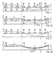
- Figures 1 and 2 branch in a stylized representation of a functional example of a slatted bed surface according to the prior art, compared to one according to the invention. They show the fundamental difference in spring dynamics, how it can come about through the invention on the one hand and how it is common today on the other hand.
- Both stylized slatted bed surfaces of Figures 1 and 2 have as primary elements a longitudinal spar 1, which in the prior art can also be a rigid bed frame between which the slats are attached, and crossbars connected to the longitudinal spar. Both structures have a stress curve B superimposed on them, drawn in and both structures react in their characteristic way with a stress profile or a lying curve L.
- Figure 1 shows the lying surface with a rigid longitudinal beam 1, a slat suspension with crossbars 2 in a list 20 to 27 and with slats 3 in the list 30 to 37, which perform their usual spring task in the longitudinal direction.
- the dashed stress curve B is chosen so that the elastic adaptation of the structure is heavily stressed.
- Figure 1A shows the reaction to this load case.
- the slats 30, 31, 32 are evenly lightly loaded and the spring elements 20, 21, 22 hardly show any deformation.
- the slat 33 is loaded obliquely and the spring element 23 is deformed on one side.
- the spring elements are pushed all the way through, the resulting lying curve being distorted in the area of the spring elements in relation to the load curve.
- FIG. 2A It is quite different with the bed according to the invention in FIG. 2.
- the primary elements are supported on a solid (non-resilient) base 4, for example on the floor.
- These are elastic longitudinal spars 1 (spring body) with resting slats 3 supported thereon, which are generally straight, that is to say they have no functional bend and do not have to perform any special spring function in their longitudinal direction when loaded.
- the entire suspension task is thus transferred to the elastic longitudinal bars (spring body).
- the same load curve B as already shown in FIG. 1A, is also shown superimposed here. The effect of this load case is shown in Figure 2A.
- the lying curve L coincides with the load curve B over the entire width of the bed, which means that there is no distortion in the outer or edge area and there is therefore no significant suspension deficit D.
- the construction according to the invention is therefore able to adapt better to an anatomical load profile .
- the above-mentioned orthopedic teaching is fulfilled in that the elasticity of the longitudinal spars (spring body) corresponds to the weight of the user is chosen speaking. If a material that is too soft is used, there is still no sagging in the longitudinal direction, since the spring stroke is limited by the fixed base 4, which itself does not spring. If a material that is too hard is used, the user is still not too high because no pre-stressed crossbars are used.
- the lying surface is only perceived as somewhat hard. In embodiments described later, these can be easily adapted.
- the anatomical load profile is significantly more important in the longitudinal direction than in the transverse direction. So far, if greater efforts have been made to construct slatted bed frames mainly in the transverse direction than in the longitudinal direction, this was due to the general development of this type of bed. The first efforts were aimed only at the springy effect of the then rigid slats, which were only later flexibly attached. Since then, there has been no fundamental change, despite the constant effort to achieve as much spring comfort as possible in the longitudinal direction.
- the lead surface construction according to the inventive idea allows unusually light and, in addition, simple embodiments.
- such beds can be placed directly on the floor or in a conventional manner in a bed frame.
- This allows a variety of uses, for example, as a camping bed, as an emergency bed, as a normal bed, as a wall bed, etc., without sacrificing quality of lying comfort, which is quite remarkable in the price range of a camping bed. If you consider that all of the above-mentioned applications each have their own design and there are enormous differences in quality, the bedding, which brings all this down to a common denominator, is a very advanced concept.
- FIG. 3 shows the essential parts of a document structure, designated in its entirety by 10, in a sectional view and in FIG. 4 in a side view.
- the underlay structure 10 comprises at least two longitudinal spars (spring bodies) 12, 12 ', or 1 according to FIGS. 2, 2A, which are arranged at a parallel spacing from one another and run in the longitudinal direction of the underlay structure, on which a plurality of transverse battens 13 which are essentially oriented transversely thereto are arranged.
- the individual transverse slats 13 arranged at a distance from one another form a slatted frame designated as a whole by 14.
- the fixed, non-resilient base 4 designated according to FIGS. 2, 2A is referred to as support spars.
- the document structure 10 'shown in FIG. 5 largely corresponds to the document structure 10 described above with reference to FIGS. 3, 4.
- three longitudinal spars (spring bodies) 12, 12', 12 "arranged at a distance from one another are provided, for example. for a double bed or when using softer material for the longitudinal spars 12 (spring body).
- the approximately regularly spaced transverse slats 13 are operatively connected to the longitudinal spars (spring bodies) 12, 12 ', 12 "in a manner not shown in detail and together form essentially a structural unit which, in accordance with the longitudinal spars (spring bodies) 12, 12', 12 "assigned carriers 11, 11 ', 11" of a bed box or bed frame, not shown, or lie on the floor.
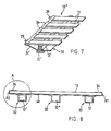
- FIG. 6 shows a base structure 20 which comprises two or more integrated longitudinal spars (spring bodies) 22, 22 ', 22 "which are arranged at a distance from one another, a large number of transverse slats 23 and a film-like beam 25.
- the beam 25 essentially consists of a central part 25 'connecting the support elements 22, 22' and two side parts 21, 21 '.
- the side parts 21, 21' are provided with pockets 24, 24 'arranged at a distance from one another in the longitudinal direction of the underlay structure 20, which are designed to receive the crossbars 23.
- a film-like cover 28 (dashed line) covering the crossbars 23 can be provided, which in the area of the pockets 24, 24 'has a total length of the underlay structure 20 running zipper (not shown) is connected to the beam 25.
- a light top mattress preferably a futon (Japanese bed), not shown here, can be placed loosely on the slatted frame 14.
- a futon Japanese bed
- such a mattress is much cheaper than a mattress in the traditional sense.
- FIG. 6A shows a modified embodiment based on FIG. 5, in which the cover 28 is stretched only over a medium-length, spring-acting longitudinal bar (spring body) 12 ", while the two outer, laterally running, spring-acting longitudinal bars (spring body) 12
- outer longitudinal spars spring bodies
- FIG. 7 shows a part of a document structure 10 "in a perspective top view.
- This document structure 10" essentially corresponds with the parts 11 ', 12', 13 of the document structure 10 and 10 'according to FIGS. 3, 4 and 5.
- This in this exemplary embodiment has a share spaced pockets.
- the Darge in Fig. 7 The partial section shows one side of the underlay structure 10 "and the side part 31 'with the pockets 34' can be seen, in which the crossbars 13 are inserted and held in a form-fitting manner trained (not shown).
- FIG. 8 shows, as a further embodiment, a type of clothing that differs from that shown in FIGS. 6 and 7 and that goes beyond that of FIG. 6A.
- the underlay structure is formed by a plurality, preferably two or three, of integrated longitudinal bars (spring bodies) 12, 12 ', 12 ", a plurality of transverse slats 13 and a covering 40.
- the covering with the aforementioned pockets 24, 34 now runs completely along the crossbars 13; the longitudinal support elements 12, 12 ', 12 "are inserted into tunnel strips 32 sewn onto the covering, details of which will be discussed in connection with FIG. 9.
- the covering 40 runs relatively well in the crossbar direction so that the battens remain in their assigned pockets (FIGS. 6, 7, 8) in every load case.
- the crossbars 13 normally do not bend.
- the slats are preferably made of non-glued solid wood, are 8-12 mm thick, have no cant and are therefore easy to manufacture. These slats are deflected at most under extreme point loads, for example when standing or jumping on such a structure. In this case, it may happen that a crossbar slips out of its pocket holder, but it is very easy to put it back into its holder, for example with the help of a shoehorn.
- the longitudinal spars (spring bodies) 1, 12, 12 ', 12 "and 22, 22' shown in the figures are basically designed as resilient molded parts.
- longitudinal spars (spring body) 12, 12 ', 12 "have full profile cross-section and are made of elastic material, for example latex foam, cellular rubber, foams or the like with polygonal, cuboid, circular or elliptical A square cross-section of 50-70 mm is recommended for children's beds, and 70-100 mm for adult beds, in order to ensure the full spring stroke required.
- Preferred materials are soft materials, especially soft-foamed latex, so that the longitudinal spars can be pulled through adjust the dead weight of the lying surface to a predetermined contour of the rigid surface 4, 11.
- the longitudinal spars (spring bodies) 22, 22 'shown in FIG. 6 are designed as a tubular hollow body and can have a cuboid, circular or elliptical profile cross section. These longitudinal spars (spring bodies) are designed as inflatable hollow bodies, on which the side parts 21, 21 'and the central part 25' of the beam 25 are molded or welded.
- the individual, slat-like transverse slats 13 in their entirety form the slatted frame designated by 14.
- the single crossbar 13 is preferably made of non-glued solid wood. Layer-glued Fournier wood, plastic with a suitable shape, extrudal profiles or relatively thin steel sheet or the like can be used as the further material for the production of the crossbars 13.
- the distance between the individual crossbars 13 is preferably in the order of magnitude of 10-20 mm for all embodiments, so that there is sufficient support and suspension of the body resting on the base structure and an optimal one. Moisture exchange (ventilation) is guaranteed.
- the crossbars 13 preferably have the following dimensions: thickness 8-12 mm, width 20-45 mm, length 70-120 mm.
- the cantilever length, the protrusion over the longitudinal spars (central axis) is preferably 10-15%.
- the individual crossbars 13 are inserted into the spaced apart pockets 34 and thus fixed in their position (see Fig. 4).
- the crossbars 13 inserted into the pockets 24, 24 ', 34' can be removed from the pockets, turned or replaced without special aids.
- the individual crossbars 13 can be placed on the longitudinal spars (spring bodies) 12, 12 ', 12 "and held together by means not shown, for example by a band (loops) or the like not shown be or be operatively connected by gluing to the longitudinal spars (spring body) 12, 12 ', 12 ".
- corresponding recesses arranged at a distance from one another can be provided in the longitudinal spars (spring bodies) 12, 12 ', 12 "for fixing the position of the transverse slats 13.
- the embodiment according to FIG. The like. and is placed directly on the floor.
- the underlay structure 20 has inflatable longitudinal spars (spring bodies) 22, 22 'which form with the beam 25 or flexible longitudinal spars (spring bodies) 12 which form a unit with the covering 40.
- the required prestressing of the beam 25 is generated here by the crossbars 13 inserted into the pockets 24, 24 '.
- a cloth covering, which is preferably provided with a decorative pattern (not shown) on the support surface 26, can be provided as the underframe 25 or covering 40, so that these light lying underlays, for example, can be set up and used as a decorative wall Eyelets 29 can be detachably attached. On these eyelets, the light bed structure can also be hung on a wardrobe-like frame, together with the light, thin, mattress-like overlay (futon).
- the underlay structures 10, 10 'and 20 can be used both as a single resting bed or as a mass storage facility and can be held together by means of the eyelets 29 or cross closures R1 / R2.
- a further advantage is that the underlay structure 20 with the inflatable longitudinal spars (spring body) 22, 22 'according to FIG. 6 can be rolled up in the longitudinal direction in the non-inflated state or, in the embodiment according to FIG. 10, can be folded up and by means of zippers R1 / R2 are held together and thus form an easily transportable, compact unit. The latter can conveniently be used as a bag at the same time.
- the underlay structure 10, 10 ', 10 "and 20 can be divided into individual zones K, R and B of different hardness, which extend over the entire length, with K the head part, R the trunk part and the leg section is designated B.
- K the head part
- R the trunk part
- the leg section is designated B.
- the firm, non-resilient support 4, 11 is separated by profiled but rigid intermediate bodies 4 ' Longitudinal spars 1, 12 and base 4, 11 arranged, brought into the desired anatomically required shape (lying profile). Due to the "softness" of the longitudinal spars (spring body), the lying base follows the desired shape (lying profile) given by the intermediate body 4 '.
- the couch pad is placed either on a rigid pad 4 or on rigid support bars 11, 11 ', for example in a bed frame.
- the invention thus essentially comprises a base structure 10 or 20 with at least two longitudinal spars (spring bodies) 12, 12 'or 22, 22' oriented in the longitudinal direction and spaced from one another, which act resiliently perpendicular to their load and with the approximately regularly arranged and crossbars 13 of the slatted frame 14 which are operatively connected therewith are designed as a structural unit.
- a cloth construction is preferably used to form the structural unit.
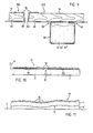
- FIG. 9 shows a detail of how the elastic longitudinal spars (spring bodies) 12, 12 ', 12 "can be inserted into tunnel tracks 32 in an easily replaceable manner.
- Tunnel track 32 is sewn onto fabric 21/25 by means of sewing points 31, 43, for example, either 8, or as shown in Figures 6 and 6A, the tunnel run 32 has a fastener 30 on the long side, which can be a zipper, Velcro fastener etc.
- the tunnel run is then to be opened in such a way that the elastic support elements are simple 12 can be removed from the tunnel train and reinserted, which is very useful, for example, if these elements have to be replaced or replaced due to wear or due to adaptation to a different user weight, for cleaning, etc.
- FIG. 10 shows another embodiment with a divided, that is to say partitioned, longitudinal spar 10.
- the cut P is made in the center of the longitudinal spar and allows the lying surface to be folded or folded.
- the couch can be folded up in a small space with two cuts P arranged in three.
- the folded couches can usually be stacked in a small space and thus take up little space.
- FIG. 11 finally shows the unloaded lying pad 10 on a rigid intermediate layer 4 'with an orthopedic profile S, for example, which intermediate layer 4' in turn rests on the (usual) base 4, 11, 11 '.
- Such intermediate layers can also only extend over part of the total length of the bed base. Further properties in connection with FIG. 11 have already been mentioned in the discussion of FIG. 4 (page 14 ff.).
Landscapes
- Mattresses And Other Support Structures For Chairs And Beds (AREA)
- Holders For Apparel And Elements Relating To Apparel (AREA)
- Thermotherapy And Cooling Therapy Devices (AREA)
- Bedding Items (AREA)
- Invalid Beds And Related Equipment (AREA)
- Special Chairs (AREA)
- Chairs For Special Purposes, Such As Reclining Chairs (AREA)
- Accommodation For Nursing Or Treatment Tables (AREA)
Claims (9)
Priority Applications (1)
| Application Number | Priority Date | Filing Date | Title |
|---|---|---|---|
| AT86905711T ATE59272T1 (de) | 1985-10-22 | 1986-10-16 | Ruhe- und liegeeinrichtung, vorzugsweise fuer ein bett. |
Applications Claiming Priority (4)
| Application Number | Priority Date | Filing Date | Title |
|---|---|---|---|
| CH453285 | 1985-10-22 | ||
| CH4532/85 | 1985-10-22 | ||
| CH3929/86 | 1986-10-01 | ||
| CH3929/86A CH670945A5 (en) | 1985-10-22 | 1986-10-01 | Under-frame for bed or couch |
Publications (2)
| Publication Number | Publication Date |
|---|---|
| EP0243383A1 EP0243383A1 (fr) | 1987-11-04 |
| EP0243383B1 true EP0243383B1 (fr) | 1990-12-27 |
Family
ID=25694203
Family Applications (1)
| Application Number | Title | Priority Date | Filing Date |
|---|---|---|---|
| EP86905711A Expired - Lifetime EP0243383B1 (fr) | 1985-10-22 | 1986-10-16 | Installation de repos, notamment pour lit |
Country Status (8)
| Country | Link |
|---|---|
| US (1) | US4827544A (fr) |
| EP (1) | EP0243383B1 (fr) |
| JP (1) | JPS63501132A (fr) |
| AT (1) | ATE59272T1 (fr) |
| CH (1) | CH670945A5 (fr) |
| DE (1) | DE3676690D1 (fr) |
| DK (1) | DK286687A (fr) |
| WO (1) | WO1987002559A1 (fr) |
Cited By (7)
| Publication number | Priority date | Publication date | Assignee | Title |
|---|---|---|---|---|
| DE4137677C1 (en) * | 1991-11-05 | 1992-11-19 | Futon-Affair Gmbh Japanische Betten, 6000 Frankfurt, De | Bottom frame for bed - has longitudinal stringers covered by flexible cross-slats |
| WO1999047027A1 (fr) | 1998-03-16 | 1999-09-23 | Das Bett Möbelhandels Gmbh | Sommier a lattes multicouches, destine notamment a du mobilier pour s'asseoir et s'allonger |
| US6122779A (en) * | 1997-05-20 | 2000-09-26 | Peter Meili | Bed base |
| EP1084664A1 (fr) | 1999-09-17 | 2001-03-21 | Meili & Co. AG | Support de couchage mobile |
| US6263528B1 (en) | 1998-01-16 | 2001-07-24 | HüSLER BALTHASAR | Leaning or sitting device |
| DE19930032C1 (de) * | 1999-06-30 | 2001-10-25 | Siegfried Heerklotz | Ruhe- und Liegeeinrichtung zum Einbau in ein Bettgestell |
| EP1169949A2 (fr) | 2000-06-28 | 2002-01-09 | Siegfried Dipl.-Ing. Heerklotz | Support pour des rembourrages, comme des matelas |
Families Citing this family (22)
| Publication number | Priority date | Publication date | Assignee | Title |
|---|---|---|---|---|
| US4903308A (en) * | 1988-02-10 | 1990-02-20 | Linaeum Corporation | Audio transducer with controlled flexibility diaphragm |
| DE8900377U1 (de) * | 1989-01-14 | 1989-03-30 | Backfisch, Kurt, 3501 Fuldabrueck | Bettgestell, bestehend aus einem viereckigen Rahmen |
| DE3933816A1 (de) * | 1989-10-10 | 1991-04-18 | Alpha Patentverwertungs Ges M | Bettunterbau |
| AU637628B2 (en) * | 1990-06-08 | 1993-06-03 | Silent Night Pty. Ltd. | Mattress inner assembly and mattress |
| US5070560A (en) * | 1990-10-22 | 1991-12-10 | Healthflex, Inc. | Pressure relief support system for a mattress |
| DE9100122U1 (de) * | 1991-01-08 | 1991-03-28 | Heerklotz, Siegfried, Dipl.-Ing., 4516 Bissendorf | Lattenrost für Polsterauflagen |
| DE9213403U1 (de) * | 1992-10-06 | 1993-05-06 | Neumann, Hans-Joachim, 8949 Stetten | Liegefläche eines Schlafsystems |
| AT400919B (de) * | 1992-12-22 | 1996-04-25 | Schneider Rudolf | Betteinsatz |
| JPH0737615Y2 (ja) * | 1992-12-25 | 1995-08-30 | パラマウントベッド株式会社 | ベッドにおけるボトム構造 |
| US5369826A (en) * | 1993-05-14 | 1994-12-06 | Paramount Bed Company Limited | Bottom structure of a bed |
| ATE174483T1 (de) * | 1993-09-08 | 1999-01-15 | Paramount Bed Kk | Untermatratze |
| EP0646341A1 (fr) * | 1993-09-30 | 1995-04-05 | Studio Hüsler Ag | Grille de support pour meuble d'assise ou de couchage, et éléments de support |
| AT511U1 (de) * | 1995-02-14 | 1995-12-27 | Pro Natura Naturprodukte Gmbh | Lattenrost |
| CA2146706C (fr) * | 1995-04-10 | 2000-08-01 | Ralph Harry Rossdeutscher | Lit |
| ATE341255T1 (de) | 2001-03-19 | 2006-10-15 | Huesler Studio Ag | Bandkombination zur positionierung von latten in einem lattenrost |
| US6637053B1 (en) * | 2002-06-07 | 2003-10-28 | Dinapoli Saverio | Mattress |
| CH696019A5 (de) * | 2002-09-03 | 2006-11-30 | Huesler Studio Ag | Vorrichtung zur Fixierung von Latten in einem flexiblen Lattenrost. |
| TWI266528B (en) * | 2004-04-20 | 2006-11-11 | Innolux Display Corp | LCD substrate support apparatus |
| US9504336B2 (en) * | 2013-02-13 | 2016-11-29 | Jon Dodd | Configurable bed |
| CA2946579C (fr) | 2014-04-24 | 2017-09-12 | Ashley Furniture Industries, Inc. | Plateau de siege rabattable pour ensembles meubles |
| JP2020005888A (ja) * | 2018-07-09 | 2020-01-16 | 貞信 松山 | 寝具用スプリング |
| CH719983B1 (de) | 2022-08-24 | 2024-04-15 | Buchmann Erwin | Vorrichtung zur Einstellung einer Neigung einer Liegefläche eines Betts. |
Family Cites Families (13)
| Publication number | Priority date | Publication date | Assignee | Title |
|---|---|---|---|---|
| US2225858A (en) * | 1939-11-09 | 1940-12-24 | Dunlop Tire & Rubber Corp | Mattress supporting structure |
| US2638606A (en) * | 1948-07-13 | 1953-05-19 | Dwight E Austin | Bed bottom |
| CH353860A (de) * | 1957-11-13 | 1961-04-30 | Degen Hugo | Liegemöbel-Gestell |
| CH382932A (de) * | 1957-11-13 | 1964-10-15 | Degen Hugo | Liegemöbel-Gestell |
| CH620581A5 (en) * | 1977-11-18 | 1980-12-15 | Superba Sa | Slatted mattress base |
| DE2832584C2 (de) * | 1978-07-25 | 1983-09-29 | Ludwig Dr.med. 3000 Hannover Zwehl | Liegemöbel, insbesondere Krankenbett |
| IT7953665V0 (it) * | 1978-11-21 | 1979-10-15 | Antonio Ferrer Martinez | Procedimento di montaggio applicabile alle reti a lame per letti |
| US4477935A (en) * | 1982-01-08 | 1984-10-23 | Griffin Gordon D | Mattress support system |
| DE3230494A1 (de) * | 1982-08-17 | 1984-02-23 | Günter 7981 Schlier Kreisner | Federleistenrost fuer liegemoebel mit schwimmend, verschiebbar im rahmen gelagerten querleisten |
| DE3232123A1 (de) * | 1982-08-28 | 1984-03-01 | Rummel & Co KG, 8530 Neustadt | Lattenrost als unterlage fuer eine matratze |
| US4559656A (en) * | 1982-12-28 | 1985-12-24 | Hill-Rom Company, Inc. | Hospital bed with a weight-distributing lever system |
| NZ202931A (en) * | 1983-01-06 | 1986-03-14 | G D Griffin | Air spring:support system for mattresses or chairs etc. |
| WO1985001425A1 (fr) * | 1983-09-30 | 1985-04-11 | Liform Ag | Surface de repos pour meuble, notamment pour lit |
-
1986
- 1986-10-01 CH CH3929/86A patent/CH670945A5/de not_active IP Right Cessation
- 1986-10-16 EP EP86905711A patent/EP0243383B1/fr not_active Expired - Lifetime
- 1986-10-16 JP JP61505271A patent/JPS63501132A/ja active Pending
- 1986-10-16 WO PCT/CH1986/000145 patent/WO1987002559A1/fr active IP Right Grant
- 1986-10-16 US US07/072,058 patent/US4827544A/en not_active Expired - Lifetime
- 1986-10-16 DE DE8686905711T patent/DE3676690D1/de not_active Expired - Lifetime
- 1986-10-16 AT AT86905711T patent/ATE59272T1/de not_active IP Right Cessation
-
1987
- 1987-06-03 DK DK286687A patent/DK286687A/da not_active Application Discontinuation
Cited By (8)
| Publication number | Priority date | Publication date | Assignee | Title |
|---|---|---|---|---|
| DE4137677C1 (en) * | 1991-11-05 | 1992-11-19 | Futon-Affair Gmbh Japanische Betten, 6000 Frankfurt, De | Bottom frame for bed - has longitudinal stringers covered by flexible cross-slats |
| US6122779A (en) * | 1997-05-20 | 2000-09-26 | Peter Meili | Bed base |
| US6263528B1 (en) | 1998-01-16 | 2001-07-24 | HüSLER BALTHASAR | Leaning or sitting device |
| WO1999047027A1 (fr) | 1998-03-16 | 1999-09-23 | Das Bett Möbelhandels Gmbh | Sommier a lattes multicouches, destine notamment a du mobilier pour s'asseoir et s'allonger |
| DE19930032C1 (de) * | 1999-06-30 | 2001-10-25 | Siegfried Heerklotz | Ruhe- und Liegeeinrichtung zum Einbau in ein Bettgestell |
| EP1084664A1 (fr) | 1999-09-17 | 2001-03-21 | Meili & Co. AG | Support de couchage mobile |
| EP1169949A2 (fr) | 2000-06-28 | 2002-01-09 | Siegfried Dipl.-Ing. Heerklotz | Support pour des rembourrages, comme des matelas |
| DE10030623C1 (de) * | 2000-06-28 | 2002-04-18 | Siegfried Heerklotz | Unterfederung für Polsterauflagen, wie Matratzen |
Also Published As
| Publication number | Publication date |
|---|---|
| WO1987002559A1 (fr) | 1987-05-07 |
| DK286687D0 (da) | 1987-06-03 |
| EP0243383A1 (fr) | 1987-11-04 |
| ATE59272T1 (de) | 1991-01-15 |
| CH670945A5 (en) | 1989-07-31 |
| JPS63501132A (ja) | 1988-04-28 |
| DK286687A (da) | 1987-06-22 |
| DE3676690D1 (de) | 1991-02-07 |
| US4827544A (en) | 1989-05-09 |
Similar Documents
| Publication | Publication Date | Title |
|---|---|---|
| EP0243383B1 (fr) | Installation de repos, notamment pour lit | |
| DE3936788C2 (fr) | ||
| EP0151218B1 (fr) | Matelas utilisés pour tout meuble, où l'on peut s'allonger, de préférence pour lits | |
| EP1056371B1 (fr) | Chassis de lit | |
| DE4320168C2 (de) | Liegefläche mit mindestens 3-facher Lattenebene | |
| AT390722B (de) | Einsatz fuer ein liegemoebel | |
| EP2904945B1 (fr) | Sommier à lattes doté d'une zone de support d'épaule pouvant être intégrée | |
| CH639546A5 (en) | Mattress | |
| DE1729961B1 (de) | Matratze oder Polsterung | |
| DE4205179A1 (de) | Liegeflaeche fuer betten, sofas und dergleichen | |
| EP2298135B1 (fr) | Meubles d'assise ou de couchage | |
| EP3069634B1 (fr) | Latte pour suspension a ressort equipant un siege ou un lit | |
| EP1063909B1 (fr) | Sommier a lattes multicouches, destine notamment a du mobilier pour s'asseoir et s'allonger | |
| EP0646341A1 (fr) | Grille de support pour meuble d'assise ou de couchage, et éléments de support | |
| DE9211519U1 (de) | Auflage für Liegeflächen | |
| EP0378746B1 (fr) | Lit, en particulier sommier à ressort avec cadre rectangulaire | |
| DE9004207U1 (de) | Liegefläche für Betten, Polstermöbel u.dgl. | |
| WO1994014359A1 (fr) | Element se plaçant sur ou dans un matelas | |
| DE202007008867U1 (de) | Anordnung mit einem Bettgestell und einer Kombinationsmatratze | |
| DE202007004007U1 (de) | Verstellbares Einzelfederelement eines Sitz- oder Liegemöbels | |
| DE2112506A1 (de) | Untermatratze | |
| DE4409093C2 (de) | Auflagefläche, insbesondere für ein Liegemöbel | |
| CH481613A (de) | Lattenrost für Matratzen und dergleichen | |
| DE4341349A1 (de) | Unterbau für Polsterelemente mit einer Vielzahl von zwischen zwei Seitenholmen parallel zueinander verlaufenden Latten | |
| EP0670128A1 (fr) | Sommier |
Legal Events
| Date | Code | Title | Description |
|---|---|---|---|
| PUAI | Public reference made under article 153(3) epc to a published international application that has entered the european phase |
Free format text: ORIGINAL CODE: 0009012 |
|
| 17P | Request for examination filed |
Effective date: 19870611 |
|
| AK | Designated contracting states |
Kind code of ref document: A1 Designated state(s): AT BE CH DE FR GB IT LI LU NL SE |
|
| RAP1 | Party data changed (applicant data changed or rights of an application transferred) |
Owner name: HUESLER-LIFORMA ENTWICKLUNGS AG |
|
| 17Q | First examination report despatched |
Effective date: 19890104 |
|
| GRAA | (expected) grant |
Free format text: ORIGINAL CODE: 0009210 |
|
| AK | Designated contracting states |
Kind code of ref document: B1 Designated state(s): AT BE CH DE FR GB IT LI LU NL SE |
|
| PG25 | Lapsed in a contracting state [announced via postgrant information from national office to epo] |
Ref country code: IT Free format text: LAPSE BECAUSE OF FAILURE TO SUBMIT A TRANSLATION OF THE DESCRIPTION OR TO PAY THE FEE WITHIN THE PRE;WARNING: LAPSES OF ITALIAN PATENTS WITH EFFECTIVE DATE BEFORE 2007 MAY HAVE OCCURRED AT ANY TIME BEFORE 2007. THE CORRECT EFFECTIVE DATE MAY BE DIFFERENT FROM THE ONE RECORDED.SCRIBED TIME-LIMIT Effective date: 19901227 Ref country code: SE Free format text: THE PATENT HAS BEEN ANNULLED BY A DECISION OF A NATIONAL AUTHORITY Effective date: 19901227 Ref country code: NL Effective date: 19901227 Ref country code: GB Effective date: 19901227 Ref country code: FR Effective date: 19901227 Ref country code: BE Effective date: 19901227 |
|
| REF | Corresponds to: |
Ref document number: 59272 Country of ref document: AT Date of ref document: 19910115 Kind code of ref document: T |
|
| REF | Corresponds to: |
Ref document number: 3676690 Country of ref document: DE Date of ref document: 19910207 |
|
| NLV1 | Nl: lapsed or annulled due to failure to fulfill the requirements of art. 29p and 29m of the patents act | ||
| EN | Fr: translation not filed | ||
| GBV | Gb: ep patent (uk) treated as always having been void in accordance with gb section 77(7)/1977 [no translation filed] | ||
| PLBE | No opposition filed within time limit |
Free format text: ORIGINAL CODE: 0009261 |
|
| STAA | Information on the status of an ep patent application or granted ep patent |
Free format text: STATUS: NO OPPOSITION FILED WITHIN TIME LIMIT |
|
| 26N | No opposition filed | ||
| EPTA | Lu: last paid annual fee | ||
| PGFP | Annual fee paid to national office [announced via postgrant information from national office to epo] |
Ref country code: CH Payment date: 20051020 Year of fee payment: 20 |
|
| PGFP | Annual fee paid to national office [announced via postgrant information from national office to epo] |
Ref country code: AT Payment date: 20051024 Year of fee payment: 20 |
|
| PGFP | Annual fee paid to national office [announced via postgrant information from national office to epo] |
Ref country code: LU Payment date: 20051028 Year of fee payment: 20 |
|
| PGFP | Annual fee paid to national office [announced via postgrant information from national office to epo] |
Ref country code: DE Payment date: 20051221 Year of fee payment: 20 |
|
| REG | Reference to a national code |
Ref country code: CH Ref legal event code: PL |