EP0243383B1 - Installation for resting and lying down, preferably for a bed - Google Patents
Installation for resting and lying down, preferably for a bed Download PDFInfo
- Publication number
- EP0243383B1 EP0243383B1 EP86905711A EP86905711A EP0243383B1 EP 0243383 B1 EP0243383 B1 EP 0243383B1 EP 86905711 A EP86905711 A EP 86905711A EP 86905711 A EP86905711 A EP 86905711A EP 0243383 B1 EP0243383 B1 EP 0243383B1
- Authority
- EP
- European Patent Office
- Prior art keywords
- reclining
- longitudinal members
- lying
- means according
- covering
- Prior art date
- Legal status (The legal status is an assumption and is not a legal conclusion. Google has not performed a legal analysis and makes no representation as to the accuracy of the status listed.)
- Expired - Lifetime
Links
Images

Classifications
-
- A—HUMAN NECESSITIES
- A47—FURNITURE; DOMESTIC ARTICLES OR APPLIANCES; COFFEE MILLS; SPICE MILLS; SUCTION CLEANERS IN GENERAL
- A47C—CHAIRS; SOFAS; BEDS
- A47C23/00—Spring mattresses with rigid frame or forming part of the bedstead, e.g. box springs; Divan bases; Slatted bed bases
- A47C23/06—Spring mattresses with rigid frame or forming part of the bedstead, e.g. box springs; Divan bases; Slatted bed bases using wooden springs, e.g. of slat type ; Slatted bed bases
- A47C23/062—Slat supports
- A47C23/063—Slat supports by elastic means, e.g. coil springs
-
- A—HUMAN NECESSITIES
- A47—FURNITURE; DOMESTIC ARTICLES OR APPLIANCES; COFFEE MILLS; SPICE MILLS; SUCTION CLEANERS IN GENERAL
- A47C—CHAIRS; SOFAS; BEDS
- A47C23/00—Spring mattresses with rigid frame or forming part of the bedstead, e.g. box springs; Divan bases; Slatted bed bases
- A47C23/06—Spring mattresses with rigid frame or forming part of the bedstead, e.g. box springs; Divan bases; Slatted bed bases using wooden springs, e.g. of slat type ; Slatted bed bases
-
- A—HUMAN NECESSITIES
- A47—FURNITURE; DOMESTIC ARTICLES OR APPLIANCES; COFFEE MILLS; SPICE MILLS; SUCTION CLEANERS IN GENERAL
- A47C—CHAIRS; SOFAS; BEDS
- A47C23/00—Spring mattresses with rigid frame or forming part of the bedstead, e.g. box springs; Divan bases; Slatted bed bases
- A47C23/30—Spring mattresses with rigid frame or forming part of the bedstead, e.g. box springs; Divan bases; Slatted bed bases using combinations of springs covered by more than one of the groups A47C23/04, A47C23/06 and A47C23/12; Frames therefor
Definitions
- the invention relates to a resting and lying device according to the preamble of the independent claim.
- the current state of the art in slatted frame battens is designed to flexibly support resilient cross slats, the individual slat forming the main spring element.
- the crossbar claimed as the main spring element usually has a complicated multilayer gluing in order to realize the so-called cant (arch).
- the elevation serves to ensure that the individual spring slats are bent straight in the event of a load and thus the lying surface becomes "flat”.
- This load-dependent Leige "level” is matched to the load of an average (usually 170 cm tall and 70 kg heavy) people.
- the known slatted frame beds are still relatively solid and heavy constructions with a large number of individual elements such as position stabilizers of the slats, usually arranged in the center, terminal flex elements and their attachment to the slat and frame (these constructions require a frame) and in a kind of refinement with additional battens and special battens, all mostly in distinctive colors and more.
- DE-A-2 949 348 takes a somewhat different approach, in which a mattress base is designed in such a way that an upper frame with a slatted frame rests on elastic elements, which in turn are carried by a lower frame. Thanks to the elastic elements, a more or less flexible support of the upper frame is achieved, but the entire construction is - due to the two fixed connections and consequently rigid frame - relatively cumbersome (e.g. during transport, moving). In addition, there is a spring effect only with respect to the entire upper frame, but not with respect to the individual crossbars of the upper frame that support the mattress.
- EP-A-0 116 237 which consists only of two inflatable longitudinal spars, each of which has a row of pockets oriented transversely to the longitudinal direction on its upper side, so that a number of transverse battens, the ends of each in a pocket of the parallel longitudinal spars are inserted, a rust-like structure is created.
- it is a construction that is more suitable for temporary use, since stability is hardly guaranteed over a long period of use. Since the cot is only held together by the crossbars in the pockets, there is a risk that the crossbars will exist even with low horizontal forces between the two longitudinal spars (e.g. when moving, carrying around, or even if they are only exposed to the intended use) slide out of your pockets and the reclining device breaks down into its individual components. Since the pockets tend to expand when used, the stability of this device decreases with age.
- the invention is therefore based on the object of creating a resting and lying device of the type mentioned at the outset and developing it in such a way that the various requirements mentioned above (criteria a, b, c) are ensured in a simple and economical manner together with a controllable spring action.
- the lying plane With the lying plane according to the invention, a uniform suspension which can be adapted to the different human bodies is ensured over the entire surface, ie the lying plane functions together with the human body independently of the mattress.
- the suspension is essentially due to the elasticity of the longitudinally extending support elements (Lähgspolme, spring body) and not defined by the slatted elements lying in a rust-like arrangement and is preferably adapted to the weight of the respective user by the spring body.
- the lying surface remains flat and is only perceived as too hard or too soft.
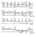
- Figures 1 and 2 branch in a stylized representation of a functional example of a slatted bed surface according to the prior art, compared to one according to the invention. They show the fundamental difference in spring dynamics, how it can come about through the invention on the one hand and how it is common today on the other hand.
- Both stylized slatted bed surfaces of Figures 1 and 2 have as primary elements a longitudinal spar 1, which in the prior art can also be a rigid bed frame between which the slats are attached, and crossbars connected to the longitudinal spar. Both structures have a stress curve B superimposed on them, drawn in and both structures react in their characteristic way with a stress profile or a lying curve L.
- Figure 1 shows the lying surface with a rigid longitudinal beam 1, a slat suspension with crossbars 2 in a list 20 to 27 and with slats 3 in the list 30 to 37, which perform their usual spring task in the longitudinal direction.
- the dashed stress curve B is chosen so that the elastic adaptation of the structure is heavily stressed.
- Figure 1A shows the reaction to this load case.
- the slats 30, 31, 32 are evenly lightly loaded and the spring elements 20, 21, 22 hardly show any deformation.
- the slat 33 is loaded obliquely and the spring element 23 is deformed on one side.
- the spring elements are pushed all the way through, the resulting lying curve being distorted in the area of the spring elements in relation to the load curve.
- FIG. 2A It is quite different with the bed according to the invention in FIG. 2.
- the primary elements are supported on a solid (non-resilient) base 4, for example on the floor.
- These are elastic longitudinal spars 1 (spring body) with resting slats 3 supported thereon, which are generally straight, that is to say they have no functional bend and do not have to perform any special spring function in their longitudinal direction when loaded.
- the entire suspension task is thus transferred to the elastic longitudinal bars (spring body).
- the same load curve B as already shown in FIG. 1A, is also shown superimposed here. The effect of this load case is shown in Figure 2A.
- the lying curve L coincides with the load curve B over the entire width of the bed, which means that there is no distortion in the outer or edge area and there is therefore no significant suspension deficit D.
- the construction according to the invention is therefore able to adapt better to an anatomical load profile .
- the above-mentioned orthopedic teaching is fulfilled in that the elasticity of the longitudinal spars (spring body) corresponds to the weight of the user is chosen speaking. If a material that is too soft is used, there is still no sagging in the longitudinal direction, since the spring stroke is limited by the fixed base 4, which itself does not spring. If a material that is too hard is used, the user is still not too high because no pre-stressed crossbars are used.
- the lying surface is only perceived as somewhat hard. In embodiments described later, these can be easily adapted.
- the anatomical load profile is significantly more important in the longitudinal direction than in the transverse direction. So far, if greater efforts have been made to construct slatted bed frames mainly in the transverse direction than in the longitudinal direction, this was due to the general development of this type of bed. The first efforts were aimed only at the springy effect of the then rigid slats, which were only later flexibly attached. Since then, there has been no fundamental change, despite the constant effort to achieve as much spring comfort as possible in the longitudinal direction.
- the lead surface construction according to the inventive idea allows unusually light and, in addition, simple embodiments.
- such beds can be placed directly on the floor or in a conventional manner in a bed frame.
- This allows a variety of uses, for example, as a camping bed, as an emergency bed, as a normal bed, as a wall bed, etc., without sacrificing quality of lying comfort, which is quite remarkable in the price range of a camping bed. If you consider that all of the above-mentioned applications each have their own design and there are enormous differences in quality, the bedding, which brings all this down to a common denominator, is a very advanced concept.
- FIG. 3 shows the essential parts of a document structure, designated in its entirety by 10, in a sectional view and in FIG. 4 in a side view.
- the underlay structure 10 comprises at least two longitudinal spars (spring bodies) 12, 12 ', or 1 according to FIGS. 2, 2A, which are arranged at a parallel spacing from one another and run in the longitudinal direction of the underlay structure, on which a plurality of transverse battens 13 which are essentially oriented transversely thereto are arranged.
- the individual transverse slats 13 arranged at a distance from one another form a slatted frame designated as a whole by 14.
- the fixed, non-resilient base 4 designated according to FIGS. 2, 2A is referred to as support spars.
- the document structure 10 'shown in FIG. 5 largely corresponds to the document structure 10 described above with reference to FIGS. 3, 4.
- three longitudinal spars (spring bodies) 12, 12', 12 "arranged at a distance from one another are provided, for example. for a double bed or when using softer material for the longitudinal spars 12 (spring body).
- the approximately regularly spaced transverse slats 13 are operatively connected to the longitudinal spars (spring bodies) 12, 12 ', 12 "in a manner not shown in detail and together form essentially a structural unit which, in accordance with the longitudinal spars (spring bodies) 12, 12', 12 "assigned carriers 11, 11 ', 11" of a bed box or bed frame, not shown, or lie on the floor.
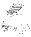
- FIG. 6 shows a base structure 20 which comprises two or more integrated longitudinal spars (spring bodies) 22, 22 ', 22 "which are arranged at a distance from one another, a large number of transverse slats 23 and a film-like beam 25.
- the beam 25 essentially consists of a central part 25 'connecting the support elements 22, 22' and two side parts 21, 21 '.
- the side parts 21, 21' are provided with pockets 24, 24 'arranged at a distance from one another in the longitudinal direction of the underlay structure 20, which are designed to receive the crossbars 23.
- a film-like cover 28 (dashed line) covering the crossbars 23 can be provided, which in the area of the pockets 24, 24 'has a total length of the underlay structure 20 running zipper (not shown) is connected to the beam 25.
- a light top mattress preferably a futon (Japanese bed), not shown here, can be placed loosely on the slatted frame 14.
- a futon Japanese bed
- such a mattress is much cheaper than a mattress in the traditional sense.
- FIG. 6A shows a modified embodiment based on FIG. 5, in which the cover 28 is stretched only over a medium-length, spring-acting longitudinal bar (spring body) 12 ", while the two outer, laterally running, spring-acting longitudinal bars (spring body) 12
- outer longitudinal spars spring bodies
- FIG. 7 shows a part of a document structure 10 "in a perspective top view.
- This document structure 10" essentially corresponds with the parts 11 ', 12', 13 of the document structure 10 and 10 'according to FIGS. 3, 4 and 5.
- This in this exemplary embodiment has a share spaced pockets.
- the Darge in Fig. 7 The partial section shows one side of the underlay structure 10 "and the side part 31 'with the pockets 34' can be seen, in which the crossbars 13 are inserted and held in a form-fitting manner trained (not shown).
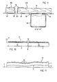
- FIG. 8 shows, as a further embodiment, a type of clothing that differs from that shown in FIGS. 6 and 7 and that goes beyond that of FIG. 6A.
- the underlay structure is formed by a plurality, preferably two or three, of integrated longitudinal bars (spring bodies) 12, 12 ', 12 ", a plurality of transverse slats 13 and a covering 40.
- the covering with the aforementioned pockets 24, 34 now runs completely along the crossbars 13; the longitudinal support elements 12, 12 ', 12 "are inserted into tunnel strips 32 sewn onto the covering, details of which will be discussed in connection with FIG. 9.
- the covering 40 runs relatively well in the crossbar direction so that the battens remain in their assigned pockets (FIGS. 6, 7, 8) in every load case.
- the crossbars 13 normally do not bend.
- the slats are preferably made of non-glued solid wood, are 8-12 mm thick, have no cant and are therefore easy to manufacture. These slats are deflected at most under extreme point loads, for example when standing or jumping on such a structure. In this case, it may happen that a crossbar slips out of its pocket holder, but it is very easy to put it back into its holder, for example with the help of a shoehorn.
- the longitudinal spars (spring bodies) 1, 12, 12 ', 12 "and 22, 22' shown in the figures are basically designed as resilient molded parts.
- longitudinal spars (spring body) 12, 12 ', 12 "have full profile cross-section and are made of elastic material, for example latex foam, cellular rubber, foams or the like with polygonal, cuboid, circular or elliptical A square cross-section of 50-70 mm is recommended for children's beds, and 70-100 mm for adult beds, in order to ensure the full spring stroke required.
- Preferred materials are soft materials, especially soft-foamed latex, so that the longitudinal spars can be pulled through adjust the dead weight of the lying surface to a predetermined contour of the rigid surface 4, 11.
- the longitudinal spars (spring bodies) 22, 22 'shown in FIG. 6 are designed as a tubular hollow body and can have a cuboid, circular or elliptical profile cross section. These longitudinal spars (spring bodies) are designed as inflatable hollow bodies, on which the side parts 21, 21 'and the central part 25' of the beam 25 are molded or welded.
- the individual, slat-like transverse slats 13 in their entirety form the slatted frame designated by 14.
- the single crossbar 13 is preferably made of non-glued solid wood. Layer-glued Fournier wood, plastic with a suitable shape, extrudal profiles or relatively thin steel sheet or the like can be used as the further material for the production of the crossbars 13.
- the distance between the individual crossbars 13 is preferably in the order of magnitude of 10-20 mm for all embodiments, so that there is sufficient support and suspension of the body resting on the base structure and an optimal one. Moisture exchange (ventilation) is guaranteed.
- the crossbars 13 preferably have the following dimensions: thickness 8-12 mm, width 20-45 mm, length 70-120 mm.
- the cantilever length, the protrusion over the longitudinal spars (central axis) is preferably 10-15%.
- the individual crossbars 13 are inserted into the spaced apart pockets 34 and thus fixed in their position (see Fig. 4).
- the crossbars 13 inserted into the pockets 24, 24 ', 34' can be removed from the pockets, turned or replaced without special aids.
- the individual crossbars 13 can be placed on the longitudinal spars (spring bodies) 12, 12 ', 12 "and held together by means not shown, for example by a band (loops) or the like not shown be or be operatively connected by gluing to the longitudinal spars (spring body) 12, 12 ', 12 ".
- corresponding recesses arranged at a distance from one another can be provided in the longitudinal spars (spring bodies) 12, 12 ', 12 "for fixing the position of the transverse slats 13.
- the embodiment according to FIG. The like. and is placed directly on the floor.
- the underlay structure 20 has inflatable longitudinal spars (spring bodies) 22, 22 'which form with the beam 25 or flexible longitudinal spars (spring bodies) 12 which form a unit with the covering 40.
- the required prestressing of the beam 25 is generated here by the crossbars 13 inserted into the pockets 24, 24 '.
- a cloth covering, which is preferably provided with a decorative pattern (not shown) on the support surface 26, can be provided as the underframe 25 or covering 40, so that these light lying underlays, for example, can be set up and used as a decorative wall Eyelets 29 can be detachably attached. On these eyelets, the light bed structure can also be hung on a wardrobe-like frame, together with the light, thin, mattress-like overlay (futon).
- the underlay structures 10, 10 'and 20 can be used both as a single resting bed or as a mass storage facility and can be held together by means of the eyelets 29 or cross closures R1 / R2.
- a further advantage is that the underlay structure 20 with the inflatable longitudinal spars (spring body) 22, 22 'according to FIG. 6 can be rolled up in the longitudinal direction in the non-inflated state or, in the embodiment according to FIG. 10, can be folded up and by means of zippers R1 / R2 are held together and thus form an easily transportable, compact unit. The latter can conveniently be used as a bag at the same time.
- the underlay structure 10, 10 ', 10 "and 20 can be divided into individual zones K, R and B of different hardness, which extend over the entire length, with K the head part, R the trunk part and the leg section is designated B.
- K the head part
- R the trunk part
- the leg section is designated B.
- the firm, non-resilient support 4, 11 is separated by profiled but rigid intermediate bodies 4 ' Longitudinal spars 1, 12 and base 4, 11 arranged, brought into the desired anatomically required shape (lying profile). Due to the "softness" of the longitudinal spars (spring body), the lying base follows the desired shape (lying profile) given by the intermediate body 4 '.
- the couch pad is placed either on a rigid pad 4 or on rigid support bars 11, 11 ', for example in a bed frame.
- the invention thus essentially comprises a base structure 10 or 20 with at least two longitudinal spars (spring bodies) 12, 12 'or 22, 22' oriented in the longitudinal direction and spaced from one another, which act resiliently perpendicular to their load and with the approximately regularly arranged and crossbars 13 of the slatted frame 14 which are operatively connected therewith are designed as a structural unit.
- a cloth construction is preferably used to form the structural unit.
- FIG. 9 shows a detail of how the elastic longitudinal spars (spring bodies) 12, 12 ', 12 "can be inserted into tunnel tracks 32 in an easily replaceable manner.
- Tunnel track 32 is sewn onto fabric 21/25 by means of sewing points 31, 43, for example, either 8, or as shown in Figures 6 and 6A, the tunnel run 32 has a fastener 30 on the long side, which can be a zipper, Velcro fastener etc.
- the tunnel run is then to be opened in such a way that the elastic support elements are simple 12 can be removed from the tunnel train and reinserted, which is very useful, for example, if these elements have to be replaced or replaced due to wear or due to adaptation to a different user weight, for cleaning, etc.
- FIG. 10 shows another embodiment with a divided, that is to say partitioned, longitudinal spar 10.
- the cut P is made in the center of the longitudinal spar and allows the lying surface to be folded or folded.
- the couch can be folded up in a small space with two cuts P arranged in three.
- the folded couches can usually be stacked in a small space and thus take up little space.
- FIG. 11 finally shows the unloaded lying pad 10 on a rigid intermediate layer 4 'with an orthopedic profile S, for example, which intermediate layer 4' in turn rests on the (usual) base 4, 11, 11 '.
- Such intermediate layers can also only extend over part of the total length of the bed base. Further properties in connection with FIG. 11 have already been mentioned in the discussion of FIG. 4 (page 14 ff.).
Landscapes
- Mattresses And Other Support Structures For Chairs And Beds (AREA)
- Bedding Items (AREA)
- Holders For Apparel And Elements Relating To Apparel (AREA)
- Thermotherapy And Cooling Therapy Devices (AREA)
- Invalid Beds And Related Equipment (AREA)
- Chairs For Special Purposes, Such As Reclining Chairs (AREA)
- Accommodation For Nursing Or Treatment Tables (AREA)
- Special Chairs (AREA)
Abstract
Description
Die Erfindung bezieht sich auf eine Ruhe- und Liegeeinrichtung gemäss dem Oberbegriff des unabhängigen Patentanspruchs.The invention relates to a resting and lying device according to the preamble of the independent claim.
Der fortschreitenden konstruktiven Entwicklung derartiger Ruhe- und Liegeeinrichtungen liegen im wesentlichen die nachstehend aufgeführten Kriterien zugrunde, und zwar:
- a. aus der Sicht der Orthopädie ist die gesamte Liegefläche so auszubilden, dass abhängig von Gewicht, Grösse und Liegeeigenschaft (Ruheposition) der Körper des Benutzers optimal abgestützt ist und in entspannter Lage ruhen kann;
- b. aus der Sicht der Hygiene ist die vom Benutzer abgegebene Feuchtigkeit ausreichend abzuleiten und die Atmungsfähigkeit (Belüftung) zu gewährleisten; und
- c. aus der Sicht der Handhabung wird unter Beibehaltung der Liege- und Ruhequalität eine möglichst leichte und einfache Ausgestaltung (Konstruktion) bei gleichzeitiger Wahrung der Stabilität angestrebt.
- a. From the orthopedic point of view, the entire lying surface should be designed in such a way that the user's body is optimally supported and can rest in a relaxed position, depending on weight, size and lying position (rest position);
- b. from the point of view of hygiene, the moisture released by the user must be adequately drained off and the breathability (ventilation) must be guaranteed; and
- c. From the point of view of handling, the aim is to keep the lying and resting quality as light and simple as possible (construction) while maintaining stability.
Der heutige Stand der Technik bei Lattenrost-Batten ist darauf ausgerichtet, federnde Querlatten flexibel abzustützen, wobei die einzelne Latte das Haupt-Federelement bildet. Die als Hauptsächliches Federelement beanspruchte Latte weist in der Regel eine komplizierte mehrschichtige Verleimung auf, um die sogenannte Überhöhung (Bogen) zu realisieren. Die Überhöhung dient dazu, dass im Belastungsfall die einzelnen Federlatten geradegebogen werden und damit die Liegefläche "eben" wird. diese belastungsabhängige Leige "ebene" ist auf die Belastung eines durchschnittlichen (in der Regel 170 cm grossen und 70 kg schweren) Menschen abgestimmt. Dies hat unter anderem den bekannten Nachteil, dass eine leichtere, beispielsweise bis 50 kg schwere, Person auf der Überhöhung liegend an Schlafkomfort einbüsst, gleich wie eine schwerere, beispielsweise 90 kg schwere, Person auf eingesunkenen Latten. Es liegt in diesen Fällen eine, von der Gesamtfederwirkung aus gesehen, unkontrollierbare Federung vor. Die Zusammenwirkung mit einer genügend dicken Matratze mildert diese Inkommodität, aber im Prinzip bleibt der grundlegende Mangel doch bestehen.The current state of the art in slatted frame battens is designed to flexibly support resilient cross slats, the individual slat forming the main spring element. The crossbar claimed as the main spring element usually has a complicated multilayer gluing in order to realize the so-called cant (arch). The elevation serves to ensure that the individual spring slats are bent straight in the event of a load and thus the lying surface becomes "flat". this load-dependent Leige "level" is matched to the load of an average (usually 170 cm tall and 70 kg heavy) people. Among other things, this has the known disadvantage that a lighter person, for example weighing up to 50 kg, lying on the curb, loses sleep comfort, just like a heavier person, for example weighing 90 kg, on sunken slats. In these cases, there is an uncontrollable suspension, seen from the overall spring effect. Interaction with a sufficiently thick mattress alleviates this incompatibility, but in principle the basic shortcoming remains.
Ferner sind die bekannten Lattenrost-Betten noch heute verhältnismässig massive und schwere Konstruktionen mit einer Vielzahl von Einzelelementen wie Lagestabilisatoren der Latten, meist mittig angeordnet, endständige Flexelemente und deren Befestigung an Latte und Rahmen (diese Konstruktionen setzen einen Rahmen voraus) sowie in einer Art Verfeinerung mit Zusatzlatten und Speziallatten, alle meist in kennzeichnenden Farben und anderes mehr. Das heisst, dass zur Erzeilung einer befriedigenden individuellen Federwirkung ein grosser Aufwand nötig ist, der trotzdem nicht immer zum Ziel führt.Furthermore, the known slatted frame beds are still relatively solid and heavy constructions with a large number of individual elements such as position stabilizers of the slats, usually arranged in the center, terminal flex elements and their attachment to the slat and frame (these constructions require a frame) and in a kind of refinement with additional battens and special battens, all mostly in distinctive colors and more. This means that a great deal of effort is required to achieve a satisfactory individual spring effect, which nevertheless does not always lead to the goal.
Einen etwas unterschiedlichen Weg geht die DE-A-2 949 348, bei welcher ein Matratzenboden so asugestaltet ist, dass ein oberer Rahmen mit einem Lattenrost auf elastischen Elementen ruht, welche ihrerseits von einem unteren Rahmen getragen werden. Dank der elastischen Elemente wird zwar eine mehr oder weniger flexible Abstützung des Oberrahmens erreict, die gesamte Konstruktion ist jedoch-bedingt durch die beiden aus festgefügten Verbindungen bestehenden und demzufolge starren Rahmen-relativ schwerfällig (z.B. beim Transport, Verschieben). Zudem besteht eine Federwirkung nur bezüglich des gesamten Oberrahmens, nicht aber bezüglich der einzelnen, die Matratze tragenden Querlatten des Oberrahmens.DE-A-2 949 348 takes a somewhat different approach, in which a mattress base is designed in such a way that an upper frame with a slatted frame rests on elastic elements, which in turn are carried by a lower frame. Thanks to the elastic elements, a more or less flexible support of the upper frame is achieved, but the entire construction is - due to the two fixed connections and consequently rigid frame - relatively cumbersome (e.g. during transport, moving). In addition, there is a spring effect only with respect to the entire upper frame, but not with respect to the individual crossbars of the upper frame that support the mattress.
Eine leichtere Konstruktion wird in der EP-A-0 116 237 vorgeschlagen, welche lediglich aus zwei aufblasbaren Längsholmen besteht, welche an ihrer Oberseite je eine Reihe quer zur Längsrichtung orientierter Taschen aufweisen, sodass durch eine Anzahl von Querlatten, deren Enden je in eine Tasche der parallel angeordneten Längsholmen eingeführt werden, eine rostartige Struktur entsteht. Es handelt sich dabei jedoch um eine eher für den vorübergehenden Gebrauch geeignete Konstruktion, da die Stabilität bei längerem Einsatz kaum gewährleistet ist. Da der Zusammenhalt der Liegeeinrichtung bloss durch den Sitz der Querlatten in den Taschen gewährleistet ist, besteht schon bei geringen Horizontalkräften zwischen den beiden Längsholmen (z.B. beim Verschieben, Herumtragen, u.U. sogar bei der blossen Belastung durch die bestimmungsgemässe Benutzung) die Gefahr, dass die Querlatten aus den Taschen gleiten und die Liegeeinrichtung in ihre Einzelbestandteile zerfällt. Da die Taschen durch den Gebrauch zudem eher ausgeweitet werden, reduziert sich die Stabilität dieser Vorrichtung mit zunehmendem Alter.A lighter construction is proposed in EP-A-0 116 237, which consists only of two inflatable longitudinal spars, each of which has a row of pockets oriented transversely to the longitudinal direction on its upper side, so that a number of transverse battens, the ends of each in a pocket of the parallel longitudinal spars are inserted, a rust-like structure is created. However, it is a construction that is more suitable for temporary use, since stability is hardly guaranteed over a long period of use. Since the cot is only held together by the crossbars in the pockets, there is a risk that the crossbars will exist even with low horizontal forces between the two longitudinal spars (e.g. when moving, carrying around, or even if they are only exposed to the intended use) slide out of your pockets and the reclining device breaks down into its individual components. Since the pockets tend to expand when used, the stability of this device decreases with age.
Der Erfindung liegt deshalb die Aufgabe zugrunde, eine Ruhe- und Liegeeinrichtung der eingangs genannten Art zu schaffen und so weiterzubilden, dass die verschiedenen vorangehend angesprochenen Anforderungen (Kriterien a, b, c) zusammen mit einer kontrollierbaren Federwirkung auf einfache und wirtschaftliche Weise gewährleistet werden.The invention is therefore based on the object of creating a resting and lying device of the type mentioned at the outset and developing it in such a way that the various requirements mentioned above (criteria a, b, c) are ensured in a simple and economical manner together with a controllable spring action.
Diese Aufgabe wird durch die im unabhängigen Anspruch gekennzeichnete Erfindung gelöst. Die federnd wirkenden Längsholme und die rostartig über diesen angeordneten. Querlatten werden durch eine Bespannung (Tuch, Folie etc.) miteinander verbunden und relativ zueinander fixiert. So entsteht eine leichte,-aus wenigen Einzelteilen bestehende und den Körper optimal abstützende Baueinheit. Diese kann auf einfache Weise zusammengebaut bzw. zerlegt werden und gewährleistet hinreichende Stabilität, selbst bei Dauereinsatz.This object is achieved by the invention characterized in the independent claim. The resilient longitudinal spars and the rust-like arranged above them. Crossbars are connected to each other by a covering (cloth, foil, etc.) and fixed relative to each other. The result is a lightweight unit consisting of a few individual parts and optimally supporting the body. This can be easily assembled or disassembled and ensures sufficient stability, even with continuous use.
Mit der erfindungsgemässen Liegeebene wird über die gesamte Fläche eine gleichmässige, den unterschiedlichen menschlichen Körpern anpassbare Federung gewährleistet, d.h. dass die Liegeebene unabhängig von der Matratze mit dem meschlichen Körper zusammenfunktioniert. Die Federung wird im wesentlichen durch die Elastizität der in Längsrichtung verlaufenden Trägerelemente (Lähngsholme, Federkörper) und nicht durch die in rostähnlicher Anordnung liegenden Lattenelemente definiert und ist vorzugsweise dem Gewicht des jeweiligen Benutzers durch die Federkörper entsprechend angepasst. Bei Fehlanpassung bleibt die Liegefläche trotzdem eben und wird lediglich als zu hart oder zu weich empfunden.With the lying plane according to the invention, a uniform suspension which can be adapted to the different human bodies is ensured over the entire surface, ie the lying plane functions together with the human body independently of the mattress. The suspension is essentially due to the elasticity of the longitudinally extending support elements (Lähgspolme, spring body) and not defined by the slatted elements lying in a rust-like arrangement and is preferably adapted to the weight of the respective user by the spring body. In the event of a mismatch, the lying surface remains flat and is only perceived as too hard or too soft.
Ausfuehrungsbeispiele der Erfindung sind in den Zeichnungen dargestellt und werden im folgenden naeher beschrieben. Die Einzelheiten der Figuren geben wesentliche Merkmale der Erfindung wieder. Es zeigt:
- Fig. 1A, B ein in Seitenansicht dargestelltes Funktionsbild einer unbelasteten und einer belasteten Liegefläche gemäss Stand der Technik,
- Fig. 2A, B ein in Seitenansicht dargestelltes Funktionsbild einer unbelasteten und einer belasteten Liegefläche gemäss Erfindung,
- Fig. 3 ein in Schnittansicht dargestelltes erstes Ausfuehrungsbeispiel einer Unterlagenstruktur fuer eine Ruhe- und Liegeeinrichtung;
- Fig. 4 die in Seitenansicht dargestellte Unterlagenstruktur gemaess Fig. 1;
- Fig. 5 ein zweites, in Schnittansicht dargestelltes Ausfuehrungsbeispiel der Unterlagenstruktur;
- Fig. 6 ein drittes Ausfuehrungsbeispiel einer Unterlagenstruktur;
- Fig. 6A ein viertes Ausfuehrungsbeispiel einer Unterlagenstruktur;
- Fig. 7 ein Teilstueck der in perspektivischer Draufsicht dargestellten Unterlagenstruktur gemaess Fig.3 und Fig. 3;
- Fig. 8 ein fünftes Ausführungsbeispiel einer Unterlagenstruktur gemäss den Figuren 3 und 5 in Abwandlung des Ausführungsbeispiels nach Figur 6;
- Fig. 9 ein Teilstück der Unterlagenstruktur gemäss
Figur 11; - Fig. 10 ein sechstes Ausführungsbeispiel einer Unterlagenstruktur mit partioniertem Federelement in Längsrichtung;
- Fig. 11 ein siebentes Ausführungsbeispiel einer Unterlagenstruktur mit profilierter Zwischenlage bspw. für orthopädische Zwecke.
- 1A, B is a side view of a functional image of an unloaded and a loaded lying surface according to the prior art,
- 2A, B is a side view of a functional image of an unloaded and a loaded lying surface according to the invention,
- 3 shows a first exemplary embodiment of a supporting structure for a resting and lying device, shown in a sectional view;
- 4 shows the document structure shown in side view according to FIG. 1;
- 5 shows a second exemplary embodiment of the underlay structure, shown in a sectional view;
- 6 shows a third exemplary embodiment of a document structure;
- 6A shows a fourth exemplary embodiment of a document structure;
- 7 shows a part of the document structure shown in a perspective top view according to FIGS. 3 and 3;
- 8 shows a fifth exemplary embodiment of a document structure according to FIGS. 3 and 5 in a modification of the exemplary embodiment according to FIG. 6;
- 9 shows a part of the document structure according to FIG. 11;
- 10 shows a sixth exemplary embodiment of a base structure with a partitioned spring element in the longitudinal direction;
- 11 shows a seventh exemplary embodiment of a base structure with a profiled intermediate layer, for example for orthopedic purposes.
Die Figuren 1 und 2 zweigen in stilisierter Darstellung ein Funktionsbeispiel einer Lattenrost-Liegefläche gemäss Stand der Technik, im Vergleich zu einer solchen gemäss Erfindung. Sie zeigen den prinzipiellen Unterschied der Federdynamik, wie sie einerseits durch die Erfindung zustande kommen kann und wie sie andrerseits heute gang und gäbe ist.Figures 1 and 2 branch in a stylized representation of a functional example of a slatted bed surface according to the prior art, compared to one according to the invention. They show the fundamental difference in spring dynamics, how it can come about through the invention on the one hand and how it is common today on the other hand.
Beide stilisiert dargestellten Lattenrost-Liegeflächen der Figuren 1 und 2 weisen als Primärelemente einen Längsholm 1 auf, der beim Stand der Technik auch ein starrer Bettrahmen sein kann, zwischen dem die Latten befestigt sind, sowie mit dem Längsholm verbundene Querlatten. Beiden Konstruktionen ist eine supponierte Belastungskurve B überlagert, eingezeichnet und beide Konstruktionen reagieren auf ihre charakteristische Weise mit einem Belastungsprofil oder einer Liegekurve L.Both stylized slatted bed surfaces of Figures 1 and 2 have as primary elements a
Figur 1 zeigt die Liegefläche mit einem starren Längsholm 1, einer Lattenfederung mit Querlatten 2 in einer Aufzählung 20 bis 27 und mit Latten 3 in der Aufzählung 30 bis 37, die in Längsrichtung ihre gewohnte Federaufgabe ausüben. Die gestrichelt gezeichnete supponierte Belastungskurve B ist so gewählt, dass die Konstruktion in ihrer elastischen Anpassung stark belastet wird. Figur 1A zeigt die Reaktion auf diesen Belastungsfall. Die Latten 30, 31, 32 sind gleichmässig leicht belastet und die Federelemente 20, 21, 22 zeigen kaum eine Verformung. Die Latte 33 ist schräg belastet und das Federelement 23 ist auf einer Seite deformiert. Bei den Latten 34, 35, 36 sind die Federelemente bis zum Anschlag durchgedrückt, wobei die resultierende Liegekurve im Bereich der Federelemente in Bezug zur Belastungskurve verzerrt ist. Im Bereich der Latte 35, in welchem der grösste Federungshub resultieren sollte, entsteht ein Federungsdefizit D von der Grösse X. Dieses Federungsdefizit D wird durch die Federwirkung der jetzt durchgebogenen Querlatten unkontrollierbar aufgefangen. Die orthopädische Lehre besagt, dass ein Unterbett auch bei starker Belastung auch in der Querlattenmitte in Längsrichtung nicht "durchhängen" darf, damit die Wirbelsäule richtig gestützt wird. Bekannte Liegeflächen sehen deshalb Begrenzungen im Federweg der betroffenen Querlatten vor (Federwegbegrenzung, einstellbare Federstärken etc.). Es ist offensichtlich, dass ohne zusätzliche, zum Teil aufwendige spezielle Massnahmen, solche Konstruktionen orthopädisch gesehen überfordert sind. Der fehlende Liegekomfort wird somit nicht selten über die Matratze herbeigeführt, was jedoch heisst, dass die Bettkonstruktion ihre Aufgabe nicht bewältigen kann und hygienisch gesehen eine Verschlechterung des Bettes bewirkt. Das heisst, dass zumindest in diesem Bereich der Federelemente die Federungsaufgabe nicht mehr erfüllt werden kann. Die Konstruktion ist überfordert.Figure 1 shows the lying surface with a rigid
Ganz anders dagegen bei der erfindungsgemässen Liege der Figur 2. Die Primärelemente sind auf einer festen (nicht federnden) Unterlage 4, bspw, auf den Boden, abgestützt. Dies sind elastische Längsholmen 1 (Federkörper) mit darauf abgestützten Liegelatten 3, die in der Regel gerade sind, also kein funktionelle Biegung aufweisen und in Ihrer Längsrichtung bei Belastung keine spezielle Federfunktion ausüben müssen. Damit wird die gesamte Federungsaufgabe auf die elastischen Längsholmen (Federkörper) übertragen. Dieselbe Belastungskurve B, wie in Figur 1A schon gezeigt, ist auch hier überlagert eingezeichnet. Die Auswirkung dieses Belastungsfalles ist in Figur 2A gezeigt. Die Liegekurve L fällt über die ganze Bettbreite mit der Belastungskurve B zusammen, dies ergibt im Aussen- oder Randbereich also keine Verzerrung und es ergibt sich damit kein nennenswertes Federungsdefizit D. Die erfindungsgemässe Konstruktion ist somit in der Lage, sich besser an ein anatomisches Belastungsprofil anzupassen. Der obenwerähnten orthopädischen Lehre wird dadurch nachgekommen, in dem die Elastizität der Längsholmen (Federkörper) dem Gewicht des Benutzers entsprechend gewählt wird. Wird ein zu weiches Material verwendet, kann trotzdem kein Durchhängen in Längsrichtung erfolgen, da der Federhub durch die feste Unterlage 4, die selber nicht federt, begrenzt ist. Wird ein zu hartes Material verwendet, liegt der Benutzer trotzdem nicht überhöht, da keine vorgespannten Querlatten verwendet werden. Die Liegefläche wird lediglich als etwas hart empfunden. In später beschriebenen Ausführungsformen, kann, diese auf einfache Weise angepasst werden.On the other hand, it is quite different with the bed according to the invention in FIG. 2. The primary elements are supported on a solid (non-resilient) base 4, for example on the floor. These are elastic longitudinal spars 1 (spring body) with resting slats 3 supported thereon, which are generally straight, that is to say they have no functional bend and do not have to perform any special spring function in their longitudinal direction when loaded. The entire suspension task is thus transferred to the elastic longitudinal bars (spring body). The same load curve B, as already shown in FIG. 1A, is also shown superimposed here. The effect of this load case is shown in Figure 2A. The lying curve L coincides with the load curve B over the entire width of the bed, which means that there is no distortion in the outer or edge area and there is therefore no significant suspension deficit D. The construction according to the invention is therefore able to adapt better to an anatomical load profile . The above-mentioned orthopedic teaching is fulfilled in that the elasticity of the longitudinal spars (spring body) corresponds to the weight of the user is chosen speaking. If a material that is too soft is used, there is still no sagging in the longitudinal direction, since the spring stroke is limited by the fixed base 4, which itself does not spring. If a material that is too hard is used, the user is still not too high because no pre-stressed crossbars are used. The lying surface is only perceived as somewhat hard. In embodiments described later, these can be easily adapted.
Das anatomische Belastungsprofil hat in der Längsrichtung eine markant grössere Bedeutung als in der Querrichtung. Wenn bislang die grösseren Anstrengungen dahingehend gemacht wurden, Lattenrostbetten hauptsächlich in der Querrichtung liegegerecht zu konstruieren als in der Längsrichtung, so lag diese an der allgemeinen Entwicklung dieser Art von Betten. Die ersten Bemühungen zielten nur auf eine federnde Wirkung der damals starren Latten ab, die erst später auch flexibel befestigt wurden. Seither hat es keine grundlegende Aenderung mehr gegeben, trotz der ständigen Bemühung, auch in Längsrichtung möglichst viel Federkomfort zu erzielen.The anatomical load profile is significantly more important in the longitudinal direction than in the transverse direction. So far, if greater efforts have been made to construct slatted bed frames mainly in the transverse direction than in the longitudinal direction, this was due to the general development of this type of bed. The first efforts were aimed only at the springy effect of the then rigid slats, which were only later flexibly attached. Since then, there has been no fundamental change, despite the constant effort to achieve as much spring comfort as possible in the longitudinal direction.
Die Leigeflächenkonstruktion gemäss erfinderischer Idee erlaubt ungewöhnlich leichte und dazu noch einfache Ausführungsformen. Wie die weiteren Figuren noch zeigen werden, können solche Liegeflächen direkt auf den Boden oder in herkömmlicher Weise in ein Bettgestell gelegt werden. Diese erlaubt eine mannigfaltige Verwendung, bspw, als Campingbett, als Notliege, als Normalbett, als Wandbett etc., ohne Qualitätseinbusse des Liegekomforts, was in der Preislage eines Campingbettes recht beachtlich ist. Wenn man bedenkt, dass alle diese obengenannten Applikationen jeweils eine ureigene Konstruktion bedingen und qualitativ enorme Unterschiede bestehen, ist die Liegeunterlage, die alles dies auf einen Nenner bringt, ein sehr fortschrittliches Konzept.The lead surface construction according to the inventive idea allows unusually light and, in addition, simple embodiments. As the other figures will show, such beds can be placed directly on the floor or in a conventional manner in a bed frame. This allows a variety of uses, for example, as a camping bed, as an emergency bed, as a normal bed, as a wall bed, etc., without sacrificing quality of lying comfort, which is quite remarkable in the price range of a camping bed. If you consider that all of the above-mentioned applications each have their own design and there are enormous differences in quality, the bedding, which brings all this down to a common denominator, is a very advanced concept.
In Fig. 3 ist in Schnittansicht und in Fig. 4 in Seitenansicht die wesentlichen Teile einer in ihrer Gesamtheit mit 10 bezeichnete Unterlagenstruktur dargestellt.3 shows the essential parts of a document structure, designated in its entirety by 10, in a sectional view and in FIG. 4 in a side view.
Die Unterlagenstruktur 10 umfasst mindestens zwei in parallelem Abstand zueinander angeordnete, in Laengsrichtung der Unterlagenstruktur verlaufende Längsholmen (Federkörper) 12, 12', bzw. 1 gemäss Figur 2, 2A, auf welchen eine Vielzahl, im wesentlichen quer dazu orientierte Querlatten 13 angeordnet sind. Die einzelnen im Abstand zueinander angeordneten Querlatten 13 bilden ein in der Gesamtheit mit 14 bezeichnetes Lattenrost. Mit 11, 11' ist die gemäss Fig. 2, 2A bezeichnete feste, nichtfedernde Unterlage 4, als Auflageholmen bezeichnet.The
Die in Fig. 5 dargestellte Unterlagenstruktur 10' entspricht weitgehend der vorstehend anhand von Fig. 3, 4 beschriebenen Unterlagenstruktur 10. Abweichend davon sind bei diesem Ausfuehrungsbeispiel drei im Abstand zueinander angeordnete Längsholme (Federkörper) 12, 12', 12" vorgesehen, bspw. für ein Doppelbett oder bei Verwendung von weicherem Material für die Längsholmen 12 (Federkörper).The document structure 10 'shown in FIG. 5 largely corresponds to the
Die annähernd regelmässig im Abstand zueinander angeordneten Querlatten 13 sind mit den Längsholmen (Federkörper) 12, 12', 12" in nicht naeher dargestellter Weise wirkverbunden und bilden zusammen im wesentlichen eine Baueinheit, welche auf entsprechend den Längsholmen (Federkörper) 12, 12', 12" zugeordneten Traegern 11, 11', 11" eines nicht naeher dargestellten Bettkastens oder Bettgestells oder auf dem Boden aufliegen.The approximately regularly spaced
In Fig. 6 ist eine Unterlagenstruktur 20 dargestellt, welche zwei oder mehrere integrierte und im Abstand zueinander angeordnete Längsholmen (Federkörper) 22, 22', 22", eine Vielzahl Querlatten 23 sowie einen folienartigen Unterzug 25 umfasst. Der Unterzug 25 besteht im wesentlichen aus einem die Traegerelemente 22, 22' miteinander verbindenden Mittelteil 25' und zwei Seitenteilen 21, 21'. Im aeusseren Bereich des Unterzugs 25 sind die Seitenteile 21, 21' mit in Laengsrichtung der Unterlagenstruktur 20 im Abstand zueinander angeordneten Taschen 24, 24' versehen, welche zur Aufnahme der Querlatten 23 ausgebildet sind. Auf der anderen, dem Unterzug 25 gegenueberliegenden Seite kann ein die Querlatten 23 verdeckender, folienartiger Ueberzug 28 (gestrichelte Linie) vorgesehen sein, welche im Bereich der Taschen 24, 24' durch einen ueber die gesamte Laenge der Unterlagenstruktur 20 verlaufenden Reissverschluss (nicht dargestellt) mit dem Unterzug 25 verbunden ist.6 shows a
An dieser Stelle sei darauf hingewiesen, dass im Gebrauch bei der Unterlagenstruktur 10 gemaess Fig. 4 auf dem Lattenrost 14 eine leichte Obermatratze, vorzugsweise ein Futon (jap. Bett), hier nicht dargestellt, lose aufgelegt werden kann. Durch das lose Auflegen eines Futons oder einer ähnlichen Auflage, besteht die Gewähr einer überdurchschnittlichen Belüftung des hygienisch belasteten Materials ohne zusätzlichen Aufwand. In der Regel ist solch eine Auflage viel preisgünstiger als eine Matratze im herkömmlichen Sinn.At this point it should be pointed out that in use with the
Fig. 6A zeigt eine abgewandelte Ausführungsform in Anlehnung an Figur 5, bei welche der Ueberzug 28 lediglich ueber ein mittelwaerts verlaufenden, federnd wirkenden Längsholm (Federkörper) 12" gespannt ist, während die beiden aeusseren, seitwarts verlaufenden, federnd wirkenden Längsholme (Federkörper) 12, 12' nicht überspannt sind. Diese aussen verlaufenden Längsholmen (Federkörper) sind bspw. in Tunnelbahnen eingeschoben und zwar so, dass die im Bedarfsfalle ohne spezielle Hilfsmittel leicht ausgewechselt werden können. Entsprechende Details dazu sind in Fig. 9 gezeigt.FIG. 6A shows a modified embodiment based on FIG. 5, in which the
Fig. 7 zeigt ein Teilstueck einer Unterlagenstruktur 10" in perspektivischer Draufsicht. Diese Unterlagenstruktur 10" entspricht im wesentlichen mit den Teilen 11', 12', 13 der Unterlagenstruktur 10 und 10' gemaess Fig. 3, 4 und 5. In Abweichung davon ist bei diesem Ausfuehrungsbeispiel ein teilen im Abstand zueinander angeordnete Taschen aufweist. Das in Fig. 7 dargestellte Teilstueck zeigt die eine Seite der Unterlagenstruktur 10" und man erkennt den Seitenteil 31' mit den Taschen 34', in welchen die Querlatten 13 eingeschoben und formschluessig gehalten sind. Im Bereich der Auflageflaeche auf dem Traeger 11' ist der folienartige Unterzug 35 vorzugsweise verstaerkt ausgebildet (nicht dargestellt).FIG. 7 shows a part of a
Figur 8 zeigt als weitere Ausführungsform eine Bespannungsart, die von der in den Figuren 6 und 7 gezeigten abweicht und über die von Figur 6A hinausgeht. Mehrere, vorzugsweise zwei oder drei, integrierte und im Abstand zueinander angeordnete Längsholme (Federkörper) 12, 12', 12", eine Vielzahl Querlatten 13 sowie eine Bespannung 40 bilden die Unterlagenstruktur. Die Bespannung mit den schon erwähnten Taschen 24, 34 verläuft nun vollständig den Querlatten 13 entlang; die längsverlaufenden Trägerelemente 12, 12', 12" sind in auf die Bespannung aufgenähte Tunnelbahnen 32 eingeschoben, von welchen Details im Zusammenhang mit Figur 9 noch besprochen werden. Die Bespannung 40 verläuft in der Querlatten-Richtung verhältnismässig satt, damit die Latten in jedem Belastungsfall in ihren zugeordneten Taschen (Fig. 6, 7, 8) verbleiben. Eine Durchbiegung der Querlatten 13 findet normalerweise nicht statt. Die Latten bestehen vorzugsweise aus nicht verleimtem Massivholz, sind 8-12 mm dick, haben keine Ueberhöhung und sind demgemäss einfach herzustellen. Diese Latten werden allenfalls bei extremer Punktbelastung durchgebogen, bspw. beim Stehen oder Hüpfen auf einer solchen Unterlagenstruktur. In diesem Fall kann es vorkommen, dass eine Querlatte aus ihrer Taschenhalterung schlüpft, doch ist es sehr einfach diese, bspw. mit Hilfe eines Schuhlöffels, wieder in ihre Halterung zurück zu stekken.FIG. 8 shows, as a further embodiment, a type of clothing that differs from that shown in FIGS. 6 and 7 and that goes beyond that of FIG. 6A. The underlay structure is formed by a plurality, preferably two or three, of integrated longitudinal bars (spring bodies) 12, 12 ', 12 ", a plurality of
Nachstehend werden noch spezielle Ausgestaltungen und Eigenschaften der einzelnen Elemente der Unterlagenstrukturen 10, 10', 10" und 20 beschrieben:Special configurations and properties of the individual elements of the
Die in den Figuren dargestellten Längsholmen (Federkörper) 1, 12, 12', 12" und 22, 22' sind grundsaetzlich als federnd wirkende Formteile ausgebildet.The longitudinal spars (spring bodies) 1, 12, 12 ', 12 "and 22, 22' shown in the figures are basically designed as resilient molded parts.
Die in Fig. 3, 4, 5 und 6 dargestellten Längsholmen (Federkörper) 12, 12', 12" haben vollen Profilquerschnitt und sind aus elastischem Werkstoff, zum Beispiel aus Latexschaum, Moosgummi, Schaumstoffe oder dergleichen mit vieleckiger, quaderfoermiger, kreisfoermiger oder elliptischer Formgebung hergestellt. Für Kinderbetten empfiehlt sich ein quadratischer Querschnitt von 50-70 mm, für Erwachsenenbetten ein solcher von 70-100 mm, um den vollen, benötigten Federhub zu gewährleisten. Bevorzugt sind weiche Materialien, vor allem weichgeschäumter Latex, sodass sich der Längsholmen durch das Eigengewicht der Liegeunterlage einer vorgegebenen Kontur der starren Unterlage 4, 11 zwangslos anpassen.3, 4, 5 and 6 longitudinal spars (spring body) 12, 12 ', 12 "have full profile cross-section and are made of elastic material, for example latex foam, cellular rubber, foams or the like with polygonal, cuboid, circular or elliptical A square cross-section of 50-70 mm is recommended for children's beds, and 70-100 mm for adult beds, in order to ensure the full spring stroke required. Preferred materials are soft materials, especially soft-foamed latex, so that the longitudinal spars can be pulled through adjust the dead weight of the lying surface to a predetermined contour of the
Die in Fig. 6 dargestellten Längsholmen (Federkörper) 22, 22' sind als schlauchartiger Hohlkoerper ausgebildet und koennen quaderfoermigen, kreisfoermigen oder elliptischen Profilquerschnitt aufweisen. Diese Längsholmen (Federkörper) sind als aufblasbare Hohlkoerper ausgebildet, an welchen die Seitenteile 21, 21' sowie das Mittelteil 25' des Unterzugs 25 angeformt oder angeschweisst sind.The longitudinal spars (spring bodies) 22, 22 'shown in FIG. 6 are designed as a tubular hollow body and can have a cuboid, circular or elliptical profile cross section. These longitudinal spars (spring bodies) are designed as inflatable hollow bodies, on which the
Die einzelnen, lattenartig ausgebildeten Querlatten 13 bilden in ihrer Gesamtheit den mit 14 bezeichnete Lattenrost. Die einzelne Querlatte 13 wird vorzugsweise aus unverleimten Massivholz hergestellt. Als wieteres Material kann schichtverleimtes Fournierholz, Kunststoff mit geeigneter Formgebung, Extrudalprofile oder relativ duennes Stahlblech oder dergleichen fuer die Herstellung der Querlatten 13 verwendet werden.The individual, slat-like
Der Abstand zwischen den einzelnen Querlatten 13 liegt für alle Ausführungsformen vorzugsweise in der Groessenordnung von 10-20 mm, so dass eine ausreichende Abstuetzung und Federung des auf der Unterlagenstruktur ruhenden Koerpers sowie ein optimaler. Feuchtigkeitsaustausch (Belüftung) gewaehrleistet ist. Die Querlatten 13 weisen vorzugsweise folgende Masse auf: Dicke 8-12 mm, Breite 20-45 mm, Länge 70-120 mm. Die Kraglänge, das Überstehen über die Längsholmen (Mittelachse) beträgt vorzugsweise 10-15%.The distance between the
Bei den dargestellten Beispielen sind die einzelnen Querlatten 13 in denim Abstand zueinander angeordneten Taschen 34 eingeschoben und somit in ihrer Lage fixiert (siehe Fig. 4). Die in die Taschen 24, 24', 34' eingesteckten Querlatten 13 koennen ohne besondere Hilfsmittel aus den Taschen herausgenommen, gewendet oder ersetzt werden.In the examples shown, the
Bei den in Fig. 3, 4 und 5 dargestellten Beispielen koennen die einzelnen Querlatten 13 auf die Längsholmen (Federkörper) 12, 12', 12" aufgelegt und durch nicht dargestellte Mittel, zum Beispiel von einem nicht dargestellten Band (Schlaufen) oder dergleichen zusammengehalten sein oder aber durch Kleben mit den Längsholmen (Federkörper) 12, 12', 12" wirkverbunden sein. Bei einem nicht dargestellten Beispiel koennen zur Lagefixierung der Querlatten 13 in den Längsholmen (Federkörper) 12,12', 12" entsprechende, im Abstand zueinander angeordnete Ausnehmungen vorgesehen sein.In the examples shown in FIGS. 3, 4 and 5, the
Die Ausfuehrung nach Figur 6 dient bspw. als Capingbett, Notbett, Massenlager u. dergl. und wird direkt auf den Boden gelegt. Die Unterlagenstruktur 20 hat aufblasbare Längsholmen (Federkörper) 22, 22' die mit dem Unterzug 25 oder flexible Längsholmen (Federkörper) 12 die mit der Bespannung 40 eine Einheit bilden. Die erforderliche Vorspannung des Unterzugs 25 wird hierbei durch die in die Taschen 24, 24' eingesteckten Querlatten 13 erzeugt. Als Unterzug 25 oder Bespannung 40 kann eine Tuchbespannung vorgesehen werden, welche an der Auflageflaeche 26 vorzugsweise mit einem dekorativen Muster (nicht dargestellt) versehen ist, so dass diese leichten Liegeunterlagen bei nicht Benutzung bspw. als dekorative Wand aufgestellt und mittels Oesen 29 loesbar befestigt werden kann. An diesen Oesen lässt sich die leichte Bettstruktur auch an ein Garderobenähnliches Gestell hängen, zusammen mit der leichten, dünnen, matrazen- ähnlichen Auflage (Futon).The embodiment according to FIG. The like. and is placed directly on the floor. The
Die Unterlagenstrukturen 10, 10' und 20 koennen sowohl als einzelnes Ruhebett oder als Massenlager verwendet und mittels der Oesen 29 bzw. Reverschlüsse R1/R2 zusammengehalten werden. Ein weiterer Vorteil besteht darin, dass die Unterlagenstruktur 20 mit den aufblasbaren Längsholmen (Federkörper) 22, 22' gemaess Fig. 6 in nicht aufgeblasenen Zustand in Laengsrichtung aufrollbar ist bzw. in der Ausführung gemäss Fig. 10 zusammenklappbar ist und mittels Reissverschlüssen R1/R2 zusammengehalten werden und somit eine leicht transportierbare, kompakte Einheit bildet. Letztere kann, praktischerweise gleichzeitig als Tasche verwendet werden.The
Wie in Fig. 4 dargestellt, kann die Unterlagenstruktur 10,10', 10" und 20 in einzelne, sich ueber die gesamte Laenge erstreckende Zonen K, R und B unterschiedlicher Haerte unterteilt sein, wobei mit K die Kopfpartie, mit R die Rumpfpartie und mit B die Beinpartie bezeichnet ist. Bei einem nicht dargestellten Ausfuehrungsbeispiel ist in der Kopfpartie K bswp. eine Kopfstuetze. Für anspruchsvolle orthopädische Anpassungen (siehe Fig. 11) wird die feste nicht federnde Unterlage 4, 11 durch profilierte aber starre Zwischenkörper 4', zwischen Längsholmen 1, 12 und Unterlage 4, 11 angeordnet, in die gewünschte anatomisch erforderliche Form (Liegeprofil) gebracht. Durch die "Weichheit" der Längsholmen (Federkörper), folgt die Leigeunterlage der gewünschten, durch die Zwischenkörper 4' vorgegebene Form (Liegeprofil). Diese Art Schmiegesamkeit als ein Charakteristikum der Liegeunterlage gemäss Erfindung, die durch ihr Eigengewicht sich einem vorgegebenen Profil anpasst. Diese lässt für orthopädische Ansprüche alle Möglichkeiten frei für schwierigste Profilierungen. Für den Normalgebrauch legt man die Liegeunterlage entweder auf eine eben starre Unterlage 4 oder auf starre Trägerholmen 11, 11', bspw. in einem Bettgestell.As shown in FIG. 4, the
Die Erfindung beinhaltet also im wesentlichen eine Unterlagenstruktur 10 oder 20 mit mindestens zwei in Laengsrichtung orientierten und im Abstand zueinander angeordneten Längsholmen (Federkörper) 12,12' oder 22,22', die senkrecht zu ihrer Belastung federnd wirken und mit den annaehernd regelmaessig angeordneten und damit wirkverbundenen Querlatten 13 des Lattenrostes 14 als Baueinheit ausgebildet sind. Zur Ausbildung der Baueinheit wird vorzugsweise eine Tuchkonstruktion angewendet.The invention thus essentially comprises a
Figur 9 zeigt ein Detail, wie die elastischen Längsholmen (Federkörper) 12, 12', 12" leicht auswechselbar in Tunnelbahnen 32 eingeschoben werden können. Die Tunnelbahn 32 ist bspw. auf die Bespannung 21/25 mittels Nähstellen 31, 43 aufgenäht, entweder wie in Figur 8 gezeigt, oder wie es die Figuren 6 und 6A darstellen. Die Tunnelbahn 32 weist längsseitig einen Verschluss 30 auf, welcher ein Reissverschluss, Klettenverschluss etc. sein kann. Die Tunnelbahn ist dann so zu oeffnen, dass auf einfache Weise die elastischen Traegerelemente 12 aus der Tunnelbahn entnommen und wieder eingesetzt werden koennen. Dies ist bspw. dann sehr nützlich, wenn durch Verschleiss, oder wegen Anpassung an ein anderes Benutzergewicht, zur Reinigung etc. diese Elemente ersetzt oder ausgetauscht werden müssen. Abgesehen davon trägt diese Lösung auch zu einer rationellen Fabrikation bei. In dieser Figur ist noch ein Ausführungsdetail im Zusammenhang mit zwei Liegeeinrichtungen 10A und 10B eingezeichnet. Beide Bettenteile sind der Länge nach mit einem Reissverschlussteil R1 oder R2 versehen, die miteinander verbindbar sind. Auf diese Weise können mehrere Liegen, durch eine solche Reissverschlussverbindung R1/R2 zu einer grösseren Liege bzw. zu einem Massenlager verbunden werden.FIG. 9 shows a detail of how the elastic longitudinal spars (spring bodies) 12, 12 ', 12 "can be inserted into
Figur 10 zeigt noch eine Ausführungsform mit unterteiltem, also partitioniertem Längsholmen 10. Der schnitt P ist mittig im Längsholmen angebracht und erlaubt es, die Liegefläche zu falten oder zu klappen. Mit zwei drittelig angeordneten Einschnitten P lässt sich die Liege auf kleinem Raum zusammenfalten. Die gefalteten Liegen sind in der Regel auf kleinem Raum stapelbar und nehmen so wenig Platz in Anspruch.FIG. 10 shows another embodiment with a divided, that is to say partitioned,
Figur 11 zeight schliesslich die unbelastete Liegeunterlage 10 auf einer starren Zwischenlage 4' mit einem bspw. orthopädisch bedingten Profil S, welche Zwischenlage 4' ihrerseits auf der (üblichen) Unterlage 4, 11, 11' ruht. Dabei können solche Zwischenlagen sich auch nur über einen Teil der Gesamtlänge der Liegeunterlage erstrekken. Wietere Eigenschaften im Zusammenhang mit Figur 11 wurden schon in der Diskussion zu Figur 4 (Seite 14 ff.) erwähnt.FIG. 11 finally shows the unloaded lying
Trotz dieser grossen Versatilität dieser leichten und leicht handhabbaren Struktur, handelt es sich in jedem Fall um ein vollwertiges Bett mit ausgereiftem Liegekomfort. Keine Ausführungsform stellt funktionsmässig eine "frugale" Lösung dar, wie die in der Regel bei vereinfachten Konstruktionen der Fall ist.Despite the great versatility of this light and easy-to-use structure, it is in any case a full-fledged bed with sophisticated lying comfort. Functionally, no embodiment represents a "frugal" solution, as is usually the case with simplified constructions.
Claims (9)
Priority Applications (1)
| Application Number | Priority Date | Filing Date | Title |
|---|---|---|---|
| AT86905711T ATE59272T1 (en) | 1985-10-22 | 1986-10-16 | RESTING AND LOUNGING DEVICE, PREFERABLE FOR ONE BED. |
Applications Claiming Priority (4)
| Application Number | Priority Date | Filing Date | Title |
|---|---|---|---|
| CH453285 | 1985-10-22 | ||
| CH4532/85 | 1985-10-22 | ||
| CH3929/86 | 1986-10-01 | ||
| CH3929/86A CH670945A5 (en) | 1985-10-22 | 1986-10-01 | Under-frame for bed or couch |
Publications (2)
| Publication Number | Publication Date |
|---|---|
| EP0243383A1 EP0243383A1 (en) | 1987-11-04 |
| EP0243383B1 true EP0243383B1 (en) | 1990-12-27 |
Family
ID=25694203
Family Applications (1)
| Application Number | Title | Priority Date | Filing Date |
|---|---|---|---|
| EP86905711A Expired - Lifetime EP0243383B1 (en) | 1985-10-22 | 1986-10-16 | Installation for resting and lying down, preferably for a bed |
Country Status (8)
| Country | Link |
|---|---|
| US (1) | US4827544A (en) |
| EP (1) | EP0243383B1 (en) |
| JP (1) | JPS63501132A (en) |
| AT (1) | ATE59272T1 (en) |
| CH (1) | CH670945A5 (en) |
| DE (1) | DE3676690D1 (en) |
| DK (1) | DK286687A (en) |
| WO (1) | WO1987002559A1 (en) |
Cited By (7)
| Publication number | Priority date | Publication date | Assignee | Title |
|---|---|---|---|---|
| DE4137677C1 (en) * | 1991-11-05 | 1992-11-19 | Futon-Affair Gmbh Japanische Betten, 6000 Frankfurt, De | Bottom frame for bed - has longitudinal stringers covered by flexible cross-slats |
| WO1999047027A1 (en) | 1998-03-16 | 1999-09-23 | Das Bett Möbelhandels Gmbh | Multilayer slatted frame for seats and beds |
| US6122779A (en) * | 1997-05-20 | 2000-09-26 | Peter Meili | Bed base |
| EP1084664A1 (en) | 1999-09-17 | 2001-03-21 | Meili & Co. AG | Movable lying support |
| US6263528B1 (en) | 1998-01-16 | 2001-07-24 | HüSLER BALTHASAR | Leaning or sitting device |
| DE19930032C1 (en) * | 1999-06-30 | 2001-10-25 | Siegfried Heerklotz | Rest and reclining equipment for installation in a bed frame |
| EP1169949A2 (en) | 2000-06-28 | 2002-01-09 | Siegfried Dipl.-Ing. Heerklotz | Spring support for upholstery, like mattresses |
Families Citing this family (22)
| Publication number | Priority date | Publication date | Assignee | Title |
|---|---|---|---|---|
| US4903308A (en) * | 1988-02-10 | 1990-02-20 | Linaeum Corporation | Audio transducer with controlled flexibility diaphragm |
| DE8900377U1 (en) * | 1989-01-14 | 1989-03-30 | Backfisch, Kurt, 3501 Fuldabrueck | Bed frame consisting of a square frame |
| DE3933816A1 (en) * | 1989-10-10 | 1991-04-18 | Alpha Patentverwertungs Ges M | BED BASE |
| AU637628B2 (en) * | 1990-06-08 | 1993-06-03 | Silent Night Pty. Ltd. | Mattress inner assembly and mattress |
| US5070560A (en) * | 1990-10-22 | 1991-12-10 | Healthflex, Inc. | Pressure relief support system for a mattress |
| DE9100122U1 (en) * | 1991-01-08 | 1991-03-28 | Heerklotz, Siegfried, Dipl.-Ing., 4516 Bissendorf | Slatted frame for upholstery |
| DE9213403U1 (en) * | 1992-10-06 | 1993-05-06 | Neumann, Hans-Joachim, 8949 Stetten | Lying surface of a sleeping system |
| AT400919B (en) * | 1992-12-22 | 1996-04-25 | Schneider Rudolf | BED INSERT |
| JPH0737615Y2 (en) * | 1992-12-25 | 1995-08-30 | パラマウントベッド株式会社 | Bottom structure in bed |
| US5369826A (en) * | 1993-05-14 | 1994-12-06 | Paramount Bed Company Limited | Bottom structure of a bed |
| KR0141926B1 (en) * | 1993-09-08 | 1999-02-18 | 기무라 겐지 | Bottom structure for a bed |
| EP0646341A1 (en) * | 1993-09-30 | 1995-04-05 | Studio Hüsler Ag | Support system for sitting- or sleeping furniture, and supporting elements for the support system |
| AT511U1 (en) * | 1995-02-14 | 1995-12-27 | Pro Natura Naturprodukte Gmbh | Slatted base |
| CA2146706C (en) * | 1995-04-10 | 2000-08-01 | Ralph Harry Rossdeutscher | Bed system |
| US20040148702A1 (en) | 2001-03-19 | 2004-08-05 | Balthasar Husler | Tape combination for positioning slats on a slatted frame |
| US6637053B1 (en) * | 2002-06-07 | 2003-10-28 | Dinapoli Saverio | Mattress |
| CH696019A5 (en) | 2002-09-03 | 2006-11-30 | Huesler Studio Ag | Device for fixation of slats in a flexible slatted frame. |
| TWI266528B (en) * | 2004-04-20 | 2006-11-11 | Innolux Display Corp | LCD substrate support apparatus |
| US9504336B2 (en) * | 2013-02-13 | 2016-11-29 | Jon Dodd | Configurable bed |
| TW201609024A (en) | 2014-04-24 | 2016-03-16 | 雅詩立傢俱工業公司 | Drop in seat deck for furniture assemblies |
| JP2020005888A (en) * | 2018-07-09 | 2020-01-16 | 貞信 松山 | Spring for bedding |
| CH719983B1 (en) | 2022-08-24 | 2024-04-15 | Buchmann Erwin | Device for adjusting the inclination of a bed surface. |
Family Cites Families (13)
| Publication number | Priority date | Publication date | Assignee | Title |
|---|---|---|---|---|
| US2225858A (en) * | 1939-11-09 | 1940-12-24 | Dunlop Tire & Rubber Corp | Mattress supporting structure |
| US2638606A (en) * | 1948-07-13 | 1953-05-19 | Dwight E Austin | Bed bottom |
| CH382932A (en) * | 1957-11-13 | 1964-10-15 | Degen Hugo | Reclining furniture frame |
| CH353860A (en) * | 1957-11-13 | 1961-04-30 | Degen Hugo | Reclining furniture frame |
| CH620581A5 (en) * | 1977-11-18 | 1980-12-15 | Superba Sa | Slatted mattress base |
| DE2832584C2 (en) * | 1978-07-25 | 1983-09-29 | Ludwig Dr.med. 3000 Hannover Zwehl | Furniture for sunbathing, in particular hospital beds |
| IT7953665V0 (en) * | 1978-11-21 | 1979-10-15 | Antonio Ferrer Martinez | ASSEMBLY PROCEDURE APPLICABLE TO SLABS FOR BEDS |
| US4477935A (en) * | 1982-01-08 | 1984-10-23 | Griffin Gordon D | Mattress support system |
| DE3230494A1 (en) * | 1982-08-17 | 1984-02-23 | Günter 7981 Schlier Kreisner | Slat-type spring frame for bed furniture having transverse slats mounted in a floating displaceable manner in the frame |
| DE3232123A1 (en) * | 1982-08-28 | 1984-03-01 | Rummel & Co KG, 8530 Neustadt | Slatted frame as a base for a mattress |
| US4559656A (en) * | 1982-12-28 | 1985-12-24 | Hill-Rom Company, Inc. | Hospital bed with a weight-distributing lever system |
| NZ202931A (en) * | 1983-01-06 | 1986-03-14 | G D Griffin | Air spring:support system for mattresses or chairs etc. |
| WO1985001425A1 (en) * | 1983-09-30 | 1985-04-11 | Liform Ag | Rest surface for furniture, particularly for beds |
-
1986
- 1986-10-01 CH CH3929/86A patent/CH670945A5/en not_active IP Right Cessation
- 1986-10-16 DE DE8686905711T patent/DE3676690D1/en not_active Expired - Lifetime
- 1986-10-16 JP JP61505271A patent/JPS63501132A/en active Pending
- 1986-10-16 US US07/072,058 patent/US4827544A/en not_active Expired - Lifetime
- 1986-10-16 WO PCT/CH1986/000145 patent/WO1987002559A1/en active IP Right Grant
- 1986-10-16 EP EP86905711A patent/EP0243383B1/en not_active Expired - Lifetime
- 1986-10-16 AT AT86905711T patent/ATE59272T1/en not_active IP Right Cessation
-
1987
- 1987-06-03 DK DK286687A patent/DK286687A/en not_active Application Discontinuation
Cited By (8)
| Publication number | Priority date | Publication date | Assignee | Title |
|---|---|---|---|---|
| DE4137677C1 (en) * | 1991-11-05 | 1992-11-19 | Futon-Affair Gmbh Japanische Betten, 6000 Frankfurt, De | Bottom frame for bed - has longitudinal stringers covered by flexible cross-slats |
| US6122779A (en) * | 1997-05-20 | 2000-09-26 | Peter Meili | Bed base |
| US6263528B1 (en) | 1998-01-16 | 2001-07-24 | HüSLER BALTHASAR | Leaning or sitting device |
| WO1999047027A1 (en) | 1998-03-16 | 1999-09-23 | Das Bett Möbelhandels Gmbh | Multilayer slatted frame for seats and beds |
| DE19930032C1 (en) * | 1999-06-30 | 2001-10-25 | Siegfried Heerklotz | Rest and reclining equipment for installation in a bed frame |
| EP1084664A1 (en) | 1999-09-17 | 2001-03-21 | Meili & Co. AG | Movable lying support |
| EP1169949A2 (en) | 2000-06-28 | 2002-01-09 | Siegfried Dipl.-Ing. Heerklotz | Spring support for upholstery, like mattresses |
| DE10030623C1 (en) * | 2000-06-28 | 2002-04-18 | Siegfried Heerklotz | Spring base for upholstery, such as mattresses |
Also Published As
| Publication number | Publication date |
|---|---|
| US4827544A (en) | 1989-05-09 |
| EP0243383A1 (en) | 1987-11-04 |
| DK286687A (en) | 1987-06-22 |
| DE3676690D1 (en) | 1991-02-07 |
| DK286687D0 (en) | 1987-06-03 |
| CH670945A5 (en) | 1989-07-31 |
| ATE59272T1 (en) | 1991-01-15 |
| WO1987002559A1 (en) | 1987-05-07 |
| JPS63501132A (en) | 1988-04-28 |
Similar Documents
| Publication | Publication Date | Title |
|---|---|---|
| EP0243383B1 (en) | Installation for resting and lying down, preferably for a bed | |
| DE3936788C2 (en) | ||
| EP0151218B1 (en) | Lying surface for furniture to lie on, preferably beds | |
| EP1056371B1 (en) | Bedstead | |
| DE4320168C2 (en) | Lying surface with at least 3-fold slat level | |
| AT390722B (en) | USE FOR A LOUNGE FURNITURE | |
| EP2904945B1 (en) | Slatted bed base with integrable shoulder recess | |
| CH639546A5 (en) | Mattress | |
| DE1729961B1 (en) | Mattress or padding | |
| DE4205179A1 (en) | Recliner surface for bed or sofa with slatted surface - has single parallel slats on elastically sprung base, with top mattress | |
| EP2298135B1 (en) | Seat furniture or bed | |
| EP3069634B1 (en) | Spring contact for seat or bed furniture spring support comprising same | |
| EP1063909B1 (en) | Multilayer slatted frame for seats and beds | |
| EP0646341A1 (en) | Support system for sitting- or sleeping furniture, and supporting elements for the support system | |
| DE9211519U1 (en) | Support for lying areas | |
| EP0378746B1 (en) | Bed, in particular a spring mattress consisting of a rectangular frame | |
| DE9004207U1 (en) | Lying surface for beds, upholstered furniture, etc. | |
| WO1994014359A1 (en) | Element for placing on or in mattresses | |
| DE202007008867U1 (en) | Arrangement with bed frame and combination mattress has at least one additional supporting element essentially transverse to lying direction for supporting combination mattress relative to bed frame | |
| DE202007004007U1 (en) | Adjustable single spring is used to provide support for a chair or platform has a leaf spring form | |
| DE4409093C2 (en) | Support surface, especially for a piece of furniture | |
| CH481613A (en) | Slatted frames for mattresses and the like | |
| DE4341349A1 (en) | Slatted bed frame support structure | |
| EP0670128A1 (en) | Under-mattress | |
| AT934U1 (en) | THREE-LAYER SLATER GRID |
Legal Events
| Date | Code | Title | Description |
|---|---|---|---|
| PUAI | Public reference made under article 153(3) epc to a published international application that has entered the european phase |
Free format text: ORIGINAL CODE: 0009012 |
|
| 17P | Request for examination filed |
Effective date: 19870611 |
|
| AK | Designated contracting states |
Kind code of ref document: A1 Designated state(s): AT BE CH DE FR GB IT LI LU NL SE |
|
| RAP1 | Party data changed (applicant data changed or rights of an application transferred) |
Owner name: HUESLER-LIFORMA ENTWICKLUNGS AG |
|
| 17Q | First examination report despatched |
Effective date: 19890104 |
|
| GRAA | (expected) grant |
Free format text: ORIGINAL CODE: 0009210 |
|
| AK | Designated contracting states |
Kind code of ref document: B1 Designated state(s): AT BE CH DE FR GB IT LI LU NL SE |
|
| PG25 | Lapsed in a contracting state [announced via postgrant information from national office to epo] |
Ref country code: IT Free format text: LAPSE BECAUSE OF FAILURE TO SUBMIT A TRANSLATION OF THE DESCRIPTION OR TO PAY THE FEE WITHIN THE PRE;WARNING: LAPSES OF ITALIAN PATENTS WITH EFFECTIVE DATE BEFORE 2007 MAY HAVE OCCURRED AT ANY TIME BEFORE 2007. THE CORRECT EFFECTIVE DATE MAY BE DIFFERENT FROM THE ONE RECORDED.SCRIBED TIME-LIMIT Effective date: 19901227 Ref country code: SE Free format text: THE PATENT HAS BEEN ANNULLED BY A DECISION OF A NATIONAL AUTHORITY Effective date: 19901227 Ref country code: NL Effective date: 19901227 Ref country code: GB Effective date: 19901227 Ref country code: FR Effective date: 19901227 Ref country code: BE Effective date: 19901227 |
|
| REF | Corresponds to: |
Ref document number: 59272 Country of ref document: AT Date of ref document: 19910115 Kind code of ref document: T |
|
| REF | Corresponds to: |
Ref document number: 3676690 Country of ref document: DE Date of ref document: 19910207 |
|
| NLV1 | Nl: lapsed or annulled due to failure to fulfill the requirements of art. 29p and 29m of the patents act | ||
| EN | Fr: translation not filed | ||
| GBV | Gb: ep patent (uk) treated as always having been void in accordance with gb section 77(7)/1977 [no translation filed] | ||
| PLBE | No opposition filed within time limit |
Free format text: ORIGINAL CODE: 0009261 |
|
| STAA | Information on the status of an ep patent application or granted ep patent |
Free format text: STATUS: NO OPPOSITION FILED WITHIN TIME LIMIT |
|
| 26N | No opposition filed | ||
| EPTA | Lu: last paid annual fee | ||
| PGFP | Annual fee paid to national office [announced via postgrant information from national office to epo] |
Ref country code: CH Payment date: 20051020 Year of fee payment: 20 |
|
| PGFP | Annual fee paid to national office [announced via postgrant information from national office to epo] |
Ref country code: AT Payment date: 20051024 Year of fee payment: 20 |
|
| PGFP | Annual fee paid to national office [announced via postgrant information from national office to epo] |
Ref country code: LU Payment date: 20051028 Year of fee payment: 20 |
|
| PGFP | Annual fee paid to national office [announced via postgrant information from national office to epo] |
Ref country code: DE Payment date: 20051221 Year of fee payment: 20 |
|
| REG | Reference to a national code |
Ref country code: CH Ref legal event code: PL |