EP0242489A1 - Procédé pour couper une barre en segments, machine à couper par meulage mettant en oeuvre le procédé et l'utilisation de cette machine - Google Patents
Procédé pour couper une barre en segments, machine à couper par meulage mettant en oeuvre le procédé et l'utilisation de cette machine Download PDFInfo
- Publication number
- EP0242489A1 EP0242489A1 EP86810177A EP86810177A EP0242489A1 EP 0242489 A1 EP0242489 A1 EP 0242489A1 EP 86810177 A EP86810177 A EP 86810177A EP 86810177 A EP86810177 A EP 86810177A EP 0242489 A1 EP0242489 A1 EP 0242489A1
- Authority
- EP
- European Patent Office
- Prior art keywords
- suction head
- rod
- cutting
- cut
- pressure
- Prior art date
- Legal status (The legal status is an assumption and is not a legal conclusion. Google has not performed a legal analysis and makes no representation as to the accuracy of the status listed.)
- Granted
Links
- 238000000034 method Methods 0.000 title claims description 13
- 238000005520 cutting process Methods 0.000 claims abstract description 52
- 239000000725 suspension Substances 0.000 claims 1
- 239000000463 material Substances 0.000 description 7
- 238000012790 confirmation Methods 0.000 description 3
- 238000006073 displacement reaction Methods 0.000 description 3
- 238000007789 sealing Methods 0.000 description 3
- XUIMIQQOPSSXEZ-UHFFFAOYSA-N Silicon Chemical compound [Si] XUIMIQQOPSSXEZ-UHFFFAOYSA-N 0.000 description 2
- 230000000903 blocking effect Effects 0.000 description 2
- 230000006835 compression Effects 0.000 description 2
- 238000007906 compression Methods 0.000 description 2
- 230000008878 coupling Effects 0.000 description 2
- 238000010168 coupling process Methods 0.000 description 2
- 238000005859 coupling reaction Methods 0.000 description 2
- 238000010586 diagram Methods 0.000 description 2
- 239000010408 film Substances 0.000 description 2
- 229910052710 silicon Inorganic materials 0.000 description 2
- 239000010703 silicon Substances 0.000 description 2
- 239000003082 abrasive agent Substances 0.000 description 1
- 238000010276 construction Methods 0.000 description 1
- 230000035622 drinking Effects 0.000 description 1
- 230000001681 protective effect Effects 0.000 description 1
- 230000002441 reversible effect Effects 0.000 description 1
- 238000000926 separation method Methods 0.000 description 1
- 239000007779 soft material Substances 0.000 description 1
- 239000010409 thin film Substances 0.000 description 1
- 235000012431 wafers Nutrition 0.000 description 1
Images


Classifications
-
- B—PERFORMING OPERATIONS; TRANSPORTING
- B23—MACHINE TOOLS; METAL-WORKING NOT OTHERWISE PROVIDED FOR
- B23Q—DETAILS, COMPONENTS, OR ACCESSORIES FOR MACHINE TOOLS, e.g. ARRANGEMENTS FOR COPYING OR CONTROLLING; MACHINE TOOLS IN GENERAL CHARACTERISED BY THE CONSTRUCTION OF PARTICULAR DETAILS OR COMPONENTS; COMBINATIONS OR ASSOCIATIONS OF METAL-WORKING MACHINES, NOT DIRECTED TO A PARTICULAR RESULT
- B23Q1/00—Members which are comprised in the general build-up of a form of machine, particularly relatively large fixed members
- B23Q1/25—Movable or adjustable work or tool supports
- B23Q1/26—Movable or adjustable work or tool supports characterised by constructional features relating to the co-operation of relatively movable members; Means for preventing relative movement of such members
- B23Q1/28—Means for securing sliding members in any desired position
-
- B—PERFORMING OPERATIONS; TRANSPORTING
- B23—MACHINE TOOLS; METAL-WORKING NOT OTHERWISE PROVIDED FOR
- B23Q—DETAILS, COMPONENTS, OR ACCESSORIES FOR MACHINE TOOLS, e.g. ARRANGEMENTS FOR COPYING OR CONTROLLING; MACHINE TOOLS IN GENERAL CHARACTERISED BY THE CONSTRUCTION OF PARTICULAR DETAILS OR COMPONENTS; COMBINATIONS OR ASSOCIATIONS OF METAL-WORKING MACHINES, NOT DIRECTED TO A PARTICULAR RESULT
- B23Q1/00—Members which are comprised in the general build-up of a form of machine, particularly relatively large fixed members
- B23Q1/0009—Energy-transferring means or control lines for movable machine parts; Control panels or boxes; Control parts
- B23Q1/0018—Energy-transferring means or control lines for movable machine parts; Control panels or boxes; Control parts comprising hydraulic means
-
- B—PERFORMING OPERATIONS; TRANSPORTING
- B23—MACHINE TOOLS; METAL-WORKING NOT OTHERWISE PROVIDED FOR
- B23Q—DETAILS, COMPONENTS, OR ACCESSORIES FOR MACHINE TOOLS, e.g. ARRANGEMENTS FOR COPYING OR CONTROLLING; MACHINE TOOLS IN GENERAL CHARACTERISED BY THE CONSTRUCTION OF PARTICULAR DETAILS OR COMPONENTS; COMBINATIONS OR ASSOCIATIONS OF METAL-WORKING MACHINES, NOT DIRECTED TO A PARTICULAR RESULT
- B23Q1/00—Members which are comprised in the general build-up of a form of machine, particularly relatively large fixed members
- B23Q1/25—Movable or adjustable work or tool supports
- B23Q1/44—Movable or adjustable work or tool supports using particular mechanisms
- B23Q1/50—Movable or adjustable work or tool supports using particular mechanisms with rotating pairs only, the rotating pairs being the first two elements of the mechanism
- B23Q1/54—Movable or adjustable work or tool supports using particular mechanisms with rotating pairs only, the rotating pairs being the first two elements of the mechanism two rotating pairs only
- B23Q1/545—Movable or adjustable work or tool supports using particular mechanisms with rotating pairs only, the rotating pairs being the first two elements of the mechanism two rotating pairs only comprising spherical surfaces
- B23Q1/5462—Movable or adjustable work or tool supports using particular mechanisms with rotating pairs only, the rotating pairs being the first two elements of the mechanism two rotating pairs only comprising spherical surfaces with one supplementary sliding pair
-
- B—PERFORMING OPERATIONS; TRANSPORTING
- B28—WORKING CEMENT, CLAY, OR STONE
- B28D—WORKING STONE OR STONE-LIKE MATERIALS
- B28D5/00—Fine working of gems, jewels, crystals, e.g. of semiconductor material; apparatus or devices therefor
- B28D5/0058—Accessories specially adapted for use with machines for fine working of gems, jewels, crystals, e.g. of semiconductor material
- B28D5/0082—Accessories specially adapted for use with machines for fine working of gems, jewels, crystals, e.g. of semiconductor material for supporting, holding, feeding, conveying or discharging work
- B28D5/0094—Accessories specially adapted for use with machines for fine working of gems, jewels, crystals, e.g. of semiconductor material for supporting, holding, feeding, conveying or discharging work the supporting or holding device being of the vacuum type
-
- B—PERFORMING OPERATIONS; TRANSPORTING
- B28—WORKING CEMENT, CLAY, OR STONE
- B28D—WORKING STONE OR STONE-LIKE MATERIALS
- B28D5/00—Fine working of gems, jewels, crystals, e.g. of semiconductor material; apparatus or devices therefor
- B28D5/02—Fine working of gems, jewels, crystals, e.g. of semiconductor material; apparatus or devices therefor by rotary tools, e.g. drills
- B28D5/022—Fine working of gems, jewels, crystals, e.g. of semiconductor material; apparatus or devices therefor by rotary tools, e.g. drills by cutting with discs or wheels
- B28D5/028—Fine working of gems, jewels, crystals, e.g. of semiconductor material; apparatus or devices therefor by rotary tools, e.g. drills by cutting with discs or wheels with a ring blade having an inside cutting edge
Definitions
- the present invention relates to a method for cutting a rod into sections and in particular disks, using a cut-off machine, the sections being taken over and removed by a suction head after the material has been cut through.
- Methods and cut-off machines for cutting bars made of hard material, for example silicon, into thin slices (wafers) are known.
- the cut-off machines are usually designed as internal cutting saws in which the thickened inner edge of an annular, rotating cutting disc cuts the rod with the aid of abrasives.
- Particular problems arise when the thin disks of the hard, relatively brittle material separated from the rod are taken over by means of a removal device.
- the aim of the present invention is to provide a method and a cut-off machine, which a allow flawless cutting of bars made of hard, brittle material without the disadvantages mentioned above.
- This goal is achieved according to claims 1 and 6.
- the pressure, positioning and orientation of the suction head can take place before the start of the cutting process or up to a maximum of about half the depth of cut, so that the suction head can be precisely oriented without any deformation of the part of the disc which has already been cut free.
- a precise orientation of the suction head on the free end face of the rod is in any case necessary for the first cut or after the orientation of the rod has been changed, according to which the free end surface is no longer exactly parallel to the parting plane.
- the suction head adheres to the rod or the severed workpiece without force at the end of the cutting process, so that there is no risk of breaking out, even when working without a cutting surface becomes.
- the suction head can have a ring of individual, preferably rigid, suction nozzles, so that the suction head is optimally aligned on the free end face of the rod. In another embodiment, only three suction nozzles could be provided so that a statically determined, uniform support of all of these nozzles is ensured.
- the suction head can preferably be connected to its carrier by means of a ball joint, and this joint can optionally be clamped in a certain position or else released.
- this joint can optionally be clamped in a certain position or else released.
- the suction head is pressed against the end face of the rod for its positioning and orientation, preferably by means of a pressure medium, so that after the pressure is released, the suction head adheres to the end face of the rod or to the resulting disk practically without force. Orientation is supported by switching on the vacuum to suck the drinking head in before the pressure is released.
- the cut-off machine is preferably designed in such a way that the workpiece holder and the suction head are arranged in a rigid mutual position on a common machine frame during the cutting process, while the cutting member, for example an internal cutting disc Cutting feed.
- the cutting disc is mounted in a fixed machine part, while the workpiece holder generates the feed movement during the cutting process.
- Such mutual movement of the workpiece holder with respect to the suction head could lead to undesired relative movements between the workpiece and the suction head, which could lead to tensions and to the part or the workpiece breaking out at the end of the cutting process.
- This machine design with a fixed workpiece holder during the cutting process and a fixed removal device for the separated sections is of independent importance, and any other combination of features, apart from the claimed one, can be the subject of the invention.
- the invention also relates to the use of the cut-off machine according to claim 15, regardless of whether there is an orientable or a rigid suction head.
- the elastic, preferably pressure-medium-controlled application of the suction head to the workpiece permits correct application of the suction head with appropriate pressure within certain limits, regardless of the exact position of the free end face of the workpiece or regardless of the thickness of the parts to be separated. Parts of any thickness can therefore be produced by the suction head automatically reaching the required removal position.
- the cut-off machine has a rigid machine stand 1.
- a rigidly locked with the stand 1 swivel bracket 2 can about an axis 4 out are pivoted after releasing a lock, not shown, so that good access to the cutting disc is possible.
- a receiving bracket 5 is pivotally arranged on a support plate 3 rigidly connected to the swivel bracket 2. It is used for workpiece orientation in the horizontal direction about an axis, not shown, and can be clamped in the desired position by means not shown.
- a table 8 is pivotable about a horizontal axis 6 and can be locked by means of a clamping lever 7.
- the workpiece 9, for example a silicon rod lies directly on the table 8, ie without a cutting base.
- a film can be glued to the workpiece 9, so that the workpiece is not damaged by sliding on the table 8, and so that small breakouts cannot occur when certain materials exit the cutting disc 12.
- the film can have a thickness of 0.1 to 1 mm, for example.
- the workpiece 9 is connected to an adapter 10, which in turn is detachably screwed to an infeed carriage 11, by means of which the workpiece can be gradually fed over the table 8 in order to separate individual sections, in particular disks, from the rod-shaped workpiece 9.
- the annular cutting disc 12 is tensioned in a schematically illustrated two-part ring 13, which ring 13 is part of a rotor 14.
- This rotor is rotatably mounted in a rocker 15, for example by means of an aerostatic bearing, and the rotor can be driven by a motor, not shown.
- the design of the rotor and the annular inner cutting disc 12 are known per se in such machines and do not require any further explanation.
- voltage housing parts or protective devices 15, 16, and 17 are schematically indicated.
- the rocker 15, as shown in particular in FIGS. 1 and 3, is pivotally mounted in bearing blocks 18 of the machine stand about an axis 19, and it can be pivoted about the axis 19 by means of a hydraulic cylinder 20.
- the cutting movement or the cutting feed is thus effected by pivoting the rocker and thus lowering the cutting disc 12 onto the workpiece 9 or through the workpiece 9.
- this design has the particular advantage that the workpiece holder described above as well as the removal device to be described for separated sections do not have to perform any relative movement during the cutting process, and thus their mutual position is immovably fixed by the direct rigid connection via the common machine stand 1 .
- the removal device has a suction head 21 which is exchangeably fastened to a support arm by means of a connecting piece 22, which support arm has a front part 23a connected to the suction head 21, which is pivotably arranged in relation to a rear part 24b in a manner described in detail later.
- the arm parts 23a and 23b are rigidly connected to one another in a specific position and clearly determine the position of the suction head 21.
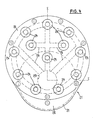
- the structure of the suction head 21 and its connecting part 22 is shown in more detail in FIGS. 4 and 5.
- the suction head has a circular ring of suction nozzles 24, which are inserted into a circular plate 25. They have outer, exposed, precisely machined end faces which are suitable for abutment or for firm suction on the freely accessible opposite end face of the rod 9, as indicated in FIGS. 1 and 2.
- the bores of the suction nozzles 24 are connected to vacuum channels 26 milled into the plate 28, which are sealed by a sealing plate 27 lying between the plate 25 and the plate 28. All vacuum channels 26 are directly or indirectly connected to the axial bore 29 of a sleeve-like clamping piston 30.
- the plate 28 is firmly screwed to a mounting plate 31 with a spherical bearing surface 32 which bears against a conical bearing surface 33 of a housing part 34.
- the housing part 34 is tightly and firmly connected to the connecting part 22.
- a clamping ring 35 with a spherical clamping surface 36 is fastened on the clamping piston 30.
- a spherically curved, flat coupling part 38 is inserted, which engages in one plane (FIG. 5 above) with pins 39a in grooves 40a of the mounting plate 31 while it is in the other plane (Fig. 5 below) engages with corresponding pins 39b in grooves 40b of the clamping ring 35.
- a gimbal locking device or coupling between the clamping ring 35 and the mounting plate 31 is thus achieved.
- the clamping ring 35 is held in a certain orientation on the clamping piston 30 by means of insert spring wedges 35a, and the opposite end of the clamping piston 30 is secured against rotation by means of a groove 42 and a pin 42a of the connecting part 22.
- pressure medium can be let into the space 44 between the housing part 34 and the thickened end of the clamping piston 30, which acts as a piston, in order to exert a force directed to the right in FIG. 5.
- a vacuum can be generated in the channel 29 through a further inlet 45 and in the suction nozzles 24 through the channels 26.
- a sealing sleeve 41 is inserted between the clamping ring 35 and the plate 28, which prevents loss of vacuum.
- a dirt-proof seal 36 which is as soft as possible, is arranged between the mounting plate 31 and the housing part 34.
- the mounting plate 31 and the housing part 34 with their spherical or conical surfaces 32 and 33 form a ball joint between the fixed parts 22 and 34 and the suction head 21.
- the pressure chamber 44 is depressurized and the clamping piston 30 is in the rest position is located on the far left, so that the suction head 21 can pivot with little resistance being overcome. If he is pressed against the end face of the rod 9, the ring of suction nozzles 24 fits snugly against the end face of the rod 9 and the suction head 21 is thus oriented exactly according to the end face.
- the pressure of the lower suction nozzles 24 is higher than the pressure of the upper suction nozzles because the pressure force acts below the center of the ring of suction nozzles, and this is desirable if the suction head is pressed on only when, according to FIG. 2, there is already a certain depth of cut is reached.
- the arm 23, which carries the suction head 21, is attached to a vertical slide 50.
- This vertical slide can be adjusted vertically on a horizontal slide 52 by means of a spindle which can be actuated by handwheel 51 and can be fixed at the desired height by means of clamping lever 53.
- the horizontal slide 52 is horizontally displaceable on rods 54. The horizontal displacement is carried out by a spindle 55 which can be driven by a motor 57 in both directions of rotation via a toothed belt 56.
- a sheet 59 is arranged in the direction of displacement of the horizontal slide 52, with which the piston rod 60 of a clamping cylinder 61 can work together around the Hori to block the central slide in an reached working position.
- the nut cooperating with the spindle 55 is designed as a piston 47 in a cylinder bore.
- a pressure medium can be introduced into the annular space 48 between the further sealing end of the piston 47 and the inner annular cylinder wall, which seeks to shift the horizontal slide 52 relative to the piston or the spindle nut 47 to the left in FIG. 2, and thus the suction head 21 with a certain force, but elastic and resilient, allowed to press against the end face of the rod 9, when the spindle nut 47 is shifted to the right in FIG. 2, the horizontal slide 52 and the parts connected to it via a stop ring 49, a coil spring 62 and one with the Carriage 63 connected to the horizontal carriage taken to the right in FIG. 2.
- An elastic connection thus acts in both directions, which allows a certain overflow of the spindle nut or the piston 47 beyond a stop position.
- the guide rods 54 and the guides slidable thereon and the mechanism of the horizontal slide are protected by the guide bed 58 and a bellows 64 each.
- the inlet 43 can be fed with pressure medium from a pressure medium booster 65.
- this pressure medium booster can either be pressurized with pressure medium from a supply line 67 via a reversing valve 66 or can be separated from the pressure medium source. If the pressure on the high pressure side, that is to say at the inlet 43, reaches the operating pressure, a pressure switch 68 is actuated tigt and delivers a confirmation signal via a line 69.
- the clamping cylinder 61 can also be fed via a pressure booster 70, to which a pressure switch 71 is also connected on the high pressure side and can transmit a confirmation signal via a line 72 if the operating pressure is present or is absent.
- the control takes place via a reversing valve 73.
- the pressure medium is supplied to the cylinder space 48 via an adjustable pressure regulator 74 and a reversing valve 84.
- a reversible, pneumatic cylinder 75 is also provided, which allows a rack 76 to be brought into one or the other end position.
- the control takes place via a reversing valve 77.
- the toothed rack 76 meshes with a toothed wheel 78 which is coupled to the movable part 23a of the arm carrying the suction head 21.
- the arm part 23 with the suction head 21 can be pivoted away from an operating position into an effective position in order to make room for another removal device, not shown, which can be used, for example, to cut larger sections remove and discharge.
- Detectors 80 and 81 cooperate with a control segment 79 on the gear 78 in order to transmit confirmation signals via lines 82 and 83 about the position of the part 23a and the suction head.
- FIG. 1 shows the state during the cutting process.
- the cutting disc 12 has penetrated approximately half of the rod 9.
- the suction head 21 is sucked onto the end face of the rod 9 or an already partially cut-out disk 9a.
- the pressure chamber 44 is under pressure via the valve 66 and the pressure booster 65, so that the clamping piston 30 is pressed to the right in FIG. 5.
- This will over the pressure ring 35 also the plate 31 with its spherical surface 32 pressed against the conical surface 33 of the housing part 34, and the suction head 21 is thus rigidly connected to the connecting part 22 and the arm 23 in an unambiguous position.
- the removal device remains in this position until the disk 9a is completely separated from the rod 9. At the moment of severing, practically no forces act on the severed disc 9a, and there is also no relative displacement between this disc or the suction head 21 and the rod 9, because these parts are in rigid mutual connection via the machine stand 1 by the cutting feed rate Cutting disc 12 is generated by pivoting the rocker 15. There is thus a clean cut with flat cut surfaces, both on the rod 9 and on the disc 9a.
- the rod 9 can be withdrawn by means of the carriage 11; likewise, the disc 9a is withdrawn by reversing the valve 73 and thus putting the pressure booster 70 and consequently also the cylinder 61 under pressure.
- the clamping piston 60 is thus lifted off the flag 59 and gives the horizontal slide 52 for the Withdrawal movement free.
- the prestressed compression spring 62 By means of the prestressed compression spring 62, the slide 52 and thus the suction head with the disk 92 are withdrawn by a small amount.
- the rocker 15 with the cutting disc 12 is then returned to the starting position, the cutting disc 12 being raised completely out of the area of the rod 9.
- the horizontal slide 52 with the arm 23, the suction cup 21 and the previously separated disk 9a is moved to the right in FIGS. 1 and 2 by driving the spindle 55 into a position determined by a stop switch, not shown.
- the position of the horizontal slide 52 is determined here by a mechanical stop, and a possible further running of the spindle or the spindle nut 49 is made possible here thanks to the spring 62, which is compressed by the somewhat further running spindle.
- the disk 9a is taken over in a known manner, not shown, and then the vacuum in the suction head 21 is released, so that the disk 9a can be taken over.
- the part 23a with the suction nozzle 21 can also be pivoted into a take-over position by means of the cylinder 75, but this pivoting is rather intended for the above-mentioned purpose, namely to make room for another removal device.
- the spindle 5 is driven in the opposite direction in order to return the horizontal slide 52 to the working position shown in FIGS. 1 and 2.
- the rod 9 has been shifted to the right by a partial step in FIG. 2 by means of the feed carriage 11, so that the free front end face of the rod 9 now lies in the foremost plane of the rod or the disk 9a shown in FIG.
- a new pane of any thickness can be separated.
- FIG the pressure chamber 48 let in pressure by reversing the valve 84 so that the spindle nut 47 takes the horizontal slide with it to a certain extent via the compression spring in the chamber 60.
- the pressure in the pressure chamber 48 determines the pressure of the suction head 21 against the end face of the rod 9.
- the valve 66 is reversed, so that the pressure booster 65 and the pressure chamber 44 are depressurized.
- the clamping piston 30 thus releases the pressure ring 35, so that the clamping of the plate 31 against the housing part 34 is released and the suction head 21 is freely movable.
- the pressure of the suction head 21 against the rod 9 is determined here by the pressure in the pressure chamber 48, and a possible overflow of the spindle nut 59 over a fixed stop position of the horizontal slide 52 remains meaningless because the pressure chamber 48 acts as a pneumatic spring, so to speak, which overflows it permitted without the pressure of the suction head 21 being influenced thereby.
- the suction head 21 is evacuated so that it sucks onto the end face of the rod 9. Then the valve 66 is reversed again, whereby the ball joint between the suction head 21 and its carrier is blocked in the manner mentioned by pressing the plate 31 against the housing part 34. The valve 84 is then reversed to release the pressure from the chamber 48. As mentioned, the horizontal slide 52 thus moves into a position in which pressures and deformations are eliminated. The blocking of the ball joint between the suction head 21 and the connecting part 22 or the arm 234 may also first done now. Then the horizontal slide 52 is blocked again by reversing the valve 3 in its working position. In the meantime, the cutting process has already started or is starting now. The initial state shown has thus been reached.
- connection part 22 which carries the suction head 21
- connection part 22 Due to the type of attachment of the connection part 22, which carries the suction head 21, it is possible to exchange the suction head 21 with the ball joint and connection part 22, e.g. against a suction head without ball joint.
Landscapes
- Engineering & Computer Science (AREA)
- Mechanical Engineering (AREA)
- Mechanical Treatment Of Semiconductor (AREA)
- Processing Of Stones Or Stones Resemblance Materials (AREA)
- Finish Polishing, Edge Sharpening, And Grinding By Specific Grinding Devices (AREA)
- Jigs For Machine Tools (AREA)
Priority Applications (4)
| Application Number | Priority Date | Filing Date | Title |
|---|---|---|---|
| EP86810177A EP0242489B1 (fr) | 1986-04-17 | 1986-04-17 | Procédé pour couper une barre en segments, machine à couper par meulage mettant en oeuvre le procédé et l'utilisation de cette machine |
| DE8686810177T DE3680205D1 (de) | 1986-04-17 | 1986-04-17 | Verfahren zum trennen eines stabes in teilstuecke, trennschleifmaschine zur durchfuehrung dieses verfahrens und verwendung dieser trennschleifmaschine. |
| US07/038,729 US4771759A (en) | 1986-04-17 | 1987-04-15 | Method for severing a rod in slices, slicing machine for carrying out the method and use of the slicing machine |
| JP62091106A JPS6316937A (ja) | 1986-04-17 | 1987-04-15 | ロツドをスライスに切断する方法、その方法を実施するためのスライシング加工機、およびその使用 |
Applications Claiming Priority (1)
| Application Number | Priority Date | Filing Date | Title |
|---|---|---|---|
| EP86810177A EP0242489B1 (fr) | 1986-04-17 | 1986-04-17 | Procédé pour couper une barre en segments, machine à couper par meulage mettant en oeuvre le procédé et l'utilisation de cette machine |
Publications (2)
| Publication Number | Publication Date |
|---|---|
| EP0242489A1 true EP0242489A1 (fr) | 1987-10-28 |
| EP0242489B1 EP0242489B1 (fr) | 1991-07-10 |
Family
ID=8196459
Family Applications (1)
| Application Number | Title | Priority Date | Filing Date |
|---|---|---|---|
| EP86810177A Expired - Lifetime EP0242489B1 (fr) | 1986-04-17 | 1986-04-17 | Procédé pour couper une barre en segments, machine à couper par meulage mettant en oeuvre le procédé et l'utilisation de cette machine |
Country Status (4)
| Country | Link |
|---|---|
| US (1) | US4771759A (fr) |
| EP (1) | EP0242489B1 (fr) |
| JP (1) | JPS6316937A (fr) |
| DE (1) | DE3680205D1 (fr) |
Cited By (7)
| Publication number | Priority date | Publication date | Assignee | Title |
|---|---|---|---|---|
| FR2622820A1 (fr) * | 1987-11-05 | 1989-05-12 | Mueller Georg Nuernberg | Procede et dispositif de fabrication de pastilles presentant au moins une surface plane |
| EP0410362A1 (fr) * | 1989-07-26 | 1991-01-30 | I.B. Rathscheck Söhne Kg | Dispositif pour tailler des plaques |
| EP0459544A2 (fr) * | 1990-04-27 | 1991-12-04 | Koninklijke Philips Electronics N.V. | Machine-outil avec dispositif de positionnement coulissant |
| DE10128630A1 (de) * | 2001-06-13 | 2003-01-02 | Freiberger Compound Mat Gmbh | Vorrichtung und Verfahren zur Bestimmung der Orientierung einer kristallografischen Ebene relativ zu einer Kristalloberfläche sowie Vorrichtung und Verfahren zum Trennen eines Einkristalls in einer Trennmaschine |
| CN106626116A (zh) * | 2016-10-12 | 2017-05-10 | 王淙可 | 一种棒料自动送料机构 |
| CN111730771A (zh) * | 2020-06-09 | 2020-10-02 | 安徽利锋机械科技有限公司 | 一种晶圆切割机 |
| CN113119332A (zh) * | 2021-04-27 | 2021-07-16 | 曲靖阳光能源硅材料有限公司 | 一种硅棒开方装置及方法 |
Families Citing this family (11)
| Publication number | Priority date | Publication date | Assignee | Title |
|---|---|---|---|---|
| US4903681A (en) * | 1987-02-24 | 1990-02-27 | Tokyo Seimitus Co., Ltd. | Method and apparatus for cutting a cylindrical material |
| US4899719A (en) * | 1987-07-31 | 1990-02-13 | Mitsubishi Kinsoku Kabushiki Kaisha | Apparatus for collecting wafers |
| US5240882A (en) * | 1988-06-28 | 1993-08-31 | Naoetsu Electronics Co. | Process and apparatus for making discrete type substrates by re-slicing a wafer |
| DE3906091A1 (de) * | 1989-02-27 | 1990-08-30 | Wacker Chemitronic | Verfahren zum zersaegen von stabfoermigen werkstuecken in scheiben mittels innenlochsaege, sowie innenlochsaegen zu seiner durchfuehrung |
| US4974578A (en) * | 1989-08-17 | 1990-12-04 | Silicon Technology Corporation | Housing for mounting a spindle of an internal diameter saw blade |
| JPH0695504B2 (ja) * | 1989-10-31 | 1994-11-24 | 直江津電子工業株式会社 | ウエハ枚葉式内周刃2分割切断装置におけるウエハ供給回収装置 |
| JPH1022244A (ja) * | 1996-06-29 | 1998-01-23 | Komatsu Electron Metals Co Ltd | 半導体ウェハの洗浄用バスケット |
| DE19905750B4 (de) * | 1999-02-11 | 2005-07-21 | Siltronic Ag | Innenlochsäge und Verfahren zum Schutz der Spannkante und zur Reinigung des Sägeblatts einer Innenlochsäge |
| DE102009047027B3 (de) * | 2009-11-23 | 2011-07-28 | J. Schmalz GmbH, 72293 | Vorrichtung zum Herstellen von Materialscheiben |
| CN113799276A (zh) * | 2020-06-15 | 2021-12-17 | 天通日进精密技术有限公司 | 硅棒装卸装置及硅棒开方设备 |
| CN111673167B (zh) * | 2020-06-29 | 2021-11-12 | 安徽福瑞尔铝业科技有限公司 | 一种仿木纹铝单板裁切用定位机构及方法 |
Citations (4)
| Publication number | Priority date | Publication date | Assignee | Title |
|---|---|---|---|---|
| DE1646147A1 (de) * | 1967-05-13 | 1971-01-07 | Telefunken Patent | Vorrichtung zur Halterung einer Halbleiterscheibe bei der UEbertragung eines Musters durch Kontaktkopie oder durch Projektionsmaskierung |
| US3969004A (en) * | 1974-08-02 | 1976-07-13 | The Computervision Corporation | Air bearing piston assembly for semiconductor mask-to-wafer aligner |
| FR2360488A1 (fr) * | 1976-08-02 | 1978-03-03 | Philips Nv | Dispositif pour l'enlevement de plaques |
| EP0079744A2 (fr) * | 1981-11-10 | 1983-05-25 | Silicon Technology Corporation | Assemblage de support pour enlever une plaquette semi-conductrice d'un lingot |
Family Cites Families (5)
| Publication number | Priority date | Publication date | Assignee | Title |
|---|---|---|---|---|
| US3577861A (en) * | 1969-04-07 | 1971-05-11 | Kayex Corp | Transfer device for cutting apparatus |
| US3833230A (en) * | 1973-09-13 | 1974-09-03 | Corning Glass Works | Vacuum chuck |
| US4116095A (en) * | 1977-08-05 | 1978-09-26 | Cousino Walter F | Metal sawing or milling machine |
| FR2412385A1 (fr) * | 1977-12-22 | 1979-07-20 | Crouzet Sa | Machine a scier des barreaux de silicium |
| SU1079373A1 (ru) * | 1983-02-04 | 1984-03-15 | Предприятие П/Я В-2265 | Вакуумный патрон |
-
1986
- 1986-04-17 EP EP86810177A patent/EP0242489B1/fr not_active Expired - Lifetime
- 1986-04-17 DE DE8686810177T patent/DE3680205D1/de not_active Expired - Lifetime
-
1987
- 1987-04-15 JP JP62091106A patent/JPS6316937A/ja active Pending
- 1987-04-15 US US07/038,729 patent/US4771759A/en not_active Expired - Fee Related
Patent Citations (4)
| Publication number | Priority date | Publication date | Assignee | Title |
|---|---|---|---|---|
| DE1646147A1 (de) * | 1967-05-13 | 1971-01-07 | Telefunken Patent | Vorrichtung zur Halterung einer Halbleiterscheibe bei der UEbertragung eines Musters durch Kontaktkopie oder durch Projektionsmaskierung |
| US3969004A (en) * | 1974-08-02 | 1976-07-13 | The Computervision Corporation | Air bearing piston assembly for semiconductor mask-to-wafer aligner |
| FR2360488A1 (fr) * | 1976-08-02 | 1978-03-03 | Philips Nv | Dispositif pour l'enlevement de plaques |
| EP0079744A2 (fr) * | 1981-11-10 | 1983-05-25 | Silicon Technology Corporation | Assemblage de support pour enlever une plaquette semi-conductrice d'un lingot |
Cited By (11)
| Publication number | Priority date | Publication date | Assignee | Title |
|---|---|---|---|---|
| FR2622820A1 (fr) * | 1987-11-05 | 1989-05-12 | Mueller Georg Nuernberg | Procede et dispositif de fabrication de pastilles presentant au moins une surface plane |
| EP0410362A1 (fr) * | 1989-07-26 | 1991-01-30 | I.B. Rathscheck Söhne Kg | Dispositif pour tailler des plaques |
| EP0459544A2 (fr) * | 1990-04-27 | 1991-12-04 | Koninklijke Philips Electronics N.V. | Machine-outil avec dispositif de positionnement coulissant |
| EP0459544A3 (en) * | 1990-04-27 | 1992-07-08 | Koninkl Philips Electronics Nv | Machine tool with movable positioning device |
| DE10128630A1 (de) * | 2001-06-13 | 2003-01-02 | Freiberger Compound Mat Gmbh | Vorrichtung und Verfahren zur Bestimmung der Orientierung einer kristallografischen Ebene relativ zu einer Kristalloberfläche sowie Vorrichtung und Verfahren zum Trennen eines Einkristalls in einer Trennmaschine |
| US6923171B2 (en) | 2001-06-13 | 2005-08-02 | Freiberger Compound Materials Gmbh | Device and method for determining the orientation of a crystallographic plane in relation to a crystal surface and device for cutting a single crystal in a cutting machine |
| CN106626116A (zh) * | 2016-10-12 | 2017-05-10 | 王淙可 | 一种棒料自动送料机构 |
| CN106626116B (zh) * | 2016-10-12 | 2018-05-29 | 王淙可 | 一种棒料自动送料机构 |
| CN111730771A (zh) * | 2020-06-09 | 2020-10-02 | 安徽利锋机械科技有限公司 | 一种晶圆切割机 |
| CN113119332A (zh) * | 2021-04-27 | 2021-07-16 | 曲靖阳光能源硅材料有限公司 | 一种硅棒开方装置及方法 |
| CN113119332B (zh) * | 2021-04-27 | 2022-04-08 | 曲靖阳光新能源股份有限公司 | 一种硅棒开方装置 |
Also Published As
| Publication number | Publication date |
|---|---|
| JPS6316937A (ja) | 1988-01-23 |
| DE3680205D1 (de) | 1991-08-14 |
| EP0242489B1 (fr) | 1991-07-10 |
| US4771759A (en) | 1988-09-20 |
Similar Documents
| Publication | Publication Date | Title |
|---|---|---|
| EP0242489B1 (fr) | Procédé pour couper une barre en segments, machine à couper par meulage mettant en oeuvre le procédé et l'utilisation de cette machine | |
| DE3318653C2 (de) | Vorrichtung zum Zuschneiden von Zuschnittmaterial aus Stoff oder dgl. | |
| EP3446816B1 (fr) | Mandrin de serrage pour roues | |
| DE2159580A1 (de) | Bandsaegemaschine | |
| DE69101663T2 (de) | Ventilkopf-Schleifgerät, insbesondere für einen Verbrennungsmotor. | |
| DE4337902C2 (de) | Stanze für Bahnmaterial | |
| EP1679145B1 (fr) | Scie à ruban à métaux avec cadre de scie suspendu | |
| DE2355339B2 (de) | Präzisionshaltevorrichtung für zylindrische Werkstücke | |
| DE3701446C2 (de) | Innenrundschleifmaschine | |
| DE69909977T2 (de) | Vorrichtung zum Stumpf-Laserschweissen von Blechen (vorbestimmten Zuschnitten), die magnetische Rollen hat um die Bleche nach der Schweissposition zu bewegen und die aktive Klemmen hat, um die Bleche zu klemmen | |
| DE2654934B2 (de) | Vorrichtung zum mechanischen Abtragen und Beseitigen von Flecken und Anrissen auf der Oberfläche von Walzknüppeln | |
| DE1502929A1 (de) | Blechschere | |
| DE7729113U1 (de) | Vorrichtung zum abkanten von reifenschichten | |
| DE3320283A1 (de) | Verfahren zum schneiden und vorrichtung zum steuern des saegebandvorschubes bei bandsaegemaschinen | |
| DE2320218A1 (de) | Vorrichtung zum schneiden von bahnmaterial | |
| DE1286379B (de) | Brammen-Fraesmaschine | |
| DE102008043652B3 (de) | Werkzeughalter für Werkzeugmaschinen und Verfahren zu seinem Betreiben | |
| DE2838656A1 (de) | Kreissaege mit schnittspaltoeffnung | |
| DE10057228B4 (de) | Verfahren zum Schleifen von optischen Linsen mittels Ring- und Formwerkzeugen und Vorrichtung zur Durchführung des Verfahrens | |
| DE2452233A1 (de) | Konturenschleifmaschine | |
| DE3113396C2 (fr) | ||
| DD263944A1 (de) | Vorrichtung zur oberflaechen- und wasserrinnenbearbeitung von kleinteilen aus stein oder steinaehnlichem werkstoff | |
| DE889856C (de) | Spannfutter fuer Drehbaenke od. dgl. | |
| CH642293A5 (en) | Work-holding and work-feeding fixture for machine tools | |
| DE1427489C (de) | Schleifmaschine zum Schleifen der Messer eines an einem Teilkopf festgespann ten Messerkopfes |
Legal Events
| Date | Code | Title | Description |
|---|---|---|---|
| PUAI | Public reference made under article 153(3) epc to a published international application that has entered the european phase |
Free format text: ORIGINAL CODE: 0009012 |
|
| AK | Designated contracting states |
Kind code of ref document: A1 Designated state(s): AT BE CH DE FR GB IT LI LU NL SE |
|
| RBV | Designated contracting states (corrected) |
Designated state(s): CH DE FR GB IT LI NL |
|
| 17P | Request for examination filed |
Effective date: 19880408 |
|
| 17Q | First examination report despatched |
Effective date: 19890419 |
|
| GRAA | (expected) grant |
Free format text: ORIGINAL CODE: 0009210 |
|
| ITF | It: translation for a ep patent filed | ||
| AK | Designated contracting states |
Kind code of ref document: B1 Designated state(s): CH DE FR GB IT LI NL |
|
| REF | Corresponds to: |
Ref document number: 3680205 Country of ref document: DE Date of ref document: 19910814 |
|
| GBT | Gb: translation of ep patent filed (gb section 77(6)(a)/1977) | ||
| ET | Fr: translation filed | ||
| PLBE | No opposition filed within time limit |
Free format text: ORIGINAL CODE: 0009261 |
|
| STAA | Information on the status of an ep patent application or granted ep patent |
Free format text: STATUS: NO OPPOSITION FILED WITHIN TIME LIMIT |
|
| 26N | No opposition filed | ||
| PGFP | Annual fee paid to national office [announced via postgrant information from national office to epo] |
Ref country code: GB Payment date: 19930315 Year of fee payment: 8 |
|
| PGFP | Annual fee paid to national office [announced via postgrant information from national office to epo] |
Ref country code: FR Payment date: 19930322 Year of fee payment: 8 |
|
| PGFP | Annual fee paid to national office [announced via postgrant information from national office to epo] |
Ref country code: CH Payment date: 19930423 Year of fee payment: 8 |
|
| PGFP | Annual fee paid to national office [announced via postgrant information from national office to epo] |
Ref country code: NL Payment date: 19930430 Year of fee payment: 8 |
|
| PGFP | Annual fee paid to national office [announced via postgrant information from national office to epo] |
Ref country code: DE Payment date: 19930630 Year of fee payment: 8 |
|
| PG25 | Lapsed in a contracting state [announced via postgrant information from national office to epo] |
Ref country code: GB Effective date: 19940417 |
|
| PG25 | Lapsed in a contracting state [announced via postgrant information from national office to epo] |
Ref country code: LI Effective date: 19940430 Ref country code: CH Effective date: 19940430 |
|
| PG25 | Lapsed in a contracting state [announced via postgrant information from national office to epo] |
Ref country code: NL Effective date: 19941101 |
|
| GBPC | Gb: european patent ceased through non-payment of renewal fee |
Effective date: 19940417 |
|
| NLV4 | Nl: lapsed or anulled due to non-payment of the annual fee | ||
| PG25 | Lapsed in a contracting state [announced via postgrant information from national office to epo] |
Ref country code: FR Effective date: 19941229 |
|
| REG | Reference to a national code |
Ref country code: CH Ref legal event code: PL |
|
| PG25 | Lapsed in a contracting state [announced via postgrant information from national office to epo] |
Ref country code: DE Effective date: 19950103 |
|
| REG | Reference to a national code |
Ref country code: FR Ref legal event code: ST |
|
| PG25 | Lapsed in a contracting state [announced via postgrant information from national office to epo] |
Ref country code: IT Free format text: LAPSE BECAUSE OF NON-PAYMENT OF DUE FEES;WARNING: LAPSES OF ITALIAN PATENTS WITH EFFECTIVE DATE BEFORE 2007 MAY HAVE OCCURRED AT ANY TIME BEFORE 2007. THE CORRECT EFFECTIVE DATE MAY BE DIFFERENT FROM THE ONE RECORDED. Effective date: 20050417 |