EP0410362A1 - Dispositif pour tailler des plaques - Google Patents
Dispositif pour tailler des plaques Download PDFInfo
- Publication number
- EP0410362A1 EP0410362A1 EP90114118A EP90114118A EP0410362A1 EP 0410362 A1 EP0410362 A1 EP 0410362A1 EP 90114118 A EP90114118 A EP 90114118A EP 90114118 A EP90114118 A EP 90114118A EP 0410362 A1 EP0410362 A1 EP 0410362A1
- Authority
- EP
- European Patent Office
- Prior art keywords
- raw
- plate
- dressing
- abutment
- clamping
- Prior art date
- Legal status (The legal status is an assumption and is not a legal conclusion. Google has not performed a legal analysis and makes no representation as to the accuracy of the status listed.)
- Granted
Links
Images


Classifications
-
- B—PERFORMING OPERATIONS; TRANSPORTING
- B28—WORKING CEMENT, CLAY, OR STONE
- B28D—WORKING STONE OR STONE-LIKE MATERIALS
- B28D7/00—Accessories specially adapted for use with machines or devices of the preceding groups
- B28D7/04—Accessories specially adapted for use with machines or devices of the preceding groups for supporting or holding work or conveying or discharging work
-
- B—PERFORMING OPERATIONS; TRANSPORTING
- B21—MECHANICAL METAL-WORKING WITHOUT ESSENTIALLY REMOVING MATERIAL; PUNCHING METAL
- B21D—WORKING OR PROCESSING OF SHEET METAL OR METAL TUBES, RODS OR PROFILES WITHOUT ESSENTIALLY REMOVING MATERIAL; PUNCHING METAL
- B21D43/00—Feeding, positioning or storing devices combined with, or arranged in, or specially adapted for use in connection with, apparatus for working or processing sheet metal, metal tubes or metal profiles; Associations therewith of cutting devices
- B21D43/20—Storage arrangements; Piling or unpiling
- B21D43/24—Devices for removing sheets from a stack
Definitions
- the invention relates to a method and an apparatus for dressing slabs, in particular made of slate, clay or other natural or artificial rocks.
- Slabs of natural or artificial stone such as slate, fired clay or fiber cement, which have different sizes and shapes and are overlapped on a base made of wood or other material, are often used to cover roofs and to clad house walls.
- the prepared raw panels are cut according to a template to the desired shapes, the parts of a raw panel projecting beyond the edge of the template being cut off or cut off with a knife.
- a knife especially with slate slabs or other slabs made of natural rocks, there is the problem of conveying, clamping and processing the slab in such a way that it does not break on its conveying path and during processing.
- a method for dressing plates is known (DE-OS 38 39 546 A1), in which the raw plates are fed upright in a stack on a feed device and one raw plate after the other with a previously processed edge upright in free fall into one below the dressing station arranged are thrown off, where they are clamped upright and their not yet trimmed edges are cut off by a processing tool, after which the trimmed finished plates, following their gravity, are directed onto a removal means.
- the object of the invention is to provide a method and an apparatus for dressing slabs of the type described in the introduction, with which a large number of raw slabs, in particular raw slate slabs, in the shortest possible time gently prepared, that is, can be cut to the desired shape and size at its edges, and at the same time there is the possibility of making holes in the plates, which are required for fastening the finished plates, without an additional operation.
- the flawless feeding of the plates to the dressing station is achieved with a method according to the invention in that the foremost raw plate of the stack of raw plates brought up on the feed device is removed with a transfer device which is sucked onto the raw plate by vacuum, brought over the dressing station and by removing the suction effect of the Transfer device is dropped onto a support device in the dressing station.
- Such a method ensures that only one raw plate can ever be brought over the insertion opening of the dressing station and initially aligned there in such a way that it is exactly perpendicular to the center of the clamping device of the dressing station. Since a special transfer device is used to remove and insert the raw plates into the dressing station, which then allows the aligned plate to fall freely into the dressing station, a high working speed can be achieved, which is not possible if the transfer device has a raw plate itself up to the dressing station leads and presents the clamping device.
- each raw plate in the dressing station is centered in height and laterally on the abutment, the outline of which corresponds to the outline of the finished plate and thus forms a template for the raw plates to be trimmed .
- the finished plate in the dressing station is shifted from its throw-in position to an ejection position.
- the raw plate can already be moved into an ejection plane parallel to the insertion plane when it is clamped to the abutment. It is then possible to throw the next raw plate to be machined into the dressing station as soon as the finished plate is ejected, or in any case immediately afterwards, since the plates are fed and removed in different, mutually offset levels.
- the raw panels can be perforated after they are clamped, for which a special mandrel stamp is provided, which at the same time supports the clamping action of the clamping jaw of the clamping device after the perforation process and ensures that the panel to be machined is securely held when dressing its outer peripheral edge.
- the support device for catching and supporting the raw panels thrown in upright is provided with two supporting elements arranged side by side in the direction of the raw panel level which are independent of one another in the direction of throw-in of the raw plate and each of which has end position damping.
- these are expediently mounted on pneumatic cylinders or pistons which have damping elements for cushioning the end position and, after the damping collection of a raw plate, can be raised together with the support elements and the raw plate in their desired clamping position.
- damping elements for cushioning the end position and, after the damping collection of a raw plate, can be raised together with the support elements and the raw plate in their desired clamping position.
- the support device For lateral centering of the raw plate, the support device has two mutually opposite alignment bars which can be pushed out or swung out of their alignment position so that they are not in the way when the raw plates are thrown into the dressing device.
- the abutment and / or the clamping device can be provided with a suction head for holding the finished plate, which holds the finished plate until the clamping device and the support device have retracted and the ejection gap for throwing the plate in the ejection level has become clear.
- the clamping device has a clamping jaw and a perforating device that can be pushed forward independently of it and provided with at least one mandrel. Furthermore, it is expedient if the support device for catching and supporting the raw plates can be moved back and forth in the direction of the abutment, so that the raw plate can already be brought into an ejection plane parallel to the throw-in plane when it is clamped to the abutment.
- At least one circular processing tool is provided which only moves forward and always returns on a circular path to the dressing station, where it travels over the clamped raw plate and over it the abutment cuts off protruding edges.
- the processing tool can circle on a circular or Egyptian path and be guided on one or more rails.
- the processing tool is fastened to a support arm which rotates about a central axis arranged at a distance from the dressing station. The raw plates are then trimmed by a rotating processing tool.
- the machining tool circles around a substantially vertical central axis and is arranged in the turning circle of the machining tool of several dressing stations with essentially vertical abutments and clamping devices.
- the processing tool several, in Direction of movement arranged one behind the other partial knife, which form at least one partial ring of the type and size of the finished plate to be cut.
- the dividing knives are detachable and are attached radially to the central axis on a knife holder which circles around the central axis. The dividing knives can thus be easily adjusted and exchanged for those of a different shape and size.
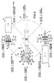
- 10 denotes a dressing device for dressing slate slabs, which consists of two processing stations I and II and a processing device III.
- the machining device III has a machining tool 11 which is fastened to a support arm 12 which rotates about a substantially vertical central axis 13 and is rotatably driven by a drive, not shown, so that the machining tool 11 is in a circular movement path 14 about the central axis 13 circles.
- the two processing stations I and II of identical design are arranged diametrically opposite one another, as is shown in FIGS. 4 and 5.
- Each of the two processing stations I and II consists of a dressing station 15, a raw plate feed device 16 arranged above the dressing station and a finished plate removal device 17 arranged below the dressing station.
- the arrangement is such that the support arm 12 of the processing device III is located at a height between the dressing devices 15 and the raw plate feeders 16, as shown in Fig. 1.
- the raw plate feed device 16 consists of a longitudinal conveyor device 18, which has a conveyor belt 19 rotating around belt rollers 20, on which a stack 21 of upright raw slab plates 22 made of slate is gradually advanced by a hydraulic or pneumatic feed device 23 against a transfer device 24.
- the transfer device 24 has a suction head 25 which is pivotally mounted in a carriage 26 about a horizontal axis 27 and by a first pneumatic cylinder about the Axis 27 pivoted and can be moved back and forth by a second pneumatic cylinder 29 against the raw plate stack 21 with the carriage 26.
- the suction head 25 has a suction plate, not shown here, with suction openings, behind which a negative pressure can be generated in order to hold a raw plate 22 in contact with the suction plate by suction and by lifting the suction through the gap 30 between the raw plate feed device 16 and the transfer device 24 to drop into the dressing station 15 below.
- Each dressing station 15 consists of a fixed abutment 31, a clamping device 32 that can be moved back and forth against the abutment and a support device 33 for a raw plate 22 arranged below the abutment 31 and clamping device 32.
- the abutment 31 has a vertically arranged abutment plate 34 in which a guide bar 36 which can be swung in and out of the front surface of the abutment plate by a third pneumatic cylinder 35 is arranged.
- the clamping device 32 arranged opposite the abutment 31 carries a perforating device 38 and a clamping jaw 37 which carries a rubber pressure plate 39 and can also be provided with a suction head which is similar to the suction head 25 of the transfer device 24.
- the perforating device 38 carries on it the Abutment plate 34 facing side mandrels 40, which penetrate the jaw 37 and can enter holes 41 provided for this purpose in the abutment plate 34 when they have pierced the raw plate 22 clamped between the abutment plate 34 and the jaw 37.
- the clamping jaw 37 can be pushed with the aid of a fourth pneumatic cylinder 41 in the direction of the abutment plate 34 via the perforating device 38 and pushed back against it.
- Hole device 38 and jaw 37 are carried by a bracket 42, which is on a support 43 is attached, which can be moved back and forth on a slide rail 44 by a fifth pneumatic cylinder 45 against the abutment 31.
- the support device 33 which consists of two support elements 47 and 48 arranged laterally next to one another in the direction of the plane of the raw plate 22 introduced into the dressing station 15, ie radially to the central axis 13 of the device, is also fastened to the support 43 with a support 46.
- Each of the two support elements 47 and 48 has a support plate 49 and 50, which is circular in the embodiment shown and is fastened on the piston rod 51 by sixth pneumatic cylinders 52. Every sixth pneumatic cylinder is provided with damping elements, not shown, which dampen the movement of the piston in the cylinder 52 before it reaches its end position. Such damping elements are known per se as "end position damping" in pneumatic cylinders and therefore do not need to be described in more detail here.
- the sixth pneumatic cylinders 52 are set in their initial position shown in FIG. 1 so that they yield elastically and act like shock absorbers when they are loaded by a raw plate 22 falling out of the gap 30, the two support elements 47 and 48 acting independently of one another. Both support plates 49 and 50 can then, together aligned horizontally at the same height, be raised together to the position shown in FIGS. 1, 2 and 3 in order to align the height of the raw plate 22 with the abutment plate 34.
- a guide device 53 is fastened, with which the prefabricated plates 54 falling out of the dressing station 15 are directed onto a conveying means 55, for example a belt conveyor belt, which ends at a stacking table 56 that can be raised and lowered.
- a pusher 57 is assigned to this stacking table 56, which pushes a stack 58 of finished plates formed onto a roller table 59 on which the Finished panels are conveyed to a storage location.
- the rotating machining tool 11 used to cut off the edges of the raw slate slabs has a frame-like knife carrier 60 with three holding rails 61, 62 and 63 arranged at a lateral distance from one another for four parting knives 64, 65, 66 and 67, which are equipped with knife holders 68, 69, 70 and 71 are adjustably fastened on the holding rails 61 to 63 in the longitudinal direction thereof.
- the holding rails 61 and 63 are arranged parallel to the central holding rail 62 which extends radially to the central axis 13 and that the four partial knives together form a partial ring in the circumferential direction (FIG. 1) which corresponds to the outline corresponds to the finished panels 54 to be cut apart from their previously machined lower edge 22a, with which they stand up on the support device when the panels are trimmed.
- the dressing stations 15 of the processing stations I and II are arranged in the movement path 14 of the processing tool 11 in such a way that the raw slate plates 22 clamped between the abutment 31 and the clamping device 32 of each dressing station are in a vertical position, are located approximately radially to the central axis 13 and that the raw plate feed devices 16 and the finished plate discharge devices 17 are connected tangentially to the movement path 14 above and below the dressing stations 15.
- centering devices 72 and 73 can also be seen, which are at a distance from one another and have alignment bars 74 with which the raw plates 22 in the dressing station 15 can be laterally centered on the abutment plate 34 in such a way that they are equally far above them on both sides survive.
- the alignment bars 74 can be pushed out of their alignment position shown in FIG. 5 with the aid of the centering devices, which may be pneumatic cylinders, for example withdrawn or swung out so that they are not in the way when inserting a raw plate.
- the raw plate 22 clamped between the abutment plate 34 of the abutment 31 and the clamping jaw 37 of the clamping device 32 is cut off at its upper and lateral edges when the dividing knives 64 to 67 slide over them .
- the abutment plate 34 serves as a template, the outer outline of which corresponds to the outline of the slate to be trimmed and slide over the knives of the machining tool 11 forming a partial ring, which surround the outer outline of the abutment plate 34 with little play.
- the processing station II While the processing station I is in its clamping position, the processing station II is in its open position, which is shown in FIG. 1 and in which a raw plate 22 is removed from the stack 21 and the space still open at the top is inserted between the abutment plate 34 and the clamping jaw 37 becomes.
- the suction head 25 of the transfer device 24 advances against the stack 21 and lies against the surface of the foremost raw plate 22 facing it, on which it is sucked by applying a vacuum.
- the suction head 25 then pivots back into the vertical position shown in FIG. 1 and moves into the ejection position shown in FIG. 1, in which it removes the raw plate by lifting the Suction in the suction head in the dressing station 15 drops.
- the raw plate 22 hits the support plates 49 and 50 of the support elements 47 and 48 in the dressing station, which yield elastically damped under the impact.
- both support elements can act individually one after the other if the raw plate 22 comes up crooked, i.e. with one of its two lower corners rather than with the other. The damping prevents the plate from jumping up again.
- both support plates 49 and 50 are brought to the same height and raised again to the position shown in FIG. 1.
- the processing tool 11 has reached position B.
- the perforating device 38 first moves back in the processing station I, as a result of which the mandrels 40 pull out of the abutment plate 34 and the perforated and trimmed finished plate 54, while the finished plate is still held between the abutment plate 34 and the jaw 37.
- the support device 33 also moves back, so that the space under the finished plate 54 becomes free.
- the clamping jaws and hole devices move together with the support device 33 into the clamping position, the guide bar 36 first being pivoted back into the surface of the abutment plate 34 after the raw plate 22 has previously been centered in the lateral direction by the centering devices 72 and 73.
- the clamping jaw 37 of the perforating device 38 leads so far that it pushes the raw plate 22 out of the first insertion plane 75 shown in FIG. 1 into the ejection plane 76 indicated in FIGS. 2 and 3, which is offset laterally with respect to the insertion plane is.
- the raw plate 22 is clamped by the clamping jaw 37 in the processing station II.
- the clamping device 32 moves back with the support device 33 into the starting position shown in FIG. 1, the guide bar 36 being simultaneously folded out of the abutment plate 34 so that an inserted raw plate is placed on the Support device is guided and does not slip.
- the punching device 38 now moves forward in the processing station II, the mandrels 40 first penetrating the clamping jaw 37 and then producing the desired holes in the raw plate 22 clamped between the clamping jaw 37 and the abutment plate 34.
- the perforating device 38 then lies behind the clamping jaw 37 and increases the clamping effect. This position is shown in Fig. 2.
- the invention is not limited to the exemplary embodiment shown and described, but that a number of changes and additions are possible without leaving the scope of the invention.
- more than two, for example four, processing stations could also be arranged in the path of movement of the processing tool.
- the raw plate feed devices and finished plate discharge devices could also be arranged radially to the path of movement of the processing tool.
- the way in which the raw plates are fed to the dressing stations is also possible in the case of machining tools with a different effect, for example in the case of tools which do not work in a circular manner but instead reciprocally.
- a plurality of circular processing tools can also be provided for processing the raw plates, which rotate in the same or in different movement paths and successively carry out different processing operations on the clamped raw plates, such as cutting and grinding the various edges of the raw plates.
Landscapes
- Engineering & Computer Science (AREA)
- Mechanical Engineering (AREA)
- Grinding-Machine Dressing And Accessory Apparatuses (AREA)
- Finish Polishing, Edge Sharpening, And Grinding By Specific Grinding Devices (AREA)
- Specific Conveyance Elements (AREA)
Applications Claiming Priority (2)
| Application Number | Priority Date | Filing Date | Title |
|---|---|---|---|
| DE3924616 | 1989-07-26 | ||
| DE3924616A DE3924616A1 (de) | 1989-07-26 | 1989-07-26 | Verfahren und vorrichtung zur zurichtung von platten |
Publications (2)
| Publication Number | Publication Date |
|---|---|
| EP0410362A1 true EP0410362A1 (fr) | 1991-01-30 |
| EP0410362B1 EP0410362B1 (fr) | 1993-02-10 |
Family
ID=6385806
Family Applications (1)
| Application Number | Title | Priority Date | Filing Date |
|---|---|---|---|
| EP90114118A Expired - Lifetime EP0410362B1 (fr) | 1989-07-26 | 1990-07-24 | Dispositif pour tailler des plaques |
Country Status (2)
| Country | Link |
|---|---|
| EP (1) | EP0410362B1 (fr) |
| DE (2) | DE3924616A1 (fr) |
Cited By (1)
| Publication number | Priority date | Publication date | Assignee | Title |
|---|---|---|---|---|
| CN107931475A (zh) * | 2017-11-15 | 2018-04-20 | 上海电机学院 | 一种止推片自动堆叠装置 |
Families Citing this family (1)
| Publication number | Priority date | Publication date | Assignee | Title |
|---|---|---|---|---|
| CN111673931B (zh) * | 2020-06-10 | 2022-05-27 | 浦江一本工贸有限公司 | 一种基于水晶切割的自动下料设备 |
Citations (3)
| Publication number | Priority date | Publication date | Assignee | Title |
|---|---|---|---|---|
| AT326295B (de) * | 1972-08-07 | 1975-12-10 | Saint Gobain | Vorrichtung zum verlagern einer polygonalen platte, insbesondere glasplatte |
| EP0242489A1 (fr) * | 1986-04-17 | 1987-10-28 | Maschinenfabrik Meyer & Burger AG | Procédé pour couper une barre en segments, machine à couper par meulage mettant en oeuvre le procédé et l'utilisation de cette machine |
| DE3839546A1 (de) * | 1987-12-24 | 1989-07-06 | Rathscheck J B Soehne | Schieferzurichtmaschine |
-
1989
- 1989-07-26 DE DE3924616A patent/DE3924616A1/de not_active Withdrawn
-
1990
- 1990-07-24 DE DE9090114118T patent/DE59000873D1/de not_active Expired - Fee Related
- 1990-07-24 EP EP90114118A patent/EP0410362B1/fr not_active Expired - Lifetime
Patent Citations (3)
| Publication number | Priority date | Publication date | Assignee | Title |
|---|---|---|---|---|
| AT326295B (de) * | 1972-08-07 | 1975-12-10 | Saint Gobain | Vorrichtung zum verlagern einer polygonalen platte, insbesondere glasplatte |
| EP0242489A1 (fr) * | 1986-04-17 | 1987-10-28 | Maschinenfabrik Meyer & Burger AG | Procédé pour couper une barre en segments, machine à couper par meulage mettant en oeuvre le procédé et l'utilisation de cette machine |
| DE3839546A1 (de) * | 1987-12-24 | 1989-07-06 | Rathscheck J B Soehne | Schieferzurichtmaschine |
Non-Patent Citations (1)
| Title |
|---|
| SOVIET INVENTIONS ILLUSTRA- TED, P,Q Sektionen, Woche 8637, 22. Oktober 1986 DERWENT PUBLICATIONS LTD., London, P 52 * SU - 1 207 585 ( ZAPORO ) * * |
Cited By (1)
| Publication number | Priority date | Publication date | Assignee | Title |
|---|---|---|---|---|
| CN107931475A (zh) * | 2017-11-15 | 2018-04-20 | 上海电机学院 | 一种止推片自动堆叠装置 |
Also Published As
| Publication number | Publication date |
|---|---|
| DE59000873D1 (de) | 1993-03-25 |
| DE3924616A1 (de) | 1991-01-31 |
| EP0410362B1 (fr) | 1993-02-10 |
Similar Documents
| Publication | Publication Date | Title |
|---|---|---|
| DE10114263C1 (de) | Verfahren und Vorrichtung zum Abtransport der mit einer Trennmaschine von stangenförmigem Werkstückmaterial abgetrennten Abschnitte | |
| EP3227072B1 (fr) | Équipement diviseur de panneaux pour diviser des pièces en forme de panneaux ainsi que son procédé de fonctionnement | |
| DE69602164T2 (de) | Automatische bohr- und fräsmaschine für glassplatten | |
| DE3911639A1 (de) | Verfahren und einrichtung zum programmgesteuerten laengs- und queraufteilen von werkstueckplatten | |
| DE3830857C1 (fr) | ||
| DE2614164C2 (fr) | ||
| DE3716666A1 (de) | Plattenaufteilanlage mit einer laengssaege und einer quersaege | |
| EP2886220A1 (fr) | Procédé de manipulation de plaques découpées au niveau d'une machine de découpe | |
| DE10157833B4 (de) | Vorrichtung zum Aufteilen einer Verbundglastafel in einzelne Verbundglasscheiben und Verfahren zum Positionieren einer Verbundglastafel auf einer Verbundglasschneidanlage | |
| EP0697940B1 (fr) | Dispositif, outil de serrage et procede de detachement de rognures lors du decoupage de pieces dans du carton | |
| DE3809146C2 (de) | Vorrichtung zum Zerteilen von Rollen von auf Dornen gewickelter band- oder folienförmiger Ware, insbesonders Papier | |
| EP0410362B1 (fr) | Dispositif pour tailler des plaques | |
| DE3830856C1 (fr) | ||
| DE19627946B4 (de) | Einrichtung zum Herstellen von flächigen Möbelteilen aus großen Platten | |
| EP1577273A2 (fr) | Dispositif et procédé pour couper du verre feuilleté selon un contour quelconque | |
| DE3312746C2 (fr) | ||
| EP0488143A1 (fr) | Méthode pour le meulage des surfaces de support d'articles en céramique | |
| DE69319518T2 (de) | Verfahren und Vorrichtung zum Zerschneiden von grossen Glasplatten in kleinere Abmessungen | |
| DE2150021C3 (de) | Anlegevorrichtung | |
| DE10261918B3 (de) | Vorrichtung zum exzentrischen Schneiden von Furnieren | |
| EP0017166B1 (fr) | Dispositif pour la subdivision automatique d'un panneau | |
| DE102021125391B4 (de) | Entstapelungsvorrichtung und Holzbearbeitungsanlage mit einer derartigen Entstapelungsvorrichtung | |
| DE1928820B1 (de) | Vorrichtung zum Bearbeiten von Tafelglas | |
| DE2321568A1 (de) | Kaltkreissaege | |
| EP0604702A1 (fr) | Dispositif pour trancher du bois équarri en planches |
Legal Events
| Date | Code | Title | Description |
|---|---|---|---|
| PUAI | Public reference made under article 153(3) epc to a published international application that has entered the european phase |
Free format text: ORIGINAL CODE: 0009012 |
|
| AK | Designated contracting states |
Kind code of ref document: A1 Designated state(s): BE DE ES FR GB LU |
|
| 17P | Request for examination filed |
Effective date: 19901222 |
|
| 17Q | First examination report despatched |
Effective date: 19911220 |
|
| RTI1 | Title (correction) | ||
| RTI1 | Title (correction) | ||
| RBV | Designated contracting states (corrected) |
Designated state(s): DE |
|
| GRAA | (expected) grant |
Free format text: ORIGINAL CODE: 0009210 |
|
| AK | Designated contracting states |
Kind code of ref document: B1 Designated state(s): DE |
|
| REF | Corresponds to: |
Ref document number: 59000873 Country of ref document: DE Date of ref document: 19930325 |
|
| PLBE | No opposition filed within time limit |
Free format text: ORIGINAL CODE: 0009261 |
|
| STAA | Information on the status of an ep patent application or granted ep patent |
Free format text: STATUS: NO OPPOSITION FILED WITHIN TIME LIMIT |
|
| 26N | No opposition filed | ||
| PGFP | Annual fee paid to national office [announced via postgrant information from national office to epo] |
Ref country code: DE Payment date: 19940627 Year of fee payment: 5 |
|
| PG25 | Lapsed in a contracting state [announced via postgrant information from national office to epo] |
Ref country code: DE Effective date: 19960402 |