EP0229961A2 - Antriebsvorrichtung für bewegliche Stoffabdeckungen - Google Patents
Antriebsvorrichtung für bewegliche Stoffabdeckungen Download PDFInfo
- Publication number
- EP0229961A2 EP0229961A2 EP86116974A EP86116974A EP0229961A2 EP 0229961 A2 EP0229961 A2 EP 0229961A2 EP 86116974 A EP86116974 A EP 86116974A EP 86116974 A EP86116974 A EP 86116974A EP 0229961 A2 EP0229961 A2 EP 0229961A2
- Authority
- EP
- European Patent Office
- Prior art keywords
- motor
- drive device
- profile
- tension
- shaft
- Prior art date
- Legal status (The legal status is an assumption and is not a legal conclusion. Google has not performed a legal analysis and makes no representation as to the accuracy of the status listed.)
- Granted
Links
Images
Classifications
-
- E—FIXED CONSTRUCTIONS
- E04—BUILDING
- E04F—FINISHING WORK ON BUILDINGS, e.g. STAIRS, FLOORS
- E04F10/00—Sunshades, e.g. Florentine blinds or jalousies; Outside screens; Awnings or baldachins
- E04F10/02—Sunshades, e.g. Florentine blinds or jalousies; Outside screens; Awnings or baldachins of flexible canopy materials, e.g. canvas ; Baldachins
- E04F10/06—Sunshades, e.g. Florentine blinds or jalousies; Outside screens; Awnings or baldachins of flexible canopy materials, e.g. canvas ; Baldachins comprising a roller-blind with means for holding the end away from a building
-
- E—FIXED CONSTRUCTIONS
- E06—DOORS, WINDOWS, SHUTTERS, OR ROLLER BLINDS IN GENERAL; LADDERS
- E06B—FIXED OR MOVABLE CLOSURES FOR OPENINGS IN BUILDINGS, VEHICLES, FENCES OR LIKE ENCLOSURES IN GENERAL, e.g. DOORS, WINDOWS, BLINDS, GATES
- E06B9/00—Screening or protective devices for wall or similar openings, with or without operating or securing mechanisms; Closures of similar construction
- E06B9/02—Shutters, movable grilles, or other safety closing devices, e.g. against burglary
- E06B9/08—Roll-type closures
- E06B9/11—Roller shutters
- E06B9/17—Parts or details of roller shutters, e.g. suspension devices, shutter boxes, wicket doors, ventilation openings
-
- E—FIXED CONSTRUCTIONS
- E06—DOORS, WINDOWS, SHUTTERS, OR ROLLER BLINDS IN GENERAL; LADDERS
- E06B—FIXED OR MOVABLE CLOSURES FOR OPENINGS IN BUILDINGS, VEHICLES, FENCES OR LIKE ENCLOSURES IN GENERAL, e.g. DOORS, WINDOWS, BLINDS, GATES
- E06B9/00—Screening or protective devices for wall or similar openings, with or without operating or securing mechanisms; Closures of similar construction
- E06B9/56—Operating, guiding or securing devices or arrangements for roll-type closures; Spring drums; Tape drums; Counterweighting arrangements therefor
- E06B9/68—Operating devices or mechanisms, e.g. with electric drive
- E06B9/72—Operating devices or mechanisms, e.g. with electric drive comprising an electric motor positioned inside the roller
-
- E—FIXED CONSTRUCTIONS
- E04—BUILDING
- E04F—FINISHING WORK ON BUILDINGS, e.g. STAIRS, FLOORS
- E04F10/00—Sunshades, e.g. Florentine blinds or jalousies; Outside screens; Awnings or baldachins
- E04F10/02—Sunshades, e.g. Florentine blinds or jalousies; Outside screens; Awnings or baldachins of flexible canopy materials, e.g. canvas ; Baldachins
- E04F10/06—Sunshades, e.g. Florentine blinds or jalousies; Outside screens; Awnings or baldachins of flexible canopy materials, e.g. canvas ; Baldachins comprising a roller-blind with means for holding the end away from a building
- E04F10/0607—Sunshades, e.g. Florentine blinds or jalousies; Outside screens; Awnings or baldachins of flexible canopy materials, e.g. canvas ; Baldachins comprising a roller-blind with means for holding the end away from a building with guiding-sections for supporting the movable end of the blind
Definitions
- the invention relates to a drive device for movable fabric covers for sun protection purposes, the fabric cover being arranged on a tubular winding shaft, that a motor-driven drive shaft is provided on which disks for a tension band are fastened on both sides, the winding shaft and the drive shaft being mechanically coupled to one another that Guide rails are provided on both sides, in which a pull rod fastened to the starting edge of the fabric cover is guided, to which the pulling band, which is in each case pulled over a deflection roller arranged at the extreme end of the guide rails, and is guided to the disc, is fastened.
- Such a drive device is known (for example DE-OS 3 147 827), in which the winding shaft and the drive shaft are arranged coaxially to one another and in this case the winding shaft is held in tension with respect to the drive shaft by means of a spring.
- the drive takes place via a motor housed in the drive shaft, which protrudes laterally, so that there is a protrusion in relation to the tension disc.
- This results in unfavorable connection options for a further section of such a fabric cover, ie the gaps between the individual fabric covers are relatively large in series systems.
- Another disadvantage is that the drawstring is partially freely running.
- the invention has for its object to design such a drive device so that a compact construction with concealed tape guide and tape winding can be achieved when arranging a profile for single and row systems.
- a symmetrical to a central mounting bracket profile is provided for the guide rail, which has on each side an open groove for a roller carriage of the tension rod and a closed guide chamber for the tension band that on the engine-side console a bracket is attached as an engine mount and that the engine-side traction disc is rotatably arranged above the bracket and the engine head.
- An advantageous embodiment provides that a motor bearing ring connected to the holder is provided on the motor head, on which a tubular section of the motor-side tension disc is arranged.
- the motor-side mounting bracket has a slot that extends approximately radially outward from the center.
- the guide chamber arranged in the profile has guide webs for the drawstring.
- the engine-side traction disc has bores and recesses in the area of the engine head for making adjustments and bearing attachments.
- console has an approximately tangential plug-in projection for insertion into the central profile chamber of the profile.
- the tension disc provided on the opposite side of the motor has an elongated hole running in the axial direction and can be fastened to the drive shaft.
- the suitable drive device for movable fabric covers for sun protection purposes with indoor or outdoor mounting for pergolas, winter gardens, flat-inclined shedo lights and glass domes, in which the fabrics do not roll by themselves but have to be transported by means of a pull rod has the main advantage that Drive mechanism is integrated in such a way that storage is possible with a distance of only two millimeters to an end bracket. This applies to both a one-sided and double-sided drive mechanism via electric tube motors.
- radii provided in the clockwise and counterclockwise directions can be provided with such material covers as desired.
- the winding shaft for the fabric is arranged coaxially to the drive shaft, there is only a small fabric gap between the belt guide in the profile and the fabric.
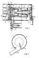
- a tubular winding shaft 1 for the material is arranged coaxially with a drive shaft 2.
- the two shafts 1, 2 are mechanically coupled to one another by a spring, not shown, which is held under prestress.
- a disk-shaped bracket 3 on both ends of the device, a U-shaped bracket 4, which serves as an engine mount, being fastened to the engine-side bracket 3.
- the motor head 5, to which a motor bearing ring 6 connects, is fastened to this holder 4.
- a tension disc 7 is arranged above the holder 4 and the motor head 5 and is rotatably arranged on the bearing ring 6.
- This disc 7 has, next to the bracket 3, a guide groove 8 for a tension band 9 and also a cylindrical support part 10 for better mounting on a connection to be provided with the drive shaft 2 Engine pipe.
- the tension disc 7 has bores and recesses in order to be able to make final adjustments to the internal motor head. Furthermore, it can also be used to secure bearings.
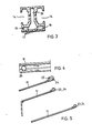
- the console 3 engages by means of a plug-in extension 25 in a self-supporting manner in a central profile chamber 26 of the symmetrically designed profile 11, which in each case forms the guide rail. This supports the entire drive mechanism with cladding.
- a belt 27 arranged on one or both sides serves for band steering.
- the console 3 has a radially outwardly extending slot 12 through which the connecting cable for the motor can be guided outwards, so that the width of the console 3 is simultaneously used for the discharge of the motor cable is used.
- the slot 12 begins approximately at the height of the center of the axis.
- the profile of the guide rails 11 has on both sides an open groove 14 for a roller carriage 15 and a closed guide chamber 16, in which the drawstring is guided. On the inside of this guide chamber 16 there are guide webs 17 which ensure better guidance of the drawstring in the chamber 16.
- the cloth 18 wound on the winding shaft 1 is fastened with its starting edge to a tension rod 19 which has the roller carriage 15 on the side. Furthermore, the tension band 9, starting from the tension band slide 7, is guided over a deflection roller 20 at the end of the guide rail 11 and fastened to the roller carriage 15.
- the tension disc 7 ⁇ arranged on the opposite side of the motor is designed differently than the motor-side disc 7. It has the guide groove 8 and a hub 22 for fastening on the shaft 2.
- the tension disc 7 ⁇ has in the region of its hub 22 arranged on the shaft 2 an elongated hole 21 and is thus slidable over the connecting axis in order to enable problem-free hanging of the axes in the bearings.
- the drive device is suitable for various drive systems, as is indicated, for example, in FIG. 5.
- the first embodiment shows two separate axes, namely an axis 23 for the fabric and an axis 24 for the drawstring.
- the two rollers are shown in a coaxial arrangement, the guide rail 11 initially running obliquely and then being guided steeply downward at a bend.
- the two axes are also arranged coaxially to one another and the guide track 11 runs uniformly obliquely downwards.
- a wide variety of drive systems such as tandem drive by means of a motor roller and spring roller, a tandem drive with two motor rollers or a drive as described in the exemplary embodiment according to FIG. 1 can be provided.
Landscapes
- Engineering & Computer Science (AREA)
- Architecture (AREA)
- Structural Engineering (AREA)
- Civil Engineering (AREA)
- Treatment Of Fiber Materials (AREA)
- Building Awnings And Sunshades (AREA)
- Operating, Guiding And Securing Of Roll- Type Closing Members (AREA)
- Yarns And Mechanical Finishing Of Yarns Or Ropes (AREA)
- Containers And Plastic Fillers For Packaging (AREA)
- Manufacturing Of Electric Cables (AREA)
- Knitting Machines (AREA)
Abstract
Description
- Die Erfindung betrifft eine Antriebsvorrichtung für bewegliche Stoffabdeckungen zu Sonnenschutzzwecken, wobei die Stoffabdeckung auf einer rohrförmigen Wickelwelle angeordnet ist, daß eine motorgetriebene Antriebswelle vorgesehen ist, an der beidseitig Scheiben für ein Zugband befestigt sind, wobei die Wickelwelle und die Antriebswelle mechanisch miteinander gekoppelt sind, daß beidseitig Führungsschienen vorgesehen sind, in denen ein an der Anfangskante der Stoffabdeckung befestigter Zugstab geführt ist, an dem das jeweils über eine am äußersten Ende der Führungsschienen angeordnete Umlenkrolle gezogene und zur Scheibe geführte Zugband befestigt ist.
- Eine derartige Antriebsvorrichtung ist bekannt (z.B. DE-OS 3 147 827), bei der die Wickelwelle und die Antriebswelle koaxial zueinander angeordnet sind und hierbei die Wickelwelle gegenüber der Antriebswelle mittels einer Feder auf Vorspannung gehalten wird. Der Antrieb erfolgt über einen in der Antriebswelle untergebrachten Motor, der seitlich herausragt, so daß ein Überstand gegenüber der Zugbandscheibe besteht. Dadurch ergeben sich ungünstige Anschlußmöglichkeiten für einen weiteren Abschnitt einer solchen Stoffabdeckung, d.h. bei Reihenanlagen sind die Lücken zwischen den einzelnen Stoffabdeckungen verhältnismäßig groß. Ein weiterer Nachteil besteht darin, daß das Zugband teilweise freilaufend angeordnet ist.
- Der Erfindung liegt die Aufgabe zugrunde, eine derartige Antriebsvorrichtung so auszubilden, daß bei Anordnung eines Profiles für Einzel- als auch Reihenanlagen eine gedrängte Bauweise mit verdeckter Bandführung und Bandwicklung erreichbar ist.
- Diese Aufgabe wird nach der Erfindung dadurch gelöst, daß ein symmetrisch zu einer mittleren Befestigungskonsole ausgebildetes Profil für die Führungsschiene vorgesehen ist, das an jeder Seite eine offene Nut für einen Rollenwagen des Zugstabes und eine geschlossene Führungskammer für das Zugband aufweist, daß an der motorseitigen Konsole eine Halterung als Motorlager angebracht ist und daß über der Halterung und dem Motorkopf die motorseitige Zugbandscheibe drehbar angeordnet ist.
- Eine vorteilhafte Ausführungsform sieht vor, daß am Motorkopf ein mit der Halterung verbundener Motorlagerring vorgesehen ist, auf dem ein rohrförmiger Abschnitt der motorseitigen Zugbandscheibe angeordnet ist.
- Weiterhin ist es vorteilhaft, daß die motorseitige Befestigungskonsole einen etwa von der Mitte radial nach außen verlaufenden Schlitz aufweist.
- Weiterhin wird vorgeschlagen, daß die in dem Profil angeordnete Führungskammer für das Zugband Führungsstege aufweist.
- Es ist weiterhin vorteilhaft, daß die motorseitige Zugbandscheibe im Bereich des Motorkopfes zum Vornehmen von Einstellungen und Lagerbefestigungen Bohrungen und Ausnehmungen aufweist.
- Es ist vorteilhaft, daß die Konsole einen in etwa tangential verlaufenden Steckansatz zum Einführen in die mittlere Profilkammer des Profils aufweist.
- Schließlich ist es vorteilhaft, daß die auf der Motorgegenseite vorgesehene Zugbandscheibe ein in Achsrichtung verlaufendes Langloch aufweist und an der Antriebswelle befestigbar ist.
- Die für bewegliche Stoffabdeckungen zu Sonnenschutzzwecken mit Innen- oder Außenmontage für Pergolen, Wintergärten, flachgeneigte Shedoberlichtern sowie Glaskuppeln, bei denen die Stoffe nicht durch freien Fall von selbst abrollen, sondern mittels eines Zugstabes transportiert werden müssen, geeignete Antriebsvorrichtung hat den wesentlichen Vorteil, daß der Antriebsmechanismus derart integriert ist, daß die Lagerung mit nur zwei Millimeter Abstand zu einer Abschlußkonsole möglich ist. Dies gilt sowohl für einen einseitigen als auch beidseitigen Antriebsmechanismus über elektrische Rohreinbaumotoren. Entsprechend dem Glasverlauf, Fassadenverlauf oder entsprechend dem gestalterischen Vorhaben lassen sich im Uhrzeigersinn als auch Gegenuhrzeigersinn vorgesehene Radien beliebig mit derartigen Stoffabdeckungen versehen. Bei einer derartigen Vorrichtung, bei der die Wickelwelle für den Stoff koaxial zur Antriebswelle angeordnet ist, ergibt sich zwischen der Bandführung im Profil und dem Stoff nur ein geringer Stoffspalt.
- Die Erfindung wird in der nachfolgenden Beschreibung anhand eines in den Zeichnungen dargestellten Ausführungsbeispiels näher erläutert.
- Es zeigen,
- Fig. 1 einen Längsschnitt durch eine derartige Antriebsvorrichtung, verkürzt dargestellt,
- Fig. 2 die vorgesehene Konsole beim Abschluß einer derartigen Antriebseinheit,
- Fig. 3 einen Querschnitt durch das Profil der Führungsschiene,
- Fig. 4 den Teil der Führungsschiene an der Bandumlenkung und
- Fig. 5 verschiedene Anwendungsbeispiele für derartige Antriebsvorrichtungen gemäß der Erfindung.
- Bei der in Fig. 1 dargestellten Ausführungsform ist eine rohrförmige Wickelwelle 1 für den Stoff koaxial zu einer Antriebswelle 2 angeordnet. Die beiden Wellen 1, 2 sind durch eine nicht dargestellte auf Vorspannung gehaltene Feder mechanisch miteinander gekoppelt. An beiden Stirnseiten der Vorrichtung befindet sich eine scheibenförmige Konsole 3, wobei an der motorseitigen Konsole 3 eine U-förmige Halterung 4 befestigt ist, die als Motorlager dient. An dieser Halterung 4 ist der Motorkopf 5 befestigt, an den ein Motorlagerring 6 anschließt.
- Über der Halterung 4 und dem Motorkopf 5 ist eine Zugbandscheibe 7 angeordnet, die auf dem Lagerring 6 drehbar angeordnet ist. Diese Scheibe 7 besitzt unmittelbar neben der Konsole 3 eine Führungsrille 8 für ein Zugband 9 und weiterhin ein zylindrisches Stützteil 10 zur besseren Halterung auf einem vorzusehenden mit der Antriebswelle 2 verbundenen Motorrohr. Im Bereich des Motorkopfes 5 besitzt die Zugbandscheibe 7 Bohrungen und Ausnehmungen, um Endeinstellungen am innenliegenden Motorkopf vornehmen zu können. Weiterhin lassen sich dadurch auch Lagerbefestigungssicherungen vornehmen.
- Die Konsole 3 greift mittels eines Steckansatzes 25 selbsttragend in eine mittlere Profilkammer 26 des symmetrisch ausgebildeten Profils 11 ein, das jeweils die Führungsschiene bildet. Damit wird der gesamte Antriebsmechanismus mit Verkleidung abgestützt. Zur Bandlenkung dient eine an einer oder beiden Seiten angeordnete Rolle 27. Weiterhin besitzt die Konsole 3 einen radial nach außen verlaufenden Schlitz 12, durch den das Anschlußkabel für den Motor nach außen geführt werden kann, so daß die Breite der Konsole 3 gleichzeitig für die Ableitung des Motorkabels genutzt wird. Der Schlitz 12 beginnt in etwa der Höhe der Achsmitte.
- Das Profil der Führungsschienen 11 besitzt zu beiden Seiten eine offene Nut 14 für einen Rollenwagen 15 sowie eine geschlossene Führungskammer 16, in der das Zugband geführt ist. An der Innenseite dieser Führungskammer 16 befinden sich Führungsstege 17, die eine bessere Führung des Zugbandes in der Kammer 16 gewährleisten.
- Das auf der Wickelwelle 1 aufgewickelte Tuch 18 ist mit seiner Anfangskante an einem Zugstab 19 befestigt, der seitlich den Rollenwagen 15 aufweist. Weiterhin ist das Zugband 9 ausgehend von der Zugbandschiebe 7 über eine Umlenkrolle 20 am Ende der Führungsschiene 11 geführt und am Rollenwagen 15 befestigt.
- Die auf der Motorgegenseite angeordnete Zugbandscheibe 7ʹ ist anders ausgebildet, als die motorseitige Scheibe 7. Sie weist die Führungsrille 8 und eine Nabe 22 zum Befestigen auf der Welle 2 auf.
- Die Zugbandscheibe 7ʹ besitzt im Bereich ihrer auf der Welle 2 angeordneten Nabe 22 ein Langloch 21 und ist somit über der Verbindungsachse verschiebbar, um ein problemloses Einhängen der Achsen in die Lager zu ermöglichen.
- Die erfindungsgemäße Antriebsvorrichtung ist für verschiedene Antriebssysteme geeignet, wie dies beispielsweise in Fig. 5 angedeutet ist. Hierbei zeigt das erste Ausführungsbeispiel zwei getrennte Achsen und zwar eine Achse 23 für die Stoffbahn und eine Achse 24 für das Zugband. Bei dem weiteren Ausführungsbeispiel sind die beiden Walzen in einer koaxialen Anordnung dargestellt, wobei die Führungsschiene 11 zunächst schräg verläuft und dann an einem Knick steil nach unten geführt ist. Bei der dritten Ausführungsform sind die beiden Achsen ebenfalls koaxial zueinander angeordnet und die Führungsbahn 11 verlaüft gleichförmig schräg nach unten. Es können hierbei die verschiedensten Antriebssysteme wie Tandemantrieb durch Motorwalze und Federwalze, ein Tandemantrieb mit zwei Motorwalzen oder ein Antrieb wie in dem Ausführungsbeispiel nach der Fig. 1 beschrieben, vorgesehen sein.
Claims (7)
Priority Applications (1)
| Application Number | Priority Date | Filing Date | Title |
|---|---|---|---|
| AT86116974T ATE52305T1 (de) | 1985-12-24 | 1986-12-06 | Antriebsvorrichtung fuer bewegliche stoffabdeckungen. |
Applications Claiming Priority (2)
| Application Number | Priority Date | Filing Date | Title |
|---|---|---|---|
| DE3546093 | 1985-12-24 | ||
| DE19853546093 DE3546093A1 (de) | 1985-12-24 | 1985-12-24 | Antriebsvorrichtung fuer bewegliche stoffabdeckungen |
Publications (4)
| Publication Number | Publication Date |
|---|---|
| EP0229961A2 true EP0229961A2 (de) | 1987-07-29 |
| EP0229961A3 EP0229961A3 (en) | 1988-10-12 |
| EP0229961B1 EP0229961B1 (de) | 1990-04-25 |
| EP0229961B2 EP0229961B2 (de) | 1993-09-15 |
Family
ID=6289556
Family Applications (1)
| Application Number | Title | Priority Date | Filing Date |
|---|---|---|---|
| EP86116974A Expired - Lifetime EP0229961B2 (de) | 1985-12-24 | 1986-12-06 | Antriebsvorrichtung für bewegliche Stoffabdeckungen |
Country Status (4)
| Country | Link |
|---|---|
| US (1) | US4745959A (de) |
| EP (1) | EP0229961B2 (de) |
| AT (1) | ATE52305T1 (de) |
| DE (2) | DE3546093A1 (de) |
Cited By (5)
| Publication number | Priority date | Publication date | Assignee | Title |
|---|---|---|---|---|
| DE4240526A1 (de) * | 1992-11-27 | 1994-06-01 | Klemens Schlachter | Schattieranlage |
| EP0618340A1 (de) * | 1993-04-02 | 1994-10-05 | TEBA GmbH & Co. | Antriebsvorrichtung für eine Lamellenjalousie, insbesondere für Dachfenster |
| EP0796976A2 (de) * | 1996-03-23 | 1997-09-24 | Schmitz-Werke GmbH & Co. | Laufwagen für das Ausfallprofil einer schienengeführten Schattieranlage |
| DE102019005615B3 (de) * | 2019-08-09 | 2020-12-10 | Erhardt Markisenbau Gmbh | Markise |
| DE102020007695B3 (de) | 2020-12-16 | 2022-02-17 | Erhardt Markisenbau Gmbh | Markise |
Families Citing this family (7)
| Publication number | Priority date | Publication date | Assignee | Title |
|---|---|---|---|---|
| DE4221590C2 (de) * | 1992-07-01 | 1994-08-04 | Clauss Markisen | Reihenanlage aus Gegenzugmarkisen |
| DE4227425C2 (de) * | 1992-08-19 | 1995-11-16 | Hassinger Gmbh Co Kg | Gegenzugmarkise |
| US5896908A (en) * | 1997-07-07 | 1999-04-27 | Petrokaun Oils Ltd. | Awning extension and retraction apparatus |
| DE19820933A1 (de) * | 1998-05-09 | 1999-11-11 | Poestges Karl Heinz | Rollo |
| DE19935729C2 (de) * | 1999-07-29 | 2002-11-14 | Poestges Sabine | Rollo |
| DE10300426B4 (de) | 2003-01-09 | 2006-10-05 | Pöstges, Sabine | Rollo |
| US9754945B2 (en) | 2014-08-06 | 2017-09-05 | Globalfoundries Inc. | Non-volatile memory device employing a deep trench capacitor |
Citations (4)
| Publication number | Priority date | Publication date | Assignee | Title |
|---|---|---|---|---|
| FR2376286A1 (fr) * | 1976-12-30 | 1978-07-28 | Gross Hans | Dispositif electrique d'entrainement pour jalousies |
| DE2805683A1 (de) * | 1977-08-03 | 1979-02-15 | Ri Ri Italia Spa | Gelenkstuetztraeger fuer markisen |
| EP0119966A1 (de) * | 1983-03-10 | 1984-09-26 | ditta VALLA di Claudio Valla & C. s.n.c. | Rahmen zum Tragen und Aufrollen von Sonnenmarkisenspankern und Gegenrollern |
| DE3508917A1 (de) * | 1985-03-13 | 1986-09-25 | Manfred 7437 Westerheim Clauss | Fuehrung fuer eine sonnenschutzanlage |
Family Cites Families (7)
| Publication number | Priority date | Publication date | Assignee | Title |
|---|---|---|---|---|
| DE2514941C3 (de) * | 1975-04-05 | 1984-06-20 | Clauss Markisen, 7311 Bissingen | Markise |
| DE3147827A1 (de) * | 1981-12-03 | 1983-06-16 | Reflexa-Werke H.P. Albrecht GmbH & Co KG, 8871 Rettenbach | Sonnen- und/oder wetterschutzvorrichtung |
| US4624084A (en) * | 1983-01-04 | 1986-11-25 | Four Seasons Solar Product Corp. | Structural element especially suitable for solar greenhouses and the like and particularly utilizable for controlled shading |
| DE3334416A1 (de) * | 1983-09-23 | 1985-04-11 | Clauss Markisen, 7311 Bissingen | Markise mit nachgiebiger motorkupplung |
| DE3337740A1 (de) * | 1983-10-18 | 1985-04-25 | Clauss Markisen, 7311 Bissingen | Markise mit stirnseitiger halterung des markisenkastens |
| IT1174229B (it) * | 1984-07-03 | 1987-07-01 | Arquati Spa | Intelaiatura di supporto per tende a grande copertura con unico telo |
| JPS61113991A (ja) * | 1984-11-06 | 1986-05-31 | エスエム工業株式会社 | シヤツタ−やロ−ラ−の回転制御装置 |
-
1985
- 1985-12-24 DE DE19853546093 patent/DE3546093A1/de active Granted
-
1986
- 1986-12-06 AT AT86116974T patent/ATE52305T1/de not_active IP Right Cessation
- 1986-12-06 DE DE8686116974T patent/DE3670672D1/de not_active Expired - Fee Related
- 1986-12-06 EP EP86116974A patent/EP0229961B2/de not_active Expired - Lifetime
- 1986-12-16 US US06/942,279 patent/US4745959A/en not_active Expired - Fee Related
Patent Citations (4)
| Publication number | Priority date | Publication date | Assignee | Title |
|---|---|---|---|---|
| FR2376286A1 (fr) * | 1976-12-30 | 1978-07-28 | Gross Hans | Dispositif electrique d'entrainement pour jalousies |
| DE2805683A1 (de) * | 1977-08-03 | 1979-02-15 | Ri Ri Italia Spa | Gelenkstuetztraeger fuer markisen |
| EP0119966A1 (de) * | 1983-03-10 | 1984-09-26 | ditta VALLA di Claudio Valla & C. s.n.c. | Rahmen zum Tragen und Aufrollen von Sonnenmarkisenspankern und Gegenrollern |
| DE3508917A1 (de) * | 1985-03-13 | 1986-09-25 | Manfred 7437 Westerheim Clauss | Fuehrung fuer eine sonnenschutzanlage |
Cited By (6)
| Publication number | Priority date | Publication date | Assignee | Title |
|---|---|---|---|---|
| DE4240526A1 (de) * | 1992-11-27 | 1994-06-01 | Klemens Schlachter | Schattieranlage |
| EP0618340A1 (de) * | 1993-04-02 | 1994-10-05 | TEBA GmbH & Co. | Antriebsvorrichtung für eine Lamellenjalousie, insbesondere für Dachfenster |
| EP0796976A2 (de) * | 1996-03-23 | 1997-09-24 | Schmitz-Werke GmbH & Co. | Laufwagen für das Ausfallprofil einer schienengeführten Schattieranlage |
| EP0796976A3 (de) * | 1996-03-23 | 1998-06-10 | Schmitz-Werke GmbH & Co. | Laufwagen für das Ausfallprofil einer schienengeführten Schattieranlage |
| DE102019005615B3 (de) * | 2019-08-09 | 2020-12-10 | Erhardt Markisenbau Gmbh | Markise |
| DE102020007695B3 (de) | 2020-12-16 | 2022-02-17 | Erhardt Markisenbau Gmbh | Markise |
Also Published As
| Publication number | Publication date |
|---|---|
| DE3546093A1 (de) | 1987-07-02 |
| EP0229961B1 (de) | 1990-04-25 |
| DE3670672D1 (de) | 1990-05-31 |
| DE3546093C2 (de) | 1989-10-12 |
| ATE52305T1 (de) | 1990-05-15 |
| EP0229961B2 (de) | 1993-09-15 |
| US4745959A (en) | 1988-05-24 |
| EP0229961A3 (en) | 1988-10-12 |
Similar Documents
| Publication | Publication Date | Title |
|---|---|---|
| DE10124100C1 (de) | Rollovorrichtung für ein transparentes Dachelement | |
| EP0229961B1 (de) | Antriebsvorrichtung für bewegliche Stoffabdeckungen | |
| EP0124828A2 (de) | Vorrichtung zur Wärmedämmung und Klimatisierung | |
| DE69807438T3 (de) | Universelle befestigungs- und parallelführungsvorrichtung für eine fensterabschirmung | |
| EP0082302B1 (de) | Sonnen- und/oder Wetterschutzvorrichtung | |
| EP0567030B1 (de) | Abdeckung mit mehreren parallelen Rollos | |
| DE19610268C2 (de) | Rolloeinrichtung für ein Isolierglaselement | |
| EP0372004B1 (de) | Raffvorhang | |
| DE3345503A1 (de) | Rollo fuer fahrzeugscheiben | |
| DE2612318A1 (de) | Rolladen | |
| CH683015A5 (de) | Jalousie. | |
| DE8522704U1 (de) | Sonnen- und/oder Wetterschutzvorrichtung | |
| DE10117466B4 (de) | Elektrische Seilwinde zur Verwendung als Bühnenwinde oder dergleichen | |
| EP0778379A1 (de) | Gegenzugmarkise mit mitlaufenden Federn | |
| DE3700745C2 (de) | ||
| DE3634547A1 (de) | Raffvorhangsystem | |
| EP0364793B1 (de) | Rollo für Fenster von Fahrzeugen | |
| DE4227425C2 (de) | Gegenzugmarkise | |
| DE4335791A1 (de) | Vorrichtung zum Hochziehen einer über eine größere Horizontallänge sich erstreckenden Last, z.B. einer Lichtbildwand | |
| DE19809025C2 (de) | Fassadenrollo und Führungsschiene für ein Fassadenrollo | |
| DE3700925A1 (de) | Vorrichtung zum aufhaengen einer markise, insbesondere eines markisendachs | |
| DE3936410A1 (de) | Vorrichtung zum abschirmen von flaechen oder flaechenteilen an oder in gebaeuden | |
| DE10304897B4 (de) | Vorrichtung zum Verschließen von Gebäudeöffnungen | |
| DE8313182U1 (de) | Vorrichtung zur waermedaemmung und klimatisierung | |
| EP0576933A1 (de) | Aneinanderreihbare Markise |
Legal Events
| Date | Code | Title | Description |
|---|---|---|---|
| PUAI | Public reference made under article 153(3) epc to a published international application that has entered the european phase |
Free format text: ORIGINAL CODE: 0009012 |
|
| AK | Designated contracting states |
Kind code of ref document: A2 Designated state(s): AT BE CH DE FR GB LI NL |
|
| PUAL | Search report despatched |
Free format text: ORIGINAL CODE: 0009013 |
|
| AK | Designated contracting states |
Kind code of ref document: A3 Designated state(s): AT BE CH DE FR GB LI NL |
|
| 17P | Request for examination filed |
Effective date: 19880916 |
|
| 17Q | First examination report despatched |
Effective date: 19890810 |
|
| GRAA | (expected) grant |
Free format text: ORIGINAL CODE: 0009210 |
|
| AK | Designated contracting states |
Kind code of ref document: B1 Designated state(s): AT BE CH DE FR GB LI NL |
|
| REF | Corresponds to: |
Ref document number: 52305 Country of ref document: AT Date of ref document: 19900515 Kind code of ref document: T |
|
| REF | Corresponds to: |
Ref document number: 3670672 Country of ref document: DE Date of ref document: 19900531 |
|
| ET | Fr: translation filed | ||
| PLBI | Opposition filed |
Free format text: ORIGINAL CODE: 0009260 |
|
| GBT | Gb: translation of ep patent filed (gb section 77(6)(a)/1977) | ||
| 26 | Opposition filed |
Opponent name: CLAUSS MARKISEN GMBH & CO. Effective date: 19900601 |
|
| NLR1 | Nl: opposition has been filed with the epo |
Opponent name: CLAUSS MARKISEN GMBH & CO. |
|
| PUAH | Patent maintained in amended form |
Free format text: ORIGINAL CODE: 0009272 |
|
| STAA | Information on the status of an ep patent application or granted ep patent |
Free format text: STATUS: PATENT MAINTAINED AS AMENDED |
|
| 27A | Patent maintained in amended form |
Effective date: 19930915 |
|
| AK | Designated contracting states |
Kind code of ref document: B2 Designated state(s): AT BE CH DE FR GB LI NL |
|
| ET3 | Fr: translation filed ** decision concerning opposition | ||
| REG | Reference to a national code |
Ref country code: CH Ref legal event code: AEN |
|
| GBTA | Gb: translation of amended ep patent filed (gb section 77(6)(b)/1977) |
Effective date: 19931006 |
|
| NLR2 | Nl: decision of opposition | ||
| PGFP | Annual fee paid to national office [announced via postgrant information from national office to epo] |
Ref country code: DE Payment date: 19931123 Year of fee payment: 8 |
|
| PGFP | Annual fee paid to national office [announced via postgrant information from national office to epo] |
Ref country code: FR Payment date: 19931124 Year of fee payment: 8 |
|
| PGFP | Annual fee paid to national office [announced via postgrant information from national office to epo] |
Ref country code: GB Payment date: 19931126 Year of fee payment: 8 Ref country code: CH Payment date: 19931126 Year of fee payment: 8 |
|
| PGFP | Annual fee paid to national office [announced via postgrant information from national office to epo] |
Ref country code: BE Payment date: 19931213 Year of fee payment: 8 |
|
| PGFP | Annual fee paid to national office [announced via postgrant information from national office to epo] |
Ref country code: AT Payment date: 19931217 Year of fee payment: 8 |
|
| PGFP | Annual fee paid to national office [announced via postgrant information from national office to epo] |
Ref country code: NL Payment date: 19931231 Year of fee payment: 8 |
|
| NLR3 | Nl: receipt of modified translations in the netherlands language after an opposition procedure | ||
| PG25 | Lapsed in a contracting state [announced via postgrant information from national office to epo] |
Ref country code: GB Effective date: 19941206 Ref country code: AT Effective date: 19941206 |
|
| PG25 | Lapsed in a contracting state [announced via postgrant information from national office to epo] |
Ref country code: LI Effective date: 19941231 Ref country code: CH Effective date: 19941231 Ref country code: BE Effective date: 19941231 |
|
| BERE | Be: lapsed |
Owner name: HASSINGER G.M.B.H. & CO. K.G. Effective date: 19941231 |
|
| PG25 | Lapsed in a contracting state [announced via postgrant information from national office to epo] |
Ref country code: NL Effective date: 19950701 |
|
| GBPC | Gb: european patent ceased through non-payment of renewal fee |
Effective date: 19941206 |
|
| PG25 | Lapsed in a contracting state [announced via postgrant information from national office to epo] |
Ref country code: FR Effective date: 19950831 |
|
| REG | Reference to a national code |
Ref country code: CH Ref legal event code: PL |
|
| NLV4 | Nl: lapsed or anulled due to non-payment of the annual fee |
Effective date: 19950701 |
|
| PG25 | Lapsed in a contracting state [announced via postgrant information from national office to epo] |
Ref country code: DE Effective date: 19950901 |
|
| REG | Reference to a national code |
Ref country code: FR Ref legal event code: ST |