EP0224905A2 - Verfahren für die Abwasserbehandlung mit Nassoxidation - Google Patents
Verfahren für die Abwasserbehandlung mit Nassoxidation Download PDFInfo
- Publication number
- EP0224905A2 EP0224905A2 EP86116707A EP86116707A EP0224905A2 EP 0224905 A2 EP0224905 A2 EP 0224905A2 EP 86116707 A EP86116707 A EP 86116707A EP 86116707 A EP86116707 A EP 86116707A EP 0224905 A2 EP0224905 A2 EP 0224905A2
- Authority
- EP
- European Patent Office
- Prior art keywords
- liquid phase
- phase oxidation
- process according
- ruthenium
- catalyst
- Prior art date
- Legal status (The legal status is an assumption and is not a legal conclusion. Google has not performed a legal analysis and makes no representation as to the accuracy of the status listed.)
- Granted
Links
Images


Classifications
-
- C—CHEMISTRY; METALLURGY
- C02—TREATMENT OF WATER, WASTE WATER, SEWAGE, OR SLUDGE
- C02F—TREATMENT OF WATER, WASTE WATER, SEWAGE, OR SLUDGE
- C02F11/00—Treatment of sludge; Devices therefor
- C02F11/06—Treatment of sludge; Devices therefor by oxidation
- C02F11/08—Wet air oxidation
-
- Y—GENERAL TAGGING OF NEW TECHNOLOGICAL DEVELOPMENTS; GENERAL TAGGING OF CROSS-SECTIONAL TECHNOLOGIES SPANNING OVER SEVERAL SECTIONS OF THE IPC; TECHNICAL SUBJECTS COVERED BY FORMER USPC CROSS-REFERENCE ART COLLECTIONS [XRACs] AND DIGESTS
- Y10—TECHNICAL SUBJECTS COVERED BY FORMER USPC
- Y10S—TECHNICAL SUBJECTS COVERED BY FORMER USPC CROSS-REFERENCE ART COLLECTIONS [XRACs] AND DIGESTS
- Y10S210/00—Liquid purification or separation
- Y10S210/902—Materials removed
- Y10S210/903—Nitrogenous
Definitions
- This invention relates to a process by which waste water containing at least two kinds of components among suspended solids, ammonia and chemically oxidizable substances (hereinafter referred to as "COD components”) is subjected to a combination of wet oxidations.
- COD components chemically oxidizable substances
- waste water to be treated contains suspended solids in a concentration of as high as about 500 ppm to tens of thousands ppm
- the unreacted suspended solids tend to adhere to the components of treating apparatus, resulting in, for example, decreased heat transfer coefficienton the surface of the heat exchanger, and increased pressure loss and reduced activity of catalyst due to the deposition of solids on the surface of catalyst particles packed in the reactor. Accordingly it is necessary to remove suspended solids partly or wholly from the waste water prior to the treatment depending on the concentration and composition of the solids.
- the treatment is carried out after removing the major portion of suspended solids, or the solids are withdrawn after treatment as excess sludge from the treating apparatus and disposed by incineration, fusion, dumping into sea, landfill or the like or utilized as a fertilizer.
- the overall amount of sewage industrially and municipally produced from the treatment of waste water and the waste from sewage treatment plants is increasing year after year. To overcome this problem, it is desired to find out a measure for minimizing the amount of sludge produced or to be treated and to develop an effective method for treating with economical feasibility the sludge being continuously accumulated.
- This invention provides:
- the ammonia contained in the waste water to be treated by the processes of the present invention includes ammonium compounds capable of forming ammonium ions when dissociated in water.
- the COD components present in the waste water to be treated in the present invention include phenols, cyanides, thiocyanides, oils, thiosulfuric acid, sulfurous acid, sulfides, nitrous acid, organic chlorine compounds (trichloroethylene, tetrachloroethylene, trichloroethane, methylene chloride, etc.) and the like.
- the term "suspended solids" used throughout the specification and the appended claims refers to the substances specified in JIS K 0102, suspended solids prescribed for the sewage test method by Japan Municipal Water Association and other combustible solids (e.g. sulfur).
- the processes of the invention are suitable for treating waste water containing two or three kinds of the foregoing components (ammonia, suspended solids and COD components).
- waste water examples include sewage sludge, concentrated liquid of sewage sludge, human waste, waste water resulting from desulfurization and from removal of cyanide, gas liquor from coal gasification and liquefaction processes, waste water from heavy oil gasification process, waste water produced in food processing plants, waste water produced in alcohol manufacturing plants, waste water discharged from chemical plants, etc. to which, however, the waste water to be treated by the processes of the invention is in no way limited.
- step I-(i) the waste water to be treated is subjected to liquid phase oxidation in the presence of an oxygen-containing gas but without a catalyst.
- oxygen-containing gases are air, oxygen-enriched gases, oxygen and oxygen-containing waste gases such as those containing at least one of hydrogen cyanide, hydrogen sulfide, ammonia, sulfur oxides, organic sulfur compounds, nitrogen oxides, hydrocarbons, etc.
- the oxygen-containing gas is supplied in an amount corresponding to about 1 to about 1.5 times, preferably about 1.05 to about 1.2 times, the theoretical amount of oxygen required for the oxidation of the whole amounts of ammonia, suspended solids and COD components in the waste water (or in the waste water and waste gas) to nitrogen, carbon dioxide, water and the like.
- the use of an oxygen-containing waste gas as the source of oxygen is advantageous in that the harmful components in the gas can be rendered harmless along with those contained in the waste water. If the absolute amount of oxygen present in the oxygen-containing gas used is insufficient, the gas is replenished with oxygen by supplying air, oxygen-enriched air or oxygen per se.
- the oxygen-containing gas need not be fed wholly to the waste water in the step I-(i) and may be supplied as distributed to the steps I-(i) and the subsequent step.
- the oxidation reaction in the step I-(i) can usually decompose about 10 to about 70% of suspended solids, about 10 to about 60% of COD components and 0 to about 15% of ammonia so that an oxygen-containing gas may be sent to the step I-(i) in an amount corresponding to about 0.4 to about 0.7 time the theoretical oxygen amount, leaving the remaining amount for further feed to the subsequent step.
- the reaction in the step I-(i) is carried out at a temperature of usually about 100 to about 370°C, preferably about 200 to about 300°C.
- reaction temperature oxygen content in the gas to be fed and reaction pressure
- the decomposition efficiency of the components is raised, the residence time of waste water in the reactor is reduced, and the reaction conditions in the subsequent step is rendered moderate, but the installing cost rises.
- the reaction temperature and other conditions are determined in view of the kind of waste water, reaction conditions of subsequent step, desired degree of treatment and overall operating and installing costs all combined.
- the reaction pressure is such that the waste water can at least retain its liquid phase at the predetermined temperature.
- step I-(ii) the water from the step I-(i) is subjected again to liquid phase oxidation in the presence of a catalyst supported on a carrier having a honeycomb construction.
- Useful carriers of honeycomb construction can be any of those with cells having apertures in the form of quadrilateral, pentagon, hexagon or round.
- the honeycomb carrier is not specifically limited in properties but generally about 200 to about 800 m 2 /m 3 in area per unit volume, about 40 to about 80% in aperture ratio, about 0.1 to about 100 m 2 /g in specific surface, about 0.1 to about 0.4 cc/g in pore volume, and about 100 to about 5000 A in mean pore size.
- Examples of materials for the carrier are titania, zirconia and the like.
- honeycomb structures are disclosed for example in Japanese Unexamined Patent Publications Nos. 106711/1978; 133592/1978; 57505/1979; 72788/1979; 132469/1979; and 140546/1980 incorporated by reference herein.
- active components of useful catalysts are iron, cobalt, nickel, ruthenium, rhodium, palladium, iridium, platinum, copper, gold, tungsten, and compounds thereof insoluble or sparingly soluble in water such as oxides thereof, ruthenium dichloride, platinum dichloride and like chlorides, ruthenium sulfide, rhodium sulfide and like sulfides, etc. At least one of them is supported on the carrier.
- the amount of the active component to be supported by the carrier is not specifically limited but usually about 0.05 to about 25%, preferably about 0.5 to about 3%, based on the weight of the carrier.
- All catalysts to be used in the present invention as well as the catalyst useful in the step I-(ii) can be prepared by conventional methods, for example, by causing a carrier to support the active component of catalyst thereon or by mixing a material for the active component of catalyst with a carrier material, shaping the mixture into the desired shape, drying the shaped body, reducing the same if required, and baking it.
- the reactor column has a volume such that the waste water is passed therethrough at a space velocity of about 0.3 to about 10 1/hr, preferably about 0.5 to about 4 1/hr, based on an empty column.
- the oxygen-containing gas is fed in an amount corresponding to the remaining oxygen amount to the step I-(ii).
- the reaction temperature in the step I-(ii) is usually about 100 to about 370°C, preferably about 200 to about 300°C.
- the reaction pressure is such that the waste water can at least retain its liquid phase at the predetermined temperature. In this way, the reaction in the step I-(ii) decomposes substantially the entire portions of suspended solids, COD components and ammonia left undecomposed at the step I-(i).
- the waste water treated in the step I-(ii) may contain a decomposition product such as sodium sulfate and the like. If the decomposition product from the step I-(ii) is to be desalted for reuse, the water is fed from the step I-(ii) in a pressurized state directly to a reverse osmosis equipment as the third step (hereinafter referred to as "step I-(iii)") wherein the water is separated into clear water and concentrated liquid.
- the clear water can be reused for a variety of applications, e.g. as industrial water and the like, and concentrated liquid can be mixed with the starting waste water for treatment according to the process of the invention, or can be processed for recovery of sodium sulfate or like useful materials.
- step II-(i) In the first step of the process II (hereinafter referred to as "step II-(i)"), the waste water to be treated is subjected to liquid oxidation in the absence of a catalyst and in the presence of an oxygen-containing gas under the same conditions as those in the step I-(i).
- step II-(ii) examples of the catalyst useful in the second step of the process II are the same as those usable in the step I-(ii).
- the reaction conditions in the step II-(ii) can be more moderate than those in the step I-(ii) because in the subsequent step of the process II, the waste water is subjected to further liquid phase oxidation in the presence of a granular catalyst.
- the reaction temperature in the step II-(ii) is usually about 100 to about 300°C, preferably about 200 to about 290°C.
- the pressure in the step II-(ii) is such that the waste water from the step II-(i) can at least retain its liquid phase at the predetermined temperature.
- an oxygen-containing gas When fed partly to the waste water in the step II-(i), an oxygen-containing gas is supplied in an amount corresponding to the remaining oxygen amount wholly in the step II-(ii) or dividedly in the step II-(ii) and the subsequent step.
- the oxygen-containing gas is sent in an amount corresponding to about 0.3 to about 0.7 time the theoretical oxygen amount in the step II-(ii), leaving the remaining amount for further supply to the subsequent step.
- step II-(iii) the water from the step II-(ii) is submitted again to liquid phase oxidation in the presence of an oxygen-containing gas and a catalyst supported by a granular carrier.
- the reaction temperature is usually about 100 to 300°C, preferably about 200 to about 290°C.
- active components of the catalyst include those exemplified above as useful in the step I-(ii).
- the active components of the catalyst are used as supported in the conventional manner by a carrier such as alumina, silica, silica-alumina, titania, zirconia, activated carbon and like granular carriers, nickel, nickel-chromium, nickel-chromium-aluminum, nickel-chromium-iron and like metallic porous granualr carriers, etc.
- a carrier such as alumina, silica, silica-alumina, titania, zirconia, activated carbon and like granular carriers, nickel, nickel-chromium, nickel-chromium-aluminum, nickel-chromium-iron and like metallic porous granualr carriers, etc.
- the term "granular” used throughout the specification and the appended claims refers to various forms such as globules, pellets, cylinders, crushed fragments, particles, etc.
- the amount of the active component to be supported by the carrier is usually about 0.05 to about 25%, preferably about 0.5 to about 3%, based on
- step II-(iii) When required, the water from the step II-(iii) is further sent under pressure to a reverse osmosis equipment in the same manner as done for the water from the step I-(ii) to separate the water into clear water and concentrated liquid (this step will be hereinafter called "step II-(iv)").
- step II-(iv) can be carried out in the same manner as the step I-(iii).
- the waste water having a pH of about 8 to about 11.5, preferably about 9 to about 11, in the steps of the processes I and II can undergo liquid phase oxidations with high efficiency. For this reason, it is preferred to adjust the pH of the waste water before treatment with an alkali substance such as sodium hydroxide, sodium carbonate, calcium hydroxide and the like or with the same alkali substance added to the water to be treated in the steps I-(ii), II-(ii) and II-(iii).
- an alkali substance such as sodium hydroxide, sodium carbonate, calcium hydroxide and the like
- waste water to be initially treated or treated water to be further oxidized at each step has a pH of about 8 to about 11.5 at the start of the reaction
- the progress of the reaction may greatly reduce the pH of the reaction system and consequently lead to a reduced harmful component decomposition efficiency, possibly necessitating an increased amount of catalyst, accelerating the consumption and degradation of the catalyst and causing acid liquids to seriously damage the reactor, piping, heat exchanger and the like.
- pH adjustment is performed in the same manner at the steps in the processes III-VII to be described later.
- step III-(i) In the first step of the process III (hereinafter referred to as "step III-(i)"), the waste water to be treated is subjected to liquid phase oxidation in the absence of a catalyst and in the presence of an oxygen-containing gas under the same conditions as those of the step I-(i).
- step III-(ii) the water from the step III-(i) is subjected again to liquid oxidation in the presence of a honeycomb structure with no catalyst supported thereon.
- Useful honeycomb structures are those similar to the carrier used in the step I-(ii) in respect of the shape, area per unit volume, aperture ratio, material and the like.
- the reactor column used has a volume sufficient to permit the waste water to pass therethrough at a space velocity of about 0.3 to about 10 1/hr, preferably about 0.5 to about 4 1/hr, based on an empty column.
- the reaction temperature in the step III-(ii) is usually about 100 to about 370°C, preferably about 200 to about 300°C.
- the pressure in the step III-(ii) is such that the waste water from the step III-(i) can at least retain its liquid phase at the predetermined temperature.
- step III-(iii) the water from the step III-(ii) is further subjected to liquid phase oxidation in the presence of a catalyst supported by a carrier of honeycomb construction.
- a catalyst supported by a carrier of honeycomb construction.
- the same type of catalyst as used in the step I-(ii) are usable as such.
- the reactor column used has a volume sufficient to permit the waste water to pass therethrough at a space velocity of about 0.3 to about 10 1/hr, preferably about 0.5 to about 4 1/hr, based on an empty column.
- an oxygen-containing gas is supplied in an amount corresponding to the remaining oxygen amount in the step III-(iii).
- the reaction temperature in the step III-(iii) is usually about 100 to about 300°C, preferably about 200 to about 290°C.
- the pressure in the step III-(iii) is such that the waste water from the step III-(ii) can at least retain its liquid phase. In this way, decomposition takes place of substantially all portions of the suspended solids, COD components and ammonia left undecomposed in the steps III-(i) and III-(ii).
- the waste water treated in the step III-(iii) may contain a decomposition product such as sodium sulfate and the like. If the decomposition product in such case is desalted for reuse, the water is fed from the step III-(iii) in a pressurized state directly to a reverse osmosis equipment in the same manner as done for the water treated in the step step I-(ii) to separate the water into clear water and concentrated liquid.
- a decomposition product such as sodium sulfate and the like.
- step IV-(i) In the first step of the process IV (hereinafter referred to as "step IV-(i)"), the waste water to be treated is subjected to liquid phase oxidation in the presence of an oxygen-containing gas and in the absence of a catalyst under the same conditions as those in the step III-(i).
- step IV-(ii) The honeycomb structure of the type used in the step III-(ii) is usable in the second step of the process IV (hereinafter referred to as "step IV-(ii)").
- the reaction conditions in the step IV-(ii) can be more moderate than those in the step III-(ii) because the process IV includes the step of liquid phase oxidation in the presence of a granular catalyst.
- the reaction temperature in the step IV-(ii) is usually about 100 to about 300°C, preferably about 200 to about 290°C.
- the pressure in the step IV-(ii) is such that the waste water from the step IV-(i) can at least retain its liquid phase at the predetermined temperature.
- an oxygen-containing gas When fed partly to the waste water in the step IV-(i), an oxygen-containing gas is supplied in an amount corresponding to the remaining oxygen amount wholly in the step IV-(ii) or dividedly in the step IV-(ii) and the subsequent step.
- the oxygen-containing gas is fed in an amount corresponding to about 0.3 to about 0.7 time the theoretical oxygen amount to the step IV-(ii), leaving the remaining amount for further feed to the subsequent step.
- step IV-(iii) the honeycomb catalyst of the type used in the step I-(ii) is usable.
- the reaction temperature in the step IV-(iii) is usually about 100 to about 300°C, preferably about 200 to about 290°C.
- the pressure in the step IV-(iii) is such that the waste water from the step IV-(ii) can at least retain its liquid phase.
- an oxygen-containing gas may be also supplied in this step.
- step IV-(iv) the water from the step IV-(iii) is subjected to liquid phase oxidation in the presence of an oxygen-containing gas and a catalyst supported by a granular carrier.
- the catalyst, liquid phase oxidation reaction conditions and the like involved in this step are all the same as those in the step II-(iii).
- step IV-(v) the waste water treated in the step IV-(iv) is sent in a pressurized state to a reverse osmosis equipment in the same manner as above to separate the water into clear water and concentrated liquid (this step will be hereinafter referred to as "step IV-(v)").
- the step IV-(v) can be effected in the same manner as the step I-(iii).
- step V-(i) the waste water to be treated is subjected to liquid phase oxidation in the absence of a catalyst and in the presence of an oxygen-containing gas and a honeycomb structure.
- the honeycomb structure of the type used in the step III-(ii) is usable in this step.
- An oxygen-containing gas is supplied in an amount corresponding to about 1 to about 1.5 times, preferably about 1.05 to about 1.2 times, the theoretical amount of oxygen required for the oxidation of the whole amounts of suspended solids, ammonia and COD components in the waste water (or in the waste water and waste gas) to nitrogen, carbonic acid gas, water and the like.
- the oxygen-containing gas need not be wholly fed to the step V-(i) and may be supplied as distributed to the step V-(i) and the subsequent step.
- the reaction in the step V-(i) can decompose about 10 to about 70% of suspended solids, about 10 to about 60% of COD components and 0 to about 15% of ammonia so that the oxygen-containing gas may be fed to the step V-(i) in an amount corresponding to about 0.4 to about 0.7 time the theoretical oxygen amount, leaving the remaining amount for further feed to the subsequent step.
- the reaction temperature in the step V-(i) is usually about 100 to about 370°C, preferably about 200 to about 300°C.
- the pressure in the step V-(i) is such that the waste water can at least retain its liquid phase at determined temperature.
- step V-(ii) the water from the step V-(i) is subjected again to liquid oxidation in the presence of a catalyst supported by a carrier with honeycomb construction.
- a catalyst supported by a carrier with honeycomb construction Usable as the catalyst in this step are those of the type used in the step I-(ii).
- the reactor column used has a volume sufficient to permit the waste water to pass therethrough at a space velocity of about 0.3 to about 10 1/hr, preferably about 0.5 to about 4 1/hr, based on an empty column.
- no feed of oxygen-containing gas is needed in the step V-(ii).
- the reaction temperature in the step V-(ii) is usually about 100 to about 370°C, preferably about 200 to about 300°C.
- the reaction pressure in the step V-(ii) is such that the waste water from the step V-(i) can at least retain its liquid phase at the predetermined temperature. In this way, the reaction in this step decomposes virtually the whole amounts of suspended solids, COD components and ammonia left undecomposed in the step V-(i).
- the waste water treated in the step V-(ii) may contain a decomposition product such as sodium sulfate and the like. If the decomposition product in such case is desalted for reuse, the water to be treated is fed from the step V-(ii) in a pressurized state directly or after reduction of the pressure to a reverse osmosis equipment in the same manner as done for the water treated in the step I-(ii) to separate the water into clear water and concentrated liquid (this step will be hereinafter referred to as "step V-(iii)").
- a decomposition product such as sodium sulfate and the like.
- step VI-(i) the waste water to be treated is subjected to liquid phase oxidation in the presence of an oxygen-containing gas and a honeycomb structure under the same conditions as those in the step V-(i).
- step VI-(ii) The catalyst useful in the step V-(ii) is usable in the second step of the process VI (hereinafter referred to as "step VI-(ii)").
- the reaction conditions in the step VI-(ii) can be more moderate than those in the step V-(ii) because the subsequent step of the process VI performs a further liquid phase oxidation in the presence of a granular catalyst.
- the reaction temperature in the step VI-(ii) is usually about 100 to about 300°C, preferably about 200 to about 290°C.
- the pressure in the step VI-(ii) is such that the waste water from the step VI-(i) can at least retain its liquid phase at the predetermined temperature.
- an oxygen-containing gas When fed partly to the waste water in the step VI-(i), an oxygen-containing gas is supplied in an amount corresponding to the remaining oxygen amount wholly in the step VI-(ii) or dividedly in the step VI-(ii) and the subsequent step.
- the oxygen-containing gas is fed in an amount corresponding to about 0.3 to about 0.7 time the theoretical oxygen amount in the step VI-(ii), leaving the remaining amount for further feed to the subsequent step.
- step VI-(iii) the waste water from the step VI-(ii) is subjected to liquid phase oxidation in the presence of an oxygen-containing gas and the same catalyst supported by a granular carrier as used in the step II-(iii).
- the reaction temperature and pressure, volume of the reactor column, space velocity and other reaction conditions involved in this step are all the same as those in the step II-(iii).
- step VI-(iii) can be, if required, supplied in a pressurized state in the same manner as done for the water treated in the step I-(ii) to a reverse osmosis equipment to separate the water into clear water and concentrated liquid (this step will be hereinafter referred to as "step VI-(iv)").
- step VII-(i) the waste water to be treated is subjected to liquid phase oxidation in the presence of an oxygen-containing gas and a catalyst supported by a carrier of honeycomb construction.
- the catalyst of the type used in the step II-(ii) is usable in this step.
- the reaction temperature in the step VII-(i) is usually about 100 to about 370°C, preferably about 200 to about 300°C.
- the pressure in the step VII-(i) is such that the waste water can at least retain its liquid phase at the predetermined temperature.
- the reactor column used has a volume such that the waste water is passed therethrough at a space velocity of about 0.3 to about 10 1/hr, preferably about 0.5 to about 4 1/hr, based on an empty column.
- An oxygen-containing gas is supplied in an amount corresponding to about 1 to about 1.5 times, preferably about 1.05 to about 1.2 times, the theoretical amount of oxygen required for the oxidation of suspended solids, ammonia and COD components in the waste water to nitrogen, carbonic acid gas, water and the like.
- the oxygen-containing gas may be fed as distributed to the steps VII-(i) and the subsequent step.
- the reaction in the step VII-(i) can decompose about 10 to about 90% of suspended solids, about 10 to about 90% of COD components and 10 to about 90% of ammonia so that the oxygen-containing gas may be charged to the step VII-(i) in an amount corresponding to about 0.3 to about 0.9 time the theoretical oxygen amount, leaving the remaining amount for further feed to the subsequent step.
- step VII-(ii) the water treated in the step VII-(i) is subjected to liquid phase oxidation in the presence of an oxygen-containing gas and a catalyst supported by a granular carrier.
- the step VII-(ii) can be conducted under the same conditions as those in the step II-(iii) described hereinbefore.
- the processes can treat waste water containing suspended solids in a high concentration as well as ammonia and COD components with high efficiency.
- the processes of the invention can also perform the decolorization, deodorization and sterilization of the waste water.
- FIG. 1 to 7 are flow charts each showing the processes I and VII, respectively.
- Fig. 1 is a flow chart illustrating one mode of the process I.
- the waste water containing suspended solids, ammonia and COD components is supplied from a waste water tank 1 under pressure through a line 5 by a pump 3.
- the water is mixed with an oxygen-containing gas pressurized by a compressor 7 and led through a line 9.
- the mixture is passed via a line 11 and a heat exchanger 13 to a line 15.
- the water is supplied through lines 17 and 19 to a first reactor 21.
- the water is sent through a line 23 to a heater 25 and admitted via lines 27 and 19 to a first reactor or reaction zone 21.
- an alkali substance which is usually in the form of an aqueous solution, is supplied from an alkali substance tank 29 via a line 31, a pump 33 and lines 35 and 37 to join the waste water.
- the waste water in the first reactor 21 is subjected to liquid phase oxidation in the absence of a catalyst and in the presence of an oxygen-containing gas.
- the treated water flowing out of the first reactor 21 is sent to a second reactor or reaction zone 39 containing a catalyst with its active component supported 3 n a carrier of honeycomb construction where the water is 3 ubjected again to liquid phase oxidation.
- the oxygen-containing gas may be supplied from the compressor 7 through a line 41 to the treated water in the first reactor 21.
- the alkali substance may be fed from the tank 29 through the line 31, the pump 33, the line 35 and a line 43 to the treated water.
- the alkali substance may be introduced into a suitable location (not shown) each of the first reactor 21 and the second reactor 39.
- the water submitted to liquid phase oxidation in the second reactor 39 is passed through a line 45 into the heat exchanger 13 in which thermal energy is transferred to the untreated waste water. Thereafter the water is admitted via a line 47 to a cooler 49 and cooled therein.
- the treated water drawn off from the cooler 49 is conducted via a line 51 to a gas-liquid separator 53 where the treated water is separated into a gas flowing through a line 55 and a liquid flowing through a line 57.
- the liquid running via the line 57 in a pressurized state is admitted to a reverse osmosis device 59 in which the liquid is separated into clarified water running via a line 61 and concentrated liquid running via a line 63.
- the concentrated liquid is returned to the waste water tank 1 by way of a line 63.
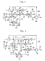
- FIG. 2 is a flow chart showing a mode of the process II.
- the same numerals as used in Fig. 1 denote the same members as a rule.
- the waste water discharged from a waste water tank 1 is heated by a first heat exchanger 13 and a second heat exchanger 65.
- the waste water thus heated is passed through a line 67 to a heater 25.
- the water is admitted to a first reactor 69 and subjected to liquid oxidation without a catalyst in the reactor 69.
- the treated water is introduced into a second reactor 71 and submitted to liquid phase oxidation in the presence of a catalyst of honeycomb construction in the second reactor 71.
- the water is charged into a third reactor 73 and further subjected to liquid phase oxidation in the presence of a granular catalyst.
- the treated water flowing out of the third reactor 73 is led through a line 75 to a gas-liquid separator 53 and separated into a gas running via a line 77 and a liquid running via a line 79.
- the gas flowing through the line 77 is conducted to the heat exchanger 13 to apply thermal energy to the waste water and is drawn off from a line 81.
- the liquid running in the line 79 is sent to the second heat exchanger 65 to heat further the waste water, passed by way of a line 83 to a cooler 49, cooled therein, led through a line 85 under pressure to a reverse osmosis device 59 and separated into clarified water running via a line 61 and concentrated liquid running via a line 63.
- the treated water flowing through the line 45 in Fig. 1 may be optionally sent to an equivalent of the gas-liquid separator shown in Fig. 2 and subsequently processed in the same manner as in the mode in Fig. 2.
- the treated water flowing via the line 75 in Fig. 2 may be optionally admitted to an equivalent of the heat exchanger 13 shown in Fig. 1 and subsequently processed in the same way as in the mode in Fig 1.
- Fig. 3 is a flow chart showing a mode of the process III.
- the process III differs from the process I (Fig. 1) in that the process III includes a reactor 22 for liquid phase oxidation containing a honeycomb structure at a location intermediate between a reactor 21 for liquid phase oxidation without a catalyst and a reactor 34 for liquid phase oxidation in the presence of a catalyst of honeycomb construction.
- Fig. 4 is a flow chart showing a mode of the process IV.
- the process IV differs from the process II (Fig. 2) in that the process IV includes a reactor 70 for liquid phase oxidation containing a honeycomb structure at a location intermediate between a reactor 69 for liquid phase oxidation without a catalyst and a reactor 71 for liquid phase oxidation in the presence of a catalyst of honeycomb construction.
- FIG. 5 is a flow chart showing a mode of the process V.
- waste water is processed in a liquid phase oxidation reactor 22 containing a honeycomb structure and thereafter processed again in a liquid phase oxidation reactor 39 packed with a catalyst of honeycomb construction.
- the process V can be carried out substantially in the same manner as the process I (Fig. 1) in respect of other procedures.
- FIG. 6 is a flow chart showing a mode of the process VI.
- waste water is processed in a liquid phase oxidation reactor 69 containing a honeycomb structure, a liquid phase oxidation reactor 71 packed with a catalyst of honeycomb construction and a liquid phase oxidation reactor 73 packed with a granular catalyst in sequence.
- the process VI is carried out substantially in the same manner as the process II (Fig. 2) in respect of other procedures.
- FIG. 7 is a flow chart showing a mode of the process VII.
- waste water is processed in a liquid phase oxidation reactor 22 containing a catalyst of honeycomb construction and a liquid phase oxidation reactor 73 containing a granular catalyst in sequence.
- the process VII is carried out substantially in the same manner as the process I (Fig. 1) in respect of other procedures.
- Raw human waste is subjected to liquid phase oxidation by the process I according to the mode shown in Fig. 1.
- Table 1 shows the components and properties of the raw human waste used.
- the human waste was passed through a swing disk screen (mesh size: 3 mm) to remove the large-size plastics pieces and paper sheets from the waste.
- Table 2 below shows the components and properties of the waste thus treated.
- the waste treated in the step I-(i) was supplied to the second reactor 39 containing a catalyst supported by a titania carrier of honeycomb construction with square cell apertures (3.5 mm in length of one side) having a cell pitch of 4.5 mm and an aperture ratio of 59.3% and composed of 2% by weight of ruthenium based on the weight of the carrier.
- the reactor 39 had the same empty column volume as the first reactor 21.
- To the reactor 39 was fed a 20% aqueous solution of sodium hydroxide. Then the waste was subjected to liquid phase oxidation.
- the reaction temperature and pressure were the same as those in the step I-(i).
- Table 3 below shows the components and properties of the waste thus treated.
- the treated water obtained in the step I-(ii) was cooled at the heat exchanger 13 and at the cooler 49, and fed to the gas-liquid separator 53.
- the liquid from the separator was introduced into the reverse osmosis device 59 under a pressure adjusted to 65 kg/cm 2 .
- 85 parts by weight of clarified water and 15 parts by weight of concentrated liquid per 100 parts by weight of the liquid supplied were obtained in the reverse osmosis device 59.
- the concentrated liquid was returned by way of the line 63 to the waste water tank 1.
- the gas run off from the gas-liquid separator 53 was found to contain less than 0.01 ppm of NH 3 and less than 0.01 ppm of SO x , but no amount of NO x was detected.
- the water containing suspended solids in a high concentration was treated for 5,000 hours but involved no precipitation nor deposition of solids on the catalyst or no reduction in decomposition efficiency of components. Thus subsequent treatment proceeded without trouble.
- Raw human waste was subjected to liquid phase oxidation by the process II according to the mode shown in Fig. 2.
- the raw human waste used had substantially the same components and properties as those of the waste used in Example 1.
- the combined amount of catalysts used in the steps II-(ii) and II-(iii) was the same as the amount of catalyst in the step I-(ii) of Example 1.
- the catalyst composed of 2% by weight of ruthenium supported by a zirconium honeycomb carrier and the catalyst composed of 2% by weight of ruthenium supported by a zirconium granular carrier (5 mm in diameter) were used in the steps II-(ii) and II-(iii) in a ratio of 1 : 1.
- the other conditions in the steps II-(ii) and II-(iii) were the same as those in the step I-(i) of Example 1.
- a 20% aqueous solution of sodium hydroxide was added at the inlet of the step II-(ii) to adjust the pH of the water to 7.6 at the outlet of the step II-(iii).
- Table 5 below shows the quality of water at each outlet of the steps.
- Example 2 The same raw human waste as used in Example 1 was subjected to liquid phase oxidation by the process II according to the mode shown in Fig. 2.
- the reactions in the steps II-(i), II-(ii) and II-(iii) were carried out all at a temperature of 250°C and pressure of 70 kg/cm 2.
- the liquid space velocity was 1.0 1/hr (based on an empty column) in the step II-(i) and 0.67 1/hr (based on an empty column) in the steps II-(ii) and II-(iii) as combined.
- the catalysts were used in the steps II-(ii) and II-(iii) in a ratio of 1 : 1.
- Table 6 below shows the catalysts used in the steps II-(ii) and II-(iii).
- Example 2 The same raw human waste as used in Example 1 was subjected to liquid phase oxidation by the process I I according to the mode shown in Fig. 2.
- the reactions of the steps II-(i), II-(ii) and II-(iii) were carried out all at a temperature of 280° C and pressure of 90 kg/cm 2.
- the liquid space velocity was 2.0 1/hr (based on an empty column) in the steps I I-(i) and II-(iii) and 1.01 1/hr (based on an empty column) in the step II-(ii).
- the mass velocity was 2.8 t/m 2 hr in the step II-(i).
- the amount of honeycomb catalyst (supported on a zirconia carrier of the same type as used in Example 1) used in the step II-(ii) was twice the amount of granular catalyst (supported on a zirconia carrier of the same type as used in Example 2) in the step II-(iii).
- Air was fed to the inlet in the step II-(i) in an amount corresponding to 0.7 time the theoretical oxygen amount and to the inlet in the step II-(ii) in an amount corresponding to 0.5 time the theoretical oxygen amount.
- a 20% aqueous solution of sodium hydroxide was continuously supplied to the inlets in the steps II-(ii) and II-(iii) to adjust the pH of the water to 7.6 at the outlet of the step II-(iii).
- Tables 7 and 8 below shows the quality of water treated in the steps and the catalysts used in the steps II-(ii) and II-(iii).
- Raw human waste was subjected to liquid phase oxidation in the same manner as in Examples 9 to 12 with the exception of using the catalysts listed below in Tables 9 and 10 in the steps II-(i) and II-(ii).
- Tables 9 and 10 also show the quality of water treated in the steps.
- Sludge sewage in the form of concentrated liquid having the components and properties shown below in Table 11 was subjected to liquid phase oxidation by the process II according to the mode illustrated in Fig. 2.
- the treatment conditions were the same as those in Example 2 except that air was fed in an amount corresponding to 1.2 times the theoretical oxygen amount.
- Table 12 below shows the quality of water treated in the steps.
- the suspended solids in the water being run off from the outlet of the step II-(iii) were analyzed and found to contain 98% nonflammable components. Accordingly the water being treated was fed to a high pressure sedimentation tank (unillustrated) disposed on an intermediate location on the line 85 in Fig. 2 where the suspended solids were separated. After separation, the water was admitted to the reverse osmosis device 59.
- the mixture was fed to a lower portion of the first reaction zone 21 at a space velocity of 2.0 1/hr (based on an empty column) and a mass velocity of 2.39 t/m 2 hr. Air was introduced into the lower portion of the first reaction zone 21 at a space velocity of 89.8 1/hr (based on an empty column, under standard conditions).
- the waste was subjected in this state to liquid phase oxidation without a catalyst at a temperature of 280°C and pressure of 90 kg/cm 2 ⁇ G.
- Table 13 below shows the components and properties of the waste treated in this step.
- the waste treated in the step III-(i) was supplied to the second reaction zone 22 containing a titania honeycomb structure with square cell apertures (3.5 mm in length of one side) having a cell pitch of 4.5 mm and an aperture ratio of 59.3% such that the empty column volume was equivalent to that in the step III-(i).
- the waste was subjected to liquid phase oxidation.
- the reaction temperature and pressure were the same as those in the step III-(i).
- Table 14 below shows the components and properties of the waste thus treated.
- the waste treated in the step III-(ii) was fed to the third reaction zone 39 containing a catalyst supported by the same titania honeycomb structure as used in the step III-(ii) and composed of 2% by weight of palladium based on the weight of the honeycomb structure such that the empty column volume was equivalent to that in the steps III-(i) and III-(ii).
- the waste treated in the step III-(ii) was further subjected in the reaction zone 39 to liquid phase oxidation at a temperature of 280°C and pressure of 90 kg/ ⁇ cm 3 G.
- Table 15 below shows the quality of water resulting from this step.
- the water obtained was so decolorized and deodorized as to resemble tap water in appearance.
- the water obtained in the step III-(iii) was cooled at the heat exchanger 13 and at the cooler 49, and fed to the gas-liquid separator 53.
- the liquid from the separator was introduced into the reverse osmosis device 59 under a pressure adjusted to 65 kg/cm 2 .
- 85 parts by weight of clarified water and 15 parts by weight of concentrated liquid per 100 parts by weight of the liquid supplied were obtained in the reverse osmosis device 59.
- the concentrated liquid was returned by way of the line 63 to the waste water tank 1.
- the gas run off from the gas-liquid separator 53 was found to contain less than 0.01 ppm of NH 3 and less than 0.01 ppm of SO x , but no amount of NO x was detected.
- the waste water containing suspended solids in a high concentration was treated for 5,000 hours but involved no precipitation nor deposition of solids on the catalyst or no reduction in decomposition efficiency of components. Thus subsequent treatment proceeded without trouble.
- Raw human waste was subjected to liquid phase oxidation by the process IV according to the mode shown in Fig. 4.
- the raw human waste used had the same components and properties as those of the waste used in Example 1.
- the amounts of carriers or catalysts used in the steps IV-(ii), IV-(iii) and IV-(iv) were such that the empty column volume was equivalent to that in the step III-(ii) of Example 24.
- the steps IV-(iii) and IV-(iv) each employed a catalyst composed of 2% by weight of ruthenium supported by a titania honeycomb carrier having the same characteristics as the honeycomb structure used in Example 24 or zirconia granular carrier 5 mm in diameter.
- a 20% aqueous solution of sodium hydroxide was supplied to the inlets of the steps IV - (ii) and IV-(iii) to adjust the pH of the water to 7.5 at the outlet of the step IV-(iv).
- Table 17 below shows the quality of water at each outlet of the steps.
- the reactions in the steps IV-(i), IV-(ii), IV-(iii) and and IV-(iv) were carried out all at a temperature of 250°C and pressure of 70 kg/cm 2.
- the liquid space velocity was 1.0 1/hr (based on an empty column) in the steps IV-(i) and IV-(ii), and 0.67.1/hr (based on an empty column) in the steps IV-(iii) and IV-(iv) as combined.
- the catalysts were used in the steps IV-(iii) and IV-(iv) in a ratio of 1 : 1.
- the step IV-(ii) employed a zirconia honeycomb structure having the same characteristics as that used in Example 24 such that the empty colum volume was equivalent to that in the step IV-(i).
- the catalysts used in the steps IV-(iii) and IV-(iv) are shown below in Table 18.
- the step IV-(iii) employed a catalyst supported by a honeycomb structure of the same type as used in Example 24 and the step IV-(iv) used a catalyst supported by a spherical carrier of zirconia 5 mm in diameter and composed of 2% by weight of palladium or ruthenium based on the weight of the carrier.
- Raw human waste was subjected to liquid phase oxidation in the same manner as in Example 27 except that the catalysts listed below in Table 19 were used in the step IV-(iv).
- Table 19 also shows the quality of water treated in the steps.
- Sludge sewage in the form of concentrated liquid having the components and properties shown below in Table 20 was subjected to liquid phase oxidation by the process, IV according to the mode illustrated in Fig. 4.
- the treatment conditions were the same as those in Example 25 except that air was fed in an amount corresponding to 1.2 times the theoretical oxygen amount.
- Table 21 below shows the quality of water treated in the steps.
- the suspended solids in the water being run off from the outlet of the step IV-(iii) were separated and the water was found to show the same appearance as that of tap water and to have been completely deodorized.
- the suspended solids at the outlet of the step IV-(iv) were analyzed and found to contain 98% nonflammable components.
- Raw human waste was subjected to liquid phase oxidation in the same manner as in Example 25 with the exception that the catalysts shown below in Tables 22 and 23 were used in the steps IV-(iii) and IV-(iv).
- Tables 22 and 23 also indicate the quality of water treated in each step.
- Raw human waste is subjected to liquid phase oxidation by the process V according to the mode shown in F ig. 5.
- the components and properties of the raw human waste used were substantially the same as those used in Example 1.
- the mixture was fed to a lower portion of the first reaction zone 21 at a space velocity of 1.0 1/hr (based on an empty column) and a mass velocity of 2.39 t/m 2 hr. Air was introduced into the lower portion of the first reaction zone 21 at a space velocity of 89.8 1/hr (based on an empty column, under standard conditions).
- the reaction zone 21 was provided with a honeycomb structure made of titania with square cell apertures (3.5 mm in length of one side) having a cell pitch of 4.5 mm and an aperture ratio of 59.3% so that the liquid space velocity therein was 1.0 1/hr.
- the waste was subjected to liquid phase oxidation in this state at a temperature of 280°C and pressure of 90 kg/cm 2 ' G.
- Table 24 below shows the components and properties of the waste thus treated.
- the waste treated in the step V-(i) was supplied to the second reaction zone 39 containing a catalyst supported by the same titania carrier of honeycomb construction as used in the step V-(i) and composed of 2% by weight of ruthenium based on the weight of the carrier so that the empty column volume was equivalent to that in the step V-(i).
- a catalyst supported by the same titania carrier of honeycomb construction as used in the step V-(i) and composed of 2% by weight of ruthenium based on the weight of the carrier so that the empty column volume was equivalent to that in the step V-(i).
- To the reaction zone 39 was fed a 20% aqueous solution of sodium hydroxide. Then the waste was subjected to liquid phase oxidation.
- the reaction temperature and pressure were the same as those in the step V-(i).
- Table 25 below shows the components and properties of the waste thus treated at this step.
- the water treated in this step had the same appearance as tap water and was completely deodorized.
- the waste treated in the step V-(ii) was cooled at the heat exchanger 13 and at the cooler 49, and fed to the gas-liquid separator 53.
- the liquid from the separator was introduced into the reverse osmosis device 59 under a pressure adjusted'to 65 kg/cm 2 .
- 85 parts by weight of clarified water and 15 parts by weight of concentrated liquid per 100 parts by weight of the liquid supplied were obtained in the reverse osmosis device 59.
- the concentrated liquid was returned by way of the line 63 to the waste water tank 1.
- the gas run off from the gas-liquid separator 53 was found to contain less than 0.01 ppm of NH 3 and less than 0.01 ppm of SO x , but no amount of NO X was detected.
- the raw human waste containing suspended solids in a high concentration was treated for 5,000 hours but involved no precipitation nor deposition of solids on the catalyst or no reduction in decomposition efficiency of components. Thus subsequent treatment proceeded without trouble.
- Raw human waste was subjected to liquid phase oxidation by the process VI according to the mode shown in Fig. 6.
- the raw human waste used had the same components and properties as those of the waste used in Example 1.
- the combined amount of catalysts used in the steps VI-(ii) and VI-(iii) was the same as the amount of catalyst in the step V-(ii) of Example 47.
- the catalyst composed of 2% by weight of palladium supported by a honeycomb carrier was used in the step VI-(ii) and a catalyst composed of 2% by weight of ruthenium supported by a titania granular carrier 5 mm in diameter in the step VI-(iii).
- the reaction temperature was 250°C and the reaction pressure was 70 kg/cm 3 ⁇ G in the steps VI-(ii) and VI-(iii).
- a 20% aqueous solution of sodium hydroxide was supplied to the inlets of the steps VI-(ii) and VI-(iii) to adjust the pH of the water to 7.5 at the outlet of the step VI-(iii).
- Table 27 below shows the quality of water at each outlet of the steps.
- Example 2 The same raw human waste as treated in Example 1 was subjected to liquid phase oxidation by the process VI according to the mode shown in Fig. 6.
- Table 28 also shows the quality of water treated in the steps VI-(ii) and VI-(iii).
- Example 2 The same raw human waste as used in Example 1 was subjected to liquid phase oxidation by the process VI according to the mode shown in Fig. 6.
- Sludge sewage in the form of concentrated liquid having the components and properties shown below in Table 31 was subjected to liquid phase oxidation by the process V according to the mode illustrated in Fig. 5.
- the treatment conditions were the same as those in Example 47 except that air was fed in an amount corresponding to 1.2 times the theoretical oxygen amount and that the liquid space velocity was 0.67 1/hr in the step V-(ii).
- Table 32 below shows the quality of water treated in the steps.
- the suspended solids in the water being run off from the outlet of the step V-(ii) were analyzed and found to contain 98% nonflammable components. Accordingly the water being run off was fed to a high pressure sedimentation tank (unillustrated) disposed on an intermediate location on the line 57 in Fig. 5 where the suspended solids were separated. After separation, the water was admitted to the reverse osmosis device 59.
- Raw human waste is subjected to liquid phase oxidation by the process VII according to the mode shown in Fig. 7.
- the components and properties of the human waste used were the same as those used in Example 1.
- the mixture was fed to a lower portion of the first reaction zone 21 at a space velocity of 1.0 1/hr (based on an empty column) and a mass velocity of 2.39 t/m 2 hr. Air was introduced into the lower portion of the first reaction zone 21 at a space velocity of 89.8 1/hr (based on an empty column, under standard conditions).
- the first reaction zone 21 was charged with a catalyst supported by a titania honeycomb structure with square cell apertures (3.5 mm in length of one side) having a cell pitch of 4.5 mm and an aperture ratio of 59.3% and composed of 2% by weight of ruthenium based on the weight of the honeycomb structure.
- the waste was subjected in this state to liquid phase oxidation at a temperature of 250°C and pressure of 70 kg/cm 2.
- the waste treated in the step VII-(i) was supplied to the second reaction zone 39 packed with a granular catalyst supported by a titania carrier 6 mm in particle size and composed of 2% by weight of ruthenium based on the weight of the carrier such that the empty column volumn was equivalent to that in the step VII-(i).
- a 20% aqueous solution of sodium hydroxide After feed of a 20% aqueous solution of sodium hydroxide, the waste was subjected to liquid phase oxidation.
- the reaction temperature and pressure were the same as those in the step VII-(i).
- Table 33 below shows the components and properties of the waste thus treated.
- the water obtained in the step VII-(ii) had the same appearance as that of tap water and was completely deodorized.
- the waste treated in the step VII-(ii) was cooled at the heat exchanger 13 and at the cooler 49, and fed to the gas-liquid separator 53.
- the liquid from the separator was introduced into the reverse osmosis device 59 under a pressure adjusted to 65 kg/cm 2 .
- 85 parts by weight of clarified water and 15 parts by weight of concentrated liquid per 100 parts by weight of the liquid supplied were obtained in the reverse osmosis device 59.
- the concentrated liquid was returned by way of the line 63 to the waste water tank 1.
- the gas run off from the gas-liquid separator 53 was found to contain less than 0.01 ppm of NH 3 and less than 0.01 ppm of SO x , but no amount of NO X was detected.
- the water containing suspended solids in a high concentration was treated for 5,000 hours but involved no precipitation nor deposition of solids on the catalyst or no reduction in decomposition efficiency of components. Thus subsequent treatment proceeded without trouble.
- Raw human waste was subjected to liquid phase oxidation in the same manner as in Example 70 except that the catalysts listed below in Tables 35 and 36 were used in the steps VII-(i) and VII-(ii).
- Tables 35 and 36 also show the quality of water treated in the steps.
- Sludge sewage in the form of concentrated liquid having the components and properties shown below in Table 37 was subjected to liquid phase oxidation by the process VII.
- the treatment conditions were the same as those in Example 70 except that air was fed in an amount corresponding to 1.2 times the theoretical oxygen amount.
- Table 38 below shows the quality of water treated in the steps.
- the suspended solids in the water being run off from the outlet of the step VII-(ii) were analyzed and found to show the same appearance as tap water and to have been completely deodorized.
Applications Claiming Priority (8)
| Application Number | Priority Date | Filing Date | Title |
|---|---|---|---|
| JP272082/85 | 1985-12-03 | ||
| JP27208285A JPS62132589A (ja) | 1985-12-03 | 1985-12-03 | 廃水の湿式酸化処理方法 |
| JP27419485A JPS62132592A (ja) | 1985-12-04 | 1985-12-04 | 廃水の湿式酸化処理方法 |
| JP27419285A JPS62132590A (ja) | 1985-12-04 | 1985-12-04 | 廃水の湿式酸化処理方法 |
| JP274192/85 | 1985-12-04 | ||
| JP274193/85 | 1985-12-04 | ||
| JP27419385A JPS62132591A (ja) | 1985-12-04 | 1985-12-04 | 廃水の湿式酸化処理方法 |
| JP274194/85 | 1985-12-04 |
Publications (3)
| Publication Number | Publication Date |
|---|---|
| EP0224905A2 true EP0224905A2 (de) | 1987-06-10 |
| EP0224905A3 EP0224905A3 (en) | 1988-08-03 |
| EP0224905B1 EP0224905B1 (de) | 1993-09-29 |
Family
ID=27478942
Family Applications (1)
| Application Number | Title | Priority Date | Filing Date |
|---|---|---|---|
| EP86116707A Expired - Lifetime EP0224905B1 (de) | 1985-12-03 | 1986-12-02 | Verfahren für die Abwasserbehandlung mit Nassoxidation |
Country Status (5)
| Country | Link |
|---|---|
| US (1) | US4699720A (de) |
| EP (1) | EP0224905B1 (de) |
| CN (1) | CN1017522B (de) |
| CA (1) | CA1295754C (de) |
| DE (1) | DE3689105T2 (de) |
Cited By (5)
| Publication number | Priority date | Publication date | Assignee | Title |
|---|---|---|---|---|
| EP0413356A1 (de) * | 1989-08-18 | 1991-02-20 | Osaka Gas Co., Ltd. | Verfahren zur Abwasserbehandlung |
| FR2717461A1 (fr) * | 1994-03-21 | 1995-09-22 | Omnium Traitement Valorisa | Procédé intégré de traitement d'effluents industriels et/ou urbains contenant des composés azotés et une proportion importante de matière organique en suspension. |
| FR2717460A1 (fr) * | 1994-03-21 | 1995-09-22 | Omnium Traitement Valorisa | Procédé et installation de traitement d'effluents chargés en matière organique, notamment par oxydation en milieu humide, avec recyclage interne des résidus solides. |
| EP0690025A3 (de) * | 1994-06-27 | 1998-07-01 | Fuji Photo Film Co., Ltd. | Verfahren zur Behandlung einer photographischen Schmutzlösung |
| CN106362751A (zh) * | 2016-08-29 | 2017-02-01 | 江苏海普功能材料有限公司 | 一种非均相催化剂及其制备、应用方法 |
Families Citing this family (34)
| Publication number | Priority date | Publication date | Assignee | Title |
|---|---|---|---|---|
| US4751005A (en) * | 1986-08-22 | 1988-06-14 | Nippon Shokubai Kagaku Kogyo Co., Ltd. | Method for treatment of waste water |
| US5205906A (en) * | 1988-08-08 | 1993-04-27 | Chemical Waste Management, Inc. | Process for the catalytic treatment of wastewater |
| US5194161A (en) * | 1989-09-25 | 1993-03-16 | Board Of Regents, The University Of Texas System | Materials and methods for enhanced photocatalyzation of organic compounds with palladium |
| US5234584A (en) * | 1991-02-04 | 1993-08-10 | United Technologies Corporation | Catalytic oxidation of aqueous organic contaminants |
| US5620610A (en) * | 1991-05-14 | 1997-04-15 | Nippon Shokubai Co., Ltd. | Catalyst for treating wastewater, process for producing it, and process for treating wastewater with the catalyst |
| US5183577A (en) * | 1992-01-06 | 1993-02-02 | Zimpro Passavant Environmental Systems, Inc. | Process for treatment of wastewater containing inorganic ammonium salts |
| US5160636A (en) * | 1992-01-17 | 1992-11-03 | Chemical Waste Management, Inc. | Process for the treatment of mixed wastes |
| US5266174A (en) * | 1992-05-12 | 1993-11-30 | Martin Marietta Energy Systems, Inc. | Process for reducing aqueous nitrate to ammonia |
| CN1045076C (zh) * | 1992-09-22 | 1999-09-15 | 中国科学院大连化学物理研究所 | 含高浓度有机物及氨工业污水湿式氧化净化催化剂及制备方法 |
| US5338463A (en) * | 1993-05-12 | 1994-08-16 | Mobil Oil Corporation | Wastewater treatment by catalytic oxidation |
| US5360552A (en) * | 1993-05-12 | 1994-11-01 | Mobil Oil Corporation | Removal of cyanide, sulfides and thiosulfate from ammonia-containing wastewater by catalytic oxidation |
| US5470486A (en) * | 1994-06-20 | 1995-11-28 | Uop | Conversion of water-soluble inorganic sulfide compounds in an aqueous stream |
| FR2726261B1 (fr) * | 1994-10-27 | 1997-01-17 | Omnium Traitement Valorisa | Procede et installation de traitement d'effluents par oxydation en presence d'un catalyseur heterogene |
| FR2726262B1 (fr) * | 1994-10-27 | 1998-06-26 | Omnium Traitement Valorisa | Procede et installation de traitement d'effluents par oxydation en presence d'un catalyseur heterogene |
| US5785868A (en) * | 1995-09-11 | 1998-07-28 | Board Of Regents, Univ. Of Texas System | Method for selective separation of products at hydrothermal conditions |
| US6419837B1 (en) | 1998-08-06 | 2002-07-16 | Umpqua Research Company | Process for destroying contaminants in contaminant-containing aqueous streams and catalysts used therefor |
| US6238574B1 (en) * | 1998-10-30 | 2001-05-29 | The Standard Oil Company | Oxidation and ammoxidation of acrylonitrile process waste water organics |
| KR100403412B1 (ko) | 1999-01-07 | 2003-10-30 | 니폰 쇼쿠바이 컴파니 리미티드 | 배수 처리법 |
| KR100451646B1 (ko) * | 2000-01-05 | 2004-10-08 | 니폰 쇼쿠바이 컴파니 리미티드 | 배수처리용 촉매, 그의 제조방법 및 배수의 처리방법 |
| CN1323036C (zh) * | 2002-03-11 | 2007-06-27 | 株式会社日本触媒 | 废水处理方法 |
| US6716360B2 (en) * | 2002-04-16 | 2004-04-06 | Eau-Viron Incorporated | Method and apparatus for treating waste streams |
| TW200425940A (en) * | 2003-05-16 | 2004-12-01 | Chung Shan Inst Of Science | An air cleaning florescent lamp coated with photocatalysis materials |
| US7371323B1 (en) | 2004-08-11 | 2008-05-13 | Spielman Rick B | System and method for reducing wastewater contaminants |
| US7578939B2 (en) * | 2004-12-09 | 2009-08-25 | Board Of Trustees Of Michigan State University | Ceramic membrane water filtration |
| US7537702B2 (en) * | 2005-04-12 | 2009-05-26 | Honeywell International Inc. | Water purification system and modes of operation |
| CN100402146C (zh) * | 2006-09-13 | 2008-07-16 | 北京交通大学 | 活性炭载氧化铁催化剂及其制备方法 |
| JP2010516446A (ja) * | 2007-01-22 | 2010-05-20 | シーメンス ウォーター テクノロジース コーポレイション | 再循環触媒を使用する湿式空気酸化方法 |
| CN101798136B (zh) * | 2010-04-26 | 2012-05-30 | 哈尔滨工业大学 | 去除水中有机污染物的方法 |
| CN102284294A (zh) * | 2010-06-18 | 2011-12-21 | 上海牛翼新能源科技有限公司 | 低温吸收和催化分解去除氨 |
| CN102372357A (zh) * | 2010-08-20 | 2012-03-14 | 中国科学院成都有机化学有限公司 | 一种催化湿式氧化预处理焦化废水的方法 |
| CN105692866B (zh) * | 2014-11-27 | 2018-07-13 | 中国海洋石油集团有限公司 | 一种处理高酸重质原油加工废水的催化剂的装填方法 |
| CN105080933A (zh) * | 2015-08-07 | 2015-11-25 | 浙江奇彩环境科技有限公司 | 一种有机固废的处理方法 |
| CN105693011A (zh) * | 2016-01-22 | 2016-06-22 | 济钢集团国际工程技术有限公司 | 一种焦化酚氰废水深度处理装置 |
| CN107352679B (zh) * | 2017-07-11 | 2022-01-07 | 河南中鸿集团煤化有限公司 | 一种脱硫液提盐工艺及其装置 |
Citations (13)
| Publication number | Priority date | Publication date | Assignee | Title |
|---|---|---|---|---|
| JPS53106711A (en) | 1977-02-28 | 1978-09-18 | Sakai Chemical Industry Co | Continuous extrusion molding of ceramic honeycomb structures and dies for continuous extrusion |
| JPS53133592A (en) | 1977-04-26 | 1978-11-21 | Sakai Chem Ind Co Ltd | Dies, production using the same, and catalyst or carrier |
| US4141828A (en) | 1976-08-10 | 1979-02-27 | Osaka Gas Company, Limited | Process for treating waste water |
| JPS5457505A (en) | 1977-10-15 | 1979-05-09 | Sakai Chemical Industry Co | Honeycomb structure |
| JPS5472788A (en) | 1977-11-22 | 1979-06-11 | Sakai Chem Ind Co Ltd | Honeycomb structure and catalytic reactor |
| JPS54132469A (en) | 1978-04-05 | 1979-10-15 | Sakai Chem Ind Co Ltd | Packing method for catalyst |
| JPS55140546A (en) | 1979-03-09 | 1980-11-04 | Sakai Chemical Industry Co | Honeycomb structure |
| JPS5642992B2 (de) | 1977-09-12 | 1981-10-08 | ||
| US4294706A (en) | 1979-05-16 | 1981-10-13 | Osaka Gas Company, Limited | Process for treating waste water |
| JPS5733320B2 (de) | 1979-05-30 | 1982-07-16 | ||
| JPS5742391B2 (de) | 1978-12-15 | 1982-09-08 | ||
| JPS5827999B2 (ja) | 1978-12-22 | 1983-06-13 | 大阪瓦斯株式会社 | 廃水の湿式酸化処理方法 |
| JPS5949073B2 (ja) | 1981-10-15 | 1984-11-30 | 大阪瓦斯株式会社 | 廃水の処理方法 |
Family Cites Families (7)
| Publication number | Priority date | Publication date | Assignee | Title |
|---|---|---|---|---|
| US2690425A (en) * | 1950-03-23 | 1954-09-28 | Du Pont | Waste disposal process |
| DE2534892B2 (de) * | 1975-08-05 | 1979-07-05 | Bayer Ag, 5090 Leverkusen | Verfahren zur oxydativen Behandlung sulfid-, sulfit- und thiosulfathaltiger Abwasser |
| US4018568A (en) * | 1976-02-09 | 1977-04-19 | Uop Inc. | Fume absorbing-treating system |
| US4203838A (en) * | 1976-03-13 | 1980-05-20 | Kubota Tekko Kabushiki Kaisha | Process for the treatment of sludge |
| JPS531957A (en) * | 1976-06-25 | 1978-01-10 | Nippon Petrochemicals Co Ltd | Method and apparatus for wet oxidative treating method of waste liquor |
| CA1224891A (en) * | 1984-03-28 | 1987-07-28 | Kenox Corporation | Wet oxidation system |
| US4654149A (en) * | 1985-03-28 | 1987-03-31 | Osaka Gas Company Limited | Process for treating ammonium nitrate-containing waste water |
-
1986
- 1986-12-01 US US06/936,230 patent/US4699720A/en not_active Expired - Lifetime
- 1986-12-02 CA CA000524359A patent/CA1295754C/en not_active Expired - Fee Related
- 1986-12-02 EP EP86116707A patent/EP0224905B1/de not_active Expired - Lifetime
- 1986-12-02 DE DE86116707T patent/DE3689105T2/de not_active Expired - Fee Related
- 1986-12-03 CN CN86108846A patent/CN1017522B/zh not_active Expired
Patent Citations (15)
| Publication number | Priority date | Publication date | Assignee | Title |
|---|---|---|---|---|
| US4141828A (en) | 1976-08-10 | 1979-02-27 | Osaka Gas Company, Limited | Process for treating waste water |
| JPS5919757B2 (ja) | 1976-08-10 | 1984-05-08 | 大阪瓦斯株式会社 | 廃水の処理方法 |
| JPS53106711A (en) | 1977-02-28 | 1978-09-18 | Sakai Chemical Industry Co | Continuous extrusion molding of ceramic honeycomb structures and dies for continuous extrusion |
| JPS53133592A (en) | 1977-04-26 | 1978-11-21 | Sakai Chem Ind Co Ltd | Dies, production using the same, and catalyst or carrier |
| JPS5642992B2 (de) | 1977-09-12 | 1981-10-08 | ||
| JPS5457505A (en) | 1977-10-15 | 1979-05-09 | Sakai Chemical Industry Co | Honeycomb structure |
| JPS5472788A (en) | 1977-11-22 | 1979-06-11 | Sakai Chem Ind Co Ltd | Honeycomb structure and catalytic reactor |
| JPS54132469A (en) | 1978-04-05 | 1979-10-15 | Sakai Chem Ind Co Ltd | Packing method for catalyst |
| JPS5742391B2 (de) | 1978-12-15 | 1982-09-08 | ||
| JPS5827999B2 (ja) | 1978-12-22 | 1983-06-13 | 大阪瓦斯株式会社 | 廃水の湿式酸化処理方法 |
| JPS55140546A (en) | 1979-03-09 | 1980-11-04 | Sakai Chemical Industry Co | Honeycomb structure |
| US4294706A (en) | 1979-05-16 | 1981-10-13 | Osaka Gas Company, Limited | Process for treating waste water |
| JPS5929317B2 (ja) | 1979-05-16 | 1984-07-19 | 大阪瓦斯株式会社 | 廃水処理方法 |
| JPS5733320B2 (de) | 1979-05-30 | 1982-07-16 | ||
| JPS5949073B2 (ja) | 1981-10-15 | 1984-11-30 | 大阪瓦斯株式会社 | 廃水の処理方法 |
Cited By (8)
| Publication number | Priority date | Publication date | Assignee | Title |
|---|---|---|---|---|
| EP0413356A1 (de) * | 1989-08-18 | 1991-02-20 | Osaka Gas Co., Ltd. | Verfahren zur Abwasserbehandlung |
| US5057220A (en) * | 1989-08-18 | 1991-10-15 | Osaka Gas Company Limited | Process for treating waste water |
| FR2717461A1 (fr) * | 1994-03-21 | 1995-09-22 | Omnium Traitement Valorisa | Procédé intégré de traitement d'effluents industriels et/ou urbains contenant des composés azotés et une proportion importante de matière organique en suspension. |
| FR2717460A1 (fr) * | 1994-03-21 | 1995-09-22 | Omnium Traitement Valorisa | Procédé et installation de traitement d'effluents chargés en matière organique, notamment par oxydation en milieu humide, avec recyclage interne des résidus solides. |
| WO1995025698A1 (fr) * | 1994-03-21 | 1995-09-28 | Otv Omnium De Traitements Et De Valorisation | Procede et installation de traitement d'effluents charges en matiere organique, notamment par oxydation en milieu humide, avec recyclage interne des residus solides, et station d'epuration correspondante |
| US5948275A (en) * | 1994-03-21 | 1999-09-07 | Otv Omnium De Traltements Et De Valorisation S.A. | Method and facility for treating effluents loaded with organic material, particularly by wet oxidation and with internal solid residue recycling, and purification facility therefor |
| EP0690025A3 (de) * | 1994-06-27 | 1998-07-01 | Fuji Photo Film Co., Ltd. | Verfahren zur Behandlung einer photographischen Schmutzlösung |
| CN106362751A (zh) * | 2016-08-29 | 2017-02-01 | 江苏海普功能材料有限公司 | 一种非均相催化剂及其制备、应用方法 |
Also Published As
| Publication number | Publication date |
|---|---|
| DE3689105T2 (de) | 1994-02-03 |
| CA1295754C (en) | 1992-02-11 |
| EP0224905A3 (en) | 1988-08-03 |
| US4699720A (en) | 1987-10-13 |
| CN86108846A (zh) | 1987-07-29 |
| DE3689105D1 (de) | 1993-11-04 |
| EP0224905B1 (de) | 1993-09-29 |
| CN1017522B (zh) | 1992-07-22 |
Similar Documents
| Publication | Publication Date | Title |
|---|---|---|
| US4699720A (en) | Process for treating waste water by wet oxidations | |
| EP0413356B1 (de) | Verfahren zur Abwasserbehandlung | |
| US4294706A (en) | Process for treating waste water | |
| US4141828A (en) | Process for treating waste water | |
| US4654149A (en) | Process for treating ammonium nitrate-containing waste water | |
| EP0690025B1 (de) | Verfahren zur Behandlung einer photographischen Schmutzlösung | |
| GB2043045A (en) | Process for treating ammonia- containing waste water | |
| JP2000117273A (ja) | 廃水の処理方法 | |
| JP2000117272A (ja) | 廃水の処理方法 | |
| JPH0454512B2 (de) | ||
| JPH0454515B2 (de) | ||
| JP2627953B2 (ja) | 廃水の処理方法 | |
| JPH0454514B2 (de) | ||
| JPH11300374A (ja) | 排水の処理方法 | |
| JPH0454513B2 (de) | ||
| JPH0231896A (ja) | 廃水の処理装置 | |
| JPH05261394A (ja) | 高濃度有機廃液の処理方法 | |
| JPS6351730B2 (de) | ||
| JPH0326399A (ja) | 高濃度有機廃液の処理方法 | |
| JP2000084575A (ja) | 水溶液中のアンモニアを効率良く酸化する方法 | |
| JPS61222589A (ja) | 硝酸アンモニウム含有廃水の処理方法 | |
| JP2002273458A (ja) | 排水の処理方法 | |
| JPS61222586A (ja) | 硝酸アンモニウム含有廃水の処理方法 | |
| JPH0647100B2 (ja) | 硝酸アンモニウム含有廃水の処理方法 | |
| JPH11253972A (ja) | 選択的酸化方法 |
Legal Events
| Date | Code | Title | Description |
|---|---|---|---|
| PUAI | Public reference made under article 153(3) epc to a published international application that has entered the european phase |
Free format text: ORIGINAL CODE: 0009012 |
|
| AK | Designated contracting states |
Kind code of ref document: A2 Designated state(s): DE FR GB NL |
|
| PUAL | Search report despatched |
Free format text: ORIGINAL CODE: 0009013 |
|
| AK | Designated contracting states |
Kind code of ref document: A3 Designated state(s): DE FR GB NL |
|
| 17P | Request for examination filed |
Effective date: 19881013 |
|
| 17Q | First examination report despatched |
Effective date: 19910314 |
|
| GRAA | (expected) grant |
Free format text: ORIGINAL CODE: 0009210 |
|
| AK | Designated contracting states |
Kind code of ref document: B1 Designated state(s): DE FR GB NL |
|
| REF | Corresponds to: |
Ref document number: 3689105 Country of ref document: DE Date of ref document: 19931104 |
|
| ET | Fr: translation filed | ||
| PLBE | No opposition filed within time limit |
Free format text: ORIGINAL CODE: 0009261 |
|
| STAA | Information on the status of an ep patent application or granted ep patent |
Free format text: STATUS: NO OPPOSITION FILED WITHIN TIME LIMIT |
|
| 26N | No opposition filed | ||
| PGFP | Annual fee paid to national office [announced via postgrant information from national office to epo] |
Ref country code: GB Payment date: 19961125 Year of fee payment: 11 |
|
| PGFP | Annual fee paid to national office [announced via postgrant information from national office to epo] |
Ref country code: FR Payment date: 19961127 Year of fee payment: 11 |
|
| PGFP | Annual fee paid to national office [announced via postgrant information from national office to epo] |
Ref country code: NL Payment date: 19961231 Year of fee payment: 11 |
|
| PG25 | Lapsed in a contracting state [announced via postgrant information from national office to epo] |
Ref country code: GB Free format text: LAPSE BECAUSE OF NON-PAYMENT OF DUE FEES Effective date: 19971202 |
|
| PG25 | Lapsed in a contracting state [announced via postgrant information from national office to epo] |
Ref country code: FR Free format text: THE PATENT HAS BEEN ANNULLED BY A DECISION OF A NATIONAL AUTHORITY Effective date: 19971231 |
|
| PGFP | Annual fee paid to national office [announced via postgrant information from national office to epo] |
Ref country code: DE Payment date: 19980227 Year of fee payment: 12 |
|
| PG25 | Lapsed in a contracting state [announced via postgrant information from national office to epo] |
Ref country code: NL Free format text: LAPSE BECAUSE OF NON-PAYMENT OF DUE FEES Effective date: 19980701 |
|
| GBPC | Gb: european patent ceased through non-payment of renewal fee |
Effective date: 19971202 |
|
| NLV4 | Nl: lapsed or anulled due to non-payment of the annual fee |
Effective date: 19980701 |
|
| REG | Reference to a national code |
Ref country code: FR Ref legal event code: ST |
|
| PG25 | Lapsed in a contracting state [announced via postgrant information from national office to epo] |
Ref country code: DE Free format text: LAPSE BECAUSE OF NON-PAYMENT OF DUE FEES Effective date: 19991001 |