EP0224659B1 - Méthode pour améliorer la qualité de la surface de particules solides et appareil à cet effet - Google Patents
Méthode pour améliorer la qualité de la surface de particules solides et appareil à cet effet Download PDFInfo
- Publication number
- EP0224659B1 EP0224659B1 EP86112228A EP86112228A EP0224659B1 EP 0224659 B1 EP0224659 B1 EP 0224659B1 EP 86112228 A EP86112228 A EP 86112228A EP 86112228 A EP86112228 A EP 86112228A EP 0224659 B1 EP0224659 B1 EP 0224659B1
- Authority
- EP
- European Patent Office
- Prior art keywords
- particles
- powder
- solid particles
- impact
- collision
- Prior art date
- Legal status (The legal status is an assumption and is not a legal conclusion. Google has not performed a legal analysis and makes no representation as to the accuracy of the status listed.)
- Expired - Lifetime
Links
- 239000002245 particle Substances 0.000 title claims description 404
- 239000007787 solid Substances 0.000 title claims description 62
- 238000000034 method Methods 0.000 title claims description 56
- 239000011261 inert gas Substances 0.000 claims description 35
- 239000010419 fine particle Substances 0.000 claims description 21
- 239000007789 gas Substances 0.000 claims description 15
- 239000007788 liquid Substances 0.000 claims description 15
- 238000002844 melting Methods 0.000 claims description 8
- 230000008018 melting Effects 0.000 claims description 8
- 230000002093 peripheral effect Effects 0.000 claims description 7
- 238000001035 drying Methods 0.000 claims description 6
- 239000012530 fluid Substances 0.000 claims description 5
- 239000000110 cooling liquid Substances 0.000 claims description 2
- 238000010438 heat treatment Methods 0.000 claims description 2
- 230000003116 impacting effect Effects 0.000 claims 1
- 230000000153 supplemental effect Effects 0.000 claims 1
- 239000000843 powder Substances 0.000 description 188
- 239000000463 material Substances 0.000 description 55
- GWEVSGVZZGPLCZ-UHFFFAOYSA-N Titan oxide Chemical compound O=[Ti]=O GWEVSGVZZGPLCZ-UHFFFAOYSA-N 0.000 description 29
- 229910052751 metal Inorganic materials 0.000 description 27
- 239000002184 metal Substances 0.000 description 27
- 230000006872 improvement Effects 0.000 description 22
- 239000004408 titanium dioxide Substances 0.000 description 14
- -1 polyethylene Polymers 0.000 description 12
- JHWNWJKBPDFINM-UHFFFAOYSA-N Laurolactam Chemical compound O=C1CCCCCCCCCCCN1 JHWNWJKBPDFINM-UHFFFAOYSA-N 0.000 description 11
- 229920000299 Nylon 12 Polymers 0.000 description 11
- 239000000126 substance Substances 0.000 description 11
- 239000004677 Nylon Substances 0.000 description 10
- 239000002131 composite material Substances 0.000 description 10
- 229920001778 nylon Polymers 0.000 description 10
- 229920002472 Starch Polymers 0.000 description 9
- 239000008107 starch Substances 0.000 description 9
- 235000019698 starch Nutrition 0.000 description 9
- XEEYBQQBJWHFJM-UHFFFAOYSA-N Iron Chemical compound [Fe] XEEYBQQBJWHFJM-UHFFFAOYSA-N 0.000 description 8
- PPBRXRYQALVLMV-UHFFFAOYSA-N Styrene Chemical compound C=CC1=CC=CC=C1 PPBRXRYQALVLMV-UHFFFAOYSA-N 0.000 description 8
- 239000002994 raw material Substances 0.000 description 8
- 239000000725 suspension Substances 0.000 description 8
- RYGMFSIKBFXOCR-UHFFFAOYSA-N Copper Chemical compound [Cu] RYGMFSIKBFXOCR-UHFFFAOYSA-N 0.000 description 7
- BQCADISMDOOEFD-UHFFFAOYSA-N Silver Chemical compound [Ag] BQCADISMDOOEFD-UHFFFAOYSA-N 0.000 description 7
- 239000000835 fiber Substances 0.000 description 7
- 239000003973 paint Substances 0.000 description 7
- 239000002356 single layer Substances 0.000 description 7
- 239000001993 wax Substances 0.000 description 7
- VTYYLEPIZMXCLO-UHFFFAOYSA-L Calcium carbonate Chemical compound [Ca+2].[O-]C([O-])=O VTYYLEPIZMXCLO-UHFFFAOYSA-L 0.000 description 6
- 239000000919 ceramic Substances 0.000 description 6
- 239000010949 copper Substances 0.000 description 6
- 229910052802 copper Inorganic materials 0.000 description 6
- 229920001971 elastomer Polymers 0.000 description 6
- 239000010410 layer Substances 0.000 description 6
- 239000003094 microcapsule Substances 0.000 description 6
- 239000005060 rubber Substances 0.000 description 6
- 238000007669 thermal treatment Methods 0.000 description 6
- 239000001913 cellulose Substances 0.000 description 5
- 229920002678 cellulose Polymers 0.000 description 5
- 238000000576 coating method Methods 0.000 description 5
- 239000011162 core material Substances 0.000 description 5
- 239000002537 cosmetic Substances 0.000 description 5
- 239000003814 drug Substances 0.000 description 5
- 235000013305 food Nutrition 0.000 description 5
- 239000002923 metal particle Substances 0.000 description 5
- 229920003023 plastic Polymers 0.000 description 5
- 239000004033 plastic Substances 0.000 description 5
- 230000008569 process Effects 0.000 description 5
- OKTJSMMVPCPJKN-UHFFFAOYSA-N Carbon Chemical compound [C] OKTJSMMVPCPJKN-UHFFFAOYSA-N 0.000 description 4
- 239000004593 Epoxy Substances 0.000 description 4
- UQSXHKLRYXJYBZ-UHFFFAOYSA-N Iron oxide Chemical compound [Fe]=O UQSXHKLRYXJYBZ-UHFFFAOYSA-N 0.000 description 4
- PXHVJJICTQNCMI-UHFFFAOYSA-N Nickel Chemical compound [Ni] PXHVJJICTQNCMI-UHFFFAOYSA-N 0.000 description 4
- 239000004698 Polyethylene Substances 0.000 description 4
- VYPSYNLAJGMNEJ-UHFFFAOYSA-N Silicium dioxide Chemical compound O=[Si]=O VYPSYNLAJGMNEJ-UHFFFAOYSA-N 0.000 description 4
- ATJFFYVFTNAWJD-UHFFFAOYSA-N Tin Chemical compound [Sn] ATJFFYVFTNAWJD-UHFFFAOYSA-N 0.000 description 4
- HCHKCACWOHOZIP-UHFFFAOYSA-N Zinc Chemical compound [Zn] HCHKCACWOHOZIP-UHFFFAOYSA-N 0.000 description 4
- 230000009102 absorption Effects 0.000 description 4
- 238000010521 absorption reaction Methods 0.000 description 4
- 238000013019 agitation Methods 0.000 description 4
- 238000010009 beating Methods 0.000 description 4
- 229910052742 iron Inorganic materials 0.000 description 4
- 239000000203 mixture Substances 0.000 description 4
- 239000005445 natural material Substances 0.000 description 4
- 229920003229 poly(methyl methacrylate) Polymers 0.000 description 4
- 229920000573 polyethylene Polymers 0.000 description 4
- 239000004926 polymethyl methacrylate Substances 0.000 description 4
- 239000011135 tin Substances 0.000 description 4
- 229910052718 tin Inorganic materials 0.000 description 4
- XLYOFNOQVPJJNP-UHFFFAOYSA-N water Substances O XLYOFNOQVPJJNP-UHFFFAOYSA-N 0.000 description 4
- 108010010803 Gelatin Proteins 0.000 description 3
- 239000004793 Polystyrene Substances 0.000 description 3
- PNEYBMLMFCGWSK-UHFFFAOYSA-N aluminium oxide Inorganic materials [O-2].[O-2].[O-2].[Al+3].[Al+3] PNEYBMLMFCGWSK-UHFFFAOYSA-N 0.000 description 3
- 229910000019 calcium carbonate Inorganic materials 0.000 description 3
- 230000006835 compression Effects 0.000 description 3
- 238000007906 compression Methods 0.000 description 3
- 239000007771 core particle Substances 0.000 description 3
- 230000005611 electricity Effects 0.000 description 3
- 229920000159 gelatin Polymers 0.000 description 3
- 239000008273 gelatin Substances 0.000 description 3
- 235000019322 gelatine Nutrition 0.000 description 3
- 235000011852 gelatine desserts Nutrition 0.000 description 3
- 239000011133 lead Substances 0.000 description 3
- 238000004519 manufacturing process Methods 0.000 description 3
- 239000005416 organic matter Substances 0.000 description 3
- 229920002223 polystyrene Polymers 0.000 description 3
- 239000004332 silver Substances 0.000 description 3
- 229910052709 silver Inorganic materials 0.000 description 3
- 239000012798 spherical particle Substances 0.000 description 3
- 230000003068 static effect Effects 0.000 description 3
- 229910052725 zinc Inorganic materials 0.000 description 3
- 239000011701 zinc Substances 0.000 description 3
- 229920002292 Nylon 6 Polymers 0.000 description 2
- 239000004743 Polypropylene Substances 0.000 description 2
- NINIDFKCEFEMDL-UHFFFAOYSA-N Sulfur Chemical compound [S] NINIDFKCEFEMDL-UHFFFAOYSA-N 0.000 description 2
- 239000006230 acetylene black Substances 0.000 description 2
- 238000005054 agglomeration Methods 0.000 description 2
- 230000002776 aggregation Effects 0.000 description 2
- TZCXTZWJZNENPQ-UHFFFAOYSA-L barium sulfate Chemical compound [Ba+2].[O-]S([O-])(=O)=O TZCXTZWJZNENPQ-UHFFFAOYSA-L 0.000 description 2
- 239000011230 binding agent Substances 0.000 description 2
- 230000008859 change Effects 0.000 description 2
- 239000003795 chemical substances by application Substances 0.000 description 2
- 239000000084 colloidal system Substances 0.000 description 2
- 239000006185 dispersion Substances 0.000 description 2
- 230000000694 effects Effects 0.000 description 2
- 239000000839 emulsion Substances 0.000 description 2
- 238000004880 explosion Methods 0.000 description 2
- 238000011049 filling Methods 0.000 description 2
- 239000000499 gel Substances 0.000 description 2
- 230000007246 mechanism Effects 0.000 description 2
- 150000002736 metal compounds Chemical class 0.000 description 2
- 238000002156 mixing Methods 0.000 description 2
- 239000004570 mortar (masonry) Substances 0.000 description 2
- 229910052759 nickel Inorganic materials 0.000 description 2
- 230000003647 oxidation Effects 0.000 description 2
- 238000007254 oxidation reaction Methods 0.000 description 2
- 239000000049 pigment Substances 0.000 description 2
- 229920001155 polypropylene Polymers 0.000 description 2
- 230000002265 prevention Effects 0.000 description 2
- 239000003507 refrigerant Substances 0.000 description 2
- 230000004044 response Effects 0.000 description 2
- 238000005096 rolling process Methods 0.000 description 2
- 239000000377 silicon dioxide Substances 0.000 description 2
- 239000008279 sol Substances 0.000 description 2
- 229910052717 sulfur Inorganic materials 0.000 description 2
- 239000011593 sulfur Substances 0.000 description 2
- RSWGJHLUYNHPMX-UHFFFAOYSA-N Abietic-Saeure Natural products C12CCC(C(C)C)=CC2=CCC2C1(C)CCCC2(C)C(O)=O RSWGJHLUYNHPMX-UHFFFAOYSA-N 0.000 description 1
- 239000005995 Aluminium silicate Substances 0.000 description 1
- 229910000967 As alloy Inorganic materials 0.000 description 1
- 241000270923 Hesperostipa comata Species 0.000 description 1
- 239000004372 Polyvinyl alcohol Substances 0.000 description 1
- KHPCPRHQVVSZAH-HUOMCSJISA-N Rosin Natural products O(C/C=C/c1ccccc1)[C@H]1[C@H](O)[C@@H](O)[C@@H](O)[C@@H](CO)O1 KHPCPRHQVVSZAH-HUOMCSJISA-N 0.000 description 1
- XUIMIQQOPSSXEZ-UHFFFAOYSA-N Silicon Chemical compound [Si] XUIMIQQOPSSXEZ-UHFFFAOYSA-N 0.000 description 1
- 235000002595 Solanum tuberosum Nutrition 0.000 description 1
- 244000061456 Solanum tuberosum Species 0.000 description 1
- RTAQQCXQSZGOHL-UHFFFAOYSA-N Titanium Chemical compound [Ti] RTAQQCXQSZGOHL-UHFFFAOYSA-N 0.000 description 1
- XECAHXYUAAWDEL-UHFFFAOYSA-N acrylonitrile butadiene styrene Chemical compound C=CC=C.C=CC#N.C=CC1=CC=CC=C1 XECAHXYUAAWDEL-UHFFFAOYSA-N 0.000 description 1
- 239000004411 aluminium Substances 0.000 description 1
- 229910052782 aluminium Inorganic materials 0.000 description 1
- XAGFODPZIPBFFR-UHFFFAOYSA-N aluminium Chemical compound [Al] XAGFODPZIPBFFR-UHFFFAOYSA-N 0.000 description 1
- 235000012211 aluminium silicate Nutrition 0.000 description 1
- 239000011324 bead Substances 0.000 description 1
- 229910052793 cadmium Inorganic materials 0.000 description 1
- BDOSMKKIYDKNTQ-UHFFFAOYSA-N cadmium atom Chemical compound [Cd] BDOSMKKIYDKNTQ-UHFFFAOYSA-N 0.000 description 1
- 229910002090 carbon oxide Inorganic materials 0.000 description 1
- 230000003197 catalytic effect Effects 0.000 description 1
- 235000010980 cellulose Nutrition 0.000 description 1
- 238000004140 cleaning Methods 0.000 description 1
- 239000011248 coating agent Substances 0.000 description 1
- 150000001875 compounds Chemical class 0.000 description 1
- 239000000498 cooling water Substances 0.000 description 1
- 230000008878 coupling Effects 0.000 description 1
- 238000010168 coupling process Methods 0.000 description 1
- 238000005859 coupling reaction Methods 0.000 description 1
- 230000029087 digestion Effects 0.000 description 1
- 238000002848 electrochemical method Methods 0.000 description 1
- 239000011521 glass Substances 0.000 description 1
- PCHJSUWPFVWCPO-UHFFFAOYSA-N gold Chemical compound [Au] PCHJSUWPFVWCPO-UHFFFAOYSA-N 0.000 description 1
- 229910052737 gold Inorganic materials 0.000 description 1
- 239000010931 gold Substances 0.000 description 1
- 229910002804 graphite Inorganic materials 0.000 description 1
- 239000010439 graphite Substances 0.000 description 1
- 238000002513 implantation Methods 0.000 description 1
- LIKBJVNGSGBSGK-UHFFFAOYSA-N iron(3+);oxygen(2-) Chemical compound [O-2].[O-2].[O-2].[Fe+3].[Fe+3] LIKBJVNGSGBSGK-UHFFFAOYSA-N 0.000 description 1
- NLYAJNPCOHFWQQ-UHFFFAOYSA-N kaolin Chemical compound O.O.O=[Al]O[Si](=O)O[Si](=O)O[Al]=O NLYAJNPCOHFWQQ-UHFFFAOYSA-N 0.000 description 1
- 238000004898 kneading Methods 0.000 description 1
- 235000019388 lanolin Nutrition 0.000 description 1
- 238000012423 maintenance Methods 0.000 description 1
- 239000010445 mica Substances 0.000 description 1
- 229910052618 mica group Inorganic materials 0.000 description 1
- 235000014593 oils and fats Nutrition 0.000 description 1
- 239000003960 organic solvent Substances 0.000 description 1
- 239000012188 paraffin wax Substances 0.000 description 1
- 239000002304 perfume Substances 0.000 description 1
- 229920002451 polyvinyl alcohol Polymers 0.000 description 1
- 239000012254 powdered material Substances 0.000 description 1
- 230000009467 reduction Effects 0.000 description 1
- 239000011347 resin Substances 0.000 description 1
- 229920005989 resin Polymers 0.000 description 1
- 150000003839 salts Chemical class 0.000 description 1
- 238000005204 segregation Methods 0.000 description 1
- 229910052710 silicon Inorganic materials 0.000 description 1
- 239000010703 silicon Substances 0.000 description 1
- 239000007921 spray Substances 0.000 description 1
- 238000001694 spray drying Methods 0.000 description 1
- 239000010935 stainless steel Substances 0.000 description 1
- 229910001220 stainless steel Inorganic materials 0.000 description 1
- 235000000346 sugar Nutrition 0.000 description 1
- 229920002994 synthetic fiber Polymers 0.000 description 1
- 239000001040 synthetic pigment Substances 0.000 description 1
- 239000010936 titanium Substances 0.000 description 1
- 229910052719 titanium Inorganic materials 0.000 description 1
- OGIDPMRJRNCKJF-UHFFFAOYSA-N titanium oxide Inorganic materials [Ti]=O OGIDPMRJRNCKJF-UHFFFAOYSA-N 0.000 description 1
- KHPCPRHQVVSZAH-UHFFFAOYSA-N trans-cinnamyl beta-D-glucopyranoside Natural products OC1C(O)C(O)C(CO)OC1OCC=CC1=CC=CC=C1 KHPCPRHQVVSZAH-UHFFFAOYSA-N 0.000 description 1
- 230000001131 transforming effect Effects 0.000 description 1
- 238000001771 vacuum deposition Methods 0.000 description 1
Images


Classifications
-
- B—PERFORMING OPERATIONS; TRANSPORTING
- B01—PHYSICAL OR CHEMICAL PROCESSES OR APPARATUS IN GENERAL
- B01J—CHEMICAL OR PHYSICAL PROCESSES, e.g. CATALYSIS OR COLLOID CHEMISTRY; THEIR RELEVANT APPARATUS
- B01J2/00—Processes or devices for granulating materials, e.g. fertilisers in general; Rendering particulate materials free flowing in general, e.g. making them hydrophobic
- B01J2/006—Coating of the granules without description of the process or the device by which the granules are obtained
-
- B—PERFORMING OPERATIONS; TRANSPORTING
- B01—PHYSICAL OR CHEMICAL PROCESSES OR APPARATUS IN GENERAL
- B01F—MIXING, e.g. DISSOLVING, EMULSIFYING OR DISPERSING
- B01F23/00—Mixing according to the phases to be mixed, e.g. dispersing or emulsifying
- B01F23/50—Mixing liquids with solids
- B01F23/565—Mixing liquids with solids by introducing liquids in solid material, e.g. to obtain slurries
-
- B—PERFORMING OPERATIONS; TRANSPORTING
- B01—PHYSICAL OR CHEMICAL PROCESSES OR APPARATUS IN GENERAL
- B01F—MIXING, e.g. DISSOLVING, EMULSIFYING OR DISPERSING
- B01F27/00—Mixers with rotary stirring devices in fixed receptacles; Kneaders
- B01F27/60—Mixers with rotary stirring devices in fixed receptacles; Kneaders with stirrers rotating about a horizontal or inclined axis
- B01F27/70—Mixers with rotary stirring devices in fixed receptacles; Kneaders with stirrers rotating about a horizontal or inclined axis with paddles, blades or arms
-
- B—PERFORMING OPERATIONS; TRANSPORTING
- B01—PHYSICAL OR CHEMICAL PROCESSES OR APPARATUS IN GENERAL
- B01F—MIXING, e.g. DISSOLVING, EMULSIFYING OR DISPERSING
- B01F33/00—Other mixers; Mixing plants; Combinations of mixers
- B01F33/80—Mixing plants; Combinations of mixers
- B01F33/836—Mixing plants; Combinations of mixers combining mixing with other treatments
- B01F33/8363—Mixing plants; Combinations of mixers combining mixing with other treatments with coating
-
- B—PERFORMING OPERATIONS; TRANSPORTING
- B01—PHYSICAL OR CHEMICAL PROCESSES OR APPARATUS IN GENERAL
- B01F—MIXING, e.g. DISSOLVING, EMULSIFYING OR DISPERSING
- B01F35/00—Accessories for mixers; Auxiliary operations or auxiliary devices; Parts or details of general application
- B01F35/71—Feed mechanisms
- B01F35/712—Feed mechanisms for feeding fluids
-
- B—PERFORMING OPERATIONS; TRANSPORTING
- B01—PHYSICAL OR CHEMICAL PROCESSES OR APPARATUS IN GENERAL
- B01F—MIXING, e.g. DISSOLVING, EMULSIFYING OR DISPERSING
- B01F35/00—Accessories for mixers; Auxiliary operations or auxiliary devices; Parts or details of general application
- B01F35/71—Feed mechanisms
- B01F35/714—Feed mechanisms for feeding predetermined amounts
-
- B—PERFORMING OPERATIONS; TRANSPORTING
- B01—PHYSICAL OR CHEMICAL PROCESSES OR APPARATUS IN GENERAL
- B01F—MIXING, e.g. DISSOLVING, EMULSIFYING OR DISPERSING
- B01F35/00—Accessories for mixers; Auxiliary operations or auxiliary devices; Parts or details of general application
- B01F35/71—Feed mechanisms
- B01F35/717—Feed mechanisms characterised by the means for feeding the components to the mixer
- B01F35/7173—Feed mechanisms characterised by the means for feeding the components to the mixer using gravity, e.g. from a hopper
- B01F35/71731—Feed mechanisms characterised by the means for feeding the components to the mixer using gravity, e.g. from a hopper using a hopper
-
- B—PERFORMING OPERATIONS; TRANSPORTING
- B01—PHYSICAL OR CHEMICAL PROCESSES OR APPARATUS IN GENERAL
- B01F—MIXING, e.g. DISSOLVING, EMULSIFYING OR DISPERSING
- B01F35/00—Accessories for mixers; Auxiliary operations or auxiliary devices; Parts or details of general application
- B01F35/71—Feed mechanisms
- B01F35/717—Feed mechanisms characterised by the means for feeding the components to the mixer
- B01F35/7179—Feed mechanisms characterised by the means for feeding the components to the mixer using sprayers, nozzles or jets
-
- B—PERFORMING OPERATIONS; TRANSPORTING
- B01—PHYSICAL OR CHEMICAL PROCESSES OR APPARATUS IN GENERAL
- B01F—MIXING, e.g. DISSOLVING, EMULSIFYING OR DISPERSING
- B01F35/00—Accessories for mixers; Auxiliary operations or auxiliary devices; Parts or details of general application
- B01F35/71—Feed mechanisms
- B01F35/717—Feed mechanisms characterised by the means for feeding the components to the mixer
- B01F35/71805—Feed mechanisms characterised by the means for feeding the components to the mixer using valves, gates, orifices or openings
-
- B—PERFORMING OPERATIONS; TRANSPORTING
- B01—PHYSICAL OR CHEMICAL PROCESSES OR APPARATUS IN GENERAL
- B01F—MIXING, e.g. DISSOLVING, EMULSIFYING OR DISPERSING
- B01F35/00—Accessories for mixers; Auxiliary operations or auxiliary devices; Parts or details of general application
- B01F35/75—Discharge mechanisms
- B01F35/754—Discharge mechanisms characterised by the means for discharging the components from the mixer
- B01F35/7547—Discharge mechanisms characterised by the means for discharging the components from the mixer using valves, gates, orifices or openings
-
- B—PERFORMING OPERATIONS; TRANSPORTING
- B29—WORKING OF PLASTICS; WORKING OF SUBSTANCES IN A PLASTIC STATE IN GENERAL
- B29B—PREPARATION OR PRETREATMENT OF THE MATERIAL TO BE SHAPED; MAKING GRANULES OR PREFORMS; RECOVERY OF PLASTICS OR OTHER CONSTITUENTS OF WASTE MATERIAL CONTAINING PLASTICS
- B29B9/00—Making granules
- B29B9/16—Auxiliary treatment of granules
-
- C—CHEMISTRY; METALLURGY
- C09—DYES; PAINTS; POLISHES; NATURAL RESINS; ADHESIVES; COMPOSITIONS NOT OTHERWISE PROVIDED FOR; APPLICATIONS OF MATERIALS NOT OTHERWISE PROVIDED FOR
- C09C—TREATMENT OF INORGANIC MATERIALS, OTHER THAN FIBROUS FILLERS, TO ENHANCE THEIR PIGMENTING OR FILLING PROPERTIES ; PREPARATION OF CARBON BLACK ; PREPARATION OF INORGANIC MATERIALS WHICH ARE NO SINGLE CHEMICAL COMPOUNDS AND WHICH ARE MAINLY USED AS PIGMENTS OR FILLERS
- C09C3/00—Treatment in general of inorganic materials, other than fibrous fillers, to enhance their pigmenting or filling properties
- C09C3/04—Physical treatment, e.g. grinding, treatment with ultrasonic vibrations
-
- B—PERFORMING OPERATIONS; TRANSPORTING
- B01—PHYSICAL OR CHEMICAL PROCESSES OR APPARATUS IN GENERAL
- B01F—MIXING, e.g. DISSOLVING, EMULSIFYING OR DISPERSING
- B01F23/00—Mixing according to the phases to be mixed, e.g. dispersing or emulsifying
- B01F23/60—Mixing solids with solids
-
- B—PERFORMING OPERATIONS; TRANSPORTING
- B29—WORKING OF PLASTICS; WORKING OF SUBSTANCES IN A PLASTIC STATE IN GENERAL
- B29B—PREPARATION OR PRETREATMENT OF THE MATERIAL TO BE SHAPED; MAKING GRANULES OR PREFORMS; RECOVERY OF PLASTICS OR OTHER CONSTITUENTS OF WASTE MATERIAL CONTAINING PLASTICS
- B29B9/00—Making granules
- B29B9/16—Auxiliary treatment of granules
- B29B2009/163—Coating, i.e. applying a layer of liquid or solid material on the granule
-
- C—CHEMISTRY; METALLURGY
- C01—INORGANIC CHEMISTRY
- C01P—INDEXING SCHEME RELATING TO STRUCTURAL AND PHYSICAL ASPECTS OF SOLID INORGANIC COMPOUNDS
- C01P2004/00—Particle morphology
- C01P2004/01—Particle morphology depicted by an image
- C01P2004/03—Particle morphology depicted by an image obtained by SEM
-
- C—CHEMISTRY; METALLURGY
- C01—INORGANIC CHEMISTRY
- C01P—INDEXING SCHEME RELATING TO STRUCTURAL AND PHYSICAL ASPECTS OF SOLID INORGANIC COMPOUNDS
- C01P2004/00—Particle morphology
- C01P2004/60—Particles characterised by their size
- C01P2004/61—Micrometer sized, i.e. from 1-100 micrometer
Definitions
- the present invention relates to a method and an apparatus for improving the surface quality of solid particles as described in claims 1 or 13 resp.
- improvement of quality of surface of solid particles such as prevention of lumping of solid particles, prevention of change of color and quality, improvement of dispersion, improvement of catalytic effect, improvement of control of digestion and absorption, improvement of magnetic characteristic, improvement of color tone, improvement of light-resisting characteristic, improvement of reduction of effective or expensive material, and the like have been made by electrochemical method, physical absorption method, chemical absorption method, vacuum deposition, electrostatic adhesion method, method of covering with melted material, special spray-drying method, flowing coating method, rolling coating method, and the like.
- a well-known agitator of various mixer types or ball mill type is employed to make agitation thereof for a long time, for example, several hours to several tens hours. Electrostatic phenomenon, slow drying phenomenon and mechanochemical phenomenon caused by the agitation are applied to improve quality of surface of solid particles.
- close adhesion of child particles or film material to mother particles is not sufficient and force applied to mother particles is not even, the film is formed sparsely.
- a method of improving quality of surface of solid particles in powder-suspension system and powder-solution system contains a jet mill method utilizing fluid energy, in which mother particles impinge to each other by fluid energy at potential core portion of jet stream.
- fluid energy in which mother particles impinge to each other by fluid energy at potential core portion of jet stream.
- coating solution to mother particles in which since heat-isolated expansion of pressurized air is utilized as fluid energy, cost of power per production is increased and quality of products after improved is varied widely.
- a diameter of solid particles of which quality of surface is to be improved is relatively large (500 ⁇ m or more)
- fluid coating method or rolling coating method is used.
- the diameter of particles is 100 ⁇ m or less, particles consense to be lumped due to viscosity of solution used for improving quality and it is impossible to improve quality of surfaces of individual fine particles.
- FR-A 935 537 shows a horizontal cylindrical vessel having a rotating axle with radial pins for treatment and axial advance of powdered material. Vaporized wool grease is introduced into the vessel in order to impregnate the particles and make them resistant to absorption of humidity.
- the present invention as defined in claim 1 with advantageous features according to subclaims 2 to 12 provides a method in which child particles (0,01 ⁇ m to 10 ⁇ m) are forcedly and firmly implanted or fixed on the whole surface of a mother particle (0,1 ⁇ m to 100 ⁇ m) by using mechanical means and if necessary using thermal means as auxiliary means so that quality of the surface of the particle forming powder is improved to be uniform and stable in a very short time (several seconds to several minutes) and thereby functional composite material (hybrid powder) can be obtained, and the gist of the present invention resides in the surface quality improvement by fixing child particles to surface of mother particle by implantation or fixation of child particles by using impact striking means (first embodiment).
- child particles are forcedly implanted or fixed on the whole surface of a mother particle by mechanical means and if necessary using thermal means as auxiliary means and the whole or part of the child particles are melted to be fixed on the surface of the mother particle so that quality of the surface of the particle forming powder is improved to be uniform and stable in a very short time (several seconds to several minutes) and thereby functional composite material (hybrid powder) can be obtained, and the gist resides in the surface quality improvement by implanting or fixing child particles on the surface of mother particle by using impact striking measure and further softening and melting the whole or part of the child particles so that the child particles are fixed on the surface of the mother particles (second embodiment).
- metal child particles are provided on part or the whole of surface of mother particle and the whole or part of the metal child particles are forcedly beatenout to be fixed on the surface of the mother particle by using mechanical means and if necessary using thermal means as auxiliary means so that quality of the surface of the particle forming powder is improved to be uniform and stable in a very short time (several seconds to several minutes) and thereby functional composite material (hybrid powder) can be obtained, and the gist resides in the surface quality improvement by beating out metal child particles on surface of mother particle by using impact striking measure so that the metal child particles are fixed on the surface of the mother particle (third embodiment).
- child particles or film forming material is forcedly implanted or fixed or films on part or the whole of surface of mother particle by using mechanical means and if necessary using thermal means as auxiliary means so that quality of the surface of the particle forming powder is improved to be uniform and stable in a very short time (several seconds to several minutes) and thereby functional composite material (hybrid powder) can be obtained, and the gist resides in the surface quality improvement by drying or cooling liquid on the surface of solid particle to fix other fine solid particles contained in the liquid or film of material forming liquid on the surface of the solid particle (fourth embodiment).
- mother particle is covered with child particles by means of dry-type mechanical means and part of the mother particle is softened or melted or transformed to embed the child particles into the mother particle so that quality of the surface of particle forming powder is improved to be uniform and stable in a very short time (several seconds to several minutes) and thereby functional composite material (hybrid powder) can be obtained, and the gist resides in the surface quality improvement by embedding other solid particles in cavities of the solid particle having surface formed in various uneven shapes or with holes and grooves and softening or melting or transforming the solid particle by using impact striking means so that the other solid particles are fixed in the solid particle by embedding the other solid particles into the solid particle (fifth embodiment).
- the present invention as defined in claim 13 provides an apparatus for implementing the above methods, and the gist thereof resides in a surface quality improvement apparatus.
- Subclaims 14 to 20 contain advantageous features of the apparatus.
- Representative mother particles of which surface can be processed by the method and the apparatus of the present invention have generally a diameter of about 0.1 ⁇ m to 100 ⁇ m and are formed of pigment such as titanium dioxide and iron oxide, synthetic high molecule material such as epoxy powder, nylon powder, polyethylene powder and polystyrene powder, and natural material such as starch, cellulose and silk powder.
- Representative child particles have generally a diameter of about 0.01 ⁇ m to 10 ⁇ m and are formed of natural material, synthetic material and various synthetic pigment such as silica colloid particles, alumina colloid particles, titanium dioxide powder, hydrozincite powder, iron oxide powder, mica powder, calcium carbonate powder and barium sulfate.
- both particles are not limited to the above materials and are applicable to combined components of various materials used in industries such as chemical industry, electrical industry, magnetic industry and various other industries dealing with cosmetics, paints, printing ink, toner, color material, fiber, medicine, foods, rubber, plastic, ceramic and the like.
- mother particles having large diameter and small hardness and child particles having small diameter and large hardness There are generally used mother particles having large diameter and small hardness and child particles having small diameter and large hardness. However, relation of the diameter and hardness between mother particles and child particles is reversed depending on combination of largeness of particles. That is, softer child particles can be fixed to surface of harder mother particles.
- Figs. 2 and 3 show an example of impact striking means using an impactor.
- numeral 1 denotes a casing of a powder impactor (a representative impactor) used for implementing the method of the present invention
- numeral 2 a back cover thereof
- numeral 3 a front cover thereof
- numeral 4 a rotating plate provided in the casing 1 and which rotates at a high speed
- numeral 5 a plurality of impact pins disposed on the outer periphery of the rotating plate 4 radially at regular intervals and which are generally of hammer type or plate type
- numeral 6 a rotary shaft for supporting the rotating plate 4 in the casing 1 rotatably
- numeral 8 a collision ring disposed along an outermost peripheral orbital face of the impact pins 5 and facing the impact pins 5 while maintaining a constant space between the impact pins 5 and the ring 8 which uses an uneven type of various shapes or a circumferential flat plate type
- numeral 9 an opening and closing valve provided in a notch formed at
- the valve 9 is closed and the rotary shaft 6 is driven by drive means not shown to rotate the rotating plate 4 at a peripheral speed of 5 m/sec to 160 m/sec depending on nature of material of which surface quality is to be improved while introducing inert gas into the apparatus if necessary.
- rotation of the impact pins 5 disposed around the rotating plate 4 produces a sudden current of air and inert gas.
- a circulating air current that is, a current of air of perfect self-circulation type is formed from the circulating inlet 19 of the circulating circuit 13 which is formed in the impact chamber 18 through the circulating circuit 13 to the center of the rotating plate 4 by a fan effect based on a centrifugal force of the air current.
- powder to be processed which includes child particles adhered to surfaces of mother particles of a constant quality by utilizing, for example, electrostatic phenomenon is fed from the metering feeder 16 into the hopper 14 in a short time.
- mother particles and child particles are measured separately and are fed into the hopper 14.
- the powder to be processed enters from the hopper 14 through the shoot 15 to the impact chamber 18.
- the powder particles entered into the impact chamber 18 receive momentary strike by many impact pins 5 provided on the plate 4 rotating at a high speed and further collide with the collision ring 8, so that child particles adhered on surface of mother particles selectively receive strong compression.
- the powder to be processed enters into the circulating circuit 13 together with current of the circulating gas and is returned to the impact chamber 18, so that the powder particles are struck again.
- Such impact operation is continuously repeated many times in a short time.
- the child particles are embedded or strongly fixed in the surface of the mother particles.
- the series of impact operation that is, embedding or fixing operation of the child particles to surface of the mother particles continues until the whole surface of the mother particles is settled uniformly and firmly. Since much gas (that is, air and inert gas) as compared with the total capacity of the impact chamber and the circulating system is circulated in the system, the powder to be processed (mother particles and child particles) which circulates together with gas receives vast impacts in a very short time.
- the time requied to settle the surface of the particles is very short time such as several seconds to several minutes generally even if containing a time for supplying the powder, although depending on a quality of the powder to be processed at one time.
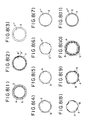
- Figs. 1(1) and (2) illustrate a mother particle a to which only child particles b or both of child particles b and different child particles c are previously adhered by static electricity.
- the child particles b are enbedded in the mother particle a or fixed to the mother particle a as shown in Figs. 1(3) to (5) and the child particles b and c are fixed to the mother particle in the form of a single layer or plural layers by changing the order of supply of the child particles b and c , as shown in Figs. 1(6) to (8).
- the valve 9 is moved to a position shown by chain line to open the valve 9 and the processed powder is exhausted. That is, the processed powder is exhausted from the impact chamber 18 and the circulating circuit 13 in a short time (several seconds) by centrifugal force (if the processed powder receives the centrifugal force, the valve 9 may be formed at another place) and sucking force of the wind exhausting device 25 and is guided through the shoot 20 to a powder collecting device such as the cyclone 21 and the bag filter 23. The guided powder is collected thereto and exhausted outside through the rotary valves 22 and 24.
- the valve 9 is closed immediately. Then, a constant quality of powder to be processed is fed to the impact chamber through the metering feeder 16 again. The powder is subjected to the fixing operation in the same manner so that the processed powder is manufactured successively.
- the fixing operation of powder in one operation is continuously controlled by the time control device 31 in which time required to process the powder has been established previously in relation to operating time of associating devices.
- the powder impact apparatus of Fig. 2 can be used as a one pass type continuous processing system.
- the circulating inlet 19 is closed and the valve 9 is opened. Then, the powder to be processed may be fed from the hopper 15 continuously.
- the collision ring 8 and the circulating circuit 13 are formed in jacket structure and a temperature condition suitable for the fixing operation of powder can be set by means of various heating agent and refrigerant.
- auxiliary blades can be mounted to the rotating plate 4 or a centrifugal type plate fan, for example, can be disposed on the way of the circulating circuit 13 so that forced power can be added to circulating current. More particularly, if air quality for circulation is increased, the number of times of circulation in unit time is increased. Accordingly, since the number of times of collision of powder is also increased, time required for the fixing operation can be reduced. Further, the method according to the present invention can be not only implemented by the apparatus provided with the circulating circuit but also by that having a structure in which the circulating circuit is removed in Figs. 2 and 3.
- Fig. 4 shows an embodiment in which inert gas is used in the powder impact apparatus according to the present invention.
- like elements to that of Figs. 1 and 2 are designated by like numerals and description thereof is omitted.
- numeral 26 denotes a valve disposed below the hopper 14 to feed raw material
- numeral 27 denotes a valve coupled with an opening formed in the shoot 15 to supply inert gas
- numeral 28 denotes an inert gas supply source
- numeral 29 denotes a path for supplying inert gas.
- the circulating circuit 13 is provided within the casing 1.
- valve 26 for feeding raw material is closed and the valve 9 is opened.
- valve 27 for supplying inert gas is opened so that the impact chamber 18 and the circulating circuit 13 are filled with inert gas.
- the filling operation of inert gas in the impact chamber and the circulating circuit prior to the fixing operation is generally terminated within a few minutes.
- valve 26 is opened immediately so that previously measured powder is fed through the shoot 15 to the impact chamber 18. After supply of powder, the valve 26 is closed immediately. In response to the closure of the valve 26, the metering feeder 16 measures powder for the next operation and supplies it to the hopper 14.
- the powder is then subjected to the impact operation together with inert gas in the same manner as in the above embodiment of Fig. 2.
- the powder is settled while circulating in the circuit 13 and maintaining in sufficient contact with inert gas.
- the valves 9 and 27 are then opened and the processed powder is exhausted from the impact chamber 18 and the circulating circuit 13 to shoot 20.
- the impact chamber 18 and the circulating circuit 13 are filled with new inert gas.
- the exhausted powder is processed in the same manner as in the embodiment of Fig. 2.
- the powder impact apparatus of Fig. 4 can be used as a one pass type continuous processing system.
- the circulating circuit 13 of Fig. 4 is closed and the valves 26, 27 and 9 are opened.
- the powder to be processed may be fed from the hopper 14 continuously at a rate of constant quality.
- inert gas from the outlet of the wind exhausting device 25 of Fig. 2 is returned to the shoot 15, a quality of used inert gas can be reduced economically.
- the surface quality improving method of solid (powder) particles and the apparatus thereof according to the present invention are characterized by strong impact of the impactor mechanism forming the impact striking means to fine powder particles, utilization of difference of hardness between mother particles and child particles, magnitude of impact given to the whole surface of mother particles having a fixed shape, and the number of times of impact which can be adjusted.
- child particles are formed on surface of the mother particle made of various material in the form of a single layer made of a single component of child particles and made of two components and in the form of a plurality of layers made of one or more components of child particles.
- the pre-processor such as various mixers and an electric mortar is not used and mother particle powder and child particle powder measured separately are supplied to the impact chamber directly so that the fixing operation of child particles to surface of mother particles can be made.
- the surface quality improving apparatus of solid particles according to the present invention includes the impact chamber and the circulating circuit having very simple structure and when the front cover is opened the rotating plate 4 can be removed to make disassembly easily. Accordingly, maintenance and cleaning in the apparatus can be made very easily.
- the apparatus can be avoid mixture of alien material upon change of a product and can be provided to improve quality of surface of powder material of wide range.
- inert gas when used, inert gas is used efficiently and quality of used inert gas can be minimized.
- the powder impact apparatus of Fig. 2 including eight plate type impact pins mounted on the periphery of the rotating plate and having an outer diameter of 235 mm and the circulating circuit having a diameter of 54.9 mm was used.
- Fig. 5 shows photographs taken by a scanning electon microscope of improved powder obtained by the Example 1 (T-3 and T-4).
- Representative mother particle powder uses various powder shown in the first embodiment.
- representative child particle powder has a diameter of about 0.01 ⁇ m to 10 ⁇ m and contains nylon powder, polyethlene powder, acryl powder, styrene powder, polypropylene powder, ABS powder, polyvinyl alcohol, gelatin, various wax, sulfur and organic substance, inorganic substance and metal such as alloy having low melting point.
- nylon powder polyethlene powder
- acryl powder acryl powder
- styrene powder polypropylene powder
- ABS powder polyvinyl alcohol
- gelatin polyvinyl alcohol
- various wax sulfur and organic substance, inorganic substance and metal such as alloy having low melting point
- Combination of sizes of a diameter and magnitude of hardness is the same as the first embodiment.
- Impact striking means uses the same impactor as the first embodiment shown in Figs. 2 to 4 and operation is made in the simmilar manner.
- Impact operation is continuously repeated many times in a short time, and child particles are embedded or firmly fixed to surface of mother particles. Further, child particles receive thermal energy by impact operation to soften and melt in a short time, so that the whole or part of child particles fixed to surface of one mother particle are melted and united to each other.
- the series of impact operation that is, the softening, melting and fixing operations of child particles to surface of mother particle are continued until the whole surface of mother particle becomes a desired melted and united condition.
- Fig. 6 shows models.
- mother particles and child particles are not limited to sphere.
- Figs. 6(1) and (2) illustrate mother particle (a and a ⁇ ) to which child particles (b and b ⁇ ) are adhered previously by static electricity.
- the mother and child particles are subjected to the impact striking operation and surface of child particles is softened and melted as shown in Figs. 6(3) to (5).
- Union or combination between child particles is caused at partial surface or over the whole surface of mother particle so that child particles are settled to surface of mother particle.
- child particles (b, c) different from each other are fixed to mother particle a in the form of a single layer or multiple layers depending on combination of various child particles and supply order of child particles.
- child particles are fixed to surface of mother particle made of various material in the form of a single particle layer composed of a single component of child particles or composed of two component of child particles, in the form of a micro capsule formed by covering mother particle in the form of film with child particle and a plurality of layers composed of one component or more of child particles.
- the child particles may be any shape such as sphere, indeterminate form, fiber shape and the like.
- the surface of mother particle is not limited to smooth surface and may be any shape having, for example, various sizes of uneven portions, holes or grooves.
- the fixing operation may be made in the same manner as the first embodiment.
- the same apparatus as the example 1 is used.
- powder of nylon 12 having surface improved uniformly and stably by polymethyl methacrylate was obtained.
- Fig. 7 shows photographs taken by a scanning electron microscope of improved powder obtained by the example 2.
- Fig. 7(1) shows child particles adhered to surface of mother particle
- Figs. 7(2), (3) and (4) show particles improved under conditions of the implementation Nos. T-11, T-12 and T-13, respectively.
- representative mother particle powder processed by the method of the present invention has a diameter of about 0.1 ⁇ m to 100 ⁇ m and contains inorganic substances such as calcium carbonate, kaolin, alumina, silica, glass bead and titanium dioxide, metal and metal compound such as copper, lead, zinc, tin and iron, organic substance composite high molecule material such as epoxy powder, nylon powder, polyethylene powder and polystyrene powder, and organic substance natural material such as starch, cellulose and silk powder.
- inorganic substances such as calcium carbonate, kaolin, alumina, silica, glass bead and titanium dioxide, metal and metal compound such as copper, lead, zinc, tin and iron, organic substance composite high molecule material such as epoxy powder, nylon powder, polyethylene powder and polystyrene powder, and organic substance natural material such as starch, cellulose and silk powder.
- representative metal child particle powder (containing particle in the form of needle and thread) has generally a diameter of about 0.01 ⁇ m to 10 ⁇ m and contains fine particle powder formed of gold, silver, copper, zinc, tin, iron, lead, stainless steel, nickel, aluminium, titanium and cadmium, and powder oxide and compound powder thereof.
- both particles are not limited to the above materials and are applicable to combined components of various materials used in industries such as chemical industry, electrical industry, magnetic industry and varous other industries dealing with cosmetics, paints, printing ink, toner, color material, fiber, medicine, foods, rubber, plastic, ceramic and the like.
- mother particles having large diameter and child particles having small diameter There are generally used mother particles having large diameter and child particles having small diameter. However, relation of the diameter between mother particles and child particles is reversed depending on combination of largeness of particles.
- Impact striking means uses the same impactor as in the first embodiment shown in Figs. 2 to 4 and the sililar operation is made. Further, there is a case where child particles are adhered to surface of mother particles while using a small quality of water or material forming a binder such as various organic solvent.
- Impact operation is continuously repeated many times in a short time so that metal child particles are strongly beaten out to surface of mother particle. Further, the metal child particles are firmly fixed to surface of mother particles in a short time by receiving thermal energy due to impact operation.
- the series of impact operation that is, the beating and fixing operation of metal child particles to surface of mother particle is continued until surface of mother particle becomes desired beaten and fixed condition locally or wholly. Since gas (containing air and inert gas) having large quality as compared with all the capacity of the impact chamber and the circulating system is circulated in the system, particle (that is, mother particles and metal child particles) circulating in the system together with gas receives very large number of times of impact in a very short time.
- the time required to the beating and fixing operation is as very short as several seconds to several minutes even if containing supply time of powder to be processed, although depending on quality of powder to be processed at one time.
- metal particles (b, b ⁇ ) are adhered to mother particle with static electricity or small quality of binder previously.
- the mother particles and child particles are subjected to the impact operation to beat out surface of metal child particles as shown in Fig. 6(3) to (5) so that metal child particles are adhered or overlapped to each other partially or wholly and metal child particles are fixed to surface of mother particle.
- metal child particles (b, c) different from each other can be beaten and fixed to surface of mother particle in a single layer and multiple layers depending on combination of various metal child particles and supply order thereof.
- metal child particles may be fixed to surface of mother particle partially and locally, if thermal treatment is used secondarily, if inert gas is used, or like, the operation may be made in the same manner as the embodiment.
- the method of beating and fixing metal particles to surface of solid particles according to the present invention is characterized by adjustability of the magnitude of impact and the number of times of impact given to metal particles adhered to the whole surface of mother particle having a fixed shape under a condition where fine powder particles are perfectly dispersed in air in the apparatus by utilizing strong impact of the impactor forming the impact striking means to fine powder particles. Since proper impact can be given to individual fine powder particles simultaneously while preventing perfectly various fine powder particles having a diameter of the order of micron and tendency of cohering with each other from being adhered to each other, the improved powder having uniform quality and excellent color and brightness peculiar to metal can be produced in a short time.
- metal child particles are beaten out and fixed to mother particles of various material in a single layer made of a component of metal child particles or two or more components of metal child particles, in the form of micro capsule covering mother particle like film, and in plural layers made of one or more components of metal particles.
- the metal particles may be any shape such as sphere, indeterminate form, fiber shape and the like.
- the metal child particles are beaten out and fixed to the mother particles made of combination of various powder material so that quality of surface of mother particle is improved, and functional composite or hybrid having uniform and stable characteristics can be produced effectively in a very short time.
- representative mother particle powder uses various powder described in the third embodiment.
- representative child particle powder contains inorganic matter such as calcium carbonate, kaoline, alumina and titanium dioxide, metal and metal compound such as copper, zinc, tin and iron, organic matter such as nylon, acryl, styrene and ABS in the form of a suspension, emulsion, sol and gel and having a diameter of about 0.001 ⁇ m to 10 ⁇ m.
- Melting material for forming a film contains wax, paraffin, rosin, various cellulose, oils and fats, gelatin, sugar, rubber, starch, starch inductor, silicon, titanium dioxide, copper, silver and various inorganic salts in the form of melted liquid.
- Figs. 9 and 10 shows an impactor used in the embodiment, in which numerals 32a, 32b and 32c denote, for example, spray nozzles for supplying liquid, that is, suspension or solution to surface of mother particle, numeral 33 denotes supply pipes of the liquid, numeral 34 denotes supply pumps of the liquid, numeral 35 denotes a reservoir of the liquid, numeral 36 denotes valves of the liquid which open and close automatically and manually.
- numerals 32a, 32b and 32c denote, for example, spray nozzles for supplying liquid, that is, suspension or solution to surface of mother particle
- numeral 33 denotes supply pipes of the liquid
- numeral 34 denotes supply pumps of the liquid
- numeral 35 denotes a reservoir of the liquid
- numeral 36 denotes valves of the liquid which open and close automatically and manually.
- Other elements are the same as those of the apparatus shown in the above embodiment and are designated by like numerals and description is omitted.
- Circulation cycle of air current are formed in the apparatus in the same manner as in the above embodiment.
- a constant quality of powder to be processed that is, mother particles are supplied to the hopper 14 from the metering feeder 16 in a short time.
- solution such as suspension, emulsion, sol and gel containing small particles for surface quality improvement or solution of material for surface quality improvement is supplied from the nozzles 32a, 32b and 32c.
- Supply quality of the solution is set by, for example, established pressure of the pump 34 and opening and closing time of the automatic valve.
- the powder to be processed is supplied from the hopper 14 through the shoot 15 to impact chamber 18 and the solution supplied from the nozzles 32a, 32b and 32c is also supplied to the impact chamber 18.
- the powder particles and solution supplied to the impact chamber 18 receive momentary striking operation by multiple impact pins 5 mounted on the rotating plate 4 which rotates at a high speed and collide against the collision ring 8 provided peripherally so that surfaces of mother particles are compressed strongly.
- the powder is returned through the circulating circuit 13 to the impact chamber 18 again together with a current of the circulating gas and are struck again.
- the impact operation is continuously repeated proper times in a short times.
- solution is uniformly adhered to surface of mother particles and the adhered solution receives thermal energy caused by impact operation.
- the solution containing child particles is dried in a short time and at the same time child particles left to surface of mother particles are firmly adhered to mother particles.
- solid matter in solution is also fixed to surface of mother particles.
- Solution having high temperature upon supply is reversely cooled and melted material forms film on surface of mother particles.
- the series of impact operation that is, fixing operation of child particles to surface of mother particle or film forming operation of melted material is continued until the whole surface of mother particle becomes desired condition.
- Fig. 8 shows models.
- mother particles and child particles are not limited to sphere.
- Figs. 8(1) and (2) illustrate mother particles (a, a ⁇ ) with child particles (b, b ⁇ ) adhering to the mother particles together with various solutions (c), and
- Fig. 8(3) illustrates mother particles (a ⁇ ⁇ ) to which solution (d) of various materials adheres.
- the mother particles, child particles and solutions are subjected to the impact operation.
- the solution (c) containing child particles is dried and solution is dried or cooled so that at the same time child particles or film is firmly fixed to surface of mother particles.
- the child particles (b, e) different from each other are fixed to surface of the mother particles (a) in a single and multiple layers and multiple layers of films (d, f) can be fixed to surface of mother particles (a ⁇ ⁇ ) depending on combination of various child particles and supply order as shown in Figs. 8(8) to (11).
- Fig. 11 shows an embodiment of the powder impactor according to the present invention in which inert gas is used. Like elements to those of the above embodiment are designated with like numeral and description thereof is omitted.
- valve 26 for feeding raw material is closed and the valve 9 is opened.
- valve 27 for supplying inert gas is opened so that the impact chamber 18 and the circulating circuit 13 are filled with inert gas.
- the filling operation of inert gas in the impact chamber and the circulating circuit prior to the fixing operation is generally terminated within a few minutes.
- valve 26 is opened immediately so that previously measured powder is fed through the shoot 15 to the impact chamber 18. At the same time or after a constant time, liquid is supplied from the nozzles 32b and 32c. After supply of powder, the valve 26 is closed immediately. In response to the closure of the valve 26, the metering feeder 16 measures powder for the next operation and supplies it to the hopper 14.
- the powder is then subjected to the impact operation together with inert gas in the same manner as in the above embodiments and is processed in the same manner as in the above embodiments.
- the resultant effects are substantially identical.
- child particles or film forming material is fixed to surface of mother particle of various material in a single layer made of one component or two or more components of child particles, in the form of micro capsule in which mother particles are covered with film, and in plural layers made of one or more components of child particles or film forming material.
- child particles or film forming material is firmly fixed to mother particles composed of combination of various powder material and liquid so that quality of surface of mother particles is improved, and functional composite or hybrid powder having uniform and stable characteristics can be produced effectively in a very short time.
- a powder impactor of Fig. 9 including eight plate type impact pins mounted in the periphery of the rotating plate and having an outer diameter of 235 mm and circulating circuit having a diameter of 54.9 mm is used.
- the powder impactor of Fig. 9 including twelve plate type impact pins mounted in the periphery of the rotating plate and having an outer diameter of 235 mm and circulating circuit having a diameter of 54.9 mm is used.
- the improving operation was effected under the following filming conditions.
- the outer wall of the impact chamber and the circulating pipe was formed in jacket structure in order to reduce a temperature of circulating air to 65 °C or less and cooling water having a temperature of 14°C was used as refrigerant. Consequently, temperature of obtained improved powder was 54°C.
- Representative mother particle powder of which surface can be processed by the method of the present invenion has a diameter of about 0.1 ⁇ m to 100 ⁇ m and surface formed in various shape with uneven portions, holes and grooves and is formed of organic matter, inorganic matter and metal such as nylon powder, polyethylene powder, acryl powder, styrene powder, ABS powder, polypropylene powder, gelatin, various wax, sulfur, copper powder and silver powder.
- Representative child particle powder has a diameter of about 0.01 ⁇ m to 10 ⁇ m and is formed of pigment such as titanium dioxide, carbon and iron oxide, high molecule material such as epoxy powder, nylon powder and acryl powder, metal such as tin, silver and copper, natural material such as starch, cellulose, silk powder and ceramics and various powder perfume.
- the present invention is not limited to the above materials and is applicable to combined components of various materials used in industries such as chemical industry, electrical industry, magnetic industry and various other industries dealing with cosmetics, paints, printing ink, toner, color material, fiber, medicine, foods, rubber, plastic, ceramic and the like.
- the impact operation is continuously repeated proper times in a short time.
- Surface of mother particles, particularly projections of mother particles receive thermal energy caused by impact operation so that projections are soften, melted and transformed and child particles are embedded in mother particles.
- film of mother particles is formed on surface of mother surface.
- the series of impact operation is continued until the whole surface of mother particles becomes desired melted state.
- the time required to improve quality of surface is generally very short time of several seconds to several minutes even if containing supply time of powder in the same manner as in the above embodiments.
- Fig. 12 shows models.
- a represents a mother particle having a surface formed in various shape of uneven portions or with holes and grooves and b represents child particles.
- Fig. 12(1) shows mother particle and child particles both being not adhered to each other, and
- Fig. 12(2) shows mother particle with child particles being adhered to the mother particle.
- portions, that is, projections of the mother particle are softened, melted or transformed and child particles are embedded into mother particle as shown in Figs. 12(3) and (4).
- the embedded child particles are not limited to a single component of child particles but can contain two or more components of child particles.
- the subsequent operation is the same as that of the above embodiment.
- Child particles may be fixed to surface of mother particle partially and locally, if thermal treatment is used secondarily, if inert gas is used, or like, the same operation as in the first to third embodiments may be made.
- the surface quality improving method of solid particle powder accoring to the present invention is characterized by strong impact of the impactor mechanism forming impact striking means to fine powder particles and embedment of child particles into mother particle by utilization of impact in view of surface shape of mother particle.
- the powder impactor of Fig. 2 including eight-plate-type impact pins mounted in the periphery of the rotating plate and having an outer diameter of 235 mm and the circulating circuit having a diameter of 54.9 mm was employed.
- the particles adhered to each other were processed by the processing apparatus under the conditions of rotational number of 6540 rpm, powder supply quality of 120g and operating time of 2 minutes.
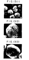
- Surface quality improved powder in which embedded acetylene black (child particles) into nylon particle (mother particle) is further covered over surface thereof with nylon 6 was obtained.
- Fig. 13 shows photographs taken by a scanning electron microscope of powder sample used in the embodiment, in which Fig. 13(1) shows porous mother particles, Fig. 13(2) shows mother particle with child particles adhering to mother particle, and Fig. 13(3) shows mother particle in which child particles are embedded.
- the surface quality improving operation in which child particles are embedded into mother particle composed of combination of various powder materials by utilizing shape of surface of mother particle is performed so that functional composite or hybrid powder having uniform and stable characteristics can be obtained efficiently in a very short time.
- the spheroidizing operation of fine powder is made in order to prevent lumping of solid particles and to improve dispersion and fluidity.
- the operation has been made by putting material into an agitator of various mixer type and ball mill type to agitate the material for a long time (generally, several hours to several tens hours) and by giving friction force and compression force caused by agitation.
- the embodiment provides the method in which fine solid particles having different diameters and shape as shown by a phothgraph (1) of Fig. 14 can be made to spherical particles having uniform roundness as shown by a photograph (2) of Fig. 14 by using mechanical impact means and if necessary using thermal means as auxiliary means in a very short time.
- the gist thereof resides in the method of spheroidizing indeterminate fine solid particles (powder) by using impact striking means.
- Representative powder to be spheroidized has a diameter of about 0.1 ⁇ m to 100 ⁇ m and is formed of organic matter such as epoxy powder, nylon powder, polyethylene powder, polystyrene powder, cellulose and silk powder, inorganic matter and metal such as titanium oxide, graphite, zinc powder, nickel, copper, lead and iron.
- organic matter such as epoxy powder, nylon powder, polyethylene powder, polystyrene powder, cellulose and silk powder
- inorganic matter and metal such as titanium oxide, graphite, zinc powder, nickel, copper, lead and iron.
- the powder is not limited to the above materials and is applicable to combined components of various materials used in industries such as chemical industry, electrical industry, magnetic industry and various other industries dealing with cosmetics, paints, printing ink, toner, color material, fiber, medicine, foods, rubber, plastic, ceramic and the like.
- the core when the core is formed by various materials and fine particles having characteristic different from that of the core particle are fixed to surface of the core particle or are formed in film on surface of the core particle, that is, when the surface quality improving operation is made, if the core material has indeterminate shape (generally, diameter thereof is not uniform), the spheroidizing operation can be made at the same time as the surface quality improving operation.
- raw material to be spheroidized is supplied to the hopper 14 and the same operation as the above embodiments is made.
- the impact operation is continuously repeated proper times in a short time and indeterminate powder particles are spheroidized.
- the series of impact operation that is, spheroidizing operation is continued until the whole surface of fine powder particles becomes uniform sphere or substantially round.
- the spheroidizing operation is terminated in a very short time in the same manner as the embodiments.
- the particles are spheroidized partially and locally, if thermal treatment is used secondarily, if inert gas is used, or the like, the same operation as the above embodiments may be made.
- Fig. 14 shows photographs taken by a scanning electron microscope of powder particles before and after spheroidization under conditions of the example 7 (T-33).
- the magnitude of impact and number of times thereof for giving impact to the whole surface of powder particles having different diameters and shapes in the state where fine powder particles are dispersed perfectly in air of the system by utilizing strong impact of the impactor forming impact striking means to the fine particles can be adjusted properly.
Landscapes
- Chemical & Material Sciences (AREA)
- Chemical Kinetics & Catalysis (AREA)
- Organic Chemistry (AREA)
- Engineering & Computer Science (AREA)
- Mechanical Engineering (AREA)
- Dispersion Chemistry (AREA)
- Glanulating (AREA)
Claims (20)
- Procédé pour améliorer la qualité de surface de particules solides en frappant la surface desdites particules solides avec des fines particules de taille plus petites que celles desdites particules solides, en utilisant une chambre de collision et une plaque tournante présentant une pluralité d'ergots d'impact s'étendant depuis sa surface, ladite plaque tournante étant disposée de façon à pouvoir tourner à l'intérieur de ladite chambre de collision, procédé qui comporte l'introduction desdites particules solides présentant un diamètre d'environ 0,1 µm à 100 µm, et de particules plus petites présentant un diamètre d'environ 0,01 µm à 10 µm dans ladite chambre de collision, la mise en rotation de la plaque tournante à une vitesse périphérique de 50 à 160 m/s pour créer un flux gazeux à haute vitesse à l'intérieur de ladite chambre de collision, ledit flux gazeux servant à guider et à faire circuler lesdites particules solides et lesdites particules fines plus petites à l'intérieur de ladite chambre de collision pour former un cycle de circulation à très haute vitesse et à fréquence de circulation élevée de façon à ce qu'on provoque l'impact des particules fines plus petites et de façon à ce que les particules fines plus petites soient fixées sur la surface des particules solides.
- Procédé selon la revendication 1, selon lequel on dispose un anneau de collision sur les parois de la chambre de collision et un circuit à auto-circulation guide et fait circuler au moins une partie du flux gazeux circulant contenant les particules solides et les particules plus fines depuis la chambre de collision au voisinage de l'anneau de collision et renvoie le flux gazeux vers la chambre de collision au voisinage du centre de la plaque tournante, de façon à constituer un cycle de circulation à très haute fréquence, de telle sorte que l'énergie d'impact générée par les ergots d'impact, l'anneau de collision et la fréquence de circulation provoquent l'inclusion des particules fines plus petites dans la surface des particules solides.
- Procédé selon la revendication 2, dans lequel l'énergie thermique est générée par l'énergie d'impact produite par la plaque tournante.
- Procédé selon la revendication 3, dans lequel les particules fines plus petites et les particules solides sont fondues ensemble par un chauffage auxiliaire.
- Procédé selon la revendication 4, dans lequel les particules fines plus petites sont des particules solides de tailles plus petites que celles des particules solides.
- Procédé selon la revendication 1, dans lequel les particules fines plus petites viennent frapper de façon forcée la surface des particules solides de façon à y être fixées.
- Procédé selon la revendication 1, dans lequel les particules fines plus petites sont tout d'abord rendues adhérentes à la surface des particules solides.
- Procédé selon la revendication 1, dans lequel on utilise un liquide de séchage ou de refroidissement sur la surface des particules solides sur laquelle les particules fines plus petites ont été tout d'abord fixées.
- Procédé selon la revendication 1, dans lequel la force d'impact est appliquée au liquide de séchage ou de refroidissement pour fixer un film de particules fines plus petites contenues dans le liquide à la surface des particules solides, ledit liquide étant fourni à la chambre de collision pendant qu'on applique la force d'impact aux particules fines plus petites par les particules solides, de telle sorte que ledit liquide y adhère.
- Procédé selon la revendication 1, dans lequel les particules fines plus petites sont fixées à la surface des particules solides par amollissement et fusion desdites particules fines plus petites en utilisant la force d'impact lors de la frappe.
- Procédé selon la revendication 1, dans lequel les particules solides présentent des surfaces formées par des cavités et des formes non régulières, des trous ou des rainures, et ladite force d'impact par frappe est utilisée pour amollir, fondre et transformer les particules solides, de telle sorte que les particules fines plus petites y soient fixées.
- Procédé selon la revendication 1, dans lequel on introduit de plus un gaz inerte dans la chambre de collision.
- Appareil pour améliorer la qualité de surface des particules solides, selon la revendication 1, comprenant une plaque tournante (4) formée avec une pluralité d'ergots d'impact (5) le long de sa circonférence, et un anneau de collision (8) disposé le long de la surface extérieure desdits ergots d'impact (5) qui comporte ladite plaque tournante (4) destinée à tourner à une vitesse périphérique de 50 à 160 m/s, une chambre de collision (18) entourée par l'anneau de collision (8) et formée à la circonférence de ladite plaque tournante (4) et un circuit d'autocirculation (13) pour guider et faire circuler un flux d'air généré dans ladite chambre de collision (18) suite à la rotation de ladite plaque tournante (4) et aussi un groupe de particules solides que l'on fait se déplacer ensemble avec ledit flux d'air, ledit circuit (13) d'autocirculation étant disposé sur ladite chambre de collision (18), une ouverture latérale dudit circuit (13) d'autocirculation étant ouverte sur une partie dudit anneau de collision (8) et l'ouverture de l'autre côté étant positionnée sur un couvercle frontal (3) à proximité du centre de ladite plaque tournante (4).
- Appareil selon la revendication 13, dans lequel la surface de collision est un anneau de collision (4) disposé le long de la surface intérieure de la chambre de collision (18), ledit anneau de collision (8) présentant une surface rainurée vis à vis des ergots d'impact (15).
- Appareil selon la revendication 13, dans lequel les moyens pour retirer les particules solides de la chambre de collision (18) comprennent une valve d'ouverture et de fermeture (9) associée fonctionnellement aux moyens servant de conduit (20).
- Appareil selon la revendication 15, dans lequel une pompe d'échappement (25) communique avec les moyens servant de conduit (20).
- Appareil selon la revendication 13, dans lequel un dispositif de contrôle de durée (31) est connecté fonctionnellement avec les moyens d'entrée (15) et avec les moyens (9, 10, 11) pour retirer lesdites particules solides de la chambre de collision (18).
- Appareil selon la revendication 13, dans lequel des moyens (27, 28, 29) sont prévus pour introduire un gaz supplémentaire dans la chambre de collision (18).
- Appareil selon la revendication 13, dans lequel les moyens d'entrée comprennent une pluralité de moyens d'entrée (32a, 32b, 32c) pour introduire des particules solides ou des particules solides suspendues dans un milieu fluide dans la chambre de collision (18) et/ou dans les moyens (13) servant de circuit d'autocirculation.
- Appareil selon la revendication 13, dans lequel des moyens de chauffage sont prévus associés à la chambre de collision (18) et/ou aux moyens (13) servant de circuit d'autocirculation.
Applications Claiming Priority (12)
| Application Number | Priority Date | Filing Date | Title |
|---|---|---|---|
| JP223158/85 | 1985-10-07 | ||
| JP60223158A JPS6283029A (ja) | 1985-10-07 | 1985-10-07 | 固体粒子の表面改質方法 |
| JP280272/85 | 1985-12-13 | ||
| JP60280272A JPS62140636A (ja) | 1985-12-13 | 1985-12-13 | 固体粒子表面の成膜方法 |
| JP61064317A JPS62221434A (ja) | 1986-03-22 | 1986-03-22 | 微小固体粒子の球形化処理方法 |
| JP64317/86 | 1986-03-22 | ||
| JP61094172A JPS62250942A (ja) | 1986-04-23 | 1986-04-23 | 固体粒子表面への金属の延展固定方法 |
| JP94172/86 | 1986-04-23 | ||
| JP104527/86 | 1986-05-07 | ||
| JP61104527A JPS62262737A (ja) | 1986-05-07 | 1986-05-07 | 固体粒子の表面改質方法とその装置 |
| JP140993/86 | 1986-06-17 | ||
| JP61140993A JPS62298443A (ja) | 1986-06-17 | 1986-06-17 | 固体粒子の表面改質方法 |
Publications (3)
| Publication Number | Publication Date |
|---|---|
| EP0224659A2 EP0224659A2 (fr) | 1987-06-10 |
| EP0224659A3 EP0224659A3 (en) | 1989-02-08 |
| EP0224659B1 true EP0224659B1 (fr) | 1992-12-02 |
Family
ID=27550974
Family Applications (1)
| Application Number | Title | Priority Date | Filing Date |
|---|---|---|---|
| EP86112228A Expired - Lifetime EP0224659B1 (fr) | 1985-10-07 | 1986-09-04 | Méthode pour améliorer la qualité de la surface de particules solides et appareil à cet effet |
Country Status (3)
| Country | Link |
|---|---|
| US (1) | US4915987A (fr) |
| EP (1) | EP0224659B1 (fr) |
| DE (1) | DE3687219T2 (fr) |
Families Citing this family (62)
| Publication number | Priority date | Publication date | Assignee | Title |
|---|---|---|---|---|
| JPS6463035A (en) * | 1987-09-02 | 1989-03-09 | Soken Kagaku Kk | Powdery body having compound structure and production thereof |
| JP2686638B2 (ja) * | 1988-03-17 | 1997-12-08 | 石原産業株式会社 | 抗菌性粉末及びその製造方法 |
| US5006368A (en) * | 1988-10-19 | 1991-04-09 | The Dow Chemical Company | Plastic particle coated with processing aid and method of coating |
| JPH02256065A (ja) * | 1988-12-19 | 1990-10-16 | Konica Corp | 磁性トナー |
| US5056715A (en) * | 1990-02-21 | 1991-10-15 | Pfizer Inc. | Apparatus for mixing and spraying a slurry |
| CA2038432C (fr) * | 1990-03-19 | 1995-05-02 | Tadashi Kamimura | Compose fritte et methode de production connexe |
| JPH03274205A (ja) * | 1990-03-26 | 1991-12-05 | Isuzu Motors Ltd | 局部硬化焼結体とその製造方法 |
| DE4109979C2 (de) * | 1990-03-28 | 2000-03-30 | Nisshin Flour Milling Co | Verfahren zur Herstellung beschichteter Teilchen aus anorganischen oder metallischen Materialien |
| JP2941081B2 (ja) * | 1991-03-26 | 1999-08-25 | 株式会社奈良機械製作所 | 結晶性有機化合物の非晶質割合の増加と再結晶化を抑制する方法 |
| CA2069074C (fr) * | 1991-05-23 | 2002-01-08 | Yuzo Itakura | Farine de bois et methode de production |
| US5312648A (en) * | 1991-09-05 | 1994-05-17 | Technalum Research, Inc. | Method for coating particles using counter-rotating disks |
| JP3036184B2 (ja) * | 1991-11-02 | 2000-04-24 | ミノルタ株式会社 | 静電潜像現像用トナー |
| JP2835796B2 (ja) * | 1992-02-06 | 1998-12-14 | メルク・ジヤパン株式会社 | 新規な薄片状顔料 |
| JPH05220375A (ja) * | 1992-02-12 | 1993-08-31 | Nara Kikai Seisakusho:Kk | 固体粒子の表面改質方法と装置 |
| US5372845A (en) * | 1992-03-06 | 1994-12-13 | Sulzer Plasma Technik, Inc. | Method for preparing binder-free clad powders |
| US5628945A (en) * | 1992-08-03 | 1997-05-13 | Riman; Richard E. | Multicomponent powder mixing process and compositions produced thereby |
| US5385789A (en) * | 1993-09-15 | 1995-01-31 | Sulzer Plasma Technik, Inc. | Composite powders for thermal spray coating |
| US5660934A (en) * | 1994-12-29 | 1997-08-26 | Spray-Tech, Inc. | Clad plastic particles suitable for thermal spraying |
| FR2732674B1 (fr) * | 1995-04-10 | 1997-05-09 | Alcatel Fibres Optiques | Procede et dispositif de spheroidisation de granules de silice |
| JP2957492B2 (ja) * | 1996-03-26 | 1999-10-04 | 合資会社亀井鉄工所 | ワーク表面の研削方法 |
| US5736200A (en) * | 1996-05-31 | 1998-04-07 | Caterpillar Inc. | Process for reducing oxygen content in thermally sprayed metal coatings |
| JP3390863B2 (ja) * | 1997-12-01 | 2003-03-31 | 株式会社奈良機械製作所 | 複合固体粒子とその製造方法 |
| US6264861B1 (en) | 1998-08-05 | 2001-07-24 | Xeikon Nv | Method for producing rounded polymeric particles |
| US6197369B1 (en) * | 1999-09-30 | 2001-03-06 | New Jersey Institute Of Technology | Method of particle coating |
| US6602556B2 (en) * | 2001-08-28 | 2003-08-05 | Saint-Gobain Abrasives Technology Company | Ceramic shell thermal spray powders and methods of use thereof |
| US6680279B2 (en) | 2002-01-24 | 2004-01-20 | General Motors Corporation | Nanostructured catalyst particle/catalyst carrier particle system |
| WO2004062799A1 (fr) * | 2003-01-09 | 2004-07-29 | Showa Denko K.K. | Particules composites, leur procede de production et leur utilisation |
| US6956007B2 (en) * | 2003-08-25 | 2005-10-18 | General Motors Corporation | Noble metal catalyst |
| US20050123759A1 (en) * | 2003-12-04 | 2005-06-09 | Roger Weinberg | Additive-coated resin and method of making same |
| JP2005246193A (ja) * | 2004-03-03 | 2005-09-15 | Konica Minolta Holdings Inc | 複合皮膜の製造方法、溶射用粒子、複合皮膜及びそれを用いた放射線画像変換パネル |
| DE102006025848A1 (de) * | 2006-03-29 | 2007-10-04 | Byk-Chemie Gmbh | Herstellung von Nanopartikeln, insbesondere Nanopartikelkompositen, ausgehend von Pulveragglomeraten |
| KR20070108798A (ko) * | 2006-05-08 | 2007-11-13 | 최길배 | 나노입자 및 메조입자로 표면 개질된 중합체 거대입자,이를 이용한 나노입자-고분자 복합소재, 및 이들의제조방법 |
| ITMI20070089A1 (it) | 2007-01-22 | 2008-07-23 | Colheng S A S | Granulo di polimero termoplastico e/o termoindurente colorato e/o additivato e relativo procedimento di colorazione e/o additivazione |
| WO2009027193A1 (fr) * | 2007-08-27 | 2009-03-05 | Borealis Technology Oy | Appareillage et procédé servant à produire des pastilles de polymère |
| JP4615554B2 (ja) * | 2007-10-04 | 2011-01-19 | 株式会社ブリヂストン | 表示媒体用粒子およびそれを用いた情報表示用パネル |
| JP4572246B2 (ja) * | 2008-05-29 | 2010-11-04 | シャープ株式会社 | トナー、現像剤、現像装置および画像形成装置 |
| JP4512657B2 (ja) * | 2008-05-30 | 2010-07-28 | シャープ株式会社 | トナーの製造方法およびトナー、現像剤、現像装置ならびに画像形成装置 |
| JP4660580B2 (ja) * | 2008-09-11 | 2011-03-30 | シャープ株式会社 | トナーの製造方法およびトナー、現像剤、現像装置ならびに画像形成装置 |
| JP4662568B2 (ja) * | 2008-09-29 | 2011-03-30 | シャープ株式会社 | トナーの製造方法およびトナー、現像剤、現像装置ならびに画像形成装置 |
| JP4718594B2 (ja) * | 2008-10-28 | 2011-07-06 | シャープ株式会社 | 樹脂層被覆トナーの製造方法 |
| JP4842315B2 (ja) | 2008-12-18 | 2011-12-21 | シャープ株式会社 | トナーの製造方法、トナー、現像剤、現像装置および画像形成装置 |
| JP4764935B2 (ja) * | 2009-03-26 | 2011-09-07 | シャープ株式会社 | トナー製造方法 |
| JP4764934B2 (ja) | 2009-03-26 | 2011-09-07 | シャープ株式会社 | トナー製造方法 |
| JP4850924B2 (ja) * | 2009-04-16 | 2012-01-11 | シャープ株式会社 | カプセルトナーの製造方法 |
| JP4887403B2 (ja) * | 2009-06-02 | 2012-02-29 | シャープ株式会社 | 樹脂層被覆キャリアの製造方法 |
| US9902819B2 (en) * | 2009-09-14 | 2018-02-27 | The Regents Of The University Of Michigan | Dispersion method for particles in nanocomposites and method of forming nanocomposites |
| JP4903883B2 (ja) * | 2010-01-08 | 2012-03-28 | シャープ株式会社 | カプセルトナーの製造方法 |
| US9707734B2 (en) | 2011-03-18 | 2017-07-18 | Schaefer Kalk Gmbh & Co. Kg | Microstructured composite particles |
| FR2976831B1 (fr) | 2011-06-23 | 2013-07-26 | Commissariat Energie Atomique | Poudre d'un alliage a base d'uranium et de molybdene en phase gamma-metastable, composition de poudres comprenant cette poudre, et utilisations desdites poudre et composition |
| AU2013286933A1 (en) * | 2012-07-02 | 2015-01-29 | E. I. Du Pont De Nemours And Company | Process for manufacturing a filled polymeric materials with modified filler particles |
| JP2015529700A (ja) * | 2012-07-02 | 2015-10-08 | イー・アイ・デュポン・ドウ・ヌムール・アンド・カンパニーE.I.Du Pont De Nemours And Company | 被覆充填剤粒子を製造するための方法 |
| AU2013286930A1 (en) * | 2012-07-02 | 2015-01-29 | E. I. Du Pont De Nemours And Company | Modified filler particle |
| EP3012016A4 (fr) * | 2013-06-20 | 2018-01-03 | Nara Machinery Co., Ltd. | Dispositif de traitement de poudre |
| PL404773A1 (pl) * | 2013-07-18 | 2015-01-19 | Ajh047 Spółka Z Ograniczoną Odpowiedzialnością | Sposób nanoszenia mikrocząstek metalu na materiał polimerowy, urządzenie do realizacji sposobu, materiał polimerowy z mikrocząsteczkami metalu oraz zastosowanie materiału polimerowego |
| JP2017531703A (ja) * | 2014-09-16 | 2017-10-26 | ガラ・インダストリーズ・インコーポレイテッドGala Industries, Inc. | ペレットおよび他の物質を乾燥させるシステムおよび方法 |
| KR101627195B1 (ko) * | 2014-09-25 | 2016-06-03 | 국방과학연구소 | 고반응성 금속분말 제조방법 및 이로부터 제조되는 금속분말 |
| BR112019004490B1 (pt) | 2016-09-08 | 2022-05-24 | Karl Leibinger Medizintechnik Gmbh & Co. Kg | Processo para a produção de um implante com pó compósito contendo carbonato de cálcio com partículas microestruturadas |
| US10221302B2 (en) * | 2016-12-13 | 2019-03-05 | E I Du Pont De Nemours And Company | Solid polymeric highly durable surfacing |
| WO2018211626A1 (fr) * | 2017-05-17 | 2018-11-22 | 株式会社アドマテックス | Matériau particulaire composite et procédé de production associé |
| DE102018007103A1 (de) | 2018-09-07 | 2020-03-12 | Hosokawa Alpine Aktiengesellschaft | Vorrichtung und Verfahren zur Änderung von Schüttguteigenschaften |
| DE102020131233A1 (de) * | 2020-11-25 | 2022-05-25 | Netzsch Trockenmahltechnik Gmbh | Verfahren zur herstellung eines homogenisierten gemischs aus kohlenstoff, schwefel und ptfe |
| AU2022420976A1 (en) * | 2021-12-20 | 2024-08-01 | Commonwealth Scientific And Industrial Research Organisation | Method of producing a cold compactible metallic powder |
Family Cites Families (15)
| Publication number | Priority date | Publication date | Assignee | Title |
|---|---|---|---|---|
| FR935537A (fr) * | 1945-11-03 | 1948-06-22 | Derbyshire Stone Ltd | Obtention de matières particulaires |
| CH515744A (de) * | 1967-01-27 | 1971-11-30 | Pillsbury Co | Verfahren und Apparatur zum Agglomerieren von teilchenförmigen Stoffen |
| GB1192492A (en) * | 1967-04-20 | 1970-05-20 | Ppg Industries Inc | Improvements in or relating to Resinous Films |
| US3910861A (en) * | 1970-12-05 | 1975-10-07 | Stamicarbon | Process for the preparation of granular or powdery polyamide |
| SU559724A1 (ru) * | 1973-07-12 | 1977-05-30 | Всесоюзный Научно-Исследовательский Конструкторско-Технологический Институт По Машинам Для Комплексной Механизации И Автоматизации Животноводческих Ферм | Молоткова дробилка |
| US4138511A (en) * | 1973-07-19 | 1979-02-06 | Aluminum Company Of America | Method of producing glossy or frosted powder coatings |
| NL185520C (fr) * | 1976-02-19 | Ici Ltd | ||
| US4231529A (en) * | 1977-07-18 | 1980-11-04 | Commonwealth Scientific And Industrial Research Organization | Impact decorticator |
| US4331711A (en) * | 1978-08-25 | 1982-05-25 | The Dow Chemical Company | Production of salt-coated magnesium particles |
| GB2072037A (en) * | 1980-03-20 | 1981-09-30 | Standard Telephones Cables Ltd | Fluidising fine powder |
| US4361290A (en) * | 1980-06-23 | 1982-11-30 | Francis Peter M | Adjustable rotary crusher |
| JPS6055175B2 (ja) * | 1982-09-21 | 1985-12-04 | 不二パウダル株式会社 | 混合機兼用造粒機 |
| US4573643A (en) * | 1984-04-02 | 1986-03-04 | A & O Engineering, Inc. | Impact crushers |
| DE3447250A1 (de) * | 1984-12-22 | 1986-06-26 | Bayer Ag, 5090 Leverkusen | Kunstharzpulver fuer beschichtungen mit verringertem oberflaechenwiderstand |
| US4645131A (en) * | 1984-12-24 | 1987-02-24 | Hailey Robert W | Powder milling method to produce fine powder sizes |
-
1986
- 1986-09-04 DE DE8686112228T patent/DE3687219T2/de not_active Expired - Lifetime
- 1986-09-04 EP EP86112228A patent/EP0224659B1/fr not_active Expired - Lifetime
-
1988
- 1988-04-11 US US07/183,297 patent/US4915987A/en not_active Expired - Lifetime
Also Published As
| Publication number | Publication date |
|---|---|
| EP0224659A2 (fr) | 1987-06-10 |
| DE3687219D1 (de) | 1993-01-14 |
| US4915987A (en) | 1990-04-10 |
| EP0224659A3 (en) | 1989-02-08 |
| DE3687219T2 (de) | 1993-04-08 |
Similar Documents
| Publication | Publication Date | Title |
|---|---|---|
| EP0224659B1 (fr) | Méthode pour améliorer la qualité de la surface de particules solides et appareil à cet effet | |
| EP0241930B1 (fr) | Appareil pour traiter une matière particulaire | |
| JPH032009B2 (fr) | ||
| EP0851792B1 (fr) | Procede de fabrication de substrats solides recouverts de particules | |
| JP2909204B2 (ja) | 着色粉末塗装組成物 | |
| WO2010018771A1 (fr) | Procédé et dispositif permettant la production d’un matériau de revêtement | |
| US5656087A (en) | Method for surface treatment of solid particles and apparatus therefor | |
| JPH0510970B2 (fr) | ||
| JPH0510971B2 (fr) | ||
| JPH0376177B2 (fr) | ||
| JPH0461687B2 (fr) | ||
| JPS59127636A (ja) | 混合装置 | |
| JPH0816795B2 (ja) | トナ−の製造方法およびその装置 | |
| KR900001366B1 (ko) | 고체입자의 표면개질 방법과 그 장치 | |
| RU2047362C1 (ru) | Способ обработки поверхности твердых частиц и устройство для его осуществления | |
| JPH043250B2 (fr) | ||
| JPH09122401A (ja) | 液状物質中の固形成分の乾燥回収方法 | |
| CN86106765A (zh) | 改进固体颗粒表面性质的方法与装置 | |
| JPH05168895A (ja) | 固体粒子の表面改質方法 | |
| JP2702195B2 (ja) | 電子写真用乾式コーティングキャリヤ原料の製造方法 | |
| JPH08193172A (ja) | 顔料及び染料等の微粒子化装置及び製造方法 | |
| JP5648124B2 (ja) | 固体粒子の表面改質装置および固体粒子の表面改質方法 | |
| CN117047113A (zh) | 一种片状金属粉的生产装置及其制备方法 | |
| JPH0461688B2 (fr) | ||
| JPS61181527A (ja) | 混合装置 |
Legal Events
| Date | Code | Title | Description |
|---|---|---|---|
| PUAI | Public reference made under article 153(3) epc to a published international application that has entered the european phase |
Free format text: ORIGINAL CODE: 0009012 |
|
| AK | Designated contracting states |
Kind code of ref document: A2 Designated state(s): BE CH DE FR GB IT LI NL |
|
| PUAL | Search report despatched |
Free format text: ORIGINAL CODE: 0009013 |
|
| AK | Designated contracting states |
Kind code of ref document: A3 Designated state(s): BE CH DE FR GB IT LI NL |
|
| 17P | Request for examination filed |
Effective date: 19890621 |
|
| 17Q | First examination report despatched |
Effective date: 19891222 |
|
| GRAA | (expected) grant |
Free format text: ORIGINAL CODE: 0009210 |
|
| AK | Designated contracting states |
Kind code of ref document: B1 Designated state(s): BE CH DE FR GB IT LI NL |
|
| ET | Fr: translation filed | ||
| REF | Corresponds to: |
Ref document number: 3687219 Country of ref document: DE Date of ref document: 19930114 |
|
| ITF | It: translation for a ep patent filed | ||
| PLBE | No opposition filed within time limit |
Free format text: ORIGINAL CODE: 0009261 |
|
| STAA | Information on the status of an ep patent application or granted ep patent |
Free format text: STATUS: NO OPPOSITION FILED WITHIN TIME LIMIT |
|
| 26N | No opposition filed | ||
| REG | Reference to a national code |
Ref country code: GB Ref legal event code: IF02 |
|
| PGFP | Annual fee paid to national office [announced via postgrant information from national office to epo] |
Ref country code: BE Payment date: 20021129 Year of fee payment: 17 |
|
| PG25 | Lapsed in a contracting state [announced via postgrant information from national office to epo] |
Ref country code: BE Free format text: LAPSE BECAUSE OF NON-PAYMENT OF DUE FEES Effective date: 20030930 |
|
| BERE | Be: lapsed |
Owner name: *NARA MACHINERY CO. LTD Effective date: 20030930 |
|
| PGFP | Annual fee paid to national office [announced via postgrant information from national office to epo] |
Ref country code: GB Payment date: 20050824 Year of fee payment: 20 |
|
| PGFP | Annual fee paid to national office [announced via postgrant information from national office to epo] |
Ref country code: NL Payment date: 20050919 Year of fee payment: 20 |
|
| PGFP | Annual fee paid to national office [announced via postgrant information from national office to epo] |
Ref country code: FR Payment date: 20050920 Year of fee payment: 20 |
|
| PGFP | Annual fee paid to national office [announced via postgrant information from national office to epo] |
Ref country code: CH Payment date: 20050923 Year of fee payment: 20 |
|
| PGFP | Annual fee paid to national office [announced via postgrant information from national office to epo] |
Ref country code: IT Payment date: 20050924 Year of fee payment: 20 |
|
| REG | Reference to a national code |
Ref country code: GB Ref legal event code: PE20 |
|
| PGFP | Annual fee paid to national office [announced via postgrant information from national office to epo] |
Ref country code: DE Payment date: 20051130 Year of fee payment: 20 |
|
| PG25 | Lapsed in a contracting state [announced via postgrant information from national office to epo] |
Ref country code: GB Free format text: LAPSE BECAUSE OF EXPIRATION OF PROTECTION Effective date: 20060903 |
|
| PG25 | Lapsed in a contracting state [announced via postgrant information from national office to epo] |
Ref country code: NL Free format text: LAPSE BECAUSE OF EXPIRATION OF PROTECTION Effective date: 20060904 |
|
| REG | Reference to a national code |
Ref country code: CH Ref legal event code: PL |
|
| NLV7 | Nl: ceased due to reaching the maximum lifetime of a patent |
Effective date: 20060904 |