EP0211136A2 - Verfahren und Doppeltragwalzen -Wickelmaschine zum automatischen Einbringen einer zur Aufnahme einer Warenbahn geeigneten Wickelhülse - Google Patents
Verfahren und Doppeltragwalzen -Wickelmaschine zum automatischen Einbringen einer zur Aufnahme einer Warenbahn geeigneten Wickelhülse Download PDFInfo
- Publication number
- EP0211136A2 EP0211136A2 EP86103136A EP86103136A EP0211136A2 EP 0211136 A2 EP0211136 A2 EP 0211136A2 EP 86103136 A EP86103136 A EP 86103136A EP 86103136 A EP86103136 A EP 86103136A EP 0211136 A2 EP0211136 A2 EP 0211136A2
- Authority
- EP
- European Patent Office
- Prior art keywords
- winding
- transfer position
- winding tube
- carrier roller
- double carrier
- Prior art date
- Legal status (The legal status is an assumption and is not a legal conclusion. Google has not performed a legal analysis and makes no representation as to the accuracy of the status listed.)
- Granted
Links
Images
Classifications
-
- B—PERFORMING OPERATIONS; TRANSPORTING
- B65—CONVEYING; PACKING; STORING; HANDLING THIN OR FILAMENTARY MATERIAL
- B65H—HANDLING THIN OR FILAMENTARY MATERIAL, e.g. SHEETS, WEBS, CABLES
- B65H19/00—Changing the web roll
- B65H19/22—Changing the web roll in winding mechanisms or in connection with winding operations
- B65H19/30—Lifting, transporting, or removing the web roll; Inserting core
- B65H19/305—Inserting core
-
- B—PERFORMING OPERATIONS; TRANSPORTING
- B65—CONVEYING; PACKING; STORING; HANDLING THIN OR FILAMENTARY MATERIAL
- B65H—HANDLING THIN OR FILAMENTARY MATERIAL, e.g. SHEETS, WEBS, CABLES
- B65H19/00—Changing the web roll
- B65H19/22—Changing the web roll in winding mechanisms or in connection with winding operations
- B65H19/28—Attaching the leading end of the web to the replacement web-roll core or spindle
-
- B—PERFORMING OPERATIONS; TRANSPORTING
- B65—CONVEYING; PACKING; STORING; HANDLING THIN OR FILAMENTARY MATERIAL
- B65H—HANDLING THIN OR FILAMENTARY MATERIAL, e.g. SHEETS, WEBS, CABLES
- B65H2301/00—Handling processes for sheets or webs
- B65H2301/40—Type of handling process
- B65H2301/41—Winding, unwinding
- B65H2301/417—Handling or changing web rolls
- B65H2301/418—Changing web roll
- B65H2301/4182—Core or mandrel insertion, e.g. means for loading core or mandrel in winding position
- B65H2301/41826—Core or mandrel insertion, e.g. means for loading core or mandrel in winding position by gripping or pushing means, mechanical or suction gripper
Definitions
- the invention relates to a method for automatically inserting a winding tube suitable for receiving a web into double carrier roller winding machines, the web being severed and the resulting web start being fastened to the winding tube provided with an adhesive after ejection of a finished winding roll, which is initially in defined position from a waiting position to a transfer position located above the roller bed formed by the support rollers and then released until it rests on the support rollers in a winding position.
- the winding sleeve provided with adhesive is placed with the aid of a collet from the waiting position into the transfer position above the roller bed.
- the winding tube can be brought into the transfer position in a precisely defined position, for example with a glue track pointing downwards or an adhesive strip.
- the collet is simply opened so that the winding tube gets into the roller bed in free fall.
- the glue track or the adhesive strip should fall between the support rollers so that the glue track or the adhesive strip does not touch the support rollers or, when new wrapping, the glue track first sticks the material web adhering to the support roller designed as a suction roller and with takes.
- the collet When processing winding cores with large outside diameter differences, the collet must necessarily be arranged higher, i.e. the transfer position is at a greater distance from the winding position located in the roller bed. As a result, the drop height becomes very large when processing small winding cores. This in turn leads to the fact that the small winding tubes twist during the fall and their position changes again due to the impact on the support rollers. This leads to undesirable malfunctions during winding and to contamination of the support rollers and any pressure roller that may be present due to the adhesive applied to the winding tube.
- the invention is based on the object of proposing a method in which the aforementioned disturbances are avoided, which is rather characterized by an exact insertion of the winding tubes from the waiting position into the transfer and winding position in a precisely defined position.
- Another task is to create a double carrier roll winding machine with an insertion device which is suitable for an exact insertion of the winding tubes.
- the procedural object is achieved in that the winding tube is held non-rotatably during its movement from the transfer position into the winding position. In this way it is ensured that the winding tube can no longer twist in an uncontrolled manner, but is delivered in exactly the same position as it came from the waiting position into the transfer position until it reaches the winding position. This prevents contamination of the carrier rollers and ensures that the beginning of the web is wound up correctly.
- the method according to the invention is particularly suitable when it concerns the processing of a number of adjacent ones Winding sleeves or sleeve pieces is involved, ie in cases where other means, such as hooks or the like acting on the sleeve ends. cannot be used.
- the non-rotatable holding of the winding tube already begins due to negative pressure, while in the transfer position it is still in a defined position, e.g. is held by a clamping device. This ensures in any case that the position once taken up of the winding tube is exactly maintained from the waiting position to the winding position.
- the method according to the invention can be carried out on a double carrier roller winding machine with a device for the automatic introduction of a winding tube provided with an adhesive such as adhesive tape, glue trace or the like along a surface line for adhering the beginning of the web from a waiting position to a position above that of the Carrier rollers formed roller bed lying transfer position and a winding position lying in the roller bed and with a device for ejecting a finished winding roll, in which, according to the invention, the device for inserting the winding tube has an effective holding device at least in the area between the transfer position and the winding position. Using the holding device, different winding cores can be brought in a precisely defined position from the transfer position into the winding position in the outer diameter. An uncontrolled twisting of the winding tubes with an impairment of the winding process is therefore excluded.
- an adhesive such as adhesive tape, glue trace or the like along a surface line for adhering the beginning of the web from a waiting position to a position above that of the Carrier rollers formed roller bed lying
- the holding device is formed by a suction device, which consists of a strip with suction cups attached to it at a distance and connected to a vacuum source.
- the suction cups can be lowered down to the winding tube, the winding tube held by negative pressure and then the entire holding device can be lowered into the winding position of the winding tube.
- the adjusting element can be formed by telescopic cylinders.
- the telescopic cylinders are attached to an ejection bar of the ejection device which can be pivoted about the axis of the one supporting roller from a position corresponding to the waiting position of the winding tube up to its transfer position. This results in a very compact design.
- the ejection bar is at the same time designed as a carrier of a collet holding the winding tube between the waiting position and the transfer position in a defined position, to the clamping jaws of which the telescopic cylinders are arranged centrally.
- a preferred embodiment of the invention is shown schematically in the drawing .
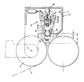
- a double carrier roller winding machine has two rotatably driven carrier rollers 1 and 2, between which a web 3 runs in from below.
- an ejection device 5 and an insertion device 6 integrated therein are shown from a waiting position indicated by dash-dotted lines into the transfer position shown in the drawing for winding cores suitable for winding the material web.
- a finished winding roll lying on the support rollers 1, 2 can be delivered to a transfer table (not shown).
- the insertion device 6 has a collet 8, with the clamping jaws 9, 11 of which winding sleeves of different diameters can be placed from the waiting position into the transfer position.
- a winding sleeve with a smaller diameter is 12 and one with a diameter larger winding tube is designated 13.
- the winding sleeves 12, 13 have a glue track 14 at a certain point, namely on their underside. With the aid of this, the beginning of a web 3 can be glued in a manner described in more detail below.
- a holding device 15 is arranged centrally to the clamping jaws 9, 11 of the collet 8, which essentially consists of a bar 16 which can be displaced in the vertical direction in the guides (not shown) and suction cups 17 attached to it at intervals and telescopic cylinders 18 which act as an adjusting element.
- the suction cups 17 are connected to a vacuum source, not shown.
- the double carrier roll winding machine works as follows:
- a finished winding roll lying on the support rollers 1, 2 is discharged onto a transfer table (not shown) with the aid of the ejection bar 7 of the ejection device 5.
- the ejection device 7 is moved from the waiting position into the transfer position shown. Since the insertion device 6 is coupled to the ejection device 5, a winding sleeve 12 or 13 entered in the waiting position is taken along with the movement in a precisely defined position by the collet 8 and brought into the transfer position shown. In the transfer position, the glue track 14 points downwards.
- the clamping jaws 9, 11 of the collet 8 are moved outwards.
- the holding device 15 takes effect.
- the suction cups 17 are lowered onto the winding tube 12 or 13, so that the winding tube 12 or 13 is held non-rotatably by the then effective suction air.
- the suction cups 17 or the strip 16 are then lowered by the telescopic cylinder 18 to such an extent that the winding tube 12 or 13 is brought into its winding position lying in the roller bed.
- the trace of glue 14 lies further exactly in the desired position.
Landscapes
- Replacement Of Web Rolls (AREA)
- Winding Of Webs (AREA)
- Saccharide Compounds (AREA)
- Medicines Containing Material From Animals Or Micro-Organisms (AREA)
Abstract
Description
- Die Erfindung bezieht sich auf ein Verfahren zum automatischen Einbringen einer zur Aufnahme einer Warenbahn geeigneten Wickelhülse in Doppeltragwalzen-Wickelmasc hinen, wobei die Warenbahn durchtrennt und der dabei entstehende Warenbahnanfang nach Ausstoß einer fertigen Wickelrolle an der mit einem Klebemittel versehenen Wickelhülse befestigt wird, die zunächst in definierter Lage von einer Wartestellung in eine oberhalb des von den Tragwalzen gebildeten Walzenbetts liegende Übergabestellung gebracht und danach bis zur Auflage auf den Tragwalzen in einer Anwickelstellung abgegeben wird.
- Bei einem aus der DE-PS 29 20 707 bekanntgewordenen Verfahren zum automatischen Trennen und Anwickeln einer Materialbahn wird die mit Klebemittel versehene Wickelhülse mit Hilfe einer Spannzange von der Wartestellung aus in die oberhalb des Walzenbetts liegende Übergabestellung plaziert. Auf diese Weise kann die Wickelhülse in genau definierter Lage, zum Beispiel mit nach unten weisender Leimspur oder einem Klebestreifen in die Übergabestellung gebracht werden. Zum Einbringen der Wickelhülse in die im Walzenbett befindliche Anwickelstellung wird die Spannzange einfach geöffnet, so daß die Wickelhülse im freien Fall in das Walzenbett gelangt. Dabei soll die Leimspur bzw. der Klebestreifen so zwischen die Tragwalzen fallen, daß die Leimspur oder der Klebestreifen die Tragwalzen nicht berührt bzw. beim neuen Wickeln die Leimspur zuerst die an der als Saugwalze ausgebildeten Tragwalze haftende Materialbahn anklebt und mit nimmt.
- Bei der Verarbeitung von Wickelhülsen mit großen Außendurchmesser-Unterschieden muß die Spannzange zwangsläufig höher angeordnet werden, d.h. die Übergabestellung besitzt einen größeren Abstand von der im Walzenbett befindlichen Anwickelstellung. Das hat zur Folge, daß die Fallhöhe bei der Verarbeitung von kleinen Wickelhülsen sehr groß wird. Dies führt wiederum dazu, daß sich die kleinen Wickelhülsen während des Fallens verdrehen und ihre Lage durch den Aufprall auf die Tragwalzen nochmals verändern. Hierdurch kommt es zu unerwünschten Störungen beim Anwickeln sowie zu einer Verschmutzung der Tragwalzen und einer gegebenenfalls vorhandenen Druckwalze durch das auf die Wickelhülse aufgetragene Klebemittel.
- Der Erfindung liegt nun die Aufgabe zugrunde, ein Verfahren vorzuschlagen, bei dem die vorgenannten Störungen vermieden werden, das sich vielmehr durch ein exaktes Einbringen der Wickelhülsen von der Wartestellung bis in die Übergabe- und Anwickelstellung in genau definierter Lage auszeichnet. Eine weitere Aufgabe besteht in der Schaffung einer Doppeltragwalzen-Wickelmaschine mit einer ein exaktes Einlegen der Wickelhülsen geeigneten Einlegeeinrichtung.
- Die verfahrensmäßige Aufgabe wird dadurch gelöst, daß die Wickelhülse während ihrer Bewegung von der Übergabestellung in die Anwickelstellung unverdrehbar gehalten wird. Auf diese Weise wird sichergestellt, daß sich die Wickelhülse nicht mehr in unkontrollierter Weise verdrehen kann, sondern in genau der gleichen Lage, wie sie von der Wartestellung in die Übergabestellung gelangt ist, bis in die Anwickelstellung abgegeben wird. Dadurch wird eine Verschmutzung der Tragwalzen vermieden und ein einwandfreies Anwickeln des Anfangs der Warenbahn gewährleistet.
- Das erfindungsgemäße Verfahren eignet sich insbesondere dann, wenn es sich um die Verarbeitung von mehreren nebeneinanderliegenden Wickelhülsen bzw. Hülsenstücken handelt, d.h. in solchen Fällen, wo andere Mittel, wie z.B. an den Hülsenenden angreifende Haken od.dgl. nicht verwendet werden können.
- In zweckmäßiger Weise ist vorgesehen, daß die unverdrehbare Halterung der Wickelhülse durch Unterdruck bereits beginnt, während sie in der Übergabestellung noch in definierter Lage, z.B. durch eine Spanneinrichtung gehalten wird. Hierdurch ist in jedem Fall sichergestellt, daß die einmal eingenommene Lage der Wickelhülse von der Wartestellung aus bis in die Anwickelstellung genau eingehalten wird.
- Das erfindungsgemäße Verfahren läßt sich auf einer Doppeltragwalzen-Wickelmaschine mit einer Einrichtung zum automatischen Einbringen einer mit einem Klebemittel, wie Klebestreifen, Leimspur od.dgl., längs einer Mantellinie zum Ankleben des Anfangs der Warenbahn versehenen Wickelhülse aus einer Wartestellung in eine oberhalb des von den Tragwalzen gebildeten Walzenbetts liegende Übergabestellung und eine im Walzenbett liegende Anwickelstellung und mit einer Einrichtung zum Ausstoßen einer fertigen Wickelrolle durchführen, bei der erfindungsgemäß die Einrichtung zum Einlegen der Wickelhülse eine zumindest im Bereich zwischen der Übergabestellung und der Anwickelstellung wirksame Haltevorrichtung aufweist. Mittels der Haltevorrichtung lassen sich im Außendurchmesser unterschiedliche Wickelhülsen in genau definierter Lage von der Übergabestellung in die Anwickelstellung bringen. Ein unkontrolliertes Verdrehen der Wickelhülsen mit einer Beeinträchtigung des Anwickelvorgangs ist damit ausgeschlossen.
- In zweckmäßiger Ausgestaltung der Erfindung ist die Haltevorrichtung von einer Saugvorrichtung gebildet, die aus einer Leiste mit daran mit Abstand befestigten Saugnäpfen besteht, die an eine Unterdruckquelle angeschlossen sind. In der Übergabestellung können die Saugnäpfe bis auf die Wickelhülse abgesenkt werden, dabei durch Unterdruck die Wickelhülse gehalten und dann die gesamte Haltevorrichtung bis in die Anwickelstellung der Wickelhülse abgesenkt werden. Zu diesen Zweck hat es sich als vorteilhaft erwiesen, wenn die Leiste in Führungen verschiebbar gelagert und durch ein Verstellelement beaufschlagbar ist. Das Verstellelement kann dabei von Teleskopzylindern gebildet sein.
- Von besonderer Bedeutung ist, daß die Teleskopzylinder an einem um die Achse der einen Tragwalze von einer der Wartestellung der Wickelhülse bis in deren Übergabestellung entsprechenden Stellung verschwenkbaren Ausstoßbalken der Ausstoßeinrichtung befestigt sind. Hierdurch ergibt sich eine sehr gedrängte Bauweise.
- Dazu trägt auch bei, wenn der Ausstoßbalken zugleich als Träger einer die Wickelhülse zwischen der Wartestellung und der Übergabestellung in definierter Lage haltenden Spannzange ausgebildet ist, zu deren Spannbacken die Teleskopzylinder zentrisch angeordnet sind.
- Ein bevorzugtes Ausführungsbeispiel der Erfindung ist in der Zeichnung schematisch dargestellt.
- Eine im einzelnen nicht dargestellte Doppeltragwalzen-Wickelmaschine besitzt zwei drehbar angetriebene Tragwalzen 1 und 2, zwischen denen von unten her eine Warenbahn 3 einläuft. Um die Drehachse 4 der Tragwalze 2 sind eine Ausstoßeinrichtung 5 und eine darin integrierte Einlegevorrichtung 6 aus einer mit strichpunktierten Linien angedeuteten Wartestellung in die in der Zeichnung dargestellte Übergabestellung für zum Aufwickeln der Warenbahn geeignete Wickelhülsen gezeigt. Mit Hilfe eines Ausstoßbalkens 7 der Ausstoßeinrichtung 5 kann eine auf den Tragwalzen 1,2 liegende fertige Wickelrolle an eine nicht dargestellten Übergabetisch abgegeben werden.
- Die Einlegeeinrichtung 6 besitzt eine Spannzange 8, mit deren Spannbacken 9,11 Wickelhülsen unterschiedlichen Durchmessers von der Wartestellung in die Übergabestellung plaziert werden können. Eine im Durchmesser kleinere Wickelhülse ist mit 12 und eine im Durchmesser größere Wickelhülse ist mit 13 bezeichnet. Die Wickelhülsen 12,13 besitzen an einer bestimmten Stelle, nämlich an ihrer Unterseite, eine Leimspur 14. Mit deren Hilfe kann in weiter unten näher beschriebener Weise der Anfang einer Warenbahn 3 angeklebt werden.
- Zentrisch zu den Spannbacken 9,11 der Spannzange 8 ist eine Haltevorrichtung 15 angeordnet, die im wesentlichen aus einer in nicht dargestellten Führungen in vertikaler Richtung verschiebbaren Leiste 16 sowie daran mit Abständen befestigten Saugnäpfen 17 und aus als Verstellelement wirkenden Teleskopzylindern 18 besteht. Die Saugnäpfe 17 sind an eine nicht dargestellte Unterdruckquelle angeschlossen.
- Die Doppeltragwalzen-Wickelmaschine arbeitet wie folgt:
- Eine auf den Tragwalzen 1,2 liegende fertige Wickelrolle wird mit Hilfe d es Ausstoßbalkens 7 der Ausstoßeinrichtung 5 auf einen nicht dargestellten Übergabetisch abgegeben. Zu diesem Zweck wird die Ausstoßeinrichtung 7 von der Wartestellung in die dargestellte Übergabestellung bewegt. Da die Einlegevorrichtung 6 mit der Ausstoßeinrichtung 5 gekoppelt ist, wird zugleich mit dieser Bewegung ein in der Wartestellung eingegebene Wickelhülse 12 bzw. 13 durch die Spannzange 8 in genau definierter Lage mitgenommen und in die dargestellte Übergabestellung gebracht. In der Übergabestellung weist die Leimspur 14 nach unten. Zur Abgabe der Wickelhülse 12 bzw. 13 in die mit strichpunktierten Linien dargestellte Anwickelstellung im Walzenbett der Tragwalzen 1,2 werden die Spannbacken 9,11 der Spannzange 8 nach außen bewegt. Kurz vor dem Öffnen der Spannzange 8 wird jedoch die Haltevorrichtung 15 wirksam. Zu diesem Zweck werden die Saugnäpfe 17 auf die Wickelhülse 12 bzw. 13 abgesenkt, so daß durch die dann wirksame Saugluft die Wickelhülse 12 bzw. 13 unverdrehbar gehalten wird. Gleichzeitig werden dann durch die Teleskopzylinder 18 die Saugnäpfe 17 bzw. die Leiste 16 soweit abgesenkt, daß die Wickelhülse 12 bzw. 13 in ihre im Walzenbett liegende Anwickelstellung gebracht wird. Dabei liegt die Leimspur 14 weiter hin genau in der gewünschten Stellung. Somit kann die durch eine nicht dargestellte Schneideinrichtung abgeschnittene Warenbahn 3 in exakter Weise an die Wickelhülse 12 bzw. 13 angeklebt werden. In der Zeichnung ist mit a die Senkhöhe einer im Durchmesser großen Wickelhülse 13 und mit b die Senkhöhe einer im Durchmesser kleinen Wickelhülse 12 dargestellt. Die Saugnäpfe 17 sind in der Anwickelstellung mit dünnen Linien angedeutet.
Claims (10)
Priority Applications (1)
| Application Number | Priority Date | Filing Date | Title |
|---|---|---|---|
| AT86103136T ATE39673T1 (de) | 1985-07-31 | 1986-03-08 | Verfahren und doppeltragwalzen -wickelmaschine zum automatischen einbringen einer zur aufnahme einer warenbahn geeigneten wickelhuelse. |
Applications Claiming Priority (2)
| Application Number | Priority Date | Filing Date | Title |
|---|---|---|---|
| DE19853527377 DE3527377A1 (de) | 1985-07-31 | 1985-07-31 | Verfahren und doppeltragwalzen-wickelmaschine zum automatischen einbringen einer zur aufnahme einer warenbahn geeigneten wickelhuelse |
| DE3527377 | 1985-07-31 |
Publications (3)
| Publication Number | Publication Date |
|---|---|
| EP0211136A2 true EP0211136A2 (de) | 1987-02-25 |
| EP0211136A3 EP0211136A3 (en) | 1988-03-30 |
| EP0211136B1 EP0211136B1 (de) | 1989-01-04 |
Family
ID=6277241
Family Applications (1)
| Application Number | Title | Priority Date | Filing Date |
|---|---|---|---|
| EP86103136A Expired EP0211136B1 (de) | 1985-07-31 | 1986-03-08 | Verfahren und Doppeltragwalzen -Wickelmaschine zum automatischen Einbringen einer zur Aufnahme einer Warenbahn geeigneten Wickelhülse |
Country Status (8)
| Country | Link |
|---|---|
| US (1) | US4726533A (de) |
| EP (1) | EP0211136B1 (de) |
| JP (1) | JPH06610B2 (de) |
| AT (1) | ATE39673T1 (de) |
| CA (1) | CA1275995C (de) |
| DE (1) | DE3527377A1 (de) |
| ES (1) | ES2000801A6 (de) |
| FI (1) | FI80660C (de) |
Families Citing this family (8)
| Publication number | Priority date | Publication date | Assignee | Title |
|---|---|---|---|---|
| DE3737503A1 (de) * | 1987-11-05 | 1989-05-24 | Beloit Corp | Rollenschneidemaschine |
| DE3811871A1 (de) * | 1988-04-09 | 1989-10-26 | Jagenberg Ag | Verfahren und vorrichtung zum aufwickeln von materialbahnen, insbesondere von papier- oder kartonbahnen |
| DE4029914A1 (de) * | 1990-09-21 | 1992-03-26 | Jagenberg Ag | Tragwalzen-wickelmaschine |
| DE19508207C2 (de) * | 1995-03-08 | 1998-05-14 | Kampf Gmbh & Co Maschf | Rollenschneid- und Wickelmaschine |
| AU3258697A (en) * | 1996-06-13 | 1998-01-07 | Beloit Technologies, Inc. | Core-insertion device for a winding machine |
| DE29613556U1 (de) * | 1996-08-05 | 1997-12-11 | Beloit Technologies, Inc., Wilmington, Del. | Hülseneinlegevorrichtung für Wickelmaschinen |
| US12264026B2 (en) * | 2020-12-28 | 2025-04-01 | Papeltec Overseas, Inc. | Method and apparatus for separating and spooling a paper web |
| CN112897135B (zh) * | 2021-02-23 | 2022-09-30 | 重庆富美包装印务有限公司 | 传送辊角度调节结构 |
Family Cites Families (12)
| Publication number | Priority date | Publication date | Assignee | Title |
|---|---|---|---|---|
| DE2743616A1 (de) * | 1977-09-28 | 1979-03-29 | Jagenberg Werke Ag | Vorrichtung zum aufwickeln bahnenfoermigen materials |
| NO790519L (no) * | 1978-06-21 | 1979-12-27 | Ahlstroem Oy | Spiralviklet hylse, fremgangsmaate for fremstilling av hylsen, fremgangsmaate for anvendelse av hylsen i et vikleapparat og anordning for bruk av hylsen |
| JPS557160A (en) * | 1978-06-30 | 1980-01-18 | Mitsubishi Heavy Ind Ltd | Strip coiling device |
| DE2909736C3 (de) * | 1979-03-13 | 1982-02-18 | J.M. Voith Gmbh, 7920 Heidenheim | Verfahren und Doppeltragwalzenroller zum Aufrollen von endlos zugeführten Bahnen |
| DE2920707C2 (de) * | 1979-05-22 | 1990-05-31 | Jagenberg-Werke AG, 4000 Düsseldorf | Verfahren und Doppeltragwalzen-Wickelmaschine zum automatischen Trennen und Anwickeln einer Warenbahn |
| AT373220B (de) * | 1979-07-27 | 1983-12-27 | Voith Gmbh J M | Doppeltragwalzenroller zum aufwickeln von materialbahnen |
| DE2930474C2 (de) * | 1979-07-27 | 1981-08-13 | J.M. Voith Gmbh, 7920 Heidenheim | Doppeltragwalzentwickelmaschine |
| DE2948877C2 (de) * | 1979-12-05 | 1982-02-18 | Jagenberg-Werke AG, 4000 Düsseldorf | Doppeltragwalzen-Wickelmaschine |
| DE3244966C1 (de) * | 1982-12-04 | 1984-06-07 | Jagenberg AG, 4000 Düsseldorf | Verfahren und Trenneinrichtung zum Durchtrennen von bahnfoermigem Zellstoff beim Anwickeln auf Wickelhuelsen |
| JPS59124644A (ja) * | 1982-12-27 | 1984-07-18 | Ishikawajima Harima Heavy Ind Co Ltd | 抄紙機に於ける巻取方法及びその装置 |
| FI69819C (fi) * | 1983-05-03 | 1986-05-26 | Waertsilae Oy Ab | Anordning foer banrullning |
| FI69820C (fi) * | 1983-05-12 | 1986-05-26 | Waertsilae Oy Ab | Anordning foer rullning av materialbana |
-
1985
- 1985-07-31 DE DE19853527377 patent/DE3527377A1/de active Granted
-
1986
- 1986-03-08 EP EP86103136A patent/EP0211136B1/de not_active Expired
- 1986-03-08 AT AT86103136T patent/ATE39673T1/de not_active IP Right Cessation
- 1986-04-24 FI FI861731A patent/FI80660C/fi not_active IP Right Cessation
- 1986-06-03 US US06/870,003 patent/US4726533A/en not_active Expired - Fee Related
- 1986-06-09 CA CA000511128A patent/CA1275995C/en not_active Expired - Fee Related
- 1986-07-30 ES ES8600742A patent/ES2000801A6/es not_active Expired
- 1986-07-31 JP JP61179011A patent/JPH06610B2/ja not_active Expired - Lifetime
Also Published As
| Publication number | Publication date |
|---|---|
| FI861731A0 (fi) | 1986-04-24 |
| DE3527377A1 (de) | 1987-02-12 |
| FI861731A7 (fi) | 1987-02-01 |
| FI80660B (fi) | 1990-03-30 |
| EP0211136A3 (en) | 1988-03-30 |
| ATE39673T1 (de) | 1989-01-15 |
| CA1275995C (en) | 1990-11-06 |
| JPS6231647A (ja) | 1987-02-10 |
| JPH06610B2 (ja) | 1994-01-05 |
| DE3527377C2 (de) | 1988-07-07 |
| ES2000801A6 (es) | 1988-03-16 |
| FI80660C (fi) | 1990-07-10 |
| EP0211136B1 (de) | 1989-01-04 |
| US4726533A (en) | 1988-02-23 |
Similar Documents
| Publication | Publication Date | Title |
|---|---|---|
| DE3416721C2 (de) | Vorrichtung zum Wickeln einer Bahn | |
| DE3885895T2 (de) | System und verfahren zum schneiden und aufwinden eines papierbandes. | |
| DE3308271A1 (de) | Vorrichtung zum aufwickeln laengsgeteilter bahnen und verfahren beim wickelrollen/huelsenwechsel | |
| DE2948877A1 (de) | Vorrichtung zum lagegenauen einsetzen von wickelhuelsen in wickelmaschinen | |
| DE2930474C2 (de) | Doppeltragwalzentwickelmaschine | |
| DE69501317T2 (de) | Verfahren zum vorbereiten des bahnanfangs einer vorratsrolle in einem rollenwechsler, rollenwechsler und bahnaufnahmevorrichtung | |
| DE2128777A1 (de) | Werkzeugmaschine zur Bearbeitung von Stangenmatenal | |
| DE2917601A1 (de) | Vorrichtung zum aufwinden von optischen glasfasern o.dgl. | |
| DE2628608A1 (de) | Vorrichtung zum binden von gegenstaenden mittels eines bandes | |
| EP1452474B1 (de) | Verfahren und Vorrichtung zur maschinellen Herstellung von spulenlosen Kabelwickeln | |
| DE2238370A1 (de) | Einrichtung und verfahren zum richten eines metallbandes | |
| EP0211136B1 (de) | Verfahren und Doppeltragwalzen -Wickelmaschine zum automatischen Einbringen einer zur Aufnahme einer Warenbahn geeigneten Wickelhülse | |
| DE3040398C2 (de) | Verfahren zum Auswechseln eines fertigen Wickels gegen einen leeren Wickelkern in einer Doppeltragwalzenwickelmaschine sowie Vorrichtung zur Durchführung des Verfahrens | |
| DE3328516C1 (de) | Doppeltragwalzen-Wickelmaschine | |
| EP0000065A1 (de) | Verfahren und Vorrichtung zum Bündeln von Stangen, Rohren, Profilen und anderen länglichen Gegenständen | |
| AT394508B (de) | Anlage zum herstellen von umreiften drahtgitterrollen | |
| DE3836498A1 (de) | Verfahren und vorrichtung zum entfernen eines um eine platte fuer gedruckte schaltungen gewickelten klebebandes | |
| CH679488A5 (de) | ||
| EP0406581B1 (de) | Vorrichtung zum Durchtrennen einer Bahn an einem Wendewickler | |
| EP0337079B1 (de) | Verfahren und Vorrichtung zum Aufwickeln von Materialbahnen, insbesondere von Papier- oder Kartonbahnen | |
| DE10139563B4 (de) | Vorrichtung und Verfahren zur Vorbereitung einer Vorratspapierbahnrolle für den fliegenden Rollenwechsel | |
| DE102004000040A1 (de) | Vorrichtung und Verfahren zum Einlegen einer Wickelhülse | |
| DE3151267C1 (de) | Vorrichtung an Wickelmaschinen | |
| DE2836480B2 (de) | Vorrichtung zum Aufnehmen und Drehen eines Bandbundes | |
| EP0593410A1 (de) | Verfahren und Vorrichtung zum streifenweisen Verlegen von Bandmaterial |
Legal Events
| Date | Code | Title | Description |
|---|---|---|---|
| PUAI | Public reference made under article 153(3) epc to a published international application that has entered the european phase |
Free format text: ORIGINAL CODE: 0009012 |
|
| AK | Designated contracting states |
Kind code of ref document: A2 Designated state(s): AT FR IT SE |
|
| PUAL | Search report despatched |
Free format text: ORIGINAL CODE: 0009013 |
|
| AK | Designated contracting states |
Kind code of ref document: A3 Designated state(s): AT FR IT SE |
|
| 17P | Request for examination filed |
Effective date: 19880302 |
|
| RAP3 | Party data changed (applicant data changed or rights of an application transferred) |
Owner name: JAGENBERG AKTIENGESELLSCHAFT |
|
| 17Q | First examination report despatched |
Effective date: 19880621 |
|
| GRAA | (expected) grant |
Free format text: ORIGINAL CODE: 0009210 |
|
| AK | Designated contracting states |
Kind code of ref document: B1 Designated state(s): AT FR IT SE |
|
| REF | Corresponds to: |
Ref document number: 39673 Country of ref document: AT Date of ref document: 19890115 Kind code of ref document: T |
|
| ITF | It: translation for a ep patent filed | ||
| ET | Fr: translation filed | ||
| PLBE | No opposition filed within time limit |
Free format text: ORIGINAL CODE: 0009261 |
|
| STAA | Information on the status of an ep patent application or granted ep patent |
Free format text: STATUS: NO OPPOSITION FILED WITHIN TIME LIMIT |
|
| 26N | No opposition filed | ||
| PGFP | Annual fee paid to national office [announced via postgrant information from national office to epo] |
Ref country code: FR Payment date: 19930219 Year of fee payment: 8 |
|
| PGFP | Annual fee paid to national office [announced via postgrant information from national office to epo] |
Ref country code: SE Payment date: 19930222 Year of fee payment: 8 |
|
| ITTA | It: last paid annual fee | ||
| PG25 | Lapsed in a contracting state [announced via postgrant information from national office to epo] |
Ref country code: SE Free format text: LAPSE BECAUSE OF NON-PAYMENT OF DUE FEES Effective date: 19940309 |
|
| PG25 | Lapsed in a contracting state [announced via postgrant information from national office to epo] |
Ref country code: FR Effective date: 19941130 |
|
| REG | Reference to a national code |
Ref country code: FR Ref legal event code: ST |
|
| EUG | Se: european patent has lapsed |
Ref document number: 86103136.7 Effective date: 19941010 |
|
| PGFP | Annual fee paid to national office [announced via postgrant information from national office to epo] |
Ref country code: AT Payment date: 19950223 Year of fee payment: 10 |
|
| PG25 | Lapsed in a contracting state [announced via postgrant information from national office to epo] |
Ref country code: AT Effective date: 19960308 |
|
| PG25 | Lapsed in a contracting state [announced via postgrant information from national office to epo] |
Ref country code: IT Free format text: LAPSE BECAUSE OF NON-PAYMENT OF DUE FEES;WARNING: LAPSES OF ITALIAN PATENTS WITH EFFECTIVE DATE BEFORE 2007 MAY HAVE OCCURRED AT ANY TIME BEFORE 2007. THE CORRECT EFFECTIVE DATE MAY BE DIFFERENT FROM THE ONE RECORDED. Effective date: 20050308 |