EP0177797B1 - Fadenspeicher und -liefervorrichtung, insbesondere für Textilmaschinen - Google Patents
Fadenspeicher und -liefervorrichtung, insbesondere für Textilmaschinen Download PDFInfo
- Publication number
- EP0177797B1 EP0177797B1 EP85111578A EP85111578A EP0177797B1 EP 0177797 B1 EP0177797 B1 EP 0177797B1 EP 85111578 A EP85111578 A EP 85111578A EP 85111578 A EP85111578 A EP 85111578A EP 0177797 B1 EP0177797 B1 EP 0177797B1
- Authority
- EP
- European Patent Office
- Prior art keywords
- thread
- bent
- drum
- drum body
- zone
- Prior art date
- Legal status (The legal status is an assumption and is not a legal conclusion. Google has not performed a legal analysis and makes no representation as to the accuracy of the status listed.)
- Expired
Links
- 239000004753 textile Substances 0.000 title claims description 3
- 238000003860 storage Methods 0.000 claims description 144
- 239000000463 material Substances 0.000 claims description 22
- 229920003023 plastic Polymers 0.000 claims description 9
- 239000004033 plastic Substances 0.000 claims description 9
- 230000002093 peripheral effect Effects 0.000 claims description 6
- 239000011324 bead Substances 0.000 claims description 5
- 230000000717 retained effect Effects 0.000 claims 3
- 238000004804 winding Methods 0.000 description 18
- 208000010300 Genu Varum Diseases 0.000 description 5
- 238000009940 knitting Methods 0.000 description 5
- 238000010276 construction Methods 0.000 description 4
- 238000004519 manufacturing process Methods 0.000 description 3
- 230000007704 transition Effects 0.000 description 3
- 206010062061 Knee deformity Diseases 0.000 description 2
- 229910000639 Spring steel Inorganic materials 0.000 description 2
- 230000009471 action Effects 0.000 description 2
- 230000004323 axial length Effects 0.000 description 2
- 230000008901 benefit Effects 0.000 description 2
- 230000008878 coupling Effects 0.000 description 2
- 238000010168 coupling process Methods 0.000 description 2
- 238000005859 coupling reaction Methods 0.000 description 2
- 230000006735 deficit Effects 0.000 description 2
- 230000000694 effects Effects 0.000 description 2
- 230000005489 elastic deformation Effects 0.000 description 2
- 239000002184 metal Substances 0.000 description 2
- 230000003014 reinforcing effect Effects 0.000 description 2
- 239000012858 resilient material Substances 0.000 description 2
- 238000000926 separation method Methods 0.000 description 2
- 238000004381 surface treatment Methods 0.000 description 2
- 239000000725 suspension Substances 0.000 description 2
- 230000001154 acute effect Effects 0.000 description 1
- 230000006978 adaptation Effects 0.000 description 1
- 239000011248 coating agent Substances 0.000 description 1
- 238000000576 coating method Methods 0.000 description 1
- 230000007423 decrease Effects 0.000 description 1
- 230000001419 dependent effect Effects 0.000 description 1
- 230000008021 deposition Effects 0.000 description 1
- 238000006073 displacement reaction Methods 0.000 description 1
- 239000000835 fiber Substances 0.000 description 1
- 230000001771 impaired effect Effects 0.000 description 1
- 230000007257 malfunction Effects 0.000 description 1
- 238000000034 method Methods 0.000 description 1
- 238000012806 monitoring device Methods 0.000 description 1
- 238000012544 monitoring process Methods 0.000 description 1
- 230000008569 process Effects 0.000 description 1
- 230000001737 promoting effect Effects 0.000 description 1
- 230000001105 regulatory effect Effects 0.000 description 1
- 230000000284 resting effect Effects 0.000 description 1
- 230000000630 rising effect Effects 0.000 description 1
- 239000007787 solid Substances 0.000 description 1
- 230000007480 spreading Effects 0.000 description 1
- 238000003892 spreading Methods 0.000 description 1
- 230000006641 stabilisation Effects 0.000 description 1
- 238000011105 stabilization Methods 0.000 description 1
- 238000011144 upstream manufacturing Methods 0.000 description 1
- 238000003466 welding Methods 0.000 description 1
Images


Classifications
-
- D—TEXTILES; PAPER
- D04—BRAIDING; LACE-MAKING; KNITTING; TRIMMINGS; NON-WOVEN FABRICS
- D04B—KNITTING
- D04B15/00—Details of, or auxiliary devices incorporated in, weft knitting machines, restricted to machines of this kind
- D04B15/38—Devices for supplying, feeding, or guiding threads to needles
- D04B15/48—Thread-feeding devices
-
- B—PERFORMING OPERATIONS; TRANSPORTING
- B65—CONVEYING; PACKING; STORING; HANDLING THIN OR FILAMENTARY MATERIAL
- B65H—HANDLING THIN OR FILAMENTARY MATERIAL, e.g. SHEETS, WEBS, CABLES
- B65H2515/00—Physical entities not provided for in groups B65H2511/00 or B65H2513/00
- B65H2515/30—Forces; Stresses
- B65H2515/31—Tensile forces
Definitions
- the invention relates to a thread storage and delivery device, in particular for textile machines, with a rotatably mounted storage drum, which has a number of elongated thread support elements arranged at equal radial distances from the drum axis and evenly distributed in the circumferential direction, which extends essentially in the drum axis direction on at least one drum body are fixed at one end in an unadjustable manner and form a thread support for a plurality of turns of a storage reel in a thread support area, as well as with a fixed thread feed and removal elements assigned to a storage drum on the thread feed or removal side and with a drive device for achieving a rotary movement of the storage drum.
- Thread delivery devices are known (DE-C-2461 746), whose storage drum is designed in the form of a cylindrical rod cage, on the rods of which a thread coming from a supply spool can be wound tangentially to form the storage roll.
- the rods are at a radial distance from the hub part of the cylindrical drum body, which has an upper and a lower ring flange, in which the rods are held at the ends.
- the windings of the storage roll lie (theoretically) point-wise on the circular-cylindrical rigid bars.
- the gaps present between adjacent bars and the hub portion of the drum body effectively prevent the occurrence of a lint deposit which affects the function of the thread delivery device.
- such a storage drum designed as a solid rod cage is relatively heavy, i.e. it has a considerable inert mass. This is of less importance as long as the storage drum - as a rule, together with the storage drums of further thread delivery devices, for example a circular knitting machine - is driven by an endless belt, which in turn is coupled to a drive source.
- this belt drive cannot suddenly be stopped or started, so that a start-stop operation of the storage drum is only possible in such a way that one of the storage drum's own positive clutch is disengaged or engaged. Because of its inert mass, the storage drum cannot come to a standstill even when such a clutch is disengaged. This would be e.g. desirable for circular knitting machines working with striping apparatus and for a number of other purposes.
- the construction of such a thread delivery device is still relatively complex.
- thread support elements of the storage drums of these thread delivery devices are designed as straight rods, teeth or the like, separate feed devices are required in order to axially advance the continuously forming storage roll on the storage drum, so that the thread turns of the storage roll always remain in the predetermined thread support area.
- the feed elements are formed by spring-elastic wire pieces which are anchored on one side of the drum body and protrude radially outward at one end on a hub of the drum body and on the other hand engage in a groove-like cam track which engages a stationary ring surrounding the circumferential storage drum is formed at a distance.
- radially projecting dividing elements for the storage wrap are designed more in the manner of wire brackets, each of which is attached at one end to a thread feed element, which can be moved axially up and down on two adjacent thread support elements in a cam-controlled manner.
- a thread storage and delivery device with eccentrically controlled rockers for axially feeding the storage roll is known from DE-A-2 436 936.
- a thread storage and delivery device belongs to the state of the art, but which works with a fixed storage drum, from which the thread can be pulled off overhead and the thread runs in the area of a conical widening, crossing are arranged to the throat of the conical extension webs which protrude into slots in the region of the conical extension of the storage drum body and are aligned with the corners of a polygon.
- each of the substantially L-shaped webs which extend approximately over the axial length of the storage drum body and are longitudinally adjustable in the axial direction, forms its own angular fillet at its end facing the angular fillet, the area of which can be moved into the slot by the longitudinal displacement is to achieve an adaptation to different threads or yarn 3 .
- the webs are not at least axially fixed on the storage drum body at one end spans, but adjustable and pivoted by means of a special bearing arrangement.
- the object of the invention is to provide a thread delivery device, the storage drum is characterized by a particularly simple, reliable construction and characterized in that the inert mass of the storage drum can be reduced to a minimum value, which, for example when driving by means of a stepper motor with low motor power, an exact Start-stop operation enables an automatic feed of the windings of the storage coil is guaranteed.
- the thread storage and delivery device mentioned at the outset is characterized according to the invention in that the thread support elements are formed by essentially L-shaped or U-shaped narrow, low-mass brackets which are guided or fastened on the other side to the drum body or a part connected thereto, and that each strap on the thread feed side is assigned a region that tapers radially inwards towards the thread outlet side, to which a thread support area is connected on the strap, and that the tapered and the substantially straight regions of all clips are each on an imaginary, towards the drum axis coaxial circular cylinder or cone.
- brackets can be manufactured in practically any appropriate shape without great manufacturing effort, so that, together with a light drum body, preferably made of plastic material, a very simple construction of the storage drum with a small inert mass can be achieved.
- the stirrups which are spaced apart in the circumferential direction, ensure a perfect slip-free coupling between the thread turns of the storage roll and the storage drum, while, on the other hand, impairment by lint deposition or the like. is largely excluded.
- brackets which are preferably arranged at least with their thread support areas at a radial distance from the drum body, are guided in a preferred embodiment in a resilient manner at least in places and at the other end with limited radial movement with respect to the drum body.
- thread support elements designed as spring-elastic sheet metal lamellae in a limited radial manner with respect to the drum body.
- the essentially L-shaped or U-shaped stirrups each have, in addition to the outwardly concavely curved or straight thread support region, an optionally elastic first stirrup leg with which they are fastened to the drum body.
- This first stirrup leg can still be guided laterally in the vicinity of the fastening point on the drum body, in order to prevent lateral deflection of the stirrups under the effect of the thread running up on the thread feed side, in particular if the latter is under a higher tension.
- the first stirrup legs can be embedded in the material of the drum body or inserted in some other way. It has proven to be advantageous if, for each bracket, the first bracket leg is inserted into the drum body with a bent fastening part and is held by latching means.
- stirrups on the side of the thread support area opposite the first stirrup leg have a substantially radial with respect to the Have drum body extending second bracket leg, which is designed as a guide element with corresponding guide means of the drum body or a part connected to it.
- the stirrups can be guided laterally and / or radially with their second stirrup legs, which can advantageously be done in such a way that the drum body has slots in which the second stirrup legs are guided.
- Such slots can advantageously be arranged at least in the region of an end wall of the essentially cup-shaped circular cylindrical drum body.
- stirrups with their second stirrup legs can be supported in the drum axis direction under pretension on a support surface arranged in the region of the bottom of the drum body.
- the stirrups are supported radially outwards with respect to the drum body on the side of the thread support area facing away from the first stirrup legs. This ensures that the stirrups with their thread support areas can be elastically pressed slightly inwards by the thread turns applied, in order to adapt themselves automatically to the tension conditions of the thread turns. On the other hand, however, this prevents the brackets from spreading radially outwards under the action of centrifugal force when the thread turns are applied with only very low tension and thus impair the storage winding.
- the brackets can advantageously be elastically biased radially outward against their support, so that they oppose their evasive movement to be carried out radially inward against a defined predetermined resistance.
- the drum body can have or carry a disk-shaped or star-shaped support part for the brackets, on which support or optionally guide surfaces for the brackets are formed.
- This circular disk-shaped support part can also be bead-like on its outer peripheral surface be designed in order to enable a perfect overhead take-off of the thread if this is necessary for the respective intended use of the thread delivery or storage device. Since the support part is generally made of relatively soft plastic material, it is advantageous if the support part carries on its outer peripheral surface a thread drain ring made of wear-resistant material, for example spring steel, which reliably prevents the thread from being sawn in. In the case of a multi-part design of the support part, the thread outlet ring can simultaneously hold the thread support part together.
- the arrangement can also be such that the brackets have bent holding parts on their second bracket legs, with which they can be supported on the supporting part.
- the free ends of the second stirrup legs are advantageously covered by a cover element placed on or arranged on the drum body base, which prevents the loops of thread that may form on the thread removal side from becoming caught on the ends of the stirrup legs as the tension of the running thread decreases.
- the region tapering radially inwards on the thread feed side can be formed directly on each bracket.
- the arrangement can also be such that the tapering region on the thread feed side is formed on at least a part of the drum body or a part connected to it, which protrudes radially outward beyond the brackets.
- the tapered areas lie on an imaginary circular cone. These inwardly tapering areas produce an automatic feed of the thread windings of the storage roll that are constantly forming during operation on the thread feed side, without the need for separate feed devices.
- the axial feed of the storage reel can, e.g. if there is no thread removal from the storage drum, i.e. in the event of a malfunction, are occasionally hindered, with the result that additional thread windings build up on the thread feed side.
- At least one thread deflector can be assigned to the storage drum on the thread feed side, which reaches up to the imaginary circular cone, on which the tapered areas of the bracket lie. It has proven to be very effective if the thread deflector has an essentially convex deflection edge or surface arranged on the side of the storage drum.
- each bracket has at least two thread support areas separated from one another by a radially projecting bead-like separation area.
- Each bracket can also carry a radially outwardly widening area on the thread outlet side of the yarn support area, the widening areas of all brackets in turn lying on an imaginary rotating body.
- the thin-walled, preferably essentially pot-shaped drum body generally consists of plastic material. It can have slot-like openings in the areas between the brackets in order to further reduce the material expenditure and the inert mass of the storage drum. At the same time, these slot-like openings can also be used to ventilate the overlying turns of the storage roll radially outward, so that fluff or the like is blown off. For similar reasons, the brackets can also carry parts acting as fan blades.
- the stirrups are made of a thin spring wire material, i.e. they are designed in the form of hardened, rust-free shaped wires, which generally do not require any additional surface treatment or coating, although these measures can of course be provided in individual cases.
- the stirrups can also be hardened only in limited areas of their longitudinal extent, where an elastic bend or special surface properties are important.
- brackets which are designed as flat shaped parts, for example punched out, can be formed in the thread support area as fan blades.
- a storage drum in which the brackets lie in the radial planes containing the drum axis is equally suitable for clockwise and counter-clockwise rotation.
- the brackets it is also conceivable for the brackets to lie in planes which are tangent to a rotational body coaxial with the drum axis, for example a circular cylinder or a circular cone.
- the thread delivery and storage device described can in principle be used for all thread-consuming machines and purposes in which an even thread delivery is important.
- Your storage drum can be driven in the usual way with circular knitting machines by means of a corresponding pulley from an endless drive belt, but it is particularly suitable for individual drive by means of a small electric motor, since, as explained at the beginning, it can be carried out with an extremely small inertial mass. In this way it is possible to create a "self-sufficient" thread delivery and storage device which predetermines the thread under exactly adhered to supplies conditions without the need for external monitoring by means of own monitoring devices or the like.
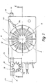
- the thread delivery and storage device shown in FIGS. 1, 2 has a holder 1 in the form of a rectangular, flat housing limited on the parallel side, which can be fastened, for example on a circular knitting machine, by means of fastening devices (not shown).
- a circular cylindrical recess 3 is formed on the outside, into which a storage drum 4 projects, which is arranged coaxially to the recess 3.
- the storage drum 4 has a substantially pot-shaped drum body 5, which is made of plastic material and which is placed by means of a hub 6 on the shaft 7 of an electric motor, in particular a stepping motor 8, which in turn projects through an opening 9 in the base wall 2 outwards via a fastening element 10 is rigidly connected to the holder 1.
- the drum body 5 carries a number at equal radial distances from the drum axis 11 and in the circumferential direction evenly distributed stirrups 12 which are bent from a thin spring wire with a smooth surface.
- the spring wire can have a circular cross section or a profile wire with, for example, an angular cross-sectional shape. It can have the same suspension properties over the entire length of the temple; However, embodiments are also conceivable in which each bracket 12 is only partially elastic by appropriate local hardening.
- Each of the resilient brackets 12 is bent substantially in a U-shape; it has a substantially straight thread support area 13 parallel to the drum axis 11 and then adjoining it on the thread feed side, i.e. 2 at the top, a radially inwardly tapering region 14 which merges via an arc 15 into a first stirrup leg 16 which runs essentially radially with respect to the drum axis 11 and is at least approximately horizontal.
- each stirrup On the side of the thread support area 13 opposite the first stirrup leg 16, each stirrup also bears a second stirrup leg 17 which also extends essentially radially to the drum axis 11.
- the first and the second stirrup legs 16 and 17 of all stirrups 12 lie on common circular cones imaginary to the drum axis 11, while the thread support areas 13 of the stirrups 12 are located on an imaginary, likewise coaxial circular cylinder.
- the stirrups 12 Adjoining their first stirrup legs 16, the stirrups 12 each carry fastening parts 180 which are angled at right angles and with which they are embedded in the casing 19 of the pot-shaped drum body 5 which is correspondingly widened in this area, so that at the same time lateral guidance of the first stirrup legs 16 is ensured in the vicinity of the fastening point is.
- stirrups 12 lie in slots 18 which extend radially to the drum axis 11 and which are formed in the bottom 20 of the drum body 5 and whose width is somewhat larger than the width of the stirrups 12.
- the bracket 12 are thus in the slots 18 on its second bracket leg 17 laterally ge leads; they are also supported with their second stirrup legs 17 under axial pretension on a support surface 21 formed on the bottom wall 20 of the drum body 5.
- each of the brackets 12 is rigidly attached to the drum body 5 in the area of its first bracket leg 16, ie on the thread feed side, while at its other end, ie in the area of the second bracket leg 17, it is guided in a radially limited manner on the drum body 5, while the walls of the slots 18 cause lateral guidance of the brackets 12 in this last-mentioned area.
- the drum body 5 is formed in the region of its bottom wall 20 with an approximately frustoconical cover part 22, into which the slots 18 extend and which prevents thread from getting caught on the ends of the second stirrup legs 17.
- a thread inlet eyelet 23 and a thread outlet eyelet 24 are each fixedly arranged on the holder 1 laterally next to the storage drum 4.
- the holder 1 carries a thread brake 25 to be explained in detail below and a thread inlet eye 26 arranged upstream thereof.
- the thread 27 drawn off from a supply spool (not shown) runs through the inlet eye 26 via the thread brake 25 and the inlet eye 23 tangentially onto the inwardly tapering regions 14 of the brackets 12 of the storage drum 4 driven by the electric motor 8.
- the resulting thread turns are pushed axially downward due to the inclination of the bow areas 14, with reference to FIG. 2, onto the essentially straight thread support area 13, where they form a storage roll, indicated at 28, consisting of several thread turns.
- the thread 27 is then withdrawn from the storage roll 28 and fed to a thread consumer (not shown) via the outlet eyelet 24.
- stirrups 12 Under the effect of the tension exerted by the thread windings of the storage winder 28, the stirrups 12 can pivot elastically somewhat inward about their arc pieces 15, the somewhat oblique, pretensioned second stirrup legs 17 sliding somewhat inwards on the support surface 21.
- the straight thread support areas 13 of the stirrups 12 are slightly inclined so that they come to lie on a common conical jacket which is coaxial with the drum axis 11 and which favors the axial advance of the storage roll 28.
- the elastic resistance which the brackets 12 oppose to this inward pivoting movement of their thread support area 13 depends not only on the elastic properties of the brackets 12 in the area of their “articulation point” for the respective bow 15, but also on the pretension with which the second bow legs 17 are supported on the support surface 21. By appropriate dimensioning of these sizes, if necessary, special properties of the thread material to be wound can be taken into account. Cases are also conceivable in which the brackets 12 are rigidly connected to the drum body 5, so that they are not capable of an elastic evasive movement.
- slit-like openings 29 are formed, each lying between adjacent brackets 12, which on the one hand further reduce the already small mass of the storage drum 4 by saving material and on the other hand with the rotating storage drum 4 as Fans act, through which the electric motor 8 is cooled and the thread windings of the storage roll 28 are ventilated radially outwards and blown off.
- the U-shaped wire brackets 12 are inserted with their fastening parts 180 into corresponding axially parallel bores of the drum shell 19.
- Your first stirrup legs 16 are laterally guided in approximately radially extending groove-like depressions 30 of the end face of the drum body shell 19.
- a stationary ring is used for the stationary locking, which is pushed into the drum body 5 with a flange 32 and is locked against the drum body jacket 19 at 33 by means of a circumferential bead and an associated depression.
- stirrups 12 protrude into the slots 18, which cause the stirrups 12 to be guided laterally in the region of the bottom wall 20.
- the stirrups 12 are supported radially outwards with respect to the drum body 5.
- a coaxial support disk 34 made of plastic material is placed on the bottom wall 20 of the drum body 5, which supports an annular flange formed as a bead 35 on the outer circumferential surface, which has an essentially circular cylindrical support surface 36 on its inside, against which the brackets 12 Support at the lower end of their thread support area 13.
- the brackets 12 are preloaded too elastically radially outwards and therefore bear against the support surface 36 under pretension. By correspondingly dimensioning this pretension, the elastic resistance can again be determined, which the brackets oppose with the already explained slight inward pivoting of their thread support areas 13.
- a thread drain ring 37 made of spring steel is inserted, the surface of which can also be coated and which holds the support disk 34 together in the case of a multi-part design.
- the described storage drum 4 according to FIG. 3 is suitable for pulling off the thread overhead from the storage roll 28.
- the running thread runs over the thread drain ring 37, which is made of wear-resistant material and thus ensures a perfect thread run.
- the brackets 12 consist of essentially U-shaped flat sheet metal stampings, which, however, can also be made of plastic material, for example.
- the bracket part 38 with its outer narrow end face corresponding to the thread support area 13 is designed as a fan wing, on which on one side the narrow arm-like area 14, which tapers inward and has the narrow, arm-like first bracket leg 16 and on on the other side, the arm-like narrow second leg 17 connects.
- stirrup part 38 is essentially rigid, at least in the region of the arch at 15 or in the vicinity of the clamping point of the first stirrup leg 16 there is an elasticity which allows the stirrup 12 to be preloaded radially outward, so that it is more elastic Bias is applied to the support surface 36 of the support plate 34 and can be pivoted radially inward under the forces exerted by the thread windings of the storage roll 28 about a hinge point in the vicinity of the arch 15.
- the first bow legs 16) of the bow 12 are in this case in turn inserted into corresponding groove-like depressions 30 in the end wall of the drum shell 19. They are held captively by welding the plastic material in the region of the trough-shaped depressions 30.
- bracket parts 38 which act as fan blades, passes through openings 39 in the support disk 34, which at the same time forms the bottom wall of the drum body 5, into the drum body 5 and radially outwards between the brackets 12, the thread windings of the storage roll 28 being blown through. Since the drum body jacket 19 extends in this case, starting from the hub part 6, only in the area above the bracket parts 38, there are no parts preventing the passage of air between the bracket parts 38.
- the brackets 12 can be brought into any shape without increasing the manufacturing outlay.
- the straight thread support area 13 for each stirrup into two thread support areas 13a, 13b by a bulge-like protruding separation area 40 or for each stirrup 12 in the manner shown in FIG. 7 on the Thread outlet side adjoining the thread support area 13 to provide a radially outwardly widening area 41.
- the outwardly widening areas 41 of all the brackets 12 are in turn located on a common imaginary circular cone or another purpose-oriented rotating body. They prevent - if this is necessary in consideration of the processed thread or the employment relationships - that the lower turns of the storage roll 28 fall down from the storage drum 4.
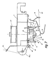
- the drum body 5 of the storage drum 4 illustrated in FIGS. 5, 6 is configured similarly to that in FIG. 4. Since the brackets 12 are bent from wire in this case, separate fan blades 42 are provided for ventilating the thread windings of the storage roll 28, which are formed in the annular space enclosed by the bracket portions 13 and formed approximately radially on the drum body shell 19 projecting from the hub part 6 in the manner of an annular flange are.
- a thread deflector 43 is arranged on the underside of the holder 1 next to the storage drum 4 in the embodiment according to FIGS. 5, 6, which in the manner shown in FIG. 6 in particular with a convex thread deflection edge 44 in the region of the protrudes from the imaginary circular cone described inwardly tapering bracket regions 14.
- the thread deflector 43 has an inclined surface 45, which runs from the thread deflection edge 44 approximately parallel to the bow regions 14, which runs at a short distance from the bow regions 14 and which intersects a gently curved deflection surface 46 along the thread deflection edge 44, so that the one shown in FIG. 6 apparent wedge-shaped cross-sectional shape results.
- the storage drum 4 is combined with a conventional plate thread brake 25a.
- a thread infeed and thread outfeed sensors are illustrated together with a loop deflector bar at 49, 50 and 51, respectively.
- the storage drum 4 corresponds in its basic structure to the embodiment according to FIGS. 1, 2.
- the brackets 12 are, in addition to the embodiment according to FIGS. 1, 2, additionally radial supported to the outside.
- the brackets 12 are each provided on their second bracket legs 17 with a hook-like bent holding part 52 which engages behind a corresponding circular-cylindrical holding surface 53 of a cover part 22a placed on the drum body base 20.
- the brackets 12 can lie in the radial planes containing the drum axis 11 or - if a storage drum drive is only possible in one direction of rotation - the arrangement can be such that the planes containing the brackets 12 are tangential to a circular cylinder coaxial with the drum axis 11 or cone run.
- the thread delivery device becomes an autonomous thread delivery device which is not only able to deliver thread continuously or in exact start-stop operation, but also during the thread delivery automatically maintain a predetermined tension for the supplied thread, and ensure that the thread coming from the supply spool is wound onto the storage drum with constant tension, so that the storage reel 28 is properly built and advanced.
- the electric thread brake 25 has a direct current motor 70 which is inserted into a corresponding bore of the holder 1 and which carries a second storage drum 4a, which is basically constructed similarly to the storage drum 4 already described with reference to several exemplary embodiments. It only has a smaller diameter. Its bracket 12 and its drum body 5 are only indicated schematically in FIGS. 1, 2.
- the thread 27 running in via the inlet eye 26 is looped around the second storage drum 4a in several turns, so that it is coupled with it without slippage.
- the associated electric motor 70 which acts as a brake motor, strives to drive the second storage drum 4a in the opposite direction of rotation as the storage drum 4; however, its torque is designed to be significantly weaker than the stepper motor 8, so that it is driven via the thread 27 against its direction of rotation when the stepper motor 8 is running. In doing so, it develops a braking torque which acts on the thread 27 via the second storage drum 4a and which ensures that the thread 27 always runs onto the storage drum 4 with a predetermined thread tension.
- the size of this braking torque of the electric motor 70 can be regulated by correspondingly influencing one of the electrical input parameters (current, voltage) of the electric motor.
- the circuit parts of the associated control circuit are designed in the form of printed circuits, the associated circuit boards 86, 87 of which are accommodated together with the housing 600 of a signal transmitter in the holder 1, the interior of which is closed by a cover 88 (see FIG. 2).
- the thread running out of the storage drum 4 is scanned by a spring-loaded sensor 55, which correspondingly rotates a shaft 56, which emits a thread tension signal via the rotary encoder 600, which is fed into the control circuit and controls the electric motor 8 to a constant thread tension.
- brackets 12 are each essentially U-shaped. Embodiments are also conceivable in which these brackets 12 are essentially L-shaped, i.e. the second stirrup legs 17 are omitted.
- the brackets can then, for example, only be guided laterally and radially in corresponding slots 860 (FIG. 6) of the support disk 34 or the bottom wall 20 of the drum body 5, as will be explained below.
- the stirrups 12 lie in the planes containing the drum axis 11. This means that the storage drums can be used equally well in both directions of rotation. In principle, however, an embodiment could also bring advantages for certain applications in which the brackets 12 are somewhat “oblique” with respect to the drum axis 11, that is to say in planes that intersect the drum axis 11 at a small acute angle. This Angle could be between 3 ° and 5 °, although other angle values are also conceivable. Similarly, the stirrups with their thread support area 13 could also be designed following a spiral. Such an inclined position of the stirrups 12 can, for example, prevent the storage roll 28 from falling downward.
- brackets 12 are also held on the drum body 5 essentially in the direction of the drum axis.
- brackets 12 consist of a resilient material, e.g. spring wire, and only on their first bracket legs 16, i.e. are rigidly attached on one side to the drum body 5, they have, as practical experience has shown, set in motion somewhat by the thread running in and out. This is due to the fact that the stirrups with their thread support areas 13 are arranged distributed around the circumference of the storage drum 4 or 4a, so that the thread does not lie precisely on a smooth cylindrical surface, but on the corner edges of a polygonal rotating body formed by the thread support areas 13. This dynamic behavior of the bracket 12 is suitable for significantly facilitating and favoring the axial advance of the storage roll 28.
- a resilient material e.g. spring wire
- the drum body 5 is placed on a two-part hub 6a, 6b, the lower hub part 6b of which has an integrally formed, radially outwardly projecting ring flange 60, while a cover-like ring disk 61 is placed on the upper hub part 6a .
- the ring flange 60 and the ring disk 61 overlap the second and first legs 17 and 16 of the U-shaped wire bracket 12 in the region of their fastening or guide points on the drum body 5 in the manner shown in FIG. 8.
- a radially inwardly tapering area 14 is in turn formed, which merges into the first bracket leg 16 via an arc 15.
- each bracket 12 is formed with a bulge-shaped curved bracket area 41, to which the second bow leg 17 adjoins.
- Both bracket legs 16, 17 each have an approximately angled fastening part 180 at the end, the arrangement being such that the two fastening parts 180 of a bracket 12 are aligned coaxially with one another.
- the two fastening parts 180 of a bracket 12 are each in the form of coaxial bores 181, 182 and mutually coaxial recesses of the drum body 5 are inserted and held therein by the overlapping ring flange 60 or the ring disk 61.
- the cylindrical recess 181 corresponds exactly to the diameter of the associated fastening part 180 so that it is held in a fixed position
- the other recess 182 is formed with a larger diameter, with the result that the lower fastening part 180 and thus also the second leg 17 of each bracket is guided radially and laterally movable.
- the brackets 12 are supported on their legs 16, 17 in the drum axis direction on support surfaces 62, 63 of the drum body 5; they are under such a prestress that their two legs 16, 17 rest on the bearing surfaces 62, 63 with spring force.
- a radial support 64 of small axial length is provided with respect to the drum body 5.
- the brackets 12 can easily be hooked into the recesses 181, 182 with their fastening part 180 during assembly.
- an endless thread deflection ring 65 or 66 which is coaxial with the drum axis and which can consist for example of a plastic material and whose task is to prevent threads between the individual wire stirrups 12 can get and get caught there, which could lead to thread breaks.
- the two deflection rings 65, 66 - or at least one of them - can also perform a support and stabilization function for the brackets 12 if this should be necessary in individual cases.
- the lower deflection ring 66 is formed in the region of the stirrups 12 with radial slots 67 which are open towards the outside and into which the individual stirrups 12 partially engage with their regions 41.
- the width of the slots 67 corresponds to the diameter of the bracket 12 made of cylindrical spring wire material; the depth of the slots 67 is approximately equal to half the wire thickness of a bracket 12, which means that the bracket 12 is embedded in such a slot 67 to approximately half its diameter.
- the upper deflection ring 65 can be designed in a corresponding manner; however, the arrangement can also be such that this deflection ring 65 is rigidly connected to the brackets 12, which are embedded in it, for example.
- brackets 12 made of elastic wire material with their lower fastening parts 180 are radially limitedly movable in the recesses 182 and this mobility is also not impaired by the length of the slots 67 in the lower deflection ring 66 - to prevent such impairment of the mobility is between the Ring flange 60 and the second stirrup legs 17 at 68 each have an air gap of a few tenths of a millimeter - the bends) 12 can taper conically with their straight thread support area 13, viewed from top to bottom, when they pass from the thread roll onto the thread Support area 13 exerted radial force is greater than the bias of the bracket.
- This taper is limited in that the lower fastening part 180 comes to rest on the inner edge of the recess 182. In such a deformed state, the straight thread support areas 13 of all brackets 12 lie on the surface of an imaginary circular cone, the tip of which lies on the thread outlet side on the drum axis.
- stirrups 12 are each supported radially at 64, the explained inward pivoting movement of the lower parts of the stirrups 12 remains essentially limited to their thread support areas 13 and the adjoining bead-like areas 41.
- the radial support points at 64 can lie not only on reinforcing ribs, as shown in FIG. 8, but also in each case on a fan blade integrally formed on the drum body 5, which is designated 69 in FIG. 8 and is delimited with respect to the drum body 5 by dashed lines.
- brackets 12 are designed without their own elastic prestress, while the lower deflection ring 66 consists of a flexible material and is firmly connected to the brackets 12. The elastic deformation of the deflection ring 66 thus produces a corresponding radial suspension of the brackets 12.
- stirrups 12 lie in their unloaded basic position with their thread support area 13 on a circular cone, the tip of which lies on the thread feed side on the drum axis.
- the winding diameter increases slightly from the thread inlet side to the thread outlet side.
- Such an arrangement can be advantageous, for example, if smooth and inelastic yarns are to be processed which naturally have little hold on the thread support areas 13 of the stirrups 12, so that the turns tend to fall off.
- a certain compensation takes place - within the elastic limits of the thread material.
- the arrangement can advantageously be made such that when the fastening part 180 is in contact with the radially inner wall of the recess 182, the thread support area 13 of each bracket 12 lies on a circular cylinder coaxial with the drum axis.
- the bead-like outwardly bent regions 41 of the stirrups 12 form, together with the lower deflecting ring 66, a thread rewinding board, as is present, for example, in the embodiment according to FIG. 3 in the form of the thread outlet ring 37 and also has the task of keeping loose thread turns from falling .
- This thread rewinding board simultaneously exerts a certain entraining function on the thread, as a result of which excess thread experiences a kind of forced entrainment without, however, being dragged along by force.
- the outside diameter of the bead-like rotating body described by the regions 41 of the brackets 12 should expediently be in a certain ratio to the outside diameter of the lower deflection ring 66.
- brackets 12 in the bead region 41 are embedded in the slots 67 of the deflection ring 66 up to about half the wire thickness. This also ensures that when the thread is pulled upside down from the storage drum by hand (for example, if there is excess thread on the storage drum), the thread can be easily removed without picking or tearing.
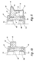
- the drum body 5 in the embodiment according to FIG. 8 is illustrated again in FIG. 10 without a bracket 12. It can be seen from this figure that lateral guide ribs 70 are assigned to the first bracket limbs 16 of the brackets 12 in the region of the upper bearing surface 62, which lead to the assigned recess 181 and result in lateral guidance of the bracket limbs 16. While the diameter of the upper cylindrical recess 181 corresponds approximately to the wire diameter of a bracket 12, the diameter of the associated lower cylindrical recess 182 is approximately 0.15 mm larger than the wire diameter.
- FIG. 11 corresponds fundamentally to that according to FIGS. 8 to 10, with the difference, however, that the stirrups 12 over the entire length of their first legs 16, their arches 15 and their inclined regions 14 on the part 69 of the rib, which may be divided into ribs Drum body 5 are supported.
- bracket 12 with their fasteners 180 on both sides in cylindrical recesses 181, 182 radially immovable ge holds, which means that the two cylindrical recesses 181, 182 of a bracket 12 each have the same diameter that corresponds to the wire diameter.
- the ring flange 60 lies directly on the second stirrup legs 17.
- the deflection ring 65 which is also present, is not shown.
- the drum body 5 In its region 69 shown in cross section in FIG. 11, the drum body 5 extends as a full body around the entire circumference, so that no thread can enter between adjacent brackets 12 in this region.
- FIG. 11 can also be seen together with that according to FIG. 8 in such a way that it illustrates a different sectional representation of an embodiment according to FIG. 8, in which a bracket 12 according to FIG. 8 alternately with its lower second leg 17 is guided in a radially limited manner and the next bracket 12 is rigidly supported on the drum body 5 at both ends according to FIG. 11.
- FIG. 12 is also similar to that according to FIGS. 8 to 11, but a simpler design of the bracket 12 is provided.
- Each bracket 12 is only substantially U-shaped in the section given by its first leg 16, the adjoining arch 15 and the inwardly inclined region 14.
- the angled fastening part 180 adjoining the first leg 16 is coaxial with the part forming the straight thread support region 13, which adjoins the region 14 and is held in a corresponding recess 182 of the lower ring flange 60.
- the diameter of the recess 182 can, as illustrated in FIG. 12; be equal to the diameter of the associated bracket 12 made of wire, with which the bracket 12 is rigidly supported at both ends.
- the arrangement can also be such that the recesses 182 either all or alternately every second, similarly as illustrated in FIG. 8, have a larger diameter than the wire diameter of the bracket 12. So that the spring-elastic bracket 12 are guided radially limited movement at their lower ends.
- brackets 12 each rest on an all-round bead-like part 69 of the drum body 5, which carries an open-edge groove 71 for each bracket 12, in which the associated bracket 12 is guided laterally.
- the radial mounting of the upper fastening parts 180 of the brackets 12 takes place between the above-mentioned bead-like part 69 and a cylindrical flange 72 formed on the annular disk 61, which overlaps the fastening parts 180 of the brackets 12 in the manner shown in FIG. 12.
- a toothing 730 is formed, in which a drive toothed belt, not shown, can engage.
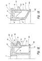
- FIG. 13 An embodiment with even simpler wire clips 12 is illustrated in FIG. 13.
- the wire brackets 12 are only bent in an L-shape, with their first leg 16 each resting on the support surface 62 of the drum body 5 running at right angles to the axis of rotation of the drum or, as shown, a molded part 73 connected to it. They are held by the attached washer 61, where necessary, lateral guide ribs for the first stirrup legs 16 can be provided either in the washer 61 or in the area of the support surface 62.
- brackets 12 penetrate the circumferential bead-like area 69 which, with its tapered surface 140, which may be designed to be wear-resistant, forms the area tapering radially inwards towards the thread outlet side - comparable to area 14 of FIG. 8 - of the storage drum.
- the conical surface 140 can also be interrupted by grooves, as it is also conceivable to subdivide the entire bead-like region 69 in radial planes by slots, so that it consists of individual, congruent, spaced-apart ribs.
- the brackets 12 are in turn held with their end-side fastening parts 180 in cylindrical recesses 182 of the drum body 5, the diameter of the recesses 182 being either equal to or larger than the wire diameter, as has already been explained in detail with reference to the other embodiments.
- brackets 12 are exposed with a section 74 which forms a rack gear toothing in which a drive toothed belt (not shown) can engage.
- the thread support area 13 is not straight, but is concavely curved toward the outside of the storage drum.
- the curvature of the stirrups 12 is uniform over the entire thread support area, which also includes the inwardly tapering area 14 of the embodiment according to FIG. 8.
- the advantage over known, fully machined storage drums, which are basically designed in the manner of an anchor cap, is that the stirrups 12 only have a point contact with the thread turns and the winding body thus forms a kind of “polygon”. This minimizes the risk of threads sticking to the storage drum. Since the stirrups 12 are bent in a simple manner from a hard, resilient material, a further wear-reducing surface treatment, as is required with a fully worked storage drum in the region of the thread inflow and outflow or the thread contact surface, is generally unnecessary .
- the brackets 12 are rigidly supported on the drum body 5 at both ends by their fastening parts 180; they are also supported radially approximately in the middle of the thread support area 13 on a molded on the drum body 5 support disk 75, which has on its outer circumference open-edge grooves 76, in which the bracket 12 are laterally guided.
- the upper washer 61 is widened like a cover so that it covers the first legs 16 of the brackets 12 over the entire length and even largely covers the arch 15 of each of the brackets 1Z.
- brackets 12 could, in the manner shown in FIG. 8, be guided in the region of their lower fastening parts 180 in radially limited fashion in recesses 182 of larger diameter.
- each bracket 12 engages in a corresponding recess 181 of the all-round bead-like part 69 of the drum body 5.
- the diameter of each recess 181 is larger than the diameter of the associated bracket 12 made of wire.
- the stirrups 12 on the thread inlet side are fundamentally held on their first stirrup legs 16 in a manner similar to the embodiment according to FIG. 13, so that a further discussion is unnecessary in this respect.
- the bead-like region 69 of the drum body 5 projects radially beyond the brackets 12 in the region of its obliquely inwardly inclined peripheral surface 140; it is provided with longitudinal slots 141, in which the brackets 12 are radially movable in their areas 14, but are guided laterally.
- the stirrups 12 are received in recesses 182 in the drum body 5, the diameter of which is larger than the diameter of the stirrups 12 made of wire.
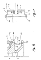
- FIG. 17 shows a particularly simple embodiment of a storage drum 4 which is distinguished by a very small, inert mass.
- the essentially U-shaped wire clips 12 are inserted with the fastening parts 180 of their second legs 17 directly into corresponding recesses 182 of the same diameter of the drum body 5 reduced to the hub 6.
- a thread-deflecting ring 66 consisting of wire and also serving as a support ring.
- the other thread deflection ring 65 is also designed as a wire ring and is fastened in the same way to the brackets 12 in the region of their second leg 17. If necessary, a bulging area 41 can also be provided on the brackets 12.
- FIGS. 18 to 20 illustrate an embodiment similar to that according to FIGS. 8 to 10, to the explanation of which reference is made.
- the stirrups 12 made of spring wire are not supported radially in the thread support area 13.
- the upper bearing surface 62 of its first legs 16 is designed with a smaller diameter, with the result that the spring action can extend over a larger area of the brackets 12.
- grooves 760 are provided on the inside of the upper annular disk 61, which is enlarged radially, similar to FIG. 14, into which the brackets 12 engage in the region of their arches 15 and the ends of their first legs 16.
- the annular disc 61 radially overlaps the bracket 12; its outboard 770, which partially overlaps the arches 15, at the same time acts as a thread deflector, thereby promoting the thread inlet.
- protection against fiber flying from above is achieved in this way.
- the lower ring flange 60 is also radially advanced to the straight thread support area 13 of the bracket 12. It has a shell-shaped outside and is provided on its inside with grooves 780, in which the brackets 12 are guided laterally, in such a way that the brackets 12 remain free to move radially. With each bracket 12, the thread support area is bent obliquely at the transition point to the second leg 17, as can be seen from FIG. 18.
- radially outwardly protruding cams 79 are formed, which extend in a garland shape between adjacent brackets 12. The bracket 12 are exposed with their thread support area about half the wire cross-section, as indicated at 80 in FIG. 19.
- the cams 79 can either extend in the manner of an outwardly convex circular arc between two adjacent brackets 12 or, as indicated at 81, can be formed between two adjacent brackets 12 by two convex radii with an intervening “notch”, embodiments also being conceivable where the cams are bounded by straight chords, as illustrated at 82.
- separate tooth-like or finger-like projections 83 can also be provided, which are arranged in the area between adjacent brackets 12.
- cams 79 In order to prevent thread loops from getting between the brackets 12 and the ring flange 60 in the area of the cams 79, it is expedient that the cams 79 in the direction shown in FIG whose transition to the second arm legs 17.
- each bracket 12 is inserted on the opposite side with its fastening part 180 into a corresponding recess 182 of the lower ring flange 60.
- stirrups 12 can also be designed as sleeves or turned parts, so that the two first stirrup legs 16 are formed by producing a molded cone.
Landscapes
- Engineering & Computer Science (AREA)
- Textile Engineering (AREA)
- Forwarding And Storing Of Filamentary Material (AREA)
- Storing, Repeated Paying-Out, And Re-Storing Of Elongated Articles (AREA)
- Knitting Machines (AREA)
Applications Claiming Priority (2)
| Application Number | Priority Date | Filing Date | Title |
|---|---|---|---|
| DE3437252 | 1984-10-11 | ||
| DE3437252A DE3437252C1 (de) | 1984-10-11 | 1984-10-11 | Fadenspeicher- und -liefervorrichtung,insbesndere fuer Textilmaschinen |
Publications (2)
| Publication Number | Publication Date |
|---|---|
| EP0177797A1 EP0177797A1 (de) | 1986-04-16 |
| EP0177797B1 true EP0177797B1 (de) | 1988-10-05 |
Family
ID=6247619
Family Applications (1)
| Application Number | Title | Priority Date | Filing Date |
|---|---|---|---|
| EP85111578A Expired EP0177797B1 (de) | 1984-10-11 | 1985-09-13 | Fadenspeicher und -liefervorrichtung, insbesondere für Textilmaschinen |
Country Status (11)
| Country | Link |
|---|---|
| US (1) | US4669677A (esLanguage) |
| EP (1) | EP0177797B1 (esLanguage) |
| JP (1) | JPS61106378A (esLanguage) |
| CN (1) | CN1006725B (esLanguage) |
| CZ (1) | CZ278749B6 (esLanguage) |
| DD (1) | DD239619A5 (esLanguage) |
| DE (2) | DE3437252C1 (esLanguage) |
| ES (1) | ES8700208A1 (esLanguage) |
| HK (1) | HK791A (esLanguage) |
| SG (1) | SG28089G (esLanguage) |
| SU (1) | SU1672928A3 (esLanguage) |
Families Citing this family (21)
| Publication number | Priority date | Publication date | Assignee | Title |
|---|---|---|---|---|
| DE3601586C1 (de) * | 1986-01-21 | 1987-05-27 | Memminger Gmbh | Fadenspeicher- und -liefervorrichtung,insbesondere fuer Textilmaschinen |
| DE3711558C1 (de) * | 1987-04-06 | 1988-06-23 | Sipra Patent Beteiligung | Fadenliefervorrichtung fuer Strickmaschinen |
| ES2009817B3 (es) * | 1987-04-11 | 1989-10-16 | Sobrevin Soc De Brevets Industriels-Etablissement | Dispositivo suministrador de hil |
| SE8900006D0 (sv) * | 1988-12-31 | 1988-12-31 | Iro Ab | Anordning vid en garnlager- och matningsenhet foer textilmaskiner foeretraedesvis vaevmaskiner |
| DE4206607A1 (de) * | 1991-09-26 | 1993-04-01 | Erich Roser | Fadenliefergeraet fuer fadenverbrauchende textilmaschinen |
| FR2733561B1 (fr) * | 1995-04-25 | 1997-06-06 | Alliedsignal Europ Services | Patin et piston de frein a accouplement automatique |
| DE19546404A1 (de) * | 1995-12-12 | 1997-06-19 | Terrot Strickmaschinen Gmbh | Fadenliefervorrichtung |
| JP4072647B2 (ja) * | 1996-01-23 | 2008-04-09 | ニッタ株式会社 | コード類の張力調整機構 |
| DE19811240C2 (de) * | 1998-03-14 | 2000-05-31 | Memminger Iro Gmbh | Fadenliefergerät mit verbessertem Fadenlauf |
| US6969217B1 (en) * | 2004-06-17 | 2005-11-29 | Basinger Jon E | Pipe puller |
| ITMI20080410A1 (it) | 2008-03-11 | 2009-09-12 | Btsr Int Spa | Dispositivo e metodo per l'alimentazione a tensione costante di filati alimentati in modo discontinuo |
| CN101307524B (zh) * | 2008-06-27 | 2010-10-20 | 李伟民 | 一种织布机用储纬器 |
| EP2218670B1 (en) * | 2009-02-16 | 2011-03-16 | L.G.L. Electronics S.p.A. | Yarn feeder with lightweight yarn-winding drum |
| JP5915219B2 (ja) * | 2012-02-07 | 2016-05-11 | 村田機械株式会社 | 糸巻取装置 |
| DE102012111784B3 (de) * | 2012-12-04 | 2014-03-27 | Memminger-Iro Gmbh | Fadenliefergerät |
| TWI623661B (zh) * | 2014-12-29 | 2018-05-11 | Po Lin Chen | Yarn feeding wheel |
| USD794715S1 (en) * | 2015-09-15 | 2017-08-15 | Btsr International S.P.A. | Yarn feeder |
| USD794683S1 (en) * | 2015-09-15 | 2017-08-15 | Btsr International S.P.A. | Yarn feeder |
| CN106435965A (zh) * | 2016-12-10 | 2017-02-22 | 无锡银联齿轮传动机械有限公司 | 储纬器用梭鼓 |
| CN107354570B (zh) * | 2017-09-14 | 2023-05-02 | 浙江叶晓针织机械有限公司 | 哈夫盘机构 |
| US11828009B2 (en) * | 2018-05-16 | 2023-11-28 | Fabdesigns, Inc. | System and method of unspooling a material into a textile machine |
Family Cites Families (18)
| Publication number | Priority date | Publication date | Assignee | Title |
|---|---|---|---|---|
| DE1785508B2 (de) * | 1965-11-11 | 1975-04-30 | Fouquet - Werk Frauz & Planck, 7407 Rottenburg | Selbstregelnde Fadenliefervorrichtung für jedes einzelne System einer mehrsystemigen Rundstrick- oder Rundwirkmaschine |
| SE304070B (esLanguage) * | 1967-03-22 | 1968-09-16 | K Rosen | |
| BE791857A (fr) * | 1971-11-29 | 1973-03-16 | Rosen Karl I J | Fournisseur de fil pour machines textiles |
| CH571601A5 (esLanguage) * | 1973-02-20 | 1976-01-15 | Skf Kugellagerfabriken Gmbh | |
| FR2239882A1 (en) * | 1973-07-31 | 1975-02-28 | Dreville Olivier | Knitting yarn feed control system - has photo-electric monitoring of yarn wound round holding drum for intermittent take-off |
| JPS5314748Y2 (esLanguage) * | 1973-11-02 | 1978-04-19 | ||
| DE2461746C2 (de) * | 1974-12-28 | 1984-01-05 | Memminger Gmbh, 7290 Freudenstadt | Fadenliefervorrichtung für Textilmaschinen |
| US4121782A (en) * | 1976-05-22 | 1978-10-24 | Alan Shelton Limited | Yarn storage feeders |
| NL7806469A (nl) * | 1978-06-15 | 1979-12-18 | Rueti Te Strake Bv | Inrichting voor het vormen van een voorraadwikkel uit een van een garenvoorraad aangevoerde draad. |
| GB2027456B (en) * | 1978-07-26 | 1982-09-02 | Memminger Gmbh | Thread supply apparatus for circular knitting machines |
| US4271687A (en) * | 1978-08-01 | 1981-06-09 | Memminger Gmbh | Rapid maintenance thread or yarn supply apparatus, particularly for circular knitting machines |
| DE2842115A1 (de) * | 1978-09-27 | 1980-04-10 | Iro Ab | Fadenspeicher- und -liefervorrichtung fuer textilmaschinen |
| SE8100561L (sv) * | 1980-02-12 | 1981-08-13 | Shelton Alan Ltd | Garnmatningsanordning |
| GB2069016A (en) * | 1980-02-12 | 1981-08-19 | Shelton Alan Ltd | Yarn feed devices |
| NL8100492A (nl) * | 1981-02-02 | 1982-09-01 | Rueti Te Strake Bv | Inrichting voor het vormen van een voorraadwikkel uit een van een garenvoorraad aangevoerde draad. |
| CS272202B2 (en) * | 1981-10-13 | 1991-01-15 | Saurer Diederichs Sa | Doser and weft meter for shuttless looms |
| US4476904A (en) * | 1981-12-26 | 1984-10-16 | Kabushiki Kaisha Toyoda Jidoshokki Seisakusho | Device for measuring the length of a weft |
| DE3429219A1 (de) * | 1984-08-08 | 1986-02-20 | Sobrevin Société de brevets industriels-Etablissement, Vaduz | Fadenspeicher- und liefervorrichtung |
-
1984
- 1984-10-11 DE DE3437252A patent/DE3437252C1/de not_active Expired
-
1985
- 1985-09-13 DE DE8585111578T patent/DE3565389D1/de not_active Expired
- 1985-09-13 EP EP85111578A patent/EP0177797B1/de not_active Expired
- 1985-10-05 CN CN85108497A patent/CN1006725B/zh not_active Expired
- 1985-10-08 DD DD85281517A patent/DD239619A5/de not_active IP Right Cessation
- 1985-10-08 US US06/785,475 patent/US4669677A/en not_active Expired - Lifetime
- 1985-10-10 ES ES547764A patent/ES8700208A1/es not_active Expired
- 1985-10-10 SU SU853961701A patent/SU1672928A3/ru active
- 1985-10-10 CZ CS857243A patent/CZ278749B6/cs unknown
- 1985-10-11 JP JP60226650A patent/JPS61106378A/ja active Granted
-
1989
- 1989-04-27 SG SG280/89A patent/SG28089G/en unknown
-
1991
- 1991-01-03 HK HK7/91A patent/HK791A/xx not_active IP Right Cessation
Also Published As
| Publication number | Publication date |
|---|---|
| ES8700208A1 (es) | 1986-07-16 |
| DE3565389D1 (en) | 1988-11-10 |
| JPS61106378A (ja) | 1986-05-24 |
| EP0177797A1 (de) | 1986-04-16 |
| DD239619A5 (de) | 1986-10-01 |
| CZ724385A3 (en) | 1994-03-16 |
| US4669677A (en) | 1987-06-02 |
| CZ278749B6 (en) | 1994-06-15 |
| SU1672928A3 (ru) | 1991-08-23 |
| JPH0157023B2 (esLanguage) | 1989-12-04 |
| CN1006725B (zh) | 1990-02-07 |
| CN85108497A (zh) | 1986-08-20 |
| SG28089G (en) | 1989-08-11 |
| ES547764A0 (es) | 1986-07-16 |
| DE3437252C1 (de) | 1986-01-16 |
| HK791A (en) | 1991-01-11 |
Similar Documents
| Publication | Publication Date | Title |
|---|---|---|
| EP0177797B1 (de) | Fadenspeicher und -liefervorrichtung, insbesondere für Textilmaschinen | |
| EP0234208B1 (de) | Fadenspeicher- und -liefervorrichtung, insbesondere für Textilmaschinen | |
| DE3506552A1 (de) | Garnzufuhrvorrichtung fuer die zwangslaeufige garnzufuhr zu einer strickmaschine | |
| DE2642183C2 (de) | Fadenliefervorrichtung, insbesondere für Strickmaschinen | |
| EP0524429B1 (de) | Vorrichtung zur unterschiedlichen Bremsung laufender Fäden, Drähte oder dergleichen | |
| DE3437251A1 (de) | Fadenbremse, insbesondere fuer textilmaschinen | |
| EP0285828B1 (de) | Fadenliefervorrichtung für Strickmaschinen | |
| DE4301507C2 (de) | Fadenbremse | |
| DE3046202A1 (de) | Wickelvorrichtung fuer ringfoermige kerne | |
| DE4336994C1 (de) | Fadenliefervorrichtung mit stufenlos einstellbarer Fadenabzugspannung | |
| DD222363A5 (de) | Fadenzufuhreinrichtung fuer strick- oder wirkmaschinen | |
| DE19712739A1 (de) | Fadenliefereinrichtung für intermittierenden Fadenverbrauch | |
| DE4116497B4 (de) | Fadenliefervorrichtung | |
| EP0188636B1 (de) | Vorrichtung zum Speichern von fadenförmigem Material | |
| DE69704009T2 (de) | Aufwickelvorrichtung mit rotierenden Flügeln | |
| DE2711439A1 (de) | Faden-zubringer fuer eine fadenverarbeitungsmaschine o.dgl. | |
| EP0217373B1 (de) | Fadenliefervorrichtung für Textilmaschinen | |
| DE19720825A1 (de) | Bandwickler | |
| DE2550612A1 (de) | Wickelmaschine | |
| DE4105981A1 (de) | Fadenliefervorrichtung | |
| DE69901077T2 (de) | Traversiervorrichtung mit rotierenden Flügeln | |
| DE2851228C2 (de) | Abstreifer zum Entfernen von Unterwindungen von dem Unterwindebereich einer Ringspinn- oder -zwirnspindel | |
| DE3237835C2 (de) | Vorrichtung für den Schußeintrag an einer Bandgreiferwebmaschine | |
| DE1919508A1 (de) | Verfahren und Vorrichtung zum Auf- und Abspulen von faden- bzw. bandartig gestreckten Werkstoffen | |
| DE2936375C2 (de) | Fadenliefervorrichtung, insbesondere für Strickmaschinen |
Legal Events
| Date | Code | Title | Description |
|---|---|---|---|
| PUAI | Public reference made under article 153(3) epc to a published international application that has entered the european phase |
Free format text: ORIGINAL CODE: 0009012 |
|
| AK | Designated contracting states |
Kind code of ref document: A1 Designated state(s): DE GB IT |
|
| 17P | Request for examination filed |
Effective date: 19860403 |
|
| 17Q | First examination report despatched |
Effective date: 19860926 |
|
| D17Q | First examination report despatched (deleted) | ||
| GRAA | (expected) grant |
Free format text: ORIGINAL CODE: 0009210 |
|
| AK | Designated contracting states |
Kind code of ref document: B1 Designated state(s): DE GB IT |
|
| ITF | It: translation for a ep patent filed | ||
| REF | Corresponds to: |
Ref document number: 3565389 Country of ref document: DE Date of ref document: 19881110 |
|
| GBT | Gb: translation of ep patent filed (gb section 77(6)(a)/1977) | ||
| PLBE | No opposition filed within time limit |
Free format text: ORIGINAL CODE: 0009261 |
|
| STAA | Information on the status of an ep patent application or granted ep patent |
Free format text: STATUS: NO OPPOSITION FILED WITHIN TIME LIMIT |
|
| 26N | No opposition filed | ||
| REG | Reference to a national code |
Ref country code: GB Ref legal event code: 732 |
|
| ITPR | It: changes in ownership of a european patent |
Owner name: CESSIONE;MEMMINGER - IRO GMBH |
|
| ITTA | It: last paid annual fee | ||
| REG | Reference to a national code |
Ref country code: GB Ref legal event code: IF02 |
|
| PGFP | Annual fee paid to national office [announced via postgrant information from national office to epo] |
Ref country code: GB Payment date: 20040902 Year of fee payment: 20 |
|
| PGFP | Annual fee paid to national office [announced via postgrant information from national office to epo] |
Ref country code: DE Payment date: 20041122 Year of fee payment: 20 |
|
| PG25 | Lapsed in a contracting state [announced via postgrant information from national office to epo] |
Ref country code: GB Free format text: LAPSE BECAUSE OF EXPIRATION OF PROTECTION Effective date: 20050912 |
|
| REG | Reference to a national code |
Ref country code: GB Ref legal event code: PE20 |