EP0166874B1 - Machine à copier électrostatique - Google Patents
Machine à copier électrostatique Download PDFInfo
- Publication number
- EP0166874B1 EP0166874B1 EP85103868A EP85103868A EP0166874B1 EP 0166874 B1 EP0166874 B1 EP 0166874B1 EP 85103868 A EP85103868 A EP 85103868A EP 85103868 A EP85103868 A EP 85103868A EP 0166874 B1 EP0166874 B1 EP 0166874B1
- Authority
- EP
- European Patent Office
- Prior art keywords
- cassette
- paper
- copying
- copying paper
- receiving section
- Prior art date
- Legal status (The legal status is an assumption and is not a legal conclusion. Google has not performed a legal analysis and makes no representation as to the accuracy of the status listed.)
- Expired
Links
Images
Classifications
-
- G—PHYSICS
- G03—PHOTOGRAPHY; CINEMATOGRAPHY; ANALOGOUS TECHNIQUES USING WAVES OTHER THAN OPTICAL WAVES; ELECTROGRAPHY; HOLOGRAPHY
- G03G—ELECTROGRAPHY; ELECTROPHOTOGRAPHY; MAGNETOGRAPHY
- G03G15/00—Apparatus for electrographic processes using a charge pattern
- G03G15/50—Machine control of apparatus for electrographic processes using a charge pattern, e.g. regulating differents parts of the machine, multimode copiers, microprocessor control
- G03G15/5008—Driving control for rotary photosensitive medium, e.g. speed control, stop position control
-
- G—PHYSICS
- G03—PHOTOGRAPHY; CINEMATOGRAPHY; ANALOGOUS TECHNIQUES USING WAVES OTHER THAN OPTICAL WAVES; ELECTROGRAPHY; HOLOGRAPHY
- G03G—ELECTROGRAPHY; ELECTROPHOTOGRAPHY; MAGNETOGRAPHY
- G03G15/00—Apparatus for electrographic processes using a charge pattern
- G03G15/02—Apparatus for electrographic processes using a charge pattern for laying down a uniform charge, e.g. for sensitising; Corona discharge devices
- G03G15/0266—Arrangements for controlling the amount of charge
-
- G—PHYSICS
- G03—PHOTOGRAPHY; CINEMATOGRAPHY; ANALOGOUS TECHNIQUES USING WAVES OTHER THAN OPTICAL WAVES; ELECTROGRAPHY; HOLOGRAPHY
- G03G—ELECTROGRAPHY; ELECTROPHOTOGRAPHY; MAGNETOGRAPHY
- G03G15/00—Apparatus for electrographic processes using a charge pattern
- G03G15/06—Apparatus for electrographic processes using a charge pattern for developing
- G03G15/08—Apparatus for electrographic processes using a charge pattern for developing using a solid developer, e.g. powder developer
- G03G15/0822—Arrangements for preparing, mixing, supplying or dispensing developer
- G03G15/0877—Arrangements for metering and dispensing developer from a developer cartridge into the development unit
-
- G—PHYSICS
- G03—PHOTOGRAPHY; CINEMATOGRAPHY; ANALOGOUS TECHNIQUES USING WAVES OTHER THAN OPTICAL WAVES; ELECTROGRAPHY; HOLOGRAPHY
- G03G—ELECTROGRAPHY; ELECTROPHOTOGRAPHY; MAGNETOGRAPHY
- G03G15/00—Apparatus for electrographic processes using a charge pattern
- G03G15/06—Apparatus for electrographic processes using a charge pattern for developing
- G03G15/08—Apparatus for electrographic processes using a charge pattern for developing using a solid developer, e.g. powder developer
- G03G15/0896—Arrangements or disposition of the complete developer unit or parts thereof not provided for by groups G03G15/08 - G03G15/0894
-
- G—PHYSICS
- G03—PHOTOGRAPHY; CINEMATOGRAPHY; ANALOGOUS TECHNIQUES USING WAVES OTHER THAN OPTICAL WAVES; ELECTROGRAPHY; HOLOGRAPHY
- G03G—ELECTROGRAPHY; ELECTROPHOTOGRAPHY; MAGNETOGRAPHY
- G03G15/00—Apparatus for electrographic processes using a charge pattern
- G03G15/65—Apparatus which relate to the handling of copy material
- G03G15/6502—Supplying of sheet copy material; Cassettes therefor
-
- G—PHYSICS
- G03—PHOTOGRAPHY; CINEMATOGRAPHY; ANALOGOUS TECHNIQUES USING WAVES OTHER THAN OPTICAL WAVES; ELECTROGRAPHY; HOLOGRAPHY
- G03G—ELECTROGRAPHY; ELECTROPHOTOGRAPHY; MAGNETOGRAPHY
- G03G15/00—Apparatus for electrographic processes using a charge pattern
- G03G15/65—Apparatus which relate to the handling of copy material
- G03G15/6529—Transporting
-
- G—PHYSICS
- G03—PHOTOGRAPHY; CINEMATOGRAPHY; ANALOGOUS TECHNIQUES USING WAVES OTHER THAN OPTICAL WAVES; ELECTROGRAPHY; HOLOGRAPHY
- G03G—ELECTROGRAPHY; ELECTROPHOTOGRAPHY; MAGNETOGRAPHY
- G03G15/00—Apparatus for electrographic processes using a charge pattern
- G03G15/75—Details relating to xerographic drum, band or plate, e.g. replacing, testing
- G03G15/751—Details relating to xerographic drum, band or plate, e.g. replacing, testing relating to drum
-
- G—PHYSICS
- G03—PHOTOGRAPHY; CINEMATOGRAPHY; ANALOGOUS TECHNIQUES USING WAVES OTHER THAN OPTICAL WAVES; ELECTROGRAPHY; HOLOGRAPHY
- G03G—ELECTROGRAPHY; ELECTROPHOTOGRAPHY; MAGNETOGRAPHY
- G03G15/00—Apparatus for electrographic processes using a charge pattern
- G03G15/75—Details relating to xerographic drum, band or plate, e.g. replacing, testing
- G03G15/754—Details relating to xerographic drum, band or plate, e.g. replacing, testing relating to band, e.g. tensioning
-
- G—PHYSICS
- G03—PHOTOGRAPHY; CINEMATOGRAPHY; ANALOGOUS TECHNIQUES USING WAVES OTHER THAN OPTICAL WAVES; ELECTROGRAPHY; HOLOGRAPHY
- G03G—ELECTROGRAPHY; ELECTROPHOTOGRAPHY; MAGNETOGRAPHY
- G03G21/00—Arrangements not provided for by groups G03G13/00 - G03G19/00, e.g. cleaning, elimination of residual charge
- G03G21/16—Mechanical means for facilitating the maintenance of the apparatus, e.g. modular arrangements
-
- G—PHYSICS
- G03—PHOTOGRAPHY; CINEMATOGRAPHY; ANALOGOUS TECHNIQUES USING WAVES OTHER THAN OPTICAL WAVES; ELECTROGRAPHY; HOLOGRAPHY
- G03G—ELECTROGRAPHY; ELECTROPHOTOGRAPHY; MAGNETOGRAPHY
- G03G21/00—Arrangements not provided for by groups G03G13/00 - G03G19/00, e.g. cleaning, elimination of residual charge
- G03G21/20—Humidity or temperature control also ozone evacuation; Internal apparatus environment control
- G03G21/206—Conducting air through the machine, e.g. for cooling, filtering, removing gases like ozone
-
- G—PHYSICS
- G03—PHOTOGRAPHY; CINEMATOGRAPHY; ANALOGOUS TECHNIQUES USING WAVES OTHER THAN OPTICAL WAVES; ELECTROGRAPHY; HOLOGRAPHY
- G03G—ELECTROGRAPHY; ELECTROPHOTOGRAPHY; MAGNETOGRAPHY
- G03G2221/00—Processes not provided for by group G03G2215/00, e.g. cleaning or residual charge elimination
- G03G2221/16—Mechanical means for facilitating the maintenance of the apparatus, e.g. modular arrangements and complete machine concepts
- G03G2221/1606—Mechanical means for facilitating the maintenance of the apparatus, e.g. modular arrangements and complete machine concepts for the photosensitive element
-
- G—PHYSICS
- G03—PHOTOGRAPHY; CINEMATOGRAPHY; ANALOGOUS TECHNIQUES USING WAVES OTHER THAN OPTICAL WAVES; ELECTROGRAPHY; HOLOGRAPHY
- G03G—ELECTROGRAPHY; ELECTROPHOTOGRAPHY; MAGNETOGRAPHY
- G03G2221/00—Processes not provided for by group G03G2215/00, e.g. cleaning or residual charge elimination
- G03G2221/16—Mechanical means for facilitating the maintenance of the apparatus, e.g. modular arrangements and complete machine concepts
- G03G2221/163—Mechanical means for facilitating the maintenance of the apparatus, e.g. modular arrangements and complete machine concepts for the developer unit
-
- G—PHYSICS
- G03—PHOTOGRAPHY; CINEMATOGRAPHY; ANALOGOUS TECHNIQUES USING WAVES OTHER THAN OPTICAL WAVES; ELECTROGRAPHY; HOLOGRAPHY
- G03G—ELECTROGRAPHY; ELECTROPHOTOGRAPHY; MAGNETOGRAPHY
- G03G2221/00—Processes not provided for by group G03G2215/00, e.g. cleaning or residual charge elimination
- G03G2221/16—Mechanical means for facilitating the maintenance of the apparatus, e.g. modular arrangements and complete machine concepts
- G03G2221/1651—Mechanical means for facilitating the maintenance of the apparatus, e.g. modular arrangements and complete machine concepts for connecting the different parts
- G03G2221/1654—Locks and means for positioning or alignment
-
- Y—GENERAL TAGGING OF NEW TECHNOLOGICAL DEVELOPMENTS; GENERAL TAGGING OF CROSS-SECTIONAL TECHNOLOGIES SPANNING OVER SEVERAL SECTIONS OF THE IPC; TECHNICAL SUBJECTS COVERED BY FORMER USPC CROSS-REFERENCE ART COLLECTIONS [XRACs] AND DIGESTS
- Y10—TECHNICAL SUBJECTS COVERED BY FORMER USPC
- Y10S—TECHNICAL SUBJECTS COVERED BY FORMER USPC CROSS-REFERENCE ART COLLECTIONS [XRACs] AND DIGESTS
- Y10S271/00—Sheet feeding or delivering
- Y10S271/901—Magnetic operation
Definitions
- This invention relates to an electrostatic copying apparatus.
- This type of electrostatic copying apparatus performs a copying process which comprises forming on a photo-sensitive member a latent electrostatic image corresponding to the image of an original document to be copied, applying toner particles to the latent image to develop it to a visible image, and transferring the visible image to a receptor sheet.
- the apparatus is provided with a photosensitive member which is disposed on the surface of a rotary drum or an endless belt-like member mounted within a housing and is adapted to be moved through a predetermined endless moving path (i.e., a circular or otherwise-shaped endless moving path defined by the surface of the rotary drum or endless belt-like member) according to the movement of the rotary drum or endless belt-like material, and along the moving path of the photosensitive member are located a latent electrostatic image-forming zone, a developing zone and a transfer zone in this order in the moving direction of the photosensitive member.
- a predetermined endless moving path i.e., a circular or otherwise-shaped endless moving path defined by the surface of the rotary drum or endless belt-like member
- corona discharge is generally applied to the surface of the photosensitive member by a charging corona-discharge device thereby charging the photo- sensitive member to a specified polarity. Then, by the action of an optical unit, the image of an original document placed on a transparent plate of an original-support mechanism disposed on the top surface of the housing is projected onto the photosensitive member.
- the charge on the photosensitive member is selectively caused to disappear, and a latent electrostatic image corresponding to the image of the original document to be copied is formed on it.
- toner particles are applied to the latent electrostatic image on the photosensitive member by the action of a developing device according to the charge of the latent image, thereby developing the latent image to a visible image (toner image).
- the visible image on the photo- sensitive member is transferred to a receptor sheet transferred through the transfer zone, thereby forming the visible image corresponding to the image of the original document on the receptor sheet.
- an electrostatic copying apparatus of the aforegoing type to have a paper transfer unit which includes a paper feed mechanism comprising a cassette-receiving section formed at one end portion of the housing of the apparatus and adapted to detachably receive a box-like copying papercassette having an opening in at least part of its top surface and arranged to carry a plurality of copying paper sheets of predetermined size in a stacked state.
- the cassette-receiving section has at least one paper feed roller which is mounted rotatably in an upper portion of the cassette-receiving section and which, via said opening in the top surface of the cassette, comes into engagement with the topmost copying paper sheet of the stack of copying paper sheets in the cassette. In use, the feed roller is driven to feed the copying paper sheets one by one from the cassette.
- a manual positioning mechanism which includes a frame capable of being detachably mounted in the cassette-receiving section and having a guide top surface with at least one opening therein, at least one auxiliary roller being mounted rotatably on the frame with the upper portion of its peripheral surface protruding upwardly through and past said openjng whereby, when the frame is mounted in the cassette-receiving section in place of the cassette, the upper portion of the peripheral surface of the auxiliary roller comes into engage- mentwith the peripheral surface of the paper feed roller, and when, in this state, a copying paper sheet is advanced manually over the guide top surface of the frame, its leading end is nipped between the paper feed roller and the auxiliary roller.
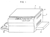
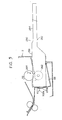
- the illustrated electrostatic copying apparatus has a substantially rectangular housing shown generally at 2.
- an original-support mechanism 4 for supporting an original document to be copied.
- the original-support mechanism 4 comprises a support frame 6 mounted movably for scanning of the original document by a suitable method (in the left and right-hand directions in Figure 2), a transparent plate 8 ( Figure 2) fixed to the support frame 6 and adapted to receive the original document thereon, and an original-holding member 10 which has one edge portion (the edge portion located in the upper part in Figure 1) connected pivotably to the support frame 6 and which can be turned by a manual operation between a closed position in which it covers the transparent plate 8 and the original document placed on it (the position shown in Figures 1 and 2) and an open position in which the transparent plate 8 and the original document on it are brought into view.
- the original-support mechanism 4 is preferably of such a type that when the electrostatic copying apparatus is in an inoperative state, it stops at a stop position shown by a solid line in Figures 1 and 2, but when the copying apparatus is set in operation and the copying process is performed, it makes a preparatory movement from the stop position to a scanning movement starting position shown by a two-dot chain line 4A in Figure 2 in the right-hand direction, then makes a scanning movement from this start position to a scanning movement-ending position shown by a two-dot chain line 4B in Figure 2 in the left-hand direction, and thereafter, returns to the stop position in the right-hand direction in Figure 2.
- operating elements such as a main switch, a knob for setting the number of copies required, and a knob for adjusting the intensity of exposure and display elements such as a display lamp, which are all known per se.
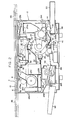
- a cylindrical rotary drum 12 is rotatably mounted within the housing 2 and is adapted to be driven by a main electric motor (not shown).
- a photo-sensitive member (not shown) is disposed in a conventional manner on at least a part of the peripheral surface of the rotary drum 12. Accordingly, the photosensitive member is moved by the rotation of the rotary drum 12 through a circular endless moving path defined by the peripheral surface of the rotary drum 12.
- an endless belt-like material known well to those skilled in the art may be mounted within the housing 2, and a photo- sensitive member may be disposed on at least a part of the surface of the endless belt-like member. In this alternative construction, the photosensitive member is moved through an endless moving path defined by the surface of the endless belt-like member.
- a latent electrostatic image-forming zone 16 Along the peripheral surface of the rotary drum 12 rotated in the direction of an arrow 14, therefore along the moving path of the photosensitive member on the rotary drum 12, are disposed a latent electrostatic image-forming zone 16, a developing zone 18 and a transfer zone 20 in this order when viewed in the moving direction of the photosensitive member.
- a charging corona-discharge device 22 for applying corona discharge to the surface of the photo- sensitive member to charge it to a specified polarity.
- a developing device 24 is provided within the developing zone 18, which functions both as a developing means for applying toner particles to a latent electrostatic image formed on the photosensitive member to develop it and as a cleaning means for removing residual toner particles from the photosensitive member after the transfer of a developed image to a copying paper in the transfer zone 20.
- the transfer zone 20 includes therein a transfer corona-discharge device 26 for applying corona discharge to the back surface of the copying paper at the time of transferring a developed image on the photo- sensitive member to the copying paper.
- a charge-eliminating corona-discharge device 28 and a charge eliminating lamp 30 for removing residual charges on the photosensitive member after the transfer of a developed image on the photosensitive member to a copying paper in the transfer zone 20 are disposed downstream of the transfer zone 20 and upstream of the latent electrostatic image forming zone 16 viewed in the rotating direction of the rotary drum 12 shown by the arrow 14, and therefore in the moving direction of the photosensitive member.
- the charge-eliminating corona-discharge device 28 applies corona discharge to the photosensitive member for charge elimination, and the charge-eliminating lamp 30 exposes the entire surface of the photosensitive member to light.
- An optical unit 32 for projecting the image of an original document placed on the transparent plate 8 of the original-support mechanism 4 onto the photosensitive member is disposed above the rotary drum 12 within the housing 2.
- the optical unit 32 includes an illuminating lamp 36 for illuminating the original document through an exposure opening 34 formed on the top surface of the housing 2, and a first reflecting mirror 38, an in-mirror lens 40, a second reflecting mirror 42 and a third reflecting mirror 44 for projecting the light reflected from the original document onto the photosensitive member.
- the optical unit 32 projects the image of the original document placed on the transparent plate 8 onto the photo- sensitive member at a position immediately downstream of the charging corona-discharge device 22 in the rotating direction of the rotating drum 12 in the latent electrostatic image-forming zone 16.
- the image of the original document is scanned and optically projected on the photosensitive member by moving the original-support mechanism 4 in a scanning manner.
- the image of the original document can also be scanned and optically projected on the photosensitive member by scanningly moving at least a part of the optical unit.
- a paper transfer unit shown generally at 46 is also provided in the illustrated electrostatic copying apparatus.
- the paper transfer unit 46 includes a paper-feed mechanism 54 consisting of a paper cassette 50 whose end is inserted into a cassette-receiving section 48 within the housing 2 through an opening formed in the right-hand end wall of the housing 2 and a paper feed roller 52 for feeding copying paper sheets one by one from the paper cassette 50 by being rotationally driven while being in engagement with the topmost sheet of a stack of paper sheets in the paper cassette 50 through an opening formed on the top surface of the paper cassette 50.
- the paper transfer unit 46 also comprises a pair of transfer rollers 55 for transferring the paper sheet delivered by the action of the paper feed roller 52 to the transfer zone 20 and a separator roller 56 for separating the copying paper adhering closely to the surface of the photo-sensitive member on the rotary drum 12 in the transfer zone 20 from the photosensitive member and carrying it away from the transfer zone 20.
- the copying paper carried away from the transfer zone 20 moves through a fixing mechanism shown generally at 58 for fixing the developed image on the copying paper and is discharged into a receiver tray 60 from a discharge opening formed in the left-hand end wall of the housing 2.
- the paper transfer unit 46 is of the type provided with the paper feed mechanism 54 utilizing the paper cassette 50. In place of, or in addition to, the paper feed mechanism 54, a paper feed mechanism of the type adapted to unwind a roll of copying paper, cut it to a required length and deliver it may be provided in the paper transfer unit 46.
- the operation of the electrostatic copying apparatus described above is described briefly hereinafter. While the rotary drum 12 is being rotated in the direction of the arrow 14, a latent electrostatic image is formed on the surface of the photosensitive member in the latent electrostatic image-forming zone 16. Specifically, the latent electrostatic image is formed by applying corona discharge to the photosensitive member by means of the charging corona-discharge device 22 to charge it to a specified polarity, and then projecting the image of an origianl document placed on the transparent plate 8 onto the charged photosensitive member by means of the optical unit 32.
- the original-support mechanism 4 In projecting the image of the original document onto the photosensitive member by the optical unit 32, the original-support mechanism 4 is caused to make a scanning movement from the scanning movement starting position shown by the two-dot chain line 4A to the scanning movement ending position shown by the two-dot chain line 4B in the left-hand direction in Figure 2. Then, in the developing zone 18, toner particles are applied to the latent electrostatic image on the photosensitive member by the action of the developing device 24, thereby developing the latent electrostatic image on the photosensitive member. In the meantime, the paper transfer unit 46 transfers a copying paper to the transfer zone 20 in synchronism with the rotation of the rotary drum 12, and in the transfer zone 20, the developed image on the photosensitive member is transferred to the copying paper.
- the copying paper having the developed image transferred thereto is fixed by the fixing mechanism 58 and then discharged into the receiver tray 60.
- the rotary drum 12 continues to rotate through at least one turn, preferably through two or more turns, after the developed image on the photosensitive member has been transferred to the copying paper, and during this period, the residual charge on the photosensitive member is removed by the action of the charge-eliminating lamp 30. Furthermore, by the functioning of the developing device 24 as a cleaning means, the residual toner on the photosensitive member is removed.
- the paper cassette 50 in normal use the paper cassette 50 is mounted on the cassette-receiving section 48 of the paper transfer unit 46 mentioned hereinabove with reference to Figure 2, and in performing the copying process, a copying paper sheet of a predetermined size carried by the cassette 50 is supplied to a paper transfer passage and a developed image, corresponding to the image of an original document to be copied, is formed on this predetermined-sized copying paper sheet.
- the present apparatus is equipped with a manual paper-positioning mechanism which can be mounted on the cassette-receiving section 48 in place of the paper cassette 50 and is adapted to enable a copying paper to be positioned manually so that it can be fed to the copying paper transfer passage by the action of the paper feed roller 52 provided in the cassette-receiving section 48.
- a manual paper-positioning mechanism which can be mounted on the cassette-receiving section 48 in place of the paper cassette 50 and is adapted to enable a copying paper to be positioned manually so that it can be fed to the copying paper transfer passage by the action of the paper feed roller 52 provided in the cassette-receiving section 48.
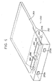
- the manual paper-positioning mechanism shown generally at 250 includes a frame 252. At least a front end portion of the frame 252 has a contour similar to the front end portion of the paper cassette 50 so that it can be inserted into the cassette-receiving section 48 of the housing 2 and be mounted in position in place of the paper cassette 50 ( Figure 2).
- the top surface of the frame 252 defines a preferably flat guide top surface 254 for guiding a copying paper which is to be positioned as required by a manual operation (namely, in such a manner that the paper may be fed into the paper transfer passage by the action of the paperfeed roller 52).
- a protruding part 256 whose inside surface defines an upstanding guide surface for guiding one edge of at least a front end portion of a copying paper to be positioned manually as required.
- At least one (two in the drawings) opening 258 is formed in the top surface of the frame 252 which defines the guide top surface 254.
- a shaft 260 is rotatably mounted in the front end portion of the frame 252, and auxiliary rollers 262 are fixed to the shaft 260 with the upper portions of their peripheral surfaces projecting upwards through the openings 258.
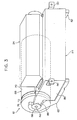
- the manual paper-positioning mechanism 250 described above is mounted on the cassette-receiving section 48 of the housing 2 as shown in Figure 5 in place of the paper cassette 50 ( Figure 2).
- the peripheral surfaces of the auxiliary rollers 262 of the manual paper-positioning mechanism 250 come into engagement with the peripheral surface of the paper feed roller 52 disposed in the cassette-receiving section 48.
Landscapes
- Physics & Mathematics (AREA)
- General Physics & Mathematics (AREA)
- Engineering & Computer Science (AREA)
- Environmental & Geological Engineering (AREA)
- Plasma & Fusion (AREA)
- Atmospheric Sciences (AREA)
- Biodiversity & Conservation Biology (AREA)
- Ecology (AREA)
- Microelectronics & Electronic Packaging (AREA)
- Environmental Sciences (AREA)
- Life Sciences & Earth Sciences (AREA)
- Electrophotography Configuration And Component (AREA)
- Electrostatic Charge, Transfer And Separation In Electrography (AREA)
- Dry Development In Electrophotography (AREA)
- Control Or Security For Electrophotography (AREA)
- Sheets, Magazines, And Separation Thereof (AREA)
- Paper Feeding For Electrophotography (AREA)
- Combination Of More Than One Step In Electrophotography (AREA)
Claims (2)
Applications Claiming Priority (2)
| Application Number | Priority Date | Filing Date | Title |
|---|---|---|---|
| JP4949780A JPS56146155A (en) | 1980-04-15 | 1980-04-15 | Electrostatic copying machine |
| JP49497/80 | 1980-04-15 |
Related Parent Applications (1)
| Application Number | Title | Priority Date | Filing Date |
|---|---|---|---|
| EP81301661.5 Division | 1981-04-15 |
Publications (2)
| Publication Number | Publication Date |
|---|---|
| EP0166874A1 EP0166874A1 (fr) | 1986-01-08 |
| EP0166874B1 true EP0166874B1 (fr) | 1988-08-10 |
Family
ID=12832775
Family Applications (6)
| Application Number | Title | Priority Date | Filing Date |
|---|---|---|---|
| EP85103866A Expired EP0166873B1 (fr) | 1980-04-15 | 1981-04-15 | Machine à copier électrostatique |
| EP85103864A Expired EP0166871B1 (fr) | 1980-04-15 | 1981-04-15 | Machine à copier électrostatique |
| EP85103868A Expired EP0166874B1 (fr) | 1980-04-15 | 1981-04-15 | Machine à copier électrostatique |
| EP81301661A Expired - Lifetime EP0038220B2 (fr) | 1980-04-15 | 1981-04-15 | Machine à copier électrostatique |
| EP85103867A Expired EP0167716B1 (fr) | 1980-04-15 | 1981-04-15 | Machine à copier électrostatique |
| EP85103865A Withdrawn EP0166872A1 (fr) | 1980-04-15 | 1981-04-15 | Machine à copier électrostatique |
Family Applications Before (2)
| Application Number | Title | Priority Date | Filing Date |
|---|---|---|---|
| EP85103866A Expired EP0166873B1 (fr) | 1980-04-15 | 1981-04-15 | Machine à copier électrostatique |
| EP85103864A Expired EP0166871B1 (fr) | 1980-04-15 | 1981-04-15 | Machine à copier électrostatique |
Family Applications After (3)
| Application Number | Title | Priority Date | Filing Date |
|---|---|---|---|
| EP81301661A Expired - Lifetime EP0038220B2 (fr) | 1980-04-15 | 1981-04-15 | Machine à copier électrostatique |
| EP85103867A Expired EP0167716B1 (fr) | 1980-04-15 | 1981-04-15 | Machine à copier électrostatique |
| EP85103865A Withdrawn EP0166872A1 (fr) | 1980-04-15 | 1981-04-15 | Machine à copier électrostatique |
Country Status (5)
| Country | Link |
|---|---|
| US (6) | US4382674A (fr) |
| EP (6) | EP0166873B1 (fr) |
| JP (1) | JPS56146155A (fr) |
| CA (1) | CA1174724A (fr) |
| DE (1) | DE3175958D1 (fr) |
Families Citing this family (46)
| Publication number | Priority date | Publication date | Assignee | Title |
|---|---|---|---|---|
| US4468113A (en) * | 1981-10-12 | 1984-08-28 | Konishiroku Photo Industry Co., Ltd. | Transfer type electrostatic reproducing apparatus |
| JPS5865674A (ja) * | 1981-10-16 | 1983-04-19 | Ricoh Co Ltd | プリンタ |
| US4613227A (en) * | 1982-02-08 | 1986-09-23 | Canon Kabushiki Kaisha | Image forming apparatus |
| JPS5939629A (ja) * | 1982-08-31 | 1984-03-05 | Konishiroku Photo Ind Co Ltd | 給紙用ユニバ−サルカセツト |
| JPS5986074A (ja) * | 1982-11-09 | 1984-05-18 | Ricoh Co Ltd | 電子写真複写機におけるトナ−補給量の制御方法 |
| JPH0619602B2 (ja) * | 1983-02-28 | 1994-03-16 | 株式会社東芝 | 画像形成装置 |
| JPS59198475A (ja) * | 1983-04-26 | 1984-11-10 | Toshiba Corp | 像形成装置 |
| JPS6078462A (ja) * | 1983-10-06 | 1985-05-04 | Konishiroku Photo Ind Co Ltd | 記録装置 |
| US4639114A (en) * | 1983-10-25 | 1987-01-27 | Kabushiki Kaisha Toshiba | Image-forming apparatus with automatic and manual paper feed modes |
| JPS60182453A (ja) * | 1984-02-29 | 1985-09-18 | Mita Ind Co Ltd | 複写機 |
| JPS60191279A (ja) * | 1984-03-13 | 1985-09-28 | Fuji Xerox Co Ltd | 複写機の制御方法 |
| JPS6132867A (ja) * | 1984-07-26 | 1986-02-15 | Konishiroku Photo Ind Co Ltd | 静電記録装置 |
| JPS6132864A (ja) * | 1984-07-26 | 1986-02-15 | Konishiroku Photo Ind Co Ltd | 静電記録装置 |
| JPS6156370A (ja) * | 1984-08-28 | 1986-03-22 | Ricoh Co Ltd | 画像形成装置 |
| JPS6193463A (ja) * | 1984-10-15 | 1986-05-12 | Fuji Photo Film Co Ltd | 電子写真装置における黒枠除去方法 |
| US4821067A (en) * | 1985-10-31 | 1989-04-11 | Kabushiki Kaisha Toshiba | Microfilm reader-printer having an image fermation device |
| JPH0697365B2 (ja) * | 1985-11-29 | 1994-11-30 | 三田工業株式会社 | 感光体の帯電領域制御装置 |
| JPS62262062A (ja) * | 1986-05-07 | 1987-11-14 | Canon Inc | 画像形成装置 |
| JPS63212624A (ja) * | 1987-02-27 | 1988-09-05 | Canon Inc | シ−ト給送装置 |
| US5008711A (en) * | 1987-04-23 | 1991-04-16 | Ricoh Company, Ltd. | Image forming apparatus |
| JPH01198770A (ja) * | 1987-10-16 | 1989-08-10 | Ricoh Co Ltd | 複写機の制御装置 |
| JP2578841B2 (ja) * | 1987-11-12 | 1997-02-05 | キヤノン株式会社 | 画像形成装置 |
| US5307132A (en) * | 1987-11-12 | 1994-04-26 | Canon Kabushiki Kaisha | Image forming apparatus having a controller for discharging air in response to a heating condition of an image fixing device |
| US4908661A (en) * | 1987-11-27 | 1990-03-13 | Ricoh Company, Ltd. | Holder device for handling an image carrier of an image forming apparatus |
| US4819026A (en) * | 1987-12-21 | 1989-04-04 | Xerox Corporation | Cleaning apparatus for a charge retentive surface |
| US5179636A (en) * | 1988-03-08 | 1993-01-12 | Canon Kabushiki Kaisha | Recording apparatus |
| JP3004990B2 (ja) * | 1988-03-08 | 2000-01-31 | キヤノン株式会社 | プリンタ |
| JP2667440B2 (ja) * | 1988-05-18 | 1997-10-27 | 株式会社東芝 | 画像形成装置 |
| JPH01303252A (ja) * | 1988-05-30 | 1989-12-07 | Fujitsu Ltd | 画像印刷装置 |
| JPH0275653U (fr) * | 1988-11-29 | 1990-06-11 | ||
| JPH02163764A (ja) * | 1988-12-16 | 1990-06-25 | Minolta Camera Co Ltd | 複写機 |
| US5038170A (en) * | 1989-03-30 | 1991-08-06 | Kabushiki Kaisha Toshiba | Cooling system for an image forming apparatus |
| JP2854611B2 (ja) * | 1989-07-07 | 1999-02-03 | キヤノン株式会社 | 画像形成装置 |
| JPH03147629A (ja) * | 1989-11-01 | 1991-06-24 | Ricoh Co Ltd | 記録紙長検知装置 |
| US5140463A (en) * | 1990-03-08 | 1992-08-18 | Yoo Kwong M | Method and apparatus for improving the signal to noise ratio of an image formed of an object hidden in or behind a semi-opaque random media |
| JPH04151177A (ja) * | 1990-04-10 | 1992-05-25 | Asahi Optical Co Ltd | トナー供給促進機構 |
| US5442421A (en) * | 1990-10-01 | 1995-08-15 | Canon Kabushiki Kaisha | Process cartridge and image forming apparatus using the same |
| JP2577840B2 (ja) * | 1991-10-17 | 1997-02-05 | 三田工業株式会社 | 給紙カセットケース |
| JP2629509B2 (ja) * | 1991-12-17 | 1997-07-09 | 村田機械株式会社 | クリーナレス画像形成装置 |
| JP3131286B2 (ja) * | 1992-05-27 | 2001-01-31 | 沖電気工業株式会社 | 電子写真プリンタ |
| JP3224688B2 (ja) * | 1994-06-07 | 2001-11-05 | キヤノン株式会社 | 画像形成装置 |
| US5477307A (en) * | 1994-09-14 | 1995-12-19 | Xerox Corporation | Apparatus for dispersing and/or transporting particulates |
| US5799228A (en) * | 1995-06-09 | 1998-08-25 | Ricoh Company, Ltd. | Image forming apparatus which prevents adverse affects from heating elements |
| US6510291B2 (en) | 2001-04-19 | 2003-01-21 | Lexmark International, Inc | Toner supply with level sensor and meter and method of using the same |
| JP5393765B2 (ja) * | 2011-12-19 | 2014-01-22 | 京セラドキュメントソリューションズ株式会社 | 現像装置及びそれを備えた画像形成装置 |
| JP6701855B2 (ja) * | 2016-03-22 | 2020-05-27 | コニカミノルタ株式会社 | 画像形成装置 |
Family Cites Families (53)
| Publication number | Priority date | Publication date | Assignee | Title |
|---|---|---|---|---|
| US3114020A (en) * | 1961-05-05 | 1963-12-10 | Beckman Instruments Inc | High resolution digital position transducer including a magnetic switch |
| US3308713A (en) * | 1963-09-30 | 1967-03-14 | Documentation Inc | Portable reader printer |
| US3588472A (en) * | 1966-11-18 | 1971-06-28 | Xerox Corp | Logic control apparatus |
| FR1568821A (fr) † | 1967-09-20 | 1969-05-30 | ||
| US3684363A (en) * | 1969-08-30 | 1972-08-15 | Canon Kk | Device for separating recording medium for use in electrophotographic copying machines |
| CA939732A (en) | 1969-11-11 | 1974-01-08 | Masayoshi Furuichi | Apparatus for supplementing toner in electrophotographic machines |
| US3647293A (en) * | 1970-12-01 | 1972-03-07 | Ibm | Copying system featuring combined developing-cleaning station alternately activated |
| US3637306A (en) * | 1970-12-02 | 1972-01-25 | Ibm | Copying system featuring alternate developing and cleaning of successive image areas on photoconductor |
| US3692403A (en) * | 1971-12-23 | 1972-09-19 | Xerox Corp | Automatic control of toner concentrations |
| JPS52517Y2 (fr) * | 1971-12-27 | 1977-01-08 | ||
| JPS48105531U (fr) * | 1972-03-09 | 1973-12-08 | ||
| NL7305054A (fr) * | 1972-04-13 | 1973-10-16 | ||
| JPS4912829A (fr) * | 1972-04-17 | 1974-02-04 | ||
| US3851966A (en) * | 1972-12-11 | 1974-12-03 | Xerox Corp | Reproduction apparatus |
| US3890721A (en) * | 1972-12-26 | 1975-06-24 | Canon Kk | Developing liquid recovery device in a copying machine |
| JPS5422090B2 (fr) * | 1973-04-28 | 1979-08-04 | ||
| JPS5225152Y2 (fr) * | 1973-05-18 | 1977-06-08 | ||
| US3936184A (en) * | 1973-05-25 | 1976-02-03 | Canon Kabushiki Kaisha | Electrophotographic copying machine |
| BE821850A (nl) * | 1973-11-12 | 1975-05-05 | Elektrofotografisch kopieerapparaat | |
| JPS5099146A (fr) * | 1973-12-27 | 1975-08-06 | ||
| AT335195B (de) * | 1974-07-17 | 1977-02-25 | Philips Nv | Aufzeichnungs- und/oder wiedergabegerat und kassette fur ein solches gerat |
| JPS5122206A (en) * | 1974-08-16 | 1976-02-21 | Shimizu Construction Co Ltd | Suraimujokyosochi |
| US3944356A (en) * | 1974-08-29 | 1976-03-16 | Xerox Corporation | Charging apparatus |
| US3950092A (en) | 1974-09-20 | 1976-04-13 | Xerox Corporation | Impeller member for use in transporting particulate material in a reproducing machine |
| US4178092A (en) * | 1974-11-30 | 1979-12-11 | Minolta Camera Kabushiki Kaisha | Electrophotographic copying apparatus with gas evacuating means |
| US4122981A (en) * | 1975-10-18 | 1978-10-31 | Minolta Camera Kabushiki Kaisha | Toner dispensing device having reciprocating dispensing plate and agitator |
| JPS5256939A (en) | 1975-11-06 | 1977-05-10 | Fuji Xerox Co Ltd | Developing apparatus for electronic copying machine |
| JPS5273749U (fr) † | 1975-11-28 | 1977-06-02 | ||
| DE2618089A1 (de) * | 1976-04-24 | 1977-11-10 | Agfa Gevaert Ag | Vorrichtung zum einfuehren eines einzelnen blattfoermigen kopietraegers in die kopietraegertransportbahn eines kopiergeraetes |
| DE2729591A1 (de) * | 1976-06-30 | 1978-01-12 | Minolta Camera Kk | Elektrophotographisches kopiergeraet |
| JPS5952830B2 (ja) * | 1977-02-01 | 1984-12-21 | キヤノン株式会社 | 画像形成装置の空気流路 |
| US4204668A (en) * | 1977-05-17 | 1980-05-27 | Ricoh Company, Ltd. | Paper feeding apparatus |
| FR2406239A1 (fr) † | 1977-05-31 | 1979-05-11 | Canon Kk | Appareil de formation d'images a format reglable automatiquement |
| DE2729349C3 (de) | 1977-06-29 | 1981-06-25 | Agfa-Gevaert Ag, 5090 Leverkusen | Elektrostatisches Kopiergerät |
| US4270487A (en) * | 1977-10-27 | 1981-06-02 | Hitachi, Ltd. | Developer regulating device in developing apparatus |
| JPS5474441A (en) † | 1977-11-26 | 1979-06-14 | Canon Inc | Copying machine |
| JPS5497041A (en) * | 1978-01-17 | 1979-07-31 | Konishiroku Photo Ind Co Ltd | Zerographic copier |
| JPS5497968A (en) * | 1978-01-19 | 1979-08-02 | Ricoh Co Ltd | Cassette paper feeder |
| JPS5930254B2 (ja) * | 1978-03-09 | 1984-07-26 | ミノルタ株式会社 | 複写領域表示装置 |
| US4259008A (en) * | 1978-04-14 | 1981-03-31 | Mita Industrial Company, Ltd. | Electrostatic copying apparatus |
| JPS54137347A (en) * | 1978-04-18 | 1979-10-25 | Olympus Optical Co Ltd | Zerographic apparatus |
| US4213110A (en) * | 1978-07-20 | 1980-07-15 | Holce Thomas J | Proximity switch having adjustable sensitivity |
| US4347299A (en) | 1978-08-16 | 1982-08-31 | Minolta Camera Kabushiki Kaisha | Method of controlling toner concentration for electrophotographic copying apparatus |
| JPS5543564A (en) † | 1978-09-22 | 1980-03-27 | Ricoh Co Ltd | Electrophotographic copying method |
| US4325626A (en) * | 1978-12-13 | 1982-04-20 | Mita Industrial Co., Ltd. | Electrostatic copying apparatus |
| JPS6054660B2 (ja) * | 1979-02-02 | 1985-11-30 | オリンパス光学工業株式会社 | 電子写真装置 |
| US4344692A (en) | 1979-03-15 | 1982-08-17 | Tokyo Shibaura Denki Kabushiki Kaisha | Developer transportation device for electrostatic copying machine |
| US4297029A (en) * | 1979-04-09 | 1981-10-27 | Xerox Corporation | Apparatus and method for diagnostic entry |
| JPS567841A (en) * | 1979-06-25 | 1981-01-27 | Canon Inc | Containing apparatus for copying material |
| US4214696A (en) | 1979-06-27 | 1980-07-29 | Container Corporation Of America | Container with integral partition |
| US4243316A (en) * | 1979-07-25 | 1981-01-06 | Eastman Kodak Company | Registration mechanism |
| JPS6036585B2 (ja) | 1979-11-24 | 1985-08-21 | 株式会社日立製作所 | 現像装置 |
| JPS56137362A (en) * | 1980-03-28 | 1981-10-27 | Minolta Camera Co Ltd | Counter controlling device |
-
1980
- 1980-04-15 JP JP4949780A patent/JPS56146155A/ja active Granted
-
1981
- 1981-04-03 US US06/250,829 patent/US4382674A/en not_active Expired - Lifetime
- 1981-04-06 CA CA000374708A patent/CA1174724A/fr not_active Expired
- 1981-04-15 EP EP85103866A patent/EP0166873B1/fr not_active Expired
- 1981-04-15 EP EP85103864A patent/EP0166871B1/fr not_active Expired
- 1981-04-15 EP EP85103868A patent/EP0166874B1/fr not_active Expired
- 1981-04-15 DE DE8181301661T patent/DE3175958D1/de not_active Expired
- 1981-04-15 EP EP81301661A patent/EP0038220B2/fr not_active Expired - Lifetime
- 1981-04-15 EP EP85103867A patent/EP0167716B1/fr not_active Expired
- 1981-04-15 EP EP85103865A patent/EP0166872A1/fr not_active Withdrawn
-
1983
- 1983-02-08 US US06/465,062 patent/US4436411A/en not_active Expired - Lifetime
- 1983-02-08 US US06/465,063 patent/US4478507A/en not_active Expired - Lifetime
- 1983-02-08 US US06/464,833 patent/US4515465A/en not_active Expired - Lifetime
- 1983-02-14 US US06/465,970 patent/US4469431A/en not_active Expired - Lifetime
- 1983-02-14 US US06/465,973 patent/US4469432A/en not_active Expired - Lifetime
Also Published As
| Publication number | Publication date |
|---|---|
| JPS646458B2 (fr) | 1989-02-03 |
| EP0166874A1 (fr) | 1986-01-08 |
| EP0038220B1 (fr) | 1987-03-04 |
| EP0167716B1 (fr) | 1989-08-30 |
| EP0167716A1 (fr) | 1986-01-15 |
| US4469432A (en) | 1984-09-04 |
| JPS56146155A (en) | 1981-11-13 |
| CA1174724A (fr) | 1984-09-18 |
| EP0166871B1 (fr) | 1988-11-09 |
| DE3175958D1 (en) | 1987-04-09 |
| EP0038220A2 (fr) | 1981-10-21 |
| US4515465A (en) | 1985-05-07 |
| EP0038220A3 (en) | 1983-01-12 |
| EP0166873A1 (fr) | 1986-01-08 |
| EP0166871A1 (fr) | 1986-01-08 |
| US4436411A (en) | 1984-03-13 |
| EP0038220B2 (fr) | 1991-10-16 |
| US4478507A (en) | 1984-10-23 |
| EP0166872A1 (fr) | 1986-01-08 |
| EP0166873B1 (fr) | 1989-06-21 |
| US4469431A (en) | 1984-09-04 |
| US4382674A (en) | 1983-05-10 |
Similar Documents
| Publication | Publication Date | Title |
|---|---|---|
| EP0166874B1 (fr) | Machine à copier électrostatique | |
| EP0346454B1 (fr) | Appareil de nettoyage a double fonction | |
| US4167326A (en) | Contact electrostatic photocopying process and apparatus forming reversed image master using web-type photoconductive surface | |
| US4460269A (en) | Automatic document feeder for use in combination with an electrophotographic copying machine | |
| US3139013A (en) | Document reproducing apparatus | |
| JPS619671A (ja) | 電子写真複写機における複写画像の部分撮り方法およびそのための装置 | |
| JPH0326832B2 (fr) | ||
| JPS6242267B2 (fr) | ||
| JP2687582B2 (ja) | 画像形成装置 | |
| JPS60177371A (ja) | 複写装置等における現像装置の逃避装置 | |
| JPH0635384A (ja) | クリーニング装置 | |
| JPH0511565Y2 (fr) | ||
| JPH0764461A (ja) | 画像形成装置 | |
| JPH0353228Y2 (fr) | ||
| JPS60241080A (ja) | 画像形成装置 | |
| KR920005086Y1 (ko) | 전자 사진 기록장치의 정착기 | |
| JPS61250662A (ja) | 画像形成装置 | |
| JPS6337392B2 (fr) | ||
| JP2920647B2 (ja) | 静電印刷装置 | |
| JPH0475506B2 (fr) | ||
| JP2578619B2 (ja) | 静電記録装置の画像形成方法 | |
| JPS6311961A (ja) | 静電複写機 | |
| JPH0746255B2 (ja) | 画像形成装置 | |
| JPH0243182B2 (fr) | ||
| JPH0332066B2 (fr) |
Legal Events
| Date | Code | Title | Description |
|---|---|---|---|
| PUAI | Public reference made under article 153(3) epc to a published international application that has entered the european phase |
Free format text: ORIGINAL CODE: 0009012 |
|
| AC | Divisional application: reference to earlier application |
Ref document number: 38220 Country of ref document: EP |
|
| AK | Designated contracting states |
Designated state(s): DE FR GB IT NL |
|
| 17P | Request for examination filed |
Effective date: 19860307 |
|
| 17Q | First examination report despatched |
Effective date: 19871215 |
|
| GRAA | (expected) grant |
Free format text: ORIGINAL CODE: 0009210 |
|
| AC | Divisional application: reference to earlier application |
Ref document number: 38220 Country of ref document: EP |
|
| AK | Designated contracting states |
Kind code of ref document: B1 Designated state(s): DE FR GB IT NL |
|
| ITF | It: translation for a ep patent filed |
Owner name: ING. C. GREGORJ S.P.A. |
|
| REF | Corresponds to: |
Ref document number: 3176839 Country of ref document: DE Date of ref document: 19880915 |
|
| ET | Fr: translation filed | ||
| PLBE | No opposition filed within time limit |
Free format text: ORIGINAL CODE: 0009261 |
|
| STAA | Information on the status of an ep patent application or granted ep patent |
Free format text: STATUS: NO OPPOSITION FILED WITHIN TIME LIMIT |
|
| 26N | No opposition filed | ||
| ITTA | It: last paid annual fee | ||
| PGFP | Annual fee paid to national office [announced via postgrant information from national office to epo] |
Ref country code: GB Payment date: 19970407 Year of fee payment: 17 |
|
| PGFP | Annual fee paid to national office [announced via postgrant information from national office to epo] |
Ref country code: FR Payment date: 19970409 Year of fee payment: 17 |
|
| PGFP | Annual fee paid to national office [announced via postgrant information from national office to epo] |
Ref country code: DE Payment date: 19970418 Year of fee payment: 17 |
|
| PGFP | Annual fee paid to national office [announced via postgrant information from national office to epo] |
Ref country code: NL Payment date: 19970428 Year of fee payment: 17 |
|
| PG25 | Lapsed in a contracting state [announced via postgrant information from national office to epo] |
Ref country code: GB Free format text: LAPSE BECAUSE OF NON-PAYMENT OF DUE FEES Effective date: 19980415 |
|
| PG25 | Lapsed in a contracting state [announced via postgrant information from national office to epo] |
Ref country code: FR Free format text: THE PATENT HAS BEEN ANNULLED BY A DECISION OF A NATIONAL AUTHORITY Effective date: 19980430 |
|
| PG25 | Lapsed in a contracting state [announced via postgrant information from national office to epo] |
Ref country code: NL Free format text: LAPSE BECAUSE OF NON-PAYMENT OF DUE FEES Effective date: 19981101 |
|
| GBPC | Gb: european patent ceased through non-payment of renewal fee |
Effective date: 19980415 |
|
| NLV4 | Nl: lapsed or anulled due to non-payment of the annual fee |
Effective date: 19981101 |
|
| PG25 | Lapsed in a contracting state [announced via postgrant information from national office to epo] |
Ref country code: DE Free format text: LAPSE BECAUSE OF NON-PAYMENT OF DUE FEES Effective date: 19990202 |
|
| REG | Reference to a national code |
Ref country code: FR Ref legal event code: ST |