EP0165434B1 - Module de plaque de circuit imprimé en forme de boîtier - Google Patents
Module de plaque de circuit imprimé en forme de boîtier Download PDFInfo
- Publication number
- EP0165434B1 EP0165434B1 EP85105651A EP85105651A EP0165434B1 EP 0165434 B1 EP0165434 B1 EP 0165434B1 EP 85105651 A EP85105651 A EP 85105651A EP 85105651 A EP85105651 A EP 85105651A EP 0165434 B1 EP0165434 B1 EP 0165434B1
- Authority
- EP
- European Patent Office
- Prior art keywords
- printed circuit
- circuit board
- plug
- terminal unit
- board module
- Prior art date
- Legal status (The legal status is an assumption and is not a legal conclusion. Google has not performed a legal analysis and makes no representation as to the accuracy of the status listed.)
- Expired
Links
Images


Classifications
-
- H—ELECTRICITY
- H05—ELECTRIC TECHNIQUES NOT OTHERWISE PROVIDED FOR
- H05K—PRINTED CIRCUITS; CASINGS OR CONSTRUCTIONAL DETAILS OF ELECTRIC APPARATUS; MANUFACTURE OF ASSEMBLAGES OF ELECTRICAL COMPONENTS
- H05K7/00—Constructional details common to different types of electric apparatus
- H05K7/14—Mounting supporting structure in casing or on frame or rack
- H05K7/1462—Mounting supporting structure in casing or on frame or rack for programmable logic controllers [PLC] for automation or industrial process control
- H05K7/1468—Mechanical features of input/output (I/O) modules
- H05K7/1469—Terminal blocks for connecting sensors
Definitions
- the invention relates to a box-shaped electronic printed circuit board assembly with screw terminals for connecting lines which can be actuated from the front and are designed as a plug-in unit, the connecting cable insertion openings of the screw connections running out in a longitudinal channel which is open towards the front, and the plug-in unit provided with a swivel joint can be contacted with a printed circuit board provided in the flat module .
- the arrangement described above is to be improved in such a way that while maintaining the convenient connection option from the front or the provision of sufficient space for labeling and for display purposes, the printed circuit boards can be arranged directly with their flat sides adjacent to one another on a carrier in a space-saving manner and while maintaining the convenient Possibility of connection in the form of plug-in connections also ensures an accurate and secure plug-in connection with the elimination of a relative movement between the printed circuit board and plug-in unit via intermediate parts without considerable effort.
- a cover designed as a labeling plate covers the longitudinal channel and the screw connections on the front of the printed circuit board and a plug connector adapted to the plug-in unit is electrically and mechanically connected to the printed circuit board and in that the plug-in unit is provided with a swivel joint, the counter bearing of which Plug connector is attached.
- the longitudinal channel is provided on the plug-in unit and the side wall opposite the screw connections is designed to be removable. This ensures that the lines are freely accessible.
- a separate cap is to be removed here, the accessibility for the screw connections being impaired by the fastening angle for the cap.
- an axially non-displaceably mounted fastening screw which can be screwed into a thread on the connector strip is arranged on the side of the control unit opposite the swivel joint.
- a reliable assignment of the designation for the luminescence diodes on the labeling plate can be achieved if the longitudinal channel is flanked on one side by the screw connections and adjacent luminescence diodes, the labeling plate lying directly next to the luminescence diodes in the operating state.
- the luminescent diodes should be more or less at the same height as the screw connections, but the printed circuit board can only start behind the screw connections, it is advantageous if the luminescent diodes are arranged in a holder that is electrically and mechanically connected to the printed circuit board. In order to ensure that settings or tests are only carried out by specialist personnel or only when the printed circuit boards are de-energized, it has proven to be advantageous if, seen from the front, the modules for protection and / or are accessible behind the plug-in unit after the plug-in unit has been swung out from the front Setting of working and measuring ranges in the flat module are attached.
- the modules are connected to the power strip via their side wall with a dovetail connection and are pressed against stops.
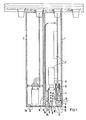
- the printed circuit board 1 is provided with the screw connections 3, which are combined with a plug-in unit 4 and contact 5 connections on the printed circuit board 6 with the contact springs.
- the electronic components 7 are fastened on the printed circuit board 6.
- the circuit board 6 is held in the usual manner in the printed circuit board and is also provided on the side opposite the front side with further plug connections for the internal wiring of several printed circuit boards with one another. Adjacent to the screw terminals 3 is a channel 8, in which the lines 9 can be guided, the ends 10 of which are stripped and inserted into the connecting line insertion openings 11 for connection to the screw terminals.
- the channel 8 is delimited on the opposite side by the wall 12, behind which are the luminescent diodes 13, which, when wired accordingly, serve as display means for the switching state of the printed circuit boards. They can be combined with the printed circuit board 6 to form an insertable unit and wired on the printed circuit board so that the luminescent diodes 13 lie on the outer wall 14 of the box-shaped housing of the printed circuit board assembly 1.
- the flat module 1 is covered by a labeling plate 15, which is folded from two plates 17 and 18 connected via the film hinge 16 and is connected to the box-shaped housing of the flat module by a snap connection.
- the one-piece label plate 15 can be designed as a pivotable door that has two film hinges: one for opening to insert the label and one for swinging out the flap part in order to access the vertical cable duct.
- the complete labeling plate 15 can be removed when replacing the module and snapped back onto the new module with the left labeling plate strip. This means that there is no need for re-labeling. After closing, the door is locked with the front connector. Inscriptions can also be attached to the inside of the labeling plate, if necessary.
- openings 19 are present in both plates 17 and 18, through which the luminescent diodes 13 can be recognized.
- Labeling fields 20 are also provided for a label sheet 21 clamped between the two plates 17 and 18. These labeling fields can consist of the plate 18 as a recess 22.
- the plate 18 can also be made transparent so that the inscription on the inscription sheet can be seen through the plate 18.
- the provision of the recess 22 has the advantage that the printed circuit board can be labeled by hand from the outside without opening the plate 18.
- the flat module 2 does not contain any screw connections 3, but is only contracted via the internal wiring described above, so that the writing plate 15 can be designed without labeling fields and openings 19 for the luminescent diodes.
- the plug-in unit 4 can be guided into the position shown in dashed lines in FIG. 1 and locked in this position.
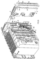
- handles 23 connected to the plug-in unit 4 can serve on the narrow side surfaces (as can be seen from FIGS. 2 and 3). If the plug-in unit is to be moved from the pre-wiring position shown in FIG. 2 to the one shown in FIG. 3, the latching 26 can be released by pressing a locking lever 24 in the direction of arrow 25 and the plug-in unit 4 by means of handles 23 for contacting the contact springs 4 are inserted with the connections of the circuit board 6.
- the locking lever 24 can be integrally formed on a locking part 27 which is locked with one of the rod-shaped guide parts 29 via the locking connection 30.
- the latching connection can be released via a detaching projection 28.
- the rod-shaped guide parts 29 are provided, for example, on the two narrow end faces 31 of the printed circuit boards and are equipped with threads 32 into which fastening screws for the labeling plates 15 are inserted. With metallic guide rods, these can also be used for shielding purposes, e.g. B. by ground contacting the LP shield surfaces riveted to the guide rods sliding contact springs. With the module removed, the guide rods can be used to fix the front connector so that they do not hang down freely on the cables.
- the positioning and assignment of the rod-shaped guide parts and bus cable slots can, for. B. can be effected via only laterally snap-in stops 33.
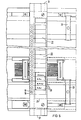
- a male connector 35 is provided on the side of the printed circuit board 6 facing the plug-in unit 4, which is firmly connected to the printed circuit board 6 by screws 36, as shown in FIG. 7.
- the connector strip 35 carries the connection lugs 37 to be electrically connected to the current paths of the printed circuit board 6, which merge into the knife-shaped plug connections 38.
- the plug connections 38 act with the Contact springs 5 of the plug-in unit 4 together when the plug-in unit is inserted.
- the contact springs 5 are in turn electrically connected to the screw connections 3 of the plug-in unit 4, preferably made from a stamped and bent part.
- the plug-in unit 4 is provided with a swivel joint 39, the counter bearing of which is present on the male connector 35.
- the plug-in unit 4 can be easily connected to the male connector 35 by hooking it in and thus produce the swivel joint by the plug-in unit 4 being pivotable in the direction of the arrow. Since the mounting on the male connector 35 is provided, the printed circuit board 6 remains practically without mechanical stresses, so that any interruptions in the printed circuit board 6 which may be caused thereby are avoided.
- the side wall 41 of the pivotable plug-in unit 4 can be removed.
- the pre-locking position can thus be dispensed with here.
- the screw connections 3 together with the luminescent diodes 13 lie on one side of the channel 8, a direct assignment of screw connections to luminescent diodes can be seen.
- the labeling plate 15 is open, the inside of the labeling plate can also be used for labeling purposes.
- a module 45 can be connected via dovetail connection 44 in such a way that it is accessible from the front of the flat module 1 after the plug-in unit 4 has been pivoted out.
- fuses 46 are shown, for example, which can be replaced from the front.
- a module 45 for protection a module for setting working or measuring ranges can also be inserted here.
- the luminescent diodes 13 are arranged in relation to the circuit board level in order to make room for the plug connections between the plug connector and the plug unit, such that they would be immersed in the bath when the circuit board was soldered.
- the luminescent diodes are accommodated in a holder 47 which is provided with grooves 48 for inserting the connecting lines 49 for the luminescent diodes 13.
- the ends of the connecting lines 49 are inserted into corresponding connection openings 50 in the printed circuit board 6.
- the holder has break-off pins 51 which are inserted into corresponding recesses in the printed circuit board 6 without making an electrical connection.
- the position of the holder 47 is indicated by dashed lines in FIG. 7. Since the luminescent diodes are now on the other side of the printed circuit board 6, the printed circuit board can be tinned without difficulty and the connections for the connecting lines 49 can thereby be produced.
- the pins 51 break off automatically when the luminescence diode holder is folded back into the operating position; the lines 49 can slip through corresponding slots in the holder and the holder 47 can latch with latches 52 around the circuit board 6 and assume the position shown in FIG. 7.
- the knife-shaped plug connections 38, the modules 45, and the holder 47 and thus the luminescence diodes 13 themselves and also the printed circuit boards 6 in the upper region are covered by a cap 53, which leaves space for the plug unit 4.
- a fastening screw 54 is rotatably mounted on the side opposite the swivel joint 39 against axial displacement and can be brought into engagement with a counter thread 55 in the plug connector 35 for pivoting in and unscrewing the plug unit.
Landscapes
- Engineering & Computer Science (AREA)
- Automation & Control Theory (AREA)
- Microelectronics & Electronic Packaging (AREA)
- Coupling Device And Connection With Printed Circuit (AREA)
- Mounting Of Printed Circuit Boards And The Like (AREA)
- Details Of Connecting Devices For Male And Female Coupling (AREA)
- Structures For Mounting Electric Components On Printed Circuit Boards (AREA)
- Led Device Packages (AREA)
- Transmitters (AREA)
- Electrophonic Musical Instruments (AREA)
- Container, Conveyance, Adherence, Positioning, Of Wafer (AREA)
Claims (7)
Priority Applications (1)
| Application Number | Priority Date | Filing Date | Title |
|---|---|---|---|
| AT85105651T ATE34504T1 (de) | 1984-05-21 | 1985-05-08 | Kastenfoermige flachbaugruppe. |
Applications Claiming Priority (2)
| Application Number | Priority Date | Filing Date | Title |
|---|---|---|---|
| DE3418844 | 1984-05-21 | ||
| DE19843418844 DE3418844A1 (de) | 1984-05-21 | 1984-05-21 | Kastenfoermige flachbaugruppe |
Related Child Applications (1)
| Application Number | Title | Priority Date | Filing Date |
|---|---|---|---|
| EP87110091.3 Division-Into | 1985-05-08 |
Publications (2)
| Publication Number | Publication Date |
|---|---|
| EP0165434A1 EP0165434A1 (fr) | 1985-12-27 |
| EP0165434B1 true EP0165434B1 (fr) | 1988-05-18 |
Family
ID=6236434
Family Applications (2)
| Application Number | Title | Priority Date | Filing Date |
|---|---|---|---|
| EP85105651A Expired EP0165434B1 (fr) | 1984-05-21 | 1985-05-08 | Module de plaque de circuit imprimé en forme de boîtier |
| EP87110091A Expired - Lifetime EP0268016B1 (fr) | 1984-05-21 | 1985-05-08 | Procédé de connexion d'une diode luminescente retenue dans un support avec un circuit imprimé |
Family Applications After (1)
| Application Number | Title | Priority Date | Filing Date |
|---|---|---|---|
| EP87110091A Expired - Lifetime EP0268016B1 (fr) | 1984-05-21 | 1985-05-08 | Procédé de connexion d'une diode luminescente retenue dans un support avec un circuit imprimé |
Country Status (9)
| Country | Link |
|---|---|
| US (1) | US5043847A (fr) |
| EP (2) | EP0165434B1 (fr) |
| JP (1) | JPS60261193A (fr) |
| AT (2) | ATE34504T1 (fr) |
| AU (1) | AU587976B2 (fr) |
| BR (1) | BR8502368A (fr) |
| CA (1) | CA1257680A (fr) |
| DE (3) | DE3418844A1 (fr) |
| IN (2) | IN163894B (fr) |
Cited By (3)
| Publication number | Priority date | Publication date | Assignee | Title |
|---|---|---|---|---|
| DE3603750A1 (de) * | 1986-02-06 | 1987-08-13 | Siemens Ag | Automatisierungsgeraet |
| DE3633785A1 (de) * | 1986-10-03 | 1988-04-07 | Siemens Ag | Automatisierungsgeraet |
| DE3822287A1 (de) * | 1988-07-01 | 1990-01-04 | Branscheid Gmbh | Vorrichtung zur halterung von leiterplatten in schaltschraenken od. dgl. |
Families Citing this family (55)
| Publication number | Priority date | Publication date | Assignee | Title |
|---|---|---|---|---|
| DE3603643C3 (de) * | 1986-02-06 | 1993-12-23 | Licentia Gmbh | Baugruppenträger für Baugruppen mit Automatisierungsgeräten |
| DE3624216A1 (de) * | 1986-07-15 | 1988-01-21 | Schleicher Relais | Gehaeuse zur aufnahme mindestens einer mit elektronischen bauelementen bestueckten leiterplatte |
| US4869681A (en) * | 1987-08-28 | 1989-09-26 | Siemens Aktiengesellschaft | Front plug system with lagging end contact arrangement |
| JPH0828587B2 (ja) * | 1988-03-12 | 1996-03-21 | ファナック株式会社 | I/oモジュール |
| US5253140A (en) * | 1988-03-12 | 1993-10-12 | Fanuc Ltd. | Connector unit for input/output module of programmable controller having disengagement lever |
| DE8911274U1 (fr) * | 1989-09-21 | 1989-11-16 | Siemens Ag, 1000 Berlin Und 8000 Muenchen, De | |
| DE58907795D1 (de) * | 1989-09-25 | 1994-07-07 | Siemens Ag | Baugruppe mit einer Leiterplatte. |
| DE69118792T2 (de) * | 1990-09-10 | 1996-08-29 | Yokogawa Electric Corp | Gehäuseanordnung für eine elektronische Anlage |
| EP0482418B1 (fr) * | 1990-10-24 | 1995-01-11 | Asea Brown Boveri Ag | Dispositif d'entrée ou/et sortie pour des données de processus |
| US5159534A (en) * | 1991-01-22 | 1992-10-27 | Johnson Service Company | Electronic/electromechanical packaging arrangement for facility management system |
| DE9104384U1 (fr) * | 1991-04-10 | 1991-06-06 | Siemens Ag, 8000 Muenchen, De | |
| DE4111912C2 (de) * | 1991-04-12 | 1993-10-14 | Kloeckner Moeller Gmbh | Leiterplattenanordnung und Kontaktvorrichtung für Steuersysteme |
| US5157590A (en) * | 1991-04-19 | 1992-10-20 | Square D Company | Mounting bracket for a programmable logic controller control module |
| GB9111534D0 (en) * | 1991-05-29 | 1991-07-17 | Measurement Tech Ltd | Electrical isolators |
| EP0536560B1 (fr) * | 1991-10-11 | 1996-06-12 | Asea Brown Boveri Ag | Dispositif d'entrée ou/et sortie pour données de processus |
| US5255322A (en) * | 1992-01-09 | 1993-10-19 | Square D Co. | Multi-zone audio distribution amplifier |
| DE9218990U1 (de) * | 1992-10-14 | 1996-09-19 | Siemens Ag | Steckanschlußsystem für eine elektronische Baugruppe |
| US5302136A (en) * | 1992-11-23 | 1994-04-12 | Modicon, Inc. | Apparatus for positively preventing misengagement of multipoint connector elements |
| DE9315087U1 (de) * | 1993-10-05 | 1993-12-09 | Siemens Ag | Quaderförmige Baugruppe |
| ES2118170T3 (es) | 1993-10-11 | 1998-09-16 | Siemens Ag | Modulo de procesamiento para un sistema de automatizacion modular. |
| US5426567A (en) * | 1993-10-15 | 1995-06-20 | General Motors Corporation | Electronic module package and mounting having diagonally disposed guide pins and threaded rods |
| US5646816A (en) * | 1994-03-18 | 1997-07-08 | Lucent Technologies Inc. | Identification icon indicia for plug-in units of a power distribution system |
| DE4410171C1 (de) * | 1994-03-24 | 1995-04-13 | Licentia Gmbh | Baugruppe eines Automatisierungsgeräts |
| US5525079A (en) * | 1994-07-08 | 1996-06-11 | Johnson; Steve | Field interconnect terminal assembly mounted on pivoted arm and wire duct |
| US5572400A (en) * | 1994-09-28 | 1996-11-05 | Hewlett-Packard Co. | Printed circuit board form factor and mounting concept for computer or workstation input and output |
| DE19514767C1 (de) * | 1995-04-21 | 1996-05-15 | Siemens Ag | Gekapselte Ein-/Ausgabebaugruppe |
| US6033257A (en) * | 1995-11-20 | 2000-03-07 | The Foxboro Company | I/O connector module for a field controller in a distributed control system |
| SE507939C2 (sv) * | 1996-04-23 | 1998-08-03 | Asea Brown Boveri | Anordning för överföring av elektriska signaler |
| DE29704307U1 (de) * | 1997-03-10 | 1998-04-09 | Siemens Ag | Dezentrales Modul zur Zusammenführung und Verteilung von Signalleitungen |
| DE19805065A1 (de) * | 1998-02-10 | 1999-08-19 | Vipa Ges Fuer Visualisierung U | Selbstaufbauende Buskontaktiervorrichtung für ein modulares Baugruppensystem |
| DE19855869C1 (de) * | 1998-12-03 | 2000-05-18 | Schmersal K A Gmbh & Co | Feldbusanschlußeinrichtung |
| US6686672B2 (en) * | 1999-09-28 | 2004-02-03 | Rockwell Automation Technologies, Inc. | Modular emergency stop relay system |
| US6654255B2 (en) * | 1999-12-02 | 2003-11-25 | Adtran, Inc. | System for mounting data communication equipment |
| US6456495B1 (en) * | 2000-03-13 | 2002-09-24 | Eaton Corporation | Logic controller having DIN rail backplane and locking means for interconnected device module |
| US6761583B2 (en) * | 2001-06-01 | 2004-07-13 | Agilent Technologies, Inc. | Modular system interface apparatus |
| DE20203912U1 (de) * | 2002-03-11 | 2003-07-17 | 3M Innovative Properties Co | Anschlußmodul der Telekommunikationstechnik und Kombination mit einem Anschlußmodul |
| FR2875373B1 (fr) * | 2004-09-13 | 2007-06-22 | Schneider Electric Ind Sas | Systeme de commande electrique modulaire |
| TWM275619U (en) * | 2005-04-20 | 2005-09-11 | Surtec Ind Inc | Connection components having box lid |
| US7416431B2 (en) * | 2006-09-19 | 2008-08-26 | International Business Machines Corporation | Pivoting apparatus for mating a power supply with a riser card and method for doing the same |
| US7969750B2 (en) * | 2008-02-04 | 2011-06-28 | Eaton Corporation | Electrical enclosure and support assembly therefor |
| US8161356B2 (en) * | 2008-03-28 | 2012-04-17 | Intel Corporation | Systems, methods, and apparatuses to save memory self-refresh power |
| US8986033B2 (en) * | 2010-03-31 | 2015-03-24 | Weidmueller Interface Gmbh & Co. Kg | Connection module being capable of serving as a bus |
| CA2787715A1 (fr) * | 2011-09-09 | 2013-03-09 | Logan Daniel JACOBS | Systeme et appareil de traitement, d'amplification et de distribution audio modulaire sur demande |
| CA2787713A1 (fr) * | 2011-09-09 | 2013-03-09 | Logan Daniel JACOBS | Systeme et appareil de traitement, d'amplification et de distribution audio modulaire sur demande |
| US8545245B2 (en) * | 2011-12-13 | 2013-10-01 | Schneider Electric USA, Inc. | Electrical busway plug-in unit with improved restraint mechanism |
| US9455510B2 (en) * | 2013-01-15 | 2016-09-27 | Weidmueller Interface Gmbh & Co. Kg | Attachment having a module and an electronics atachment |
| USD760175S1 (en) * | 2014-08-04 | 2016-06-28 | Beckhoff Automation Gmbh | Housing for electronic circuitry |
| USD780127S1 (en) * | 2014-08-04 | 2017-02-28 | Beckhoff Automation Gmbh | Housing for electronic circuitry |
| USD758323S1 (en) * | 2014-08-04 | 2016-06-07 | Beckhoff Automation Gmbh | Housing for electronic circuitry |
| USD766840S1 (en) * | 2014-08-04 | 2016-09-20 | Beckhoff Automation Gmbh | Housing for electronic circuitry |
| USD760176S1 (en) * | 2014-08-04 | 2016-06-28 | Beckhoff Automation Gmbh | Housing for electronic circuitry |
| JP6080114B2 (ja) * | 2014-11-05 | 2017-02-15 | 横河電機株式会社 | 電子機器 |
| US10952352B2 (en) * | 2017-10-27 | 2021-03-16 | Micron Technology, Inc. | Assemblies including heat dispersing elements and related systems and methods |
| US11622465B2 (en) * | 2019-01-31 | 2023-04-04 | Honeywell International Inc. | Field termination assembly (FTA) with dampened mount |
| CN109769359B (zh) * | 2019-02-18 | 2023-10-17 | 浙江一舟电子科技股份有限公司 | 一种机柜 |
Family Cites Families (13)
| Publication number | Priority date | Publication date | Assignee | Title |
|---|---|---|---|---|
| GB1035318A (en) * | 1962-10-16 | 1966-07-06 | Elliott Brothers London Ltd | Housing electronic apparatus |
| DE2209786A1 (de) * | 1972-03-01 | 1973-09-13 | Jaeschke & Co Kg | Gehaeuse zur aufnahme von elektrischen bauelementen |
| US3992654A (en) * | 1975-03-26 | 1976-11-16 | Allen-Bradley Company | Disconnect arm for electrical equipment |
| DE7622134U1 (de) * | 1976-07-14 | 1976-12-02 | Festo-Maschinenfabrik G. Stoll, 7300 Esslingen | Vorrichtung zur Justierung und zur Halterung der Drahtanschlüsse von elektronischen Bauelementen, insbesondere in Verbindung mit einem Leiterplattenhalter für eine Leiterplatte |
| US4063050A (en) * | 1976-12-30 | 1977-12-13 | Industrial Research Products, Inc. | Acoustic transducer with improved electret assembly |
| DE2714168A1 (de) * | 1977-03-30 | 1978-10-05 | Siemens Ag | Befestigungsmittel um bauelemente, insbesondere leuchtanzeige- und schaltmittel auf einer leiterplatte anzubringen |
| DE2718442C3 (de) * | 1977-04-26 | 1980-02-07 | Standard Elektrik Lorenz Ag, 7000 Stuttgart | Baugruppe, enthaltend eine mit einer gedruckten Schaltung versehene Grundplatte und eine Haltevorrichtung zur Halterung und Justierung mehrerer nebeneinander liegender elektronischer Bauelemente |
| US4151580A (en) * | 1977-11-21 | 1979-04-24 | Allen-Bradley Company | Circuit board assembly with disconnect arm |
| DE2904012C2 (de) * | 1979-02-02 | 1983-11-24 | Siemens AG, 1000 Berlin und 8000 München | Baugruppenträger |
| NL7903694A (nl) * | 1979-05-10 | 1980-11-12 | Heemaf Nv | Rek met schakelingen dragende kaarten. |
| DE2928668A1 (de) * | 1979-07-16 | 1981-02-12 | Siemens Ag | Signalanzeige bei in baugruppentraegern einschiebbaren flachbaugruppen |
| FR2550411B1 (fr) * | 1983-08-01 | 1986-06-13 | Telemecanique Electrique | Support de voyant lumineux sur circuit imprime |
| IN164043B (fr) * | 1984-05-21 | 1988-12-31 | Siemens Ag |
-
1984
- 1984-05-21 DE DE19843418844 patent/DE3418844A1/de active Granted
-
1985
- 1985-05-07 IN IN353/CAL/85A patent/IN163894B/en unknown
- 1985-05-08 AT AT85105651T patent/ATE34504T1/de not_active IP Right Cessation
- 1985-05-08 DE DE8787110091T patent/DE3582733D1/de not_active Expired - Fee Related
- 1985-05-08 AT AT87110091T patent/ATE63192T1/de not_active IP Right Cessation
- 1985-05-08 DE DE8585105651T patent/DE3562854D1/de not_active Expired
- 1985-05-08 EP EP85105651A patent/EP0165434B1/fr not_active Expired
- 1985-05-08 EP EP87110091A patent/EP0268016B1/fr not_active Expired - Lifetime
- 1985-05-20 BR BR8502368A patent/BR8502368A/pt not_active IP Right Cessation
- 1985-05-20 JP JP60108072A patent/JPS60261193A/ja active Pending
- 1985-05-20 AU AU42652/85A patent/AU587976B2/en not_active Ceased
- 1985-05-21 CA CA000481892A patent/CA1257680A/fr not_active Expired
-
1988
- 1988-09-02 IN IN737/CAL/88A patent/IN168237B/en unknown
-
1990
- 1990-01-22 US US07/469,698 patent/US5043847A/en not_active Expired - Fee Related
Cited By (3)
| Publication number | Priority date | Publication date | Assignee | Title |
|---|---|---|---|---|
| DE3603750A1 (de) * | 1986-02-06 | 1987-08-13 | Siemens Ag | Automatisierungsgeraet |
| DE3633785A1 (de) * | 1986-10-03 | 1988-04-07 | Siemens Ag | Automatisierungsgeraet |
| DE3822287A1 (de) * | 1988-07-01 | 1990-01-04 | Branscheid Gmbh | Vorrichtung zur halterung von leiterplatten in schaltschraenken od. dgl. |
Also Published As
| Publication number | Publication date |
|---|---|
| ATE63192T1 (de) | 1991-05-15 |
| DE3562854D1 (en) | 1988-06-23 |
| DE3418844C2 (fr) | 1988-01-28 |
| DE3418844A1 (de) | 1985-11-21 |
| JPS60261193A (ja) | 1985-12-24 |
| IN163894B (fr) | 1988-12-03 |
| CA1257680A (fr) | 1989-07-18 |
| AU587976B2 (en) | 1989-09-07 |
| AU4265285A (en) | 1985-11-28 |
| DE3582733D1 (de) | 1991-06-06 |
| IN168237B (fr) | 1991-02-23 |
| US5043847A (en) | 1991-08-27 |
| EP0268016B1 (fr) | 1991-05-02 |
| BR8502368A (pt) | 1986-01-21 |
| EP0165434A1 (fr) | 1985-12-27 |
| EP0268016A1 (fr) | 1988-05-25 |
| ATE34504T1 (de) | 1988-06-15 |
Similar Documents
| Publication | Publication Date | Title |
|---|---|---|
| EP0165434B1 (fr) | Module de plaque de circuit imprimé en forme de boîtier | |
| DE2546334C2 (de) | Elektronisches Steuergerät | |
| DE3726225C1 (de) | Anzeigevorrichtung mit einer Fluessigkristallanzeige | |
| DE3243132C2 (de) | Kastenförmige Flachbaugruppe | |
| EP0419689A1 (fr) | Ensemble à construire avec une plaque à circuits | |
| EP0821434A1 (fr) | Module pour raccorder des actionneurs et/ou de détecteurs | |
| EP0715386A1 (fr) | Coffret pour des components électriques ou electroniques | |
| DE3809605C2 (fr) | ||
| EP0091031A2 (fr) | Prise intermédiaire | |
| DE3231690C2 (de) | Elektrische Anschlußklemme für Leiterplatten | |
| DE19610037C2 (de) | Baugruppenträger | |
| DE19861112C2 (de) | Gehäuse mit einem Kontaktbereich | |
| DE19709556C1 (de) | Elektrisches Gerät | |
| EP0158586A1 (fr) | Appareil de mesure de pression ou de différence de pression | |
| EP0634086B1 (fr) | Agencement de bornes a vis enfichables pour automates programmables compacts | |
| DE2450298A1 (de) | Magazin fuer elektronische baugruppen tragende steckkarten | |
| DE3409762A1 (de) | Zusatzgeraet fuer einen elektrizitaetszaehler | |
| DE2707975C3 (de) | Aus elektrischen Baugruppen und einem Chassis gebildete Funktionseinheit | |
| DE3313587A1 (de) | Geraete-steckbauteil mit spannungswaehler | |
| DE19838218A1 (de) | Konstruktive Anordnung zweier Leiterplatten in einem elektrischen Installationsgerät zum Einbau in genormte Installationsdosen | |
| DE8232717U1 (de) | Kastenförmige Flachbaugruppe | |
| DE3106343C1 (de) | Zentralelektrik für Kraftfahrzeuge | |
| DE2712918B2 (de) | Elektrizitätszähler mit einem Sonderzählwerk | |
| DE10117758A1 (de) | Baugruppe für ein Automatisierungsgerät | |
| DE19510101C1 (de) | Elektrische Leistungsverteilereinheit |
Legal Events
| Date | Code | Title | Description |
|---|---|---|---|
| PUAI | Public reference made under article 153(3) epc to a published international application that has entered the european phase |
Free format text: ORIGINAL CODE: 0009012 |
|
| AK | Designated contracting states |
Designated state(s): AT BE CH DE FR GB IT LI SE |
|
| 17P | Request for examination filed |
Effective date: 19860527 |
|
| 17Q | First examination report despatched |
Effective date: 19870413 |
|
| GRAA | (expected) grant |
Free format text: ORIGINAL CODE: 0009210 |
|
| AK | Designated contracting states |
Kind code of ref document: B1 Designated state(s): AT BE CH DE FR GB IT LI SE |
|
| REF | Corresponds to: |
Ref document number: 34504 Country of ref document: AT Date of ref document: 19880615 Kind code of ref document: T |
|
| REF | Corresponds to: |
Ref document number: 3562854 Country of ref document: DE Date of ref document: 19880623 |
|
| ET | Fr: translation filed | ||
| ITF | It: translation for a ep patent filed |
Owner name: STUDIO JAUMANN |
|
| GBT | Gb: translation of ep patent filed (gb section 77(6)(a)/1977) | ||
| PLBI | Opposition filed |
Free format text: ORIGINAL CODE: 0009260 |
|
| 26 | Opposition filed |
Opponent name: AEG AKTIENGESELLSCHAFT, BERLIN UND FRANKFURT Effective date: 19890216 |
|
| ITTA | It: last paid annual fee | ||
| PGFP | Annual fee paid to national office [announced via postgrant information from national office to epo] |
Ref country code: GB Payment date: 19920424 Year of fee payment: 8 Ref country code: AT Payment date: 19920424 Year of fee payment: 8 |
|
| PGFP | Annual fee paid to national office [announced via postgrant information from national office to epo] |
Ref country code: SE Payment date: 19920521 Year of fee payment: 8 Ref country code: FR Payment date: 19920521 Year of fee payment: 8 |
|
| PGFP | Annual fee paid to national office [announced via postgrant information from national office to epo] |
Ref country code: BE Payment date: 19920522 Year of fee payment: 8 |
|
| PGFP | Annual fee paid to national office [announced via postgrant information from national office to epo] |
Ref country code: DE Payment date: 19920724 Year of fee payment: 8 |
|
| PGFP | Annual fee paid to national office [announced via postgrant information from national office to epo] |
Ref country code: CH Payment date: 19920821 Year of fee payment: 8 |
|
| PG25 | Lapsed in a contracting state [announced via postgrant information from national office to epo] |
Ref country code: DE Effective date: 19921002 |
|
| RDAG | Patent revoked |
Free format text: ORIGINAL CODE: 0009271 |
|
| STAA | Information on the status of an ep patent application or granted ep patent |
Free format text: STATUS: PATENT REVOKED |
|
| 27W | Patent revoked |
Effective date: 19921007 |
|
| GBPR | Gb: patent revoked under art. 102 of the ep convention designating the uk as contracting state |
Free format text: 921007 |
|
| REG | Reference to a national code |
Ref country code: CH Ref legal event code: PL |
|
| EUG | Se: european patent has lapsed |
Ref document number: 85105651.5 Effective date: 19930331 |
|
| APAH | Appeal reference modified |
Free format text: ORIGINAL CODE: EPIDOSCREFNO |