EP0165232B2 - Dispositif pour l'usinage des bords d'éléments plans - Google Patents
Dispositif pour l'usinage des bords d'éléments plans Download PDFInfo
- Publication number
- EP0165232B2 EP0165232B2 EP85890129A EP85890129A EP0165232B2 EP 0165232 B2 EP0165232 B2 EP 0165232B2 EP 85890129 A EP85890129 A EP 85890129A EP 85890129 A EP85890129 A EP 85890129A EP 0165232 B2 EP0165232 B2 EP 0165232B2
- Authority
- EP
- European Patent Office
- Prior art keywords
- support wall
- glass plate
- conveyor
- conveyor device
- carriage
- Prior art date
- Legal status (The legal status is an assumption and is not a legal conclusion. Google has not performed a legal analysis and makes no representation as to the accuracy of the status listed.)
- Expired - Lifetime
Links
- 239000011521 glass Substances 0.000 claims description 52
- 238000000576 coating method Methods 0.000 claims description 10
- 239000011248 coating agent Substances 0.000 claims description 9
- 239000002184 metal Substances 0.000 claims description 9
- 230000008878 coupling Effects 0.000 claims description 3
- 238000010168 coupling process Methods 0.000 claims description 3
- 238000005859 coupling reaction Methods 0.000 claims description 3
- 238000005498 polishing Methods 0.000 claims 2
- 238000003754 machining Methods 0.000 description 12
- 230000004888 barrier function Effects 0.000 description 11
- 238000010276 construction Methods 0.000 description 1
- 239000013013 elastic material Substances 0.000 description 1
- 239000005357 flat glass Substances 0.000 description 1
- 230000000149 penetrating effect Effects 0.000 description 1
- 230000002093 peripheral effect Effects 0.000 description 1
- 230000000284 resting effect Effects 0.000 description 1
- 125000006850 spacer group Chemical group 0.000 description 1
Images

Classifications
-
- B—PERFORMING OPERATIONS; TRANSPORTING
- B24—GRINDING; POLISHING
- B24B—MACHINES, DEVICES, OR PROCESSES FOR GRINDING OR POLISHING; DRESSING OR CONDITIONING OF ABRADING SURFACES; FEEDING OF GRINDING, POLISHING, OR LAPPING AGENTS
- B24B7/00—Machines or devices designed for grinding plane surfaces on work, including polishing plane glass surfaces; Accessories therefor
- B24B7/10—Single-purpose machines or devices
- B24B7/12—Single-purpose machines or devices for grinding travelling elongated stock, e.g. strip-shaped work
-
- B—PERFORMING OPERATIONS; TRANSPORTING
- B24—GRINDING; POLISHING
- B24B—MACHINES, DEVICES, OR PROCESSES FOR GRINDING OR POLISHING; DRESSING OR CONDITIONING OF ABRADING SURFACES; FEEDING OF GRINDING, POLISHING, OR LAPPING AGENTS
- B24B9/00—Machines or devices designed for grinding edges or bevels on work or for removing burrs; Accessories therefor
- B24B9/02—Machines or devices designed for grinding edges or bevels on work or for removing burrs; Accessories therefor characterised by a special design with respect to properties of materials specific to articles to be ground
- B24B9/06—Machines or devices designed for grinding edges or bevels on work or for removing burrs; Accessories therefor characterised by a special design with respect to properties of materials specific to articles to be ground of non-metallic inorganic material, e.g. stone, ceramics, porcelain
- B24B9/08—Machines or devices designed for grinding edges or bevels on work or for removing burrs; Accessories therefor characterised by a special design with respect to properties of materials specific to articles to be ground of non-metallic inorganic material, e.g. stone, ceramics, porcelain of glass
- B24B9/10—Machines or devices designed for grinding edges or bevels on work or for removing burrs; Accessories therefor characterised by a special design with respect to properties of materials specific to articles to be ground of non-metallic inorganic material, e.g. stone, ceramics, porcelain of glass of plate glass
- B24B9/102—Machines or devices designed for grinding edges or bevels on work or for removing burrs; Accessories therefor characterised by a special design with respect to properties of materials specific to articles to be ground of non-metallic inorganic material, e.g. stone, ceramics, porcelain of glass of plate glass for travelling sheets
Definitions
- the invention relates to a device with the features of the introductory part of independent claim 1.
- Such a device is known from DE-U-8 335 764.
- a device equipped with two burners for removing the metal coating of a metallized glass sheet by flaming the edge regions has become known through public display.
- a device for removing a metal coating from glass panels in the edge region thereof has a lateral support wall designed as an air cushion wall, on the lower edge of which a conveying device is arranged.
- a processing tool is provided which has burners directed towards the edge of the glass sheet.
- the machining tool can be moved up and down on a vertical guide.
- the guide is arranged behind the support wall and the machining tool protrudes through a vertical slot which is provided in the support wall. Since the pressure exerted by the flame of the burner on the glass sheet is only small, no support is provided for the glass sheet in the known device, which is opposite the processing tool in the region of the slot.
- the use of this known device is limited, since only a few metal coatings can be removed from glass panels using burners.
- a device with the features of the introductory part of independent claim 1 is known.
- This known device has the one shown and described in EP-A-01 76 388 Construction.
- This known device is not used to remove a metal coating from the edge region of a glass sheet.
- the processing tool of the known device has a nozzle from which a plastic strand can be sprayed onto the glass sheet.
- the plastic strand serves as a spacer between the glass sheets of insulating glass.
- the invention has for its object to provide a device with which tabular elements can be processed in their edge region, for example to remove a coating mentioned above, without damaging the other parts of the coating. This is not easy, in particular when processing metallized glass sheets, since the metal layers are very easily damaged.
- this object is achieved with a device of the type mentioned at the outset in that the device has the characterizing features of independent patent claim 1.
- the glass panels to be processed can be guided and moved precisely during the processing of the edge areas.
- a substantially vertical slot is provided in the support wall opposite the processing tool, in which a support roller is provided which is rotatable about a substantially vertical axis, opposite the processing tool and at least partially penetrating the slot in the support wall, results in particular during processing of thin and consequently fragile glass sheets the advantage that the pressure exerted by the processing tool on the element to be processed is absorbed by the support roller opposite the processing tool.
- the device according to the invention can also be designed largely or completely automatically, it being possible for all four edge regions of a glass sheet to be processed.
- the glass sheets to be machined can be guided and moved precisely during the machining of the edge areas if the entraining device comprises at least one vacuum suction device which is mounted on a slide which is guided parallel to the conveying device.
- the entraining device comprises at least one vacuum suction device which is mounted on a slide which is guided parallel to the conveying device.
- the easiest way to synchronize the driving device with the conveyor device is to use an endless belt running parallel to the conveyor device for the movement drive of the driving device, e.g. a toothed belt is provided, which can optionally be coupled to the drive for the conveying device and / or to which the carriage of the driving device can be clamped.
- a toothed belt is provided, which can optionally be coupled to the drive for the conveying device and / or to which the carriage of the driving device can be clamped.
- the invention provides that freely rotatable support rollers are provided on the side of the transport device facing the supporting wall, the areas of which abutting the tabular element lie essentially in the plane of the supporting wall.
- the drives of the processing tool of the conveying device and the driving device are known per se, the dimensions and the position of the tabular element to be processed.
- detecting devices such as light barriers, proximity switches or the like.
- An embodiment is preferred in which, at the lower end of the support roller in the working plane of the processing tool, in which the axis of the support roller also lies, a device detecting the presence of a tabular element, e.g. a light barrier or the like is provided or in which a device which detects the upper horizontal edge of the tabular element leaning on the support wall is provided on the slide of the machining tool.
- the device comprises, in the exemplary embodiment shown, a side support wall 1 designed as an air cushion wall for the tabular elements to be processed, such as, for example, metallized glass panes 2.
- a conveying device 3 is arranged below the support wall 1.
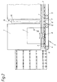
- An infeed and an outfeed conveyor can be arranged in front of (see FIG. 2) and after the device.
- the conveyor device 3 comprises two endlessly rotating conveyor belts 4 and 5, which run around drive or deflection rollers 6 and on which the glass panes 2 to be processed stand up.
- This driving device 8 comprises a carriage 9, which is guided on guide rails 10 parallel to the longitudinal extension of the conveyor belts 4 and 5.
- the carriage 9 carries at least one suction head 11 which faces the surface of a glass pane 2 resting on the supporting wall 1.
- a toothed belt 12 is assigned to it, which can be driven at the same linear speed as the conveyor belts 4 and 5. This can be done, for example, in that the toothed belt 12 runs around drive wheels 12 'which are arranged coaxially with the drive wheels 6 of the conveyor belts 4 and 5. If the driving device 8 is now to be moved synchronously with the conveyor belts 4 and 5, then this is driven by the toothed belt 12.
- this design of the drive for the driving device 8 ensures that it can also stand still when the conveyor belts 4 and 5 are in operation and, when used, in any case synchronously, i.e. is moved at the same linear speed as the conveyor belts 4 and 5.
- a slot 14 is provided in the support wall 1, through which a support roller 15 engages with an essentially vertical axis 16 parallel to the plane of the support wall 1.
- a glass pane 2 is supported in the region of the slot 14 of the support wall by means of this support roller 15, in the place of which a plurality of support rollers can also be provided and which, if desired, can be driven with a peripheral speed corresponding to the conveying speed of the conveyor belts 4 and 5.
- a processing tool 17 is provided opposite the slot 14 in the support wall 1 or the support roller 15 arranged therein.
- the machining tool 17 can be moved up and down via a slide 18 on a guide rail 19 which extends parallel to the supporting wall 1.
- the guide rail 19 is rigidly connected to a frame 20 of the device, to which the support wall 1 and the conveyor 3 and the driving device 8 are also attached.
- the carriage 18 is connected to a chain 22 which runs over deflection rollers 21 and is driven by a motor (not shown in more detail).
- the disk 24 which can be driven, for example, by a motor 23 and serves as a machining tool, is connected to a Swivel shaft 25, which in turn is received in bearing plates 26 fastened to the carriage.
- a Swivel shaft 25 On the pivot shaft 25 engages via a lever 27 connected to it, a pressure medium cylinder 28, so that the disc 24 from the position shown in Fig. 1 with a substantially horizontal axis of rotation, which is intended for machining the vertical edge regions of the glass plate 1 by one An angle of 90 ° is pivoted into a position in which the axis of rotation of the pane 24 is oriented essentially vertically and which is used to machine the upper and lower horizontal edge regions of the glass pane 2.
- a light barrier 29 which can be designed, for example, as a reflection light barrier.
- This light barrier 29 detects the essentially vertically aligned edges of the glass pane 2.
- a further light barrier 30 is provided on the slide 28, with which the upper horizontal edge of the glass pane 2 can be detected.
- the path of movement of the carriage 18 downwards is so limited that in the lower end position the processing tool 17 or, in the exemplary embodiment shown, the processing disk 24 in the for the processing of the lower horizontal edge of the glass sheet 2, the height orientation of which is determined by the conveyor belts 4 and 5 is at the correct altitude.
- the carriage 18 with the processing tool 17 is in its lower end position and the entraining device 8 is arranged in an area adjacent to the slot 14 in the support wall 1, but lying in front of the slot in the direction of movement.
- a glass sheet 2 to be processed is conveyed into the device via the feed conveyor until its front vertical edge is detected by the light barrier 29, whereupon the conveyor belts 4 and 5 are stopped.
- the glass pane then occupies a position in which its front vertical edge is exactly opposite in the processing tool, which is pivoted into its position with the horizontal axis of rotation of the pane 24, and is supported from behind by the roller 15.
- the suction head 11 of the driving device 8 is activated and the driving device 8 is coupled to the drive for the conveyor belts 4 and 5 in the manner described above.
- the slide 18 and thus the machining tool 17 are now moved upward, for example by a sequence control, until the pane 24 is located in the front upper corner of the glass pane 2.
- the stop of the carriage 18 at this altitude is effected by the light barrier 30.
- the processing tool 17 pivots by actuating the pressure cylinder 28 by 90 °, so that the axis of the disc 24 is now oriented substantially vertically.
- the drive for the conveyor belts 4 and 5 and thus also the driving device 8 is set in motion and the pane in FIG. 2 is moved further to the right, during which movement the upper horizontal edge region of the glass pane 2 is processed.
- the glass pane 2 is stopped by stopping the drives for the conveyor belts 4 and 5 and the driving device 8, and the pane 24 is pivoted back into its starting position by actuating the pressure medium cylinder 28 and the carriage 18 moves downward, the rear edge region of the glass pane 2 being processed at the same time.
- the disc 24 is pivoted again and then the drives for the conveyor belts 4 and 5 and the driving device 8 are set in motion such that the disc is moved to the left in FIG. 2 during which movement the lower horizontal edge area of the glass pane 2 is processed.
- the vacuum suction device 11 is released from the disk 2 and the coupling 31 of the drive for the driving device 8 is released from the drive for the conveyor belts 4 and 5.
- the conveyor belts 4 and 5 can then be set in motion for the removal of the glass pane 2.
- the support wall 1 can also be designed as a known support roller wall instead of an air cushion wall.
- the freely rotatable rollers 7 provided in the region of the support roller 15 are wider than the other freely rotatable rollers 7.
- these rollers 7 are arranged opposite guide rollers 38 which are arranged on the to be machined surface of the glass sheet 2 can be created.
- these guide rollers 38 are mounted on a frame 39 which is mounted in the frame 20 of the device so as to be pivotable about an axis 40 by a pressure medium cylinder 41.
- two guide rollers 38 will be provided on the frame, which are arranged on both sides of the machining tool 17 when it is in its lower starting position.
- the frame 39 has two arms which are arranged on both sides of the path of movement of the machining tool 17 and which, with their upper ends, carry the conveyor belts 4 and 5 across the guide rollers 38.
- the driving device 8 provided according to the invention can also be connected to the plate-shaped element 2 before it has reached the end position detected by the light barrier 29 for processing the vertical edge region which is at the front in the direction of movement.
- a further light barrier 42 can be provided in the region of the support wall 1.
Landscapes
- Engineering & Computer Science (AREA)
- Mechanical Engineering (AREA)
- Chemical & Material Sciences (AREA)
- Ceramic Engineering (AREA)
- Inorganic Chemistry (AREA)
- Grinding And Polishing Of Tertiary Curved Surfaces And Surfaces With Complex Shapes (AREA)
- Re-Forming, After-Treatment, Cutting And Transporting Of Glass Products (AREA)
- Container, Conveyance, Adherence, Positioning, Of Wafer (AREA)
Claims (8)
- Dispositif pour l'usinage des zones marginales de plaques de verte (2), comprenant une paroi support latérale (1), de préférence réalisée sous la forme d'une paroi à coussin d'air, pour les plaques de verre (2) disposées sensiblement verticalement, un dispositif de transport (3) placé sur le bord inférieur de la paroi support (1) et de préférence réalisé sous la forme d'au moins une bande transporteuse rotative sans fin, un outil d'usinage (17) guidé avec possibilité de déplacement vers le haut et vers le bas au moyen d'un chariot (18) sur un rail de guidage (19) sensiblement vertical, lequel outil est fixé au chariot (18) avec possibilité de pivotement de 90° autour d'un axe (33) perpendiculaire à la plaque de verte (2), l'outil d'usinage (17) comportant un disque de meulage ou de polissage (24) accouplé à un système d'actionnement rotatif pour l'enlèvement d'une couche, en particulier d'une couche métallique, des plaques de verte (2), le point d'attaque (34) du disque de meulage ou de polissage (24) sur une plaque de verte étant situé sur l'axe de pivotement (33) de l'outil d'usinage (17), une fente (14) sensiblement verticale pratiquée dans la paroi support (1) en face de l'outil d'usinage (17), dans laquelle est installé un rouleau d'appui (15) tournant autour d'un axe sensiblement vertical (16) et traversant au moins en partie la fente (14) de la paroi support (1), caractérisé par le fait que le rail de guidage (19) est lié au bâti (20) de dispositif, par le fait qu'un dispositif d'entraînement (8) des plaques de verte (2) est prévu entre l'extrémité inférieure de la paroi support (1) et le dispositif de transport (3), à l'opposé de l'outil d'usinage (17) rapporté aux plaques de verte (2), dispositif qui peut être déplacé au moins par instants en synchronisme avec le dispositif de transport (3), par le fait que sur le côté du dispositif de transport (3) qui est situé du côté de la paroi support (1) sont prévus des galets de soutien (7) librement mobiles en rotation dont les zones venant s'appliquer sur la plaque de verte (2) se situent sensiblement dans le plan de la paroi support (1), par le fait qu'il est prévu de chaque côté du rouleau d'appui (15), en vis-à-vis des galets de soutien (7), des galets de guidage (38) librement mobiles en rotation et venant s'appliquer sur le bord inférieur de la surface à usiner de la plaque de verte (2) et par le fait que les galets de guidage (38) sont disposés sur un cadre (39) mobile transversalement en plan de transport des plaques de verre (2).
- Dispositif selon la revendication 1, caractérisé par le fait que le dispositif d'entraînement (8) comporte au moins une ventouse (11) qui est montée sur un chariot (9) guidé parallèlement au dispositif de transport (3).
- Dispositif selon la revendication 2, caractérisé par le fait que pour l'actionnement du dispositif d'entraînement (8), il est prévu une bande sans fin (12), par exemple une courroie crantée, qui est disposée parallèlement au dispositif de transport (3) et qui peut être accouplée au système d'actionnement du dispositif de transport (3) et/ou sur laquelle on peut fixer (13) le chariot (9) du dispositif d'entraînement (8).
- Dispositif selon la revendication 3, caractérisé par le fait que la bande sans fin (12) pour le dispositif d'entraînement (8) et la bande transporteuse (4, 5) pour le dispositif de transport (3) passent autour de roues d'entraînement (6, 12') ou de poulies de renvoi coaxiales, la roue d'entraînement (12') pour la bande (12) pouvant être reliée par un accouplement débrayable (32) à l'arbre de commande (31) de la roue d'entraînement (6) du dispositif de transport (3).
- Dispositif selon l'une des revendications 1 à 4, caractérisé par le fait qu'à l'extrémité inférieure du rouleau d'appui (15) dans le plan d'action de l'outil d'usinage (17), dans lequel se situe également l'axe (16) du rouleau d'appui 15), est prévu au moins un dispositif, par exemple un barrage photo-électrique (29) ou analogue, détectant la présence d'une plaque de verte (2).
- Dispositif selon l'une des revendications 1 à 5, caractérisé par le fait que sur le chariot (18) de l'outil d'usinage (17) est prévu un dispositif (30) détectant le bord horizontal supérieur de la plaque de verte (2) s'appuyant sur la paroi support (1).
- Dispositif selon la revendication 1, caractérisé par le fait que le cadre (39) peut pivoter autour d'un axe (40) situé en-dessous du dispositif de transport (3) et parallèle à la direction du transport.
- Dispositif selon l'une des revendications 1 à 7, caractérisé par le fait que dans la zone de la hauteur du dispositif de transport (3) est prévu un autre outil d'usinage pour l'usinage du bord horizontal inférieur de la plaque de verte (2).
Applications Claiming Priority (2)
| Application Number | Priority Date | Filing Date | Title |
|---|---|---|---|
| AT1945/84 | 1984-06-14 | ||
| AT0194584A AT405724B (de) | 1984-06-14 | 1984-06-14 | Vorrichtung zum abtragenden bearbeiten der randbereiche einer glastafel |
Publications (4)
| Publication Number | Publication Date |
|---|---|
| EP0165232A2 EP0165232A2 (fr) | 1985-12-18 |
| EP0165232A3 EP0165232A3 (en) | 1987-09-30 |
| EP0165232B1 EP0165232B1 (fr) | 1990-09-05 |
| EP0165232B2 true EP0165232B2 (fr) | 1996-12-27 |
Family
ID=3524429
Family Applications (1)
| Application Number | Title | Priority Date | Filing Date |
|---|---|---|---|
| EP85890129A Expired - Lifetime EP0165232B2 (fr) | 1984-06-14 | 1985-06-13 | Dispositif pour l'usinage des bords d'éléments plans |
Country Status (4)
| Country | Link |
|---|---|
| US (1) | US4716686A (fr) |
| EP (1) | EP0165232B2 (fr) |
| AT (1) | AT405724B (fr) |
| DE (2) | DE8426496U1 (fr) |
Cited By (1)
| Publication number | Priority date | Publication date | Assignee | Title |
|---|---|---|---|---|
| EP3525984B1 (fr) | 2016-10-14 | 2020-11-04 | Forel Spa | Machine automatique et procédé automatique de meulage des bords de feuilles de verre |
Families Citing this family (38)
| Publication number | Priority date | Publication date | Assignee | Title |
|---|---|---|---|---|
| AT405724B (de) * | 1984-06-14 | 1999-11-25 | Lisec Peter | Vorrichtung zum abtragenden bearbeiten der randbereiche einer glastafel |
| KR910001987Y1 (ko) * | 1988-08-12 | 1991-03-30 | 박경 | 판유리 변형 면취기 |
| US5547063A (en) * | 1994-05-24 | 1996-08-20 | United Parcel Service Of America Inc. | Apparatus and method of sorting objects |
| IT1273917B (it) | 1994-10-28 | 1997-07-11 | For El Base Di Vianello Fortun | Procedimento e dispositivo per la rimozione dei rivestimenti depositatii sulla superficie di un vetro. |
| AT402395B (de) * | 1995-10-13 | 1997-04-25 | Lisec Peter | Vorrichtung zum umsetzen von isolierglasscheiben |
| PT769348E (pt) * | 1995-10-20 | 2001-08-30 | Vianello Fortunato D N Dba For | Metodo e dispositivo para remocao de coberturas aplicadas sobre a superficie de uma placa de vidro |
| DE19632240C2 (de) * | 1996-05-09 | 2001-10-04 | Hegla Fahrzeug Und Maschb Gmbh | Vorrichtung und Verfahren zum Entschichten von Flachglasrohplatten |
| IT1288656B1 (it) * | 1996-09-13 | 1998-09-23 | For El Base Di Vianello Fortun | Procedimento per il taglio di lastre di vetro e di lastre di vetro stratificato non blindato |
| IT1287347B1 (it) * | 1996-10-16 | 1998-08-04 | Castelmec Sas Di Rosso Valerio | Dispositivo per la sbordatura di lastre di vetro |
| IT1288675B1 (it) * | 1996-10-17 | 1998-09-23 | For El Base Di Vianello Fortun | Procedimento e macchina automatici per il taglio delle lastre di vetro stratificato e blindato |
| AT408856B (de) * | 1997-12-02 | 2002-03-25 | Lisec Peter | Vorrichtung zum automatischen säumen von plattenförmigen gegenständen |
| JP3915374B2 (ja) * | 2000-06-27 | 2007-05-16 | 坂東機工株式会社 | ガラス板の皮膜層除去方法及びその装置並びにその装置を具備したガラス板の加工装置 |
| JP2004518603A (ja) | 2001-02-08 | 2004-06-24 | カーディナル・シージー・カンパニー | 被覆基材の縁部処理方法 |
| DE10158646A1 (de) * | 2001-11-22 | 2003-06-12 | Lenhardt Maschinenbau | Vorrichtung zum Besäumen von Glastafeln |
| JP4254098B2 (ja) * | 2001-12-06 | 2009-04-15 | 坂東機工株式会社 | ガラス板の加工装置 |
| CA2464699C (fr) * | 2002-12-05 | 2010-04-20 | Peter Lisec | Dispositif d'usinage de plaques de materiau, comme des carreaux |
| US7125319B2 (en) | 2003-10-27 | 2006-10-24 | Corning Incorporated | Apparatus and method for grinding and/or polishing an edge of a glass sheet |
| US20050093207A1 (en) * | 2003-10-30 | 2005-05-05 | Simone John D. | Injection molding lid transfer apparatus and method |
| US7294045B1 (en) * | 2005-12-21 | 2007-11-13 | Corning Incorporated | Apparatus and method for edge processing of a glass sheet |
| AT504619B1 (de) * | 2006-12-04 | 2008-09-15 | Eckelt Glas Gmbh | Verfahren und vorrichtung zum bearbeiten von brandschutzglas |
| CN101626969A (zh) * | 2007-03-07 | 2010-01-13 | 株式会社爱发科 | 真空装置、基板搬送方法 |
| US9309714B2 (en) | 2007-11-13 | 2016-04-12 | Guardian Ig, Llc | Rotating spacer applicator for window assembly |
| PL2220320T3 (pl) | 2007-11-13 | 2020-01-31 | Guardian Glass, LLC | Pakiet szyb zespolonych i element dystansowy |
| US8449348B2 (en) * | 2009-01-13 | 2013-05-28 | Centre Luxembourg De Recherches Pour Le Verre Et La Ceramique S.A. (C.R.V.C.) | Techniques for debris reduction when performing edge deletion on coated articles having temporary protective coatings applied thereto |
| EP2580418B1 (fr) | 2010-06-10 | 2014-08-13 | Guardian IG, LLC | Applicateur d'entretoise de fenêtre |
| JP5677773B2 (ja) * | 2010-07-09 | 2015-02-25 | 川崎重工業株式会社 | 板状部材移載設備 |
| IT1401927B1 (it) * | 2010-09-14 | 2013-08-28 | Neptun S R L | Macchina molatrice a controllo numerico, particolarmente per lastre di vetro a lati rettilinei. |
| US9656356B2 (en) * | 2013-01-22 | 2017-05-23 | Guardian Ig, Llc | Window unit assembly station and method |
| ITTV20130168A1 (it) | 2013-10-17 | 2015-04-18 | Forel Spa | Macchina automatica e procedimento automatico per la rimozione localizzata dei rivestimenti depositati sulle lastre di vetro. |
| RU2612103C1 (ru) | 2013-10-18 | 2017-03-02 | Лисец Аустриа Гмбх | Способ для обработки поверхности предметов |
| AT516183B1 (de) * | 2014-10-06 | 2016-03-15 | Berndorf Band Gmbh | Verfahren zum Schleifen einer Schweißnaht eines Metallbands |
| US11148228B2 (en) | 2017-07-10 | 2021-10-19 | Guardian Glass, LLC | Method of making insulated glass window units |
| US10987902B2 (en) | 2017-07-10 | 2021-04-27 | Guardian Glass, LLC | Techniques for laser ablation/scribing of coatings in pre- and post-laminated assemblies, and/or associated methods |
| US10472274B2 (en) | 2017-07-17 | 2019-11-12 | Guardian Europe S.A.R.L. | Coated article having ceramic paint modified surface(s), and/or associated methods |
| UA124077C2 (uk) * | 2017-11-30 | 2021-07-14 | Лісец Аустріа Гмбх | Пристрій для різання по суті вертикально орієнтованих пластинчатих матеріалів |
| IT202200006089A1 (it) * | 2022-03-29 | 2023-09-29 | Forel S P A Unipersonale | Apparato e procedimento per la lavorazione di lastre |
| IT202200017652A1 (it) * | 2022-08-25 | 2024-02-25 | Forel S P A Unipersonale | Unità e relativo procedimento per trattenere una lastra |
| DE102022123443A1 (de) | 2022-09-14 | 2023-08-31 | Glaston Germany GmbH | Verfahren und Vorrichtung zum Herstellen von Isolierglasscheiben |
Family Cites Families (35)
| Publication number | Priority date | Publication date | Assignee | Title |
|---|---|---|---|---|
| DE8335764U1 (de) * | 1984-07-05 | Lisec, Peter, Amstetten-Hausmening, Niederösterreich | Vorrichtung zum Bearbeiten der Randbereiche tafelförmiger Elemente | |
| FR360126A (fr) * | 1905-06-16 | 1906-04-13 | Joel Frankinet Kirby | Machine à biseauter automatiquement les glaces de toutes dimensions |
| US1831617A (en) * | 1928-07-26 | 1931-11-10 | Libbey Owens Ford Glass Co | Table for supporting glass sheets and method of bedding the same thereon |
| US1966869A (en) * | 1933-11-23 | 1934-07-17 | Pittsburgh Plate Glass Co | Apparatus for grinding the edges of glass sheets |
| US2075369A (en) * | 1935-09-30 | 1937-03-30 | Stetler Lowell | Marble refacing machine |
| US2671241A (en) * | 1947-08-23 | 1954-03-09 | Libbey Owens Ford Glass Co | Glass drying apparatus |
| US2551332A (en) * | 1947-11-06 | 1951-05-01 | Binswanger Mirror Co | Machine for processing sheetlike objects |
| GB743180A (en) * | 1951-06-12 | 1956-01-11 | Charles Edouard Chaudron | Improvements in or relating to the grinding and polishing of glass |
| IT501791A (fr) * | 1953-05-26 | |||
| US2795086A (en) * | 1952-11-21 | 1957-06-11 | Libbey Owens Ford Glass Co | Edge finishing method and apparatus |
| GB851141A (en) * | 1957-12-16 | 1960-10-12 | Pilkington Brothers Ltd | Improvements relating to the production of bevels on glass plates |
| US3023548A (en) * | 1960-10-06 | 1962-03-06 | Sun Tool And Machine Company | Automatic contour edge grinder |
| US3565139A (en) * | 1968-08-06 | 1971-02-23 | Eugene T Olson | Angularly shiftable saw mount |
| GB1370945A (en) * | 1971-04-16 | 1974-10-16 | Triplex Safety Glass Co | Conveying apparatus |
| FR2195566A1 (en) * | 1972-08-07 | 1974-03-08 | Saint Gobain | Glass sheet edge machining holder - is rotatable and lockable in various settings |
| IT984759B (it) * | 1973-04-12 | 1974-11-20 | Zafferani A Nc Soc | Macchina automatica per la fabbri cazione di pannelli isolanti a dop pio vetro |
| US3835591A (en) * | 1973-05-14 | 1974-09-17 | Goodrich Co B F | Method and apparatus for correcting dimensional variation in a rotating tire |
| FR2237244A1 (fr) * | 1973-07-12 | 1975-02-07 | Intercontinental Trading Cy | |
| US3918209A (en) * | 1974-08-19 | 1975-11-11 | British Oxygen Co Ltd | Metal removal apparatus |
| US3943667A (en) * | 1975-07-11 | 1976-03-16 | Acme Steel Door Corporation | Automatic weld grinding machine |
| BE838121R (fr) * | 1976-01-30 | 1976-05-14 | Machine a chanfreiner les bords de plaques de verre | |
| US4060938A (en) * | 1976-04-20 | 1977-12-06 | Barron Sr Lee H | Glass beveling machine |
| US4354796A (en) * | 1976-05-10 | 1982-10-19 | Bergman Raymond A | Air float power translation system |
| JPS5493288A (en) * | 1977-12-31 | 1979-07-24 | Bando Kiko Co | Glass chamfering machine |
| US4228617A (en) * | 1977-12-31 | 1980-10-21 | Bando Kiko Co., Ltd | Method for grinding glass plates and the like through numerical control and beveling machine therefor |
| DE2846785C2 (de) * | 1978-10-27 | 1984-07-19 | Karl 7531 Neuhausen Lenhardt | Vorrichtung zum automatischen Füllen der Randfugen von Zwei- oder Mehrfach- Isolierglasscheiben mit einem Dichtungsmittel unter Verwendung von Fülldüsen |
| DE2816437B1 (de) * | 1978-04-15 | 1979-08-16 | Karl Lenhardt | Vorrichtung zum automatischen Fuellen der Randfugen von Isolierglasscheiben mit einem Dichtungsmittel durch Fuellduesen |
| GB1574751A (en) * | 1978-05-10 | 1980-09-10 | Wood Jenks & Co Ltd | Rectangular plate handling apparatus |
| DE2939571C2 (de) * | 1979-09-29 | 1982-08-12 | Paul Dipl.-Ing. 6925 Eschelbronn Ernst Jun. | Laufendes Transportband für Schleifmaschinen |
| DE3205351A1 (de) * | 1982-02-15 | 1983-08-25 | Glas - und Spiegel-Manufactur AG, 4650 Gelsenkirchen | Verfahren zur herstellung von mit einer metallischen reflektierenden oberflaechenschicht versehenen isolierglasscheiben |
| EP0095228B1 (fr) * | 1982-03-30 | 1986-06-11 | Pilkington Brothers P.L.C. | Traitement du verre recouvert |
| DE8318401U1 (de) * | 1983-06-24 | 1983-09-15 | Lisec, Peter, Amstetten-Hausmening, Niederösterreich | Vorrichtung zum Fördern von tafelförmigen Elementen |
| DE3448277C2 (fr) * | 1984-03-09 | 1992-03-05 | Peter Amstetten-Hausmening At Lisec | |
| AT405724B (de) * | 1984-06-14 | 1999-11-25 | Lisec Peter | Vorrichtung zum abtragenden bearbeiten der randbereiche einer glastafel |
| JPH10446A (ja) * | 1996-06-18 | 1998-01-06 | Kanegafuchi Chem Ind Co Ltd | 廃棄物処理剤および処理方法 |
-
1984
- 1984-06-14 AT AT0194584A patent/AT405724B/de not_active IP Right Cessation
- 1984-09-07 DE DE19848426496U patent/DE8426496U1/de not_active Expired
-
1985
- 1985-06-13 EP EP85890129A patent/EP0165232B2/fr not_active Expired - Lifetime
- 1985-06-13 DE DE8585890129T patent/DE3579505D1/de not_active Expired - Lifetime
- 1985-06-14 US US06/744,753 patent/US4716686A/en not_active Expired - Fee Related
Cited By (1)
| Publication number | Priority date | Publication date | Assignee | Title |
|---|---|---|---|---|
| EP3525984B1 (fr) | 2016-10-14 | 2020-11-04 | Forel Spa | Machine automatique et procédé automatique de meulage des bords de feuilles de verre |
Also Published As
| Publication number | Publication date |
|---|---|
| EP0165232B1 (fr) | 1990-09-05 |
| US4716686A (en) | 1988-01-05 |
| AT405724B (de) | 1999-11-25 |
| EP0165232A2 (fr) | 1985-12-18 |
| ATA194584A (de) | 1989-04-15 |
| DE8426496U1 (de) | 1984-11-29 |
| DE3579505D1 (de) | 1990-10-11 |
| EP0165232A3 (en) | 1987-09-30 |
Similar Documents
| Publication | Publication Date | Title |
|---|---|---|
| EP0165232B2 (fr) | Dispositif pour l'usinage des bords d'éléments plans | |
| DE3637561C2 (fr) | ||
| DE50208224C5 (de) | Vorrichtung und verfahren zum bewegen von glastafeln beim bearbeiten derselben | |
| EP0549556B1 (fr) | Dispositif pour convoyer des plaques de verre isolantes | |
| AT515212A4 (de) | Verfahren zum Fördern von Isolierglas-Rohlingen | |
| EP1314513B1 (fr) | Procédé pour l'ébavurage de plaques de verre | |
| EP0311699A1 (fr) | Dispositif de transport pour retourner au même niveau des colis de détail | |
| DE4437998C2 (de) | Vorrichtung zum Zusammenbauen von Isolierglasscheiben | |
| DE2122990C3 (de) | Maschine zum Bearbeiten der Kanten von Glasscheiben o.dgl. | |
| DE2430043A1 (de) | Verfahren zum beschneiden von papierstapeln | |
| DE1008882B (de) | Automatische Glasschneidevorrichtung an einer kontinuierlich bewegbaren Foerdervorrichtung fuer Flachglas | |
| EP0857849B1 (fr) | Procédé et dispositif d'assemblage et pour vitrifier de vitrages isolants | |
| DE8135650U1 (de) | "pufferkettenfoerderer" | |
| EP0204063A1 (fr) | Dispositif pour le nettoyage de plaques de verre | |
| DE3400031C1 (de) | Vorrichtung zum Fördern von randverklebten Isolierglasscheiben | |
| EP0857848B1 (fr) | Procédé et dispositif d'assemblage de vitrages isolants | |
| DE3448277C2 (fr) | ||
| EP1262290A2 (fr) | Dispositif de sciage pour panneaux en bois, en matière plastique, ou similaire | |
| DE3345940A1 (de) | Vorrichtung zum handhaben von isolierglasscheiben | |
| AT403911B (de) | Verfahren und vorrichtung zum abtragen einer metallbeschichtung von glastafeln | |
| EP0457720B1 (fr) | Dispositif d'alimentation pour une machine pour l'assemblage de feuilles de placage en bande continue | |
| DE8335764U1 (de) | Vorrichtung zum Bearbeiten der Randbereiche tafelförmiger Elemente | |
| EP0689909B1 (fr) | Chaîne transporteuse plane pour trancher des feuilles de bois | |
| DE10147656C1 (de) | Vorrichtung zum Bewegen von Glastafeln beim Bearbeiten derselben | |
| DE2112908A1 (de) | Verfahren und Vorrichtung zum Zerteilen einer Glasplatte in rechteckige Stuecke vorgegebener Groesse |
Legal Events
| Date | Code | Title | Description |
|---|---|---|---|
| PUAI | Public reference made under article 153(3) epc to a published international application that has entered the european phase |
Free format text: ORIGINAL CODE: 0009012 |
|
| AK | Designated contracting states |
Designated state(s): DE FR GB IT |
|
| PUAL | Search report despatched |
Free format text: ORIGINAL CODE: 0009013 |
|
| AK | Designated contracting states |
Kind code of ref document: A3 Designated state(s): DE FR GB IT |
|
| 17P | Request for examination filed |
Effective date: 19880329 |
|
| 17Q | First examination report despatched |
Effective date: 19890720 |
|
| ITF | It: translation for a ep patent filed | ||
| GRAA | (expected) grant |
Free format text: ORIGINAL CODE: 0009210 |
|
| AK | Designated contracting states |
Kind code of ref document: B1 Designated state(s): DE FR GB IT |
|
| ET | Fr: translation filed | ||
| GBT | Gb: translation of ep patent filed (gb section 77(6)(a)/1977) | ||
| REF | Corresponds to: |
Ref document number: 3579505 Country of ref document: DE Date of ref document: 19901011 |
|
| PLBI | Opposition filed |
Free format text: ORIGINAL CODE: 0009260 |
|
| 26 | Opposition filed |
Opponent name: LENHARDT MASCHINENBAU GMBH Effective date: 19901013 |
|
| ITTA | It: last paid annual fee | ||
| APAC | Appeal dossier modified |
Free format text: ORIGINAL CODE: EPIDOS NOAPO |
|
| PLAW | Interlocutory decision in opposition |
Free format text: ORIGINAL CODE: EPIDOS IDOP |
|
| PUAH | Patent maintained in amended form |
Free format text: ORIGINAL CODE: 0009272 |
|
| STAA | Information on the status of an ep patent application or granted ep patent |
Free format text: STATUS: PATENT MAINTAINED AS AMENDED |
|
| 27A | Patent maintained in amended form |
Effective date: 19961227 |
|
| AK | Designated contracting states |
Kind code of ref document: B2 Designated state(s): DE FR GB IT |
|
| ITF | It: translation for a ep patent filed | ||
| GBTA | Gb: translation of amended ep patent filed (gb section 77(6)(b)/1977) |
Effective date: 19891224 |
|
| ET3 | Fr: translation filed ** decision concerning opposition | ||
| REG | Reference to a national code |
Ref country code: GB Ref legal event code: IF02 |
|
| PGFP | Annual fee paid to national office [announced via postgrant information from national office to epo] |
Ref country code: GB Payment date: 20040609 Year of fee payment: 20 |
|
| PGFP | Annual fee paid to national office [announced via postgrant information from national office to epo] |
Ref country code: FR Payment date: 20040610 Year of fee payment: 20 |
|
| PGFP | Annual fee paid to national office [announced via postgrant information from national office to epo] |
Ref country code: DE Payment date: 20040819 Year of fee payment: 20 |
|
| PG25 | Lapsed in a contracting state [announced via postgrant information from national office to epo] |
Ref country code: GB Free format text: LAPSE BECAUSE OF EXPIRATION OF PROTECTION Effective date: 20050612 |
|
| REG | Reference to a national code |
Ref country code: GB Ref legal event code: PE20 |
|
| APAH | Appeal reference modified |
Free format text: ORIGINAL CODE: EPIDOSCREFNO |